

Page 1
User’s manual
IN-VEHICLE COMPUTING
Page 2

VBOX-3150 Manual
1
SINTRONES® Technology Corp.
User Manual
Copyright
© 2009 by SINTRONES® Technology Corp. All Rights Reserved.
No part of this publication may be reproduced, transcribed, stored in a retrieval system,
translated into any language, or transmitted in any form or by any means such as
electronic, mechanical, magnetic, optical, chemical, photocopy, manual, or otherwise,
without prior written permission from SINTRONES® Technology Corp.
Other brands and product names used herein are for identification purposes only and
may be trademarks of their respective owners.
Disclaimer
SINTRONES® Technology Corp. shall not be liable for any incidental or consequential
damages resulting from the performance or use of this product.
SINTRONES® Technology Corp. makes no representation or warranty regarding the
content of this manual. Information in this manual had been carefully checked for
accuracy; however, no guarantee is given as to the correctness of the contents. For
continuing product improvement, SINTRONES® Technology Corp. reserves the right to
revise the manual or make changes to the specifications of this product at any time
without notice and obligation to any person or entity regarding such change. The
information contained in this manual is provided for general use by customers.
This device complies to Part 15 of the FCC Rules. Operation is subject to the following
two conditions:
1. This device may not cause harmful interference.
2. This device must withstand any background interference including those that may
cause undesired operation.
Page 3

VBOX-3150 Manual
2
Safety Information
Read the following precautions before setting up a SINTRONES Product.
Electrical safety
To prevent electrical shock hazard, disconnect the power cable from the electrical
outlet before relocating the system.
When adding or removing devices to or from the system, ensure that the power
cables for the devices are unplugged before the signal cables are connected. If
possible, disconnect all power cables from the existing system before you add a
device.
Before connecting or removing signal cables from the motherboard, ensure that
all power cables are unplugged.
Seek professional assistance before using an adapter or extension cord. These
devices could interrupt the grounding circuit.
Make sure that your power supply is set to the correct voltage in your area. If you
are not sure about the voltage of the electrical outlet you are using, contact your
local power company.
If the power supply is broken, do not try to fix it by yourself. Contact a qualified
service technician or your retailer.
Operation safety
Before installing the motherboard and adding devices on it, carefully read all the
manuals that came with the package.
Before using the product, make sure all cables are correctly connected and the
power cables are not damaged. If you detect any damage, contact your dealer
immediately.
To avoid short circuits, keep paper clips, screws, and staples away from
connectors, slots, sockets and circuitry.
Avoid dust, humidity, and temperature extremes. Do not place the product in any
area where it may become wet.
Place the product on a stable surface.
If you encounter technical problems with the product, contact a qualified service
technician or your retailer.
Page 4

VBOX-3150 Manual
3
CAUTION
Incorrectly replacing the battery may damage this computer. Replace only with the
same or its equivalent as recommended by SINTRONES® Technology Corp. Dispose
used battery according to the manufacturer's instructions.
Technical Support
Please do not hesitate to call or e-mail our customer service when you still cannot fix
the problems.
Tel : +886-2-82280101
Fax : +886-2-82280100
E-mail : [email protected]
Website : www.sintrones.com
Page 5

VBOX-3150 Manual
4
Content
1. Introduction ................................................................................................................................ 6
Specification.............................................................................................................................. 6
2. Illustration (MB/System) .............................................................................................................. 8
Front I/O ................................................................................................................................... 9
Rear I/O .................................................................................................................................... 9
System .................................................................................................................................... 10
3. Architecture .............................................................................................................................. 11
4. Principal component Specification ............................................................................................... 11
CPU ....................................................................................................................................... 11
5. Internal Connector ..................................................................................................................... 12
VGA Connector ....................................................................................................................... 12
LINE Connector....................................................................................................................... 12
LOUT2 connector .................................................................................................................... 13
GPIO Connector ...................................................................................................................... 13
COM Port Connector ................................................................................................................ 14
USB Connector ........................................................................................................................ 15
SATA Connector ..................................................................................................................... 16
UPS Connector ........................................................................................................................ 17
Mini PCI-E connector ............................................................................................................... 18
SATA Power Connector ........................................................................................................... 20
6. External connector specification .................................................................................................. 21
COM connector ....................................................................................................................... 21
DVI-I connector ....................................................................................................................... 22
7. System Installation .................................................................................................................... 23
System Introduction ................................................................................................................. 23
Opening Chassis ...................................................................................................................... 24
Page 6

VBOX-3150 Manual
5
Installing SSD card................................................................................................................... 26
Installing Memory .................................................................................................................... 28
Installing MINI PCIe Expansion Card (MINICARD1) .................................................................. 29
Installing MINI PCIe Expansion Card (MINICARD2, 3, 4) ........................................................... 30
Installing Internal Antenna Cable ............................................................................................... 31
Installing SIM Card .................................................................................................................. 32
8. SYSTEM RESOURCE .............................................................................................................. 33
Ignition Power Management Quick Guide ................................................................................... 33
Page 7
VBOX-3150 Manual
6
INTRODUCTION
Specification
System
CPU
Intel Gen4 Core i3-4010U 1.7GHz
Intel Gen4 Dual Core 2980U 1.6 GHz
(Optional i5, i7)
Memory
1 x DDR3L-1600 SO-DIMM up to 8GB
LAN Chipset
2 x Intel i210-AT Gigabit Ethernet with PoE 802.3af (15.4W per port)
1 x Intel i-218LM GbE support vPro (iAMT9.5 w/ i5, i7 only)
Audio
Mic-in/Line-out (option 2 x Line--out)
Watchdog
1 ~ 255 Level Reset
Power Requirement
Power Input
9V - 36V DC Power Input
Power Protection
Power Management
Vehicle Power Ignition for Variety Vehicle
Power Off Control
Power off Delay Time Setting by BIOS and Software
Battery (UPS)
Internal Battery Kit for 10 Mins Operating (Optional)
Patent No. : M447854 - Build-in Battery
Storage
Type
1 x 2.5” Drive Bay for SATA Type Hard Disk Drive / SSD
1 x SATA DOM
Graphics
Graphics
Intel HD Graphics
Resolution
Page 8
VBOX-3150 Manual
7
Qualification
Certifications
CE, FCC Class A, E-13
I/O
Serial Port
4 x RS-232 (2 with RS-232/422/485)
USB Port
2 x USB 3.0 and 1 x USB 2.0 Ports
LAN
3 x RJ45 Ports for GbE (2 x PoE 802.3af 15.4W per port, 1 x support
vPro)
Video Port
1 x HDMI, 1 x DVI-I and 1 x VGA
DIO Port
4 In and 4 Out
Audio
Mic-in/Line-out (option 2 x Line--out)
SIM Card Socket
2 x SIM Card Sockets Supported Onboard with eject
Environment
Operating Temp.
-40 ~ 70ºC (SSD), ambient w/ air
Storage Temp.
-40 ~ 80ºC
Relative Humidity
10 ~ 90% (non-condensing)
Vibration (random)
2.5g@5~500 Hz with SSD
Vibration Operating
MIL-STD-810F, Method 514.5, Category 20,
Ground Vehicle-Highway
Truck Storage
MIL-STD-810F, Method 514.5, Category 24, Integrity Test
Shock
Operating: MIL-STD-810F, Method 516.5, Procedure I,
Trucks and semi-trailers=15G (11ms) with SSD
Crash Hazard
MIL-STD-810F, Method 516.5, Procedure V,
Ground equipment=100g
Mechanical
Construction
Aluminum Alloy
Mounting
Wall-mount, VESA-mount, Din Rail Mounting Kit
Weight
1406 g
Dimensions
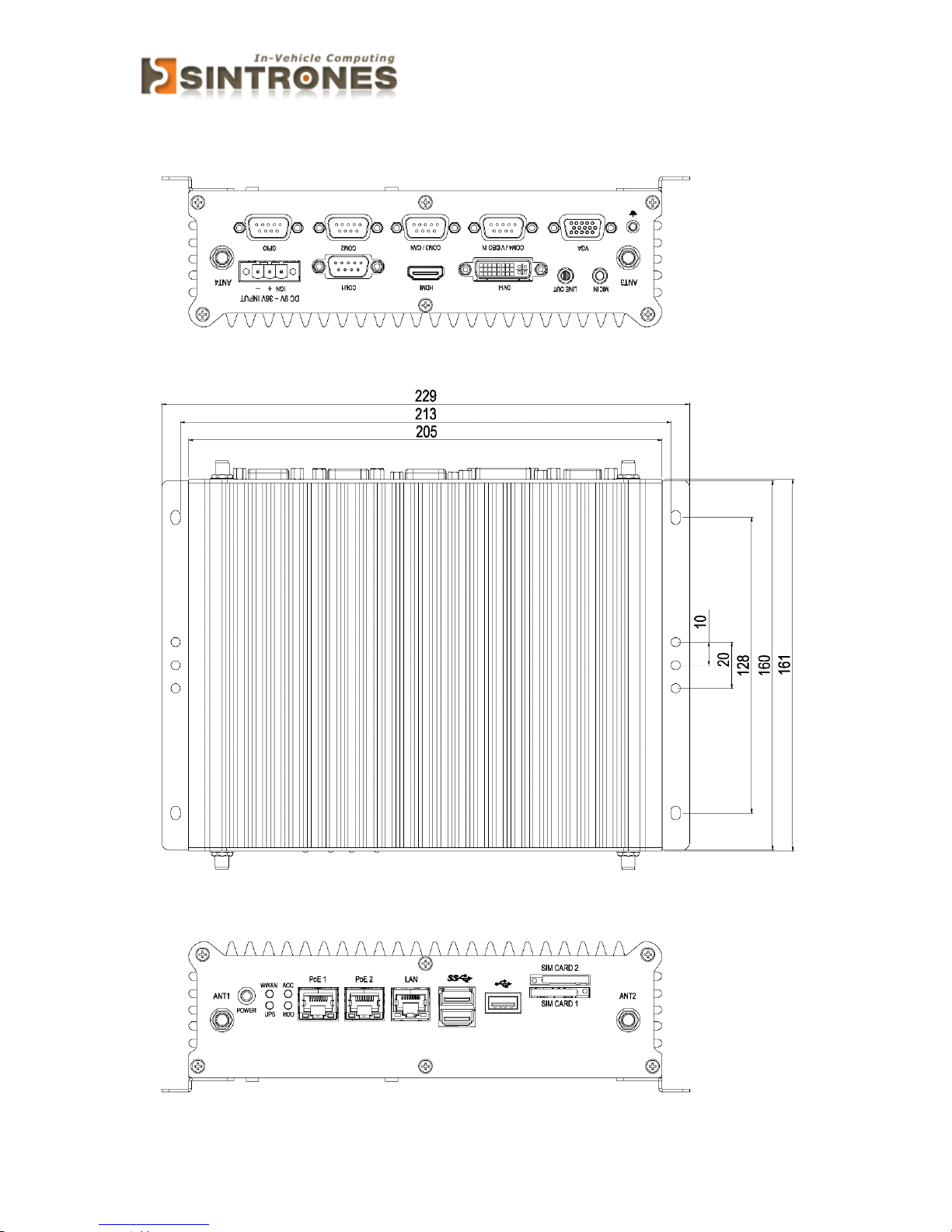
229 x 161 x 65 mm
Page 9
VBOX-3150 Manual
8
ILLUSTRATION (MB/SYSTEM)
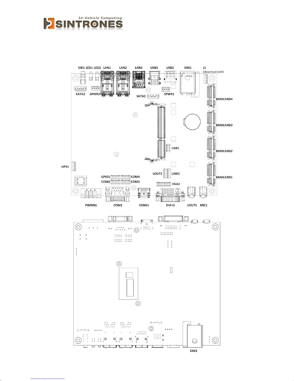
Main board
Page 10
VBOX-3150 Manual
9
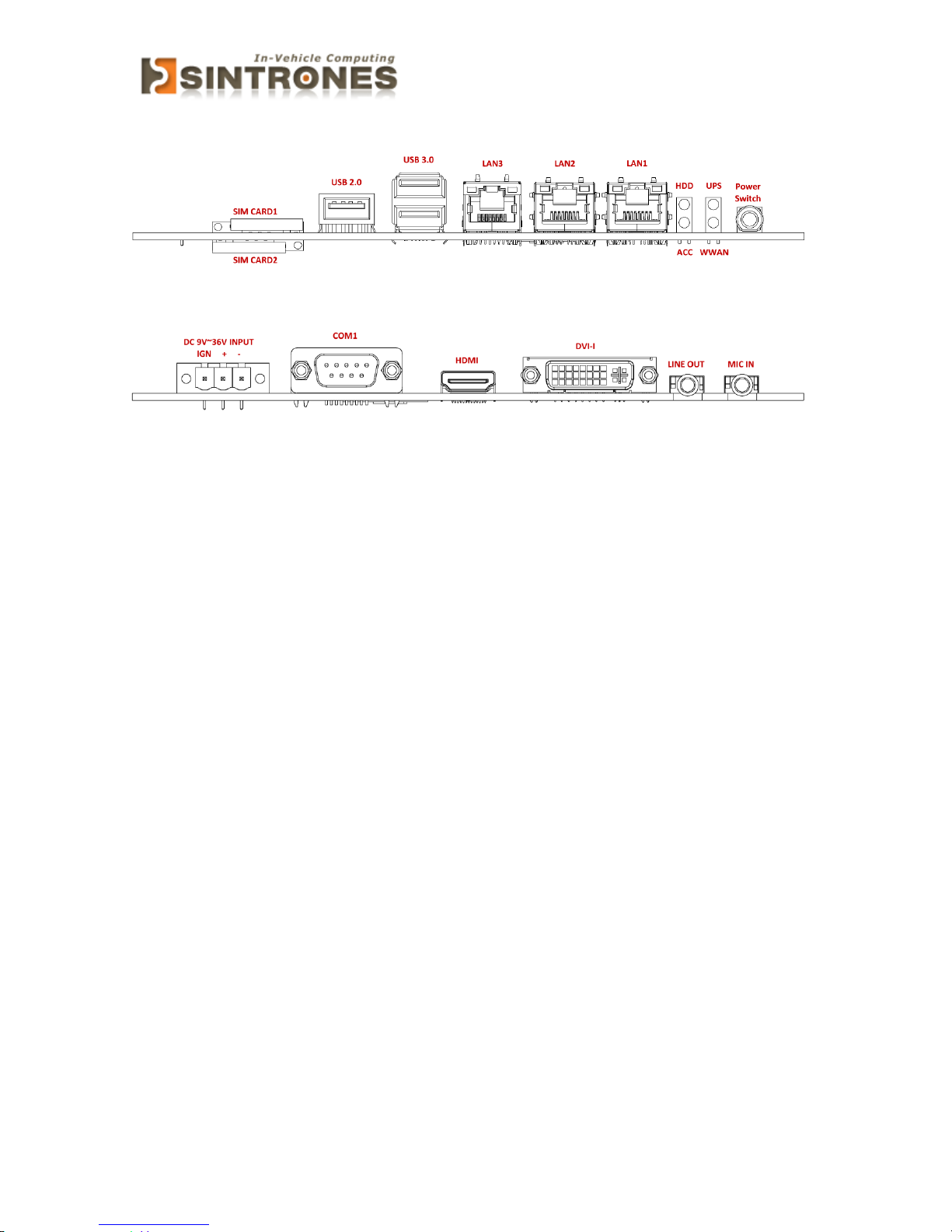
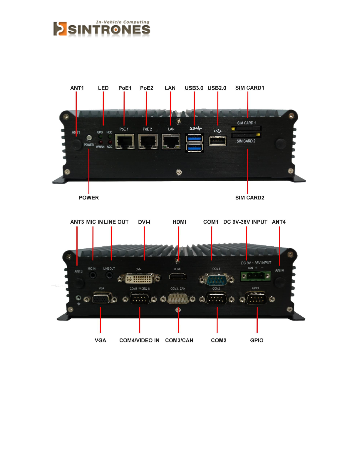
Front I/O
Rear I/O
Page 11
VBOX-3150 Manual
10
System
Page 12
VBOX-3150 Manual
11
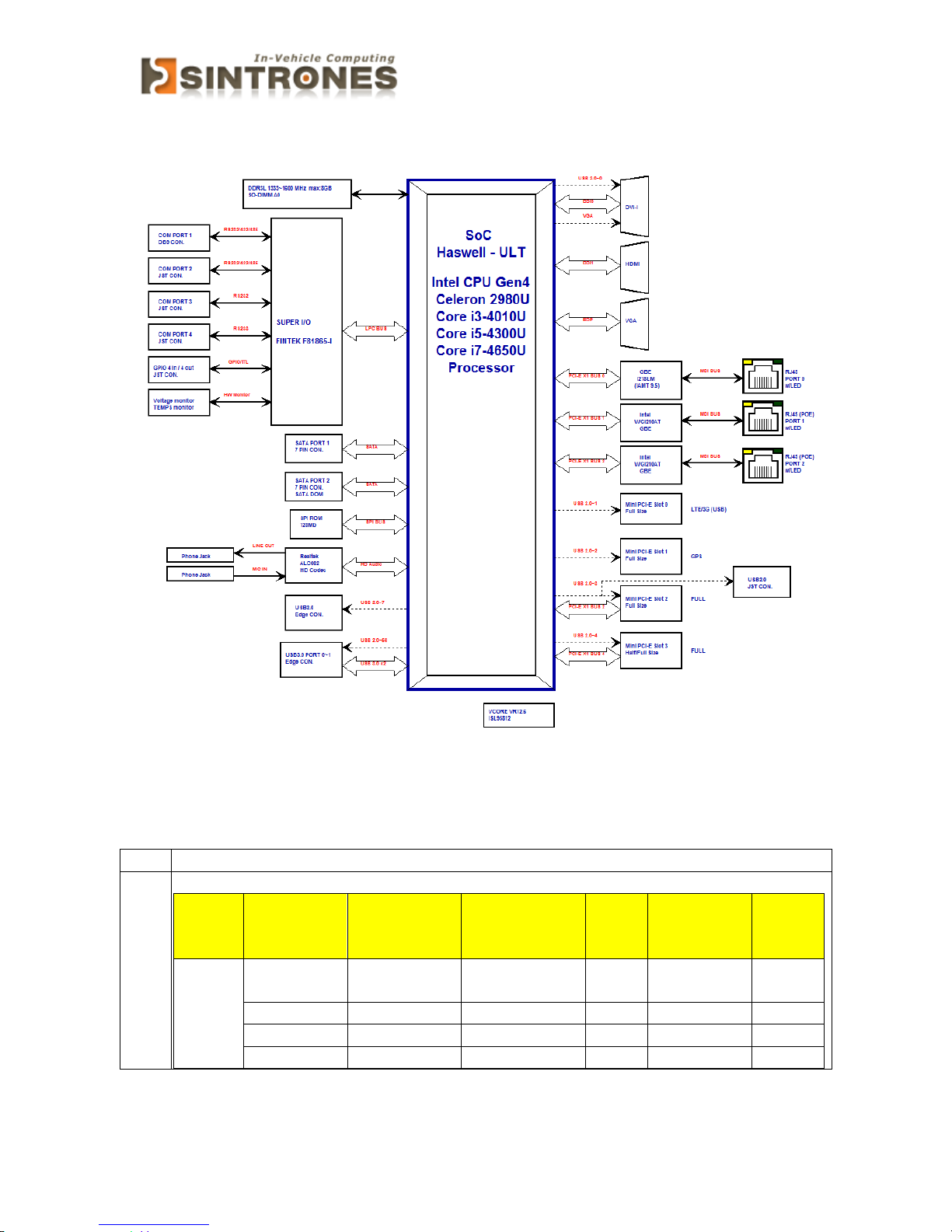
ARCHITECTURE
PRINCIPAL COMPONENT SPECIFICATION
CPU
Chip
Description
Intel
1. Power consumption:
Symbol
Processor
Number
Core
Frequency/
GHz
Thermal
Design Power
Unit
Tj max(
C
o
)
Cache
Celeron2980U
1.6GHz
15 W 100
2M
i3-4010U
1.7GHz
15 W 100
3M
i5-4300U
1.9GHz
15 W 100
3M
i7- 4650U
1.7GHz
15 W 100
4M
Page 13
VBOX-3150 Manual
12
INTERNAL CONNECTOR
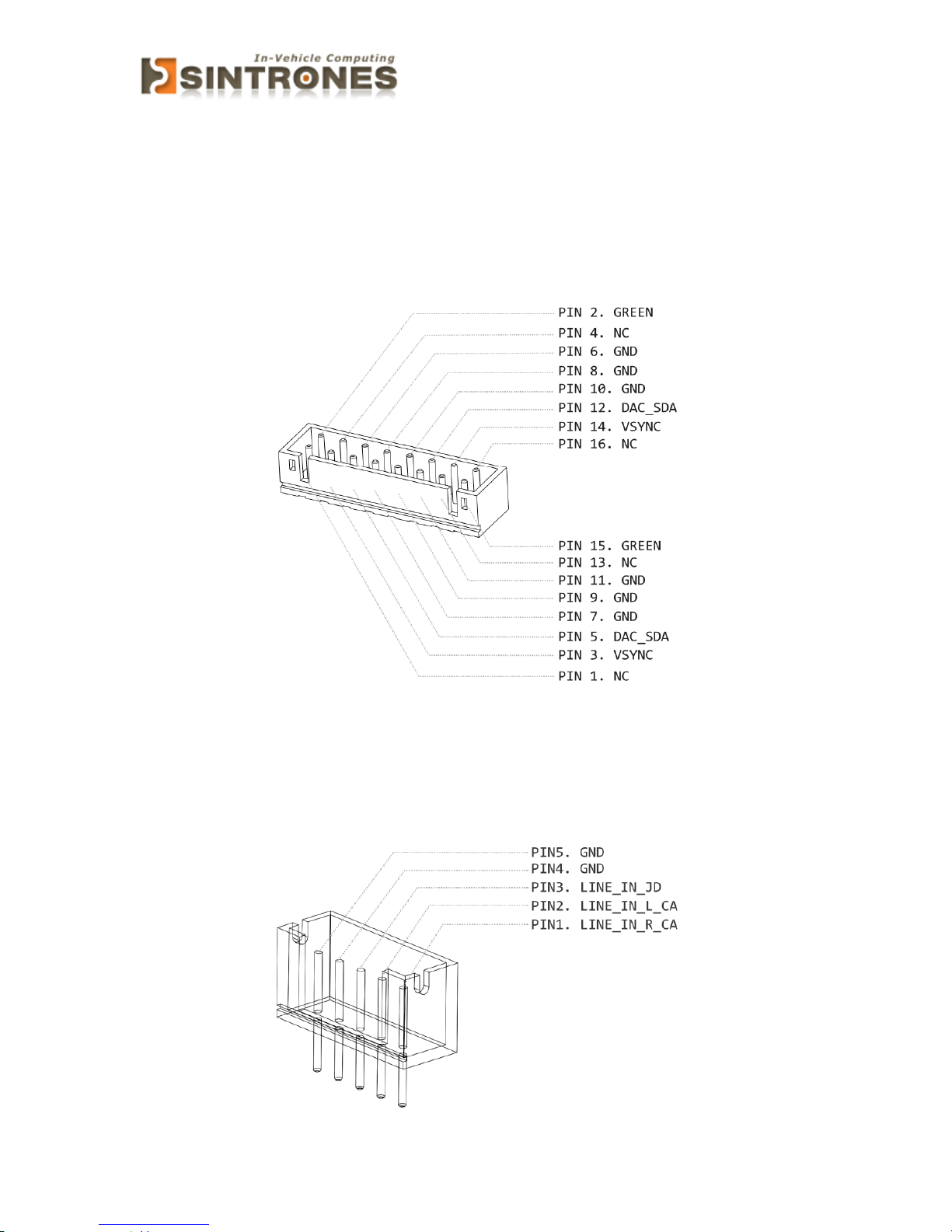
VGA Connector
Connector location: VGA1
Connector size: 2 X 8 = 16 Pin
Connector type: JST-2.0mm-M-180
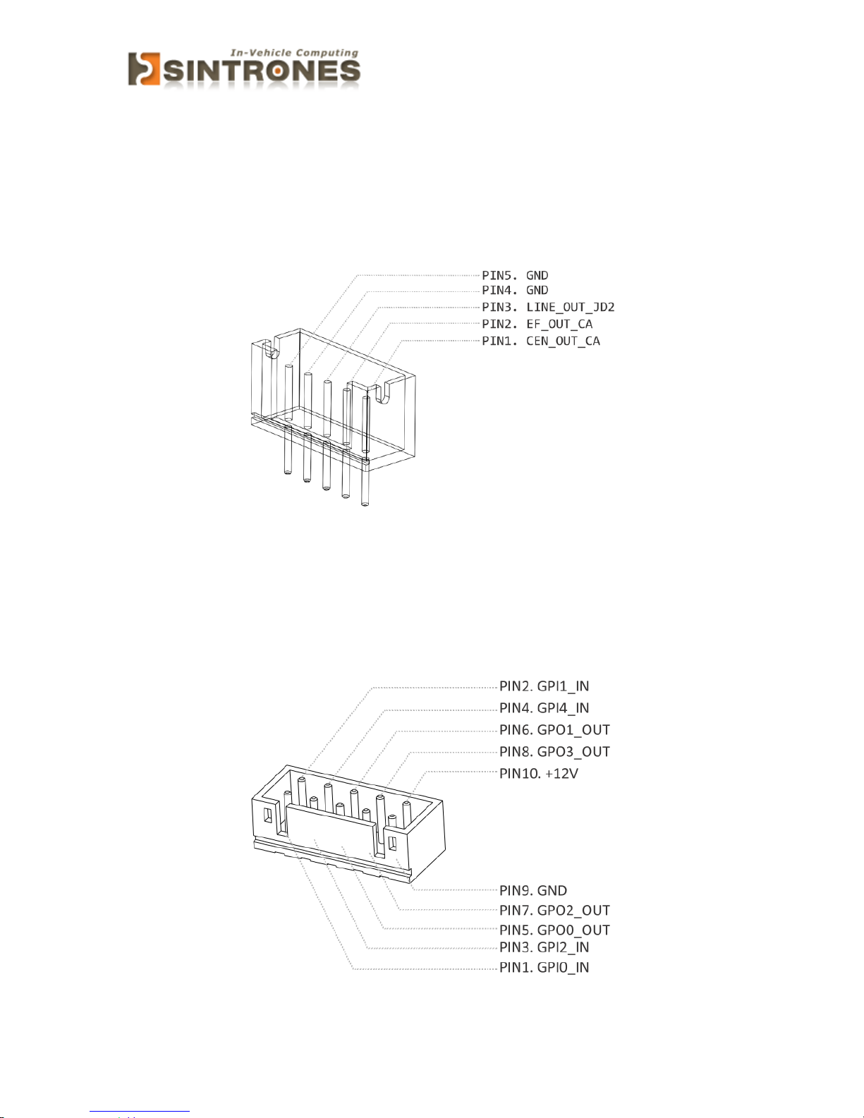
LINE Connector
Connector location: LINE1
Connector size: 1 X 5 = 5 Pin
Connector type: JST-2.0mm-M-180
Page 14
VBOX-3150 Manual
13
LOUT2 connector
Connector location: LOUT2
Connector size: 1 X 5 = 5 Pin
Connector type: JST-2.0mm-M-180
GPIO Connector
Connector location: GPIO1
Connector size: 2 X 5 = 10 Pin
Connector type: JST-2.0mm-M-180
Page 15
VBOX-3150 Manual
14
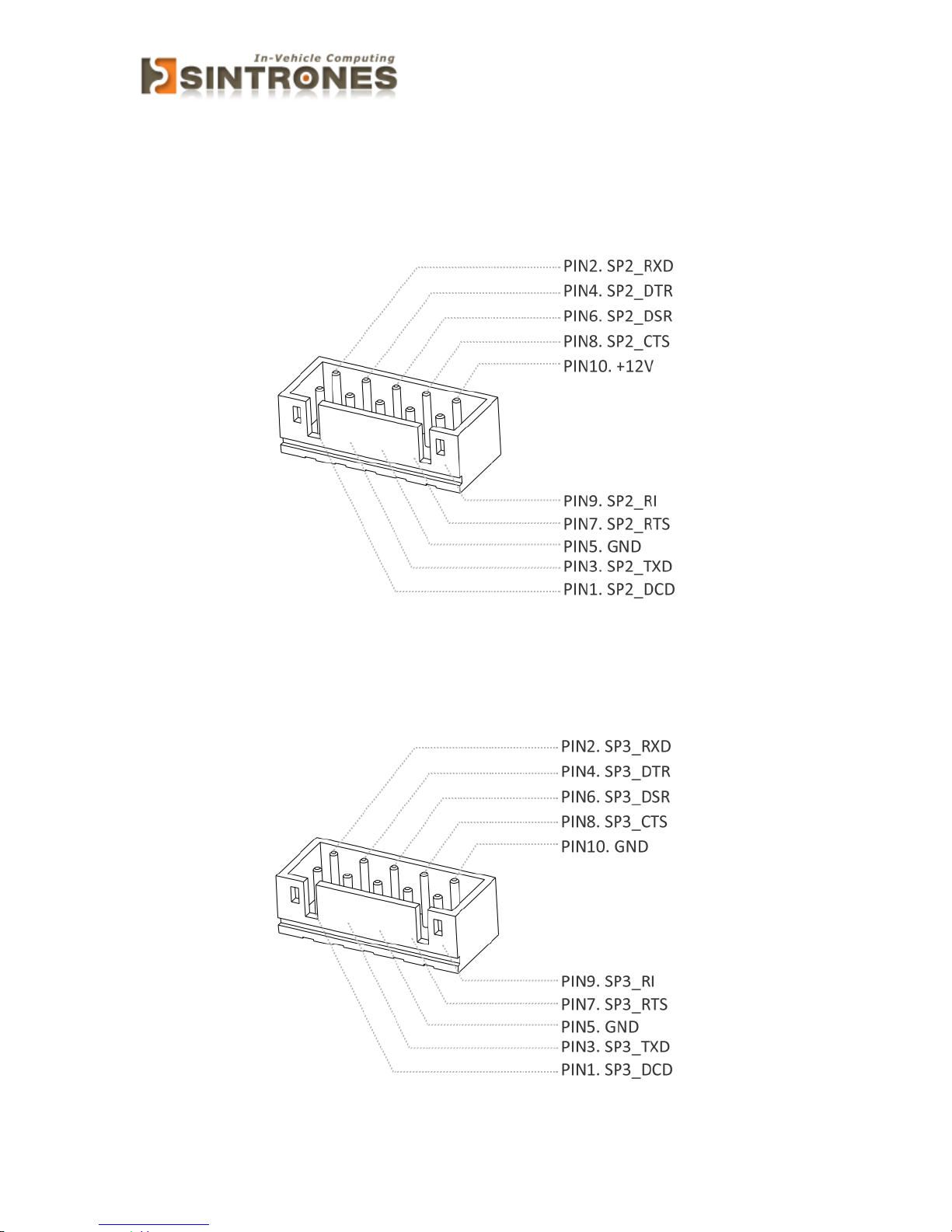
COM Port Connector
Connector location: COM2
Connector size: 2 X 5 = 10 Pin
Connector type: JST-2.0mm-M-180
Connector location: COM3
Connector size: 2 X 5 = 10 Pin
Connector type: JST-2.0mm-M-180
Page 16
VBOX-3150 Manual
15
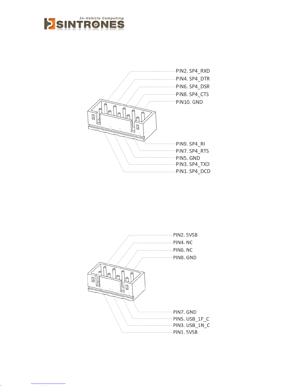
Connector location: COM4
Connector size: 2 X 5 = 10 Pin
Connector type: JST-2.0mm-M-180
USB Connector
Connector location: USB1
Connector size: 2 X 4= 8Pin
Connector type: JST-2.0mm-M-180
Page 17
VBOX-3150 Manual
16
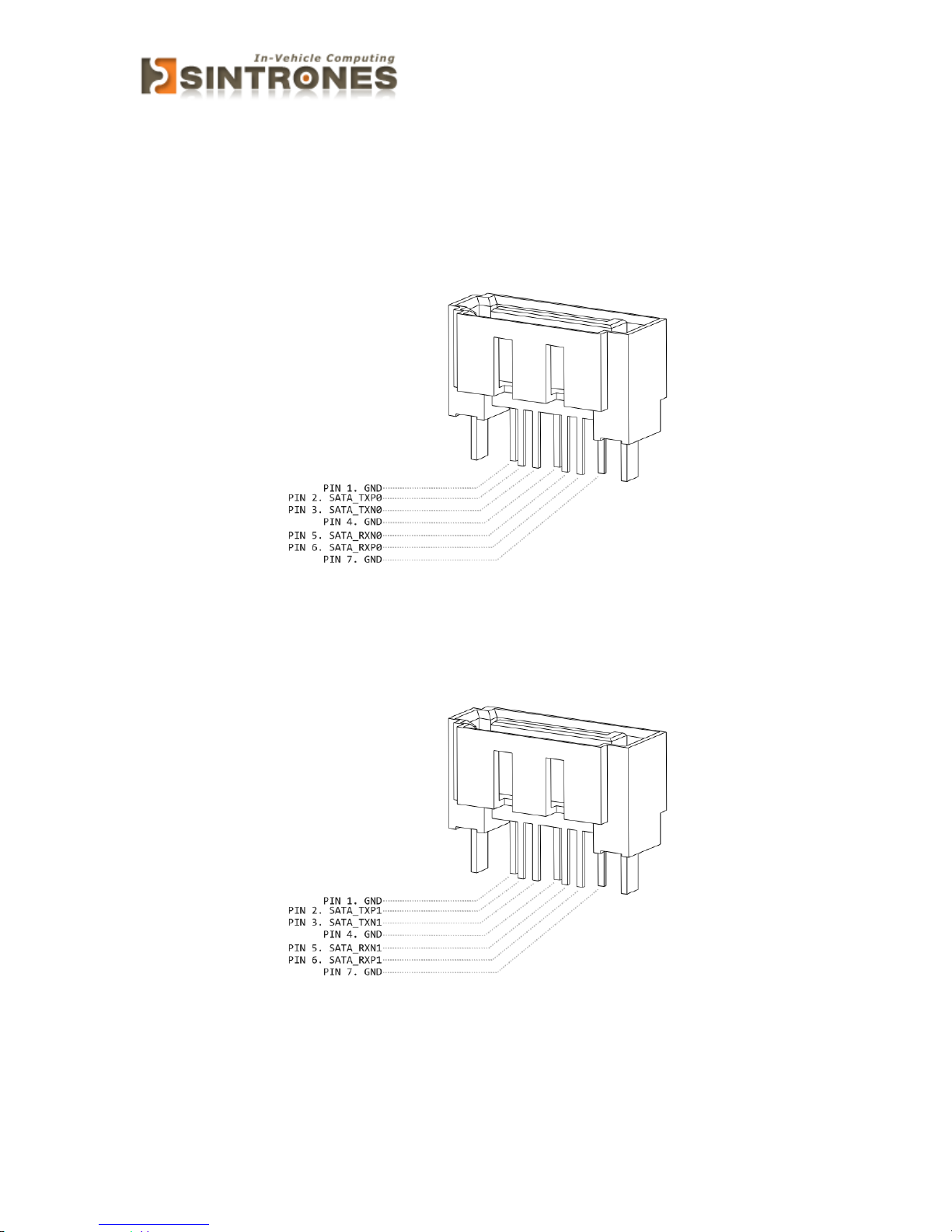
SATA Connector
Connector location: SATA1
Connector size: 1 X 7 7Pin
Connector type: SATA 1.27mm-M-180D
Connector location: SATA2
Connector size: 1 X 7 7Pin
Connector type: SATA 1.27mm-M-180D
Page 18

VBOX-3150 Manual
17
UPS Connector
Connector location: UPS1
Connector size: 1 X 5 7Pin
Connector type: WAFER 2.54mm-M-180
Page 19
VBOX-3150 Manual
18
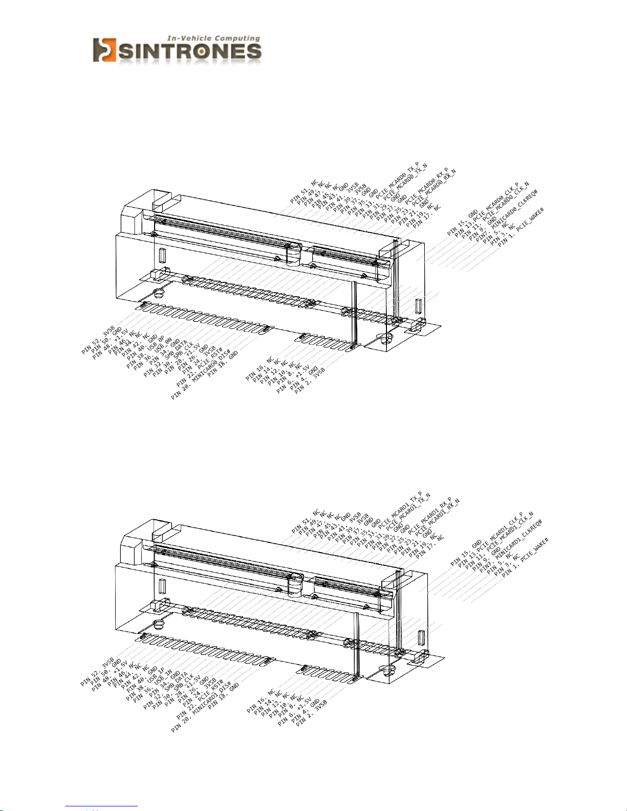
Mini PCI-E connector
Connector location: MINICARD1
Connector size: 2 X 26 = 52 Pin
Connector type: MINI PCI-E CON 9.2mmH
Connector location: MINICARD2
Connector size: 2 X 26 = 52 Pin
Connector type: MINI PCI-E CON 9.2mmH
Page 20
VBOX-3150 Manual
19
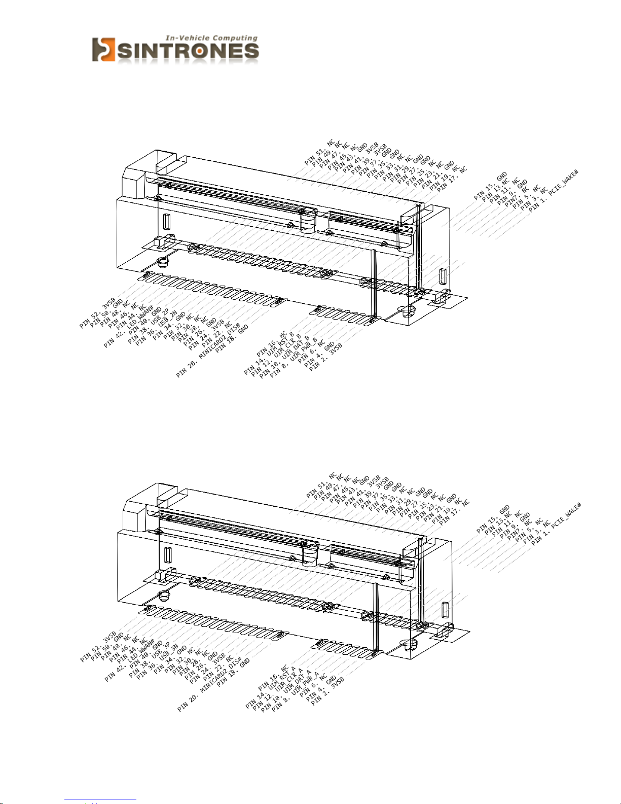
Connector location: MINICARD3
Connector size: 2 X 26 = 52 Pin
Connector type: MINI PCI-E CON 9.2mmH
Connector location: MINICARD4
Connector size: 2 X 26 = 52 Pin
Connector type: MINI PCI-E CON 9.2mmH
Page 21
VBOX-3150 Manual
20
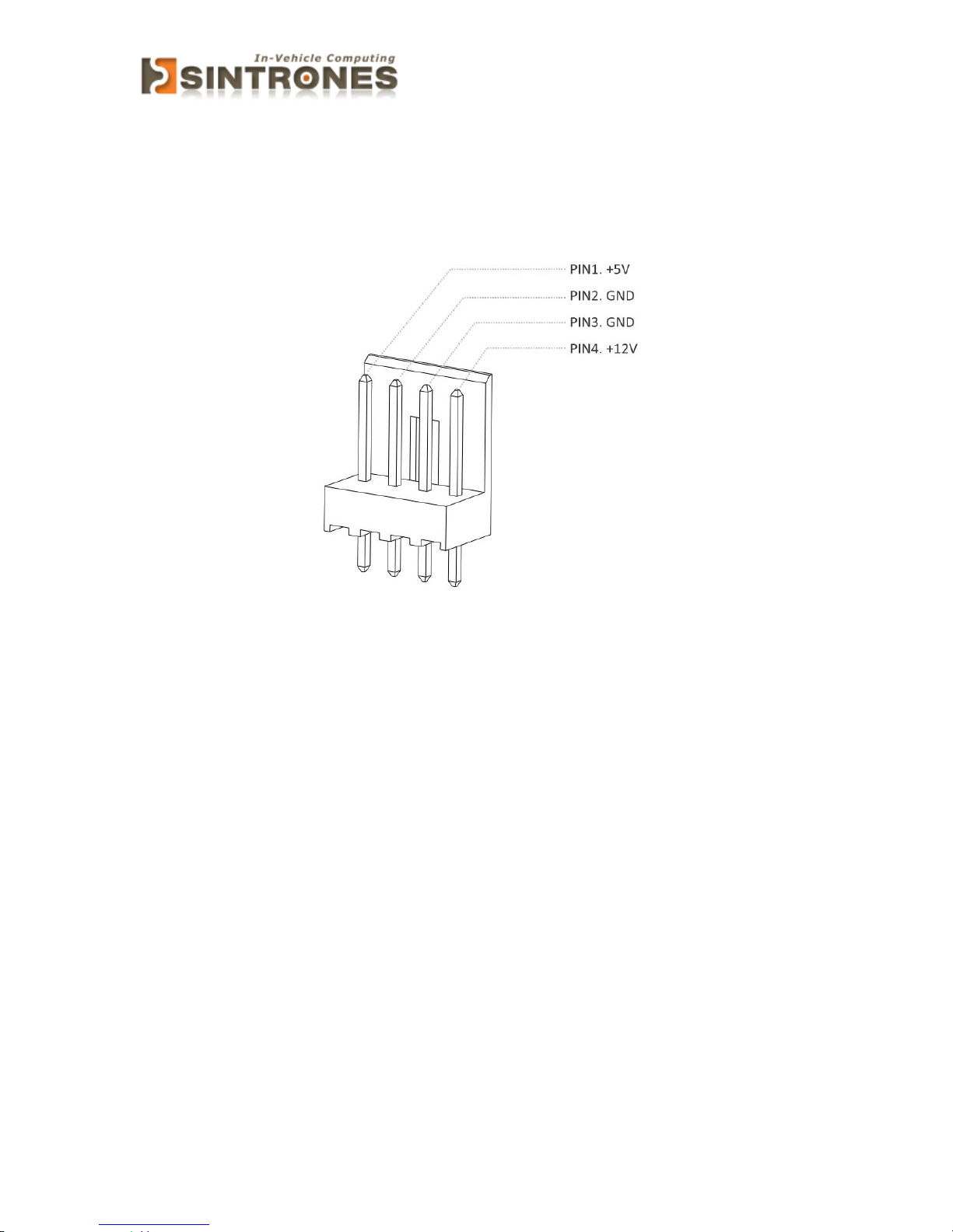
SATA Power Connector
Connector location: SPWR1/ SPWR2
Connector size: 1 X 4 = 4 Pin
Connector type: WAFER 2.54mm-M-180
Page 22
VBOX-3150 Manual
21
EXTERNAL CONNECTOR SPECIFICATION
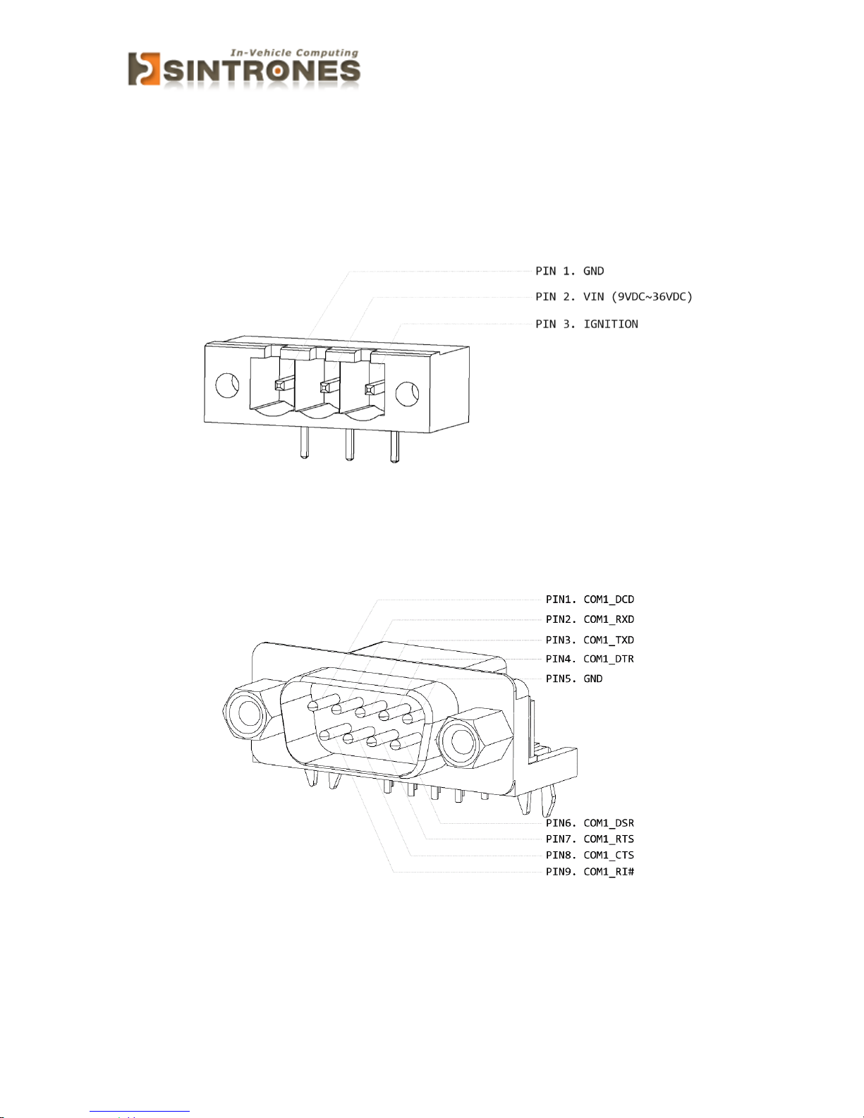
Power Input connector
Connector location: PWRIN1
Connector size: 1 X 3 = 3 Pin
Connector type: Terminal block 3PIN pitch :5.08mm
COM connector
Connector location: COM1
Connector size: 9 Pin
Connector type: DSUB
Page 23
VBOX-3150 Manual
22
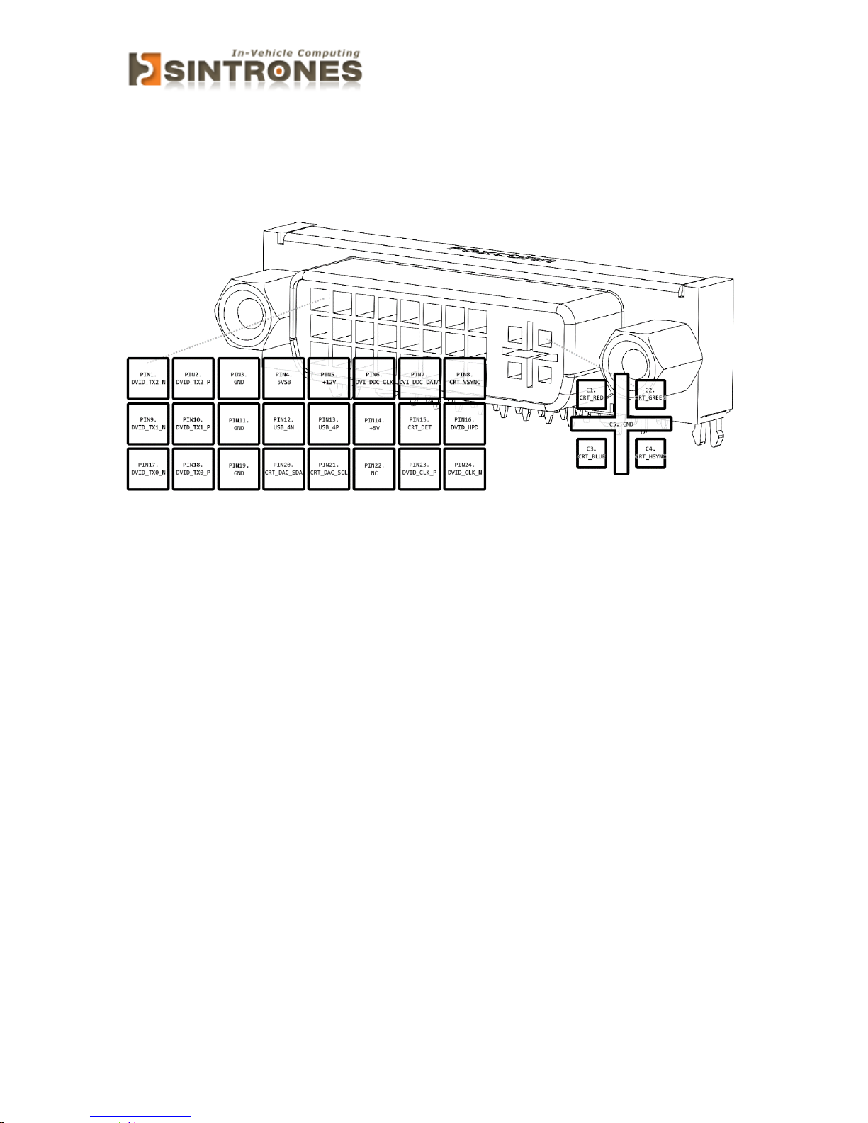
DVI-I connector
Connector location: DVI-I1
Connector size: 29 Pin
Connector type: DVI-I
Page 24
VBOX-3150 Manual
23
SYSTEM INSTALLATION
System Introduction
Page 25
VBOX-3150 Manual
24
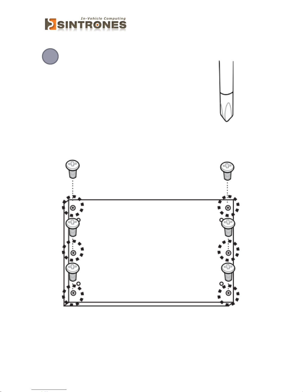
Opening Chassis
Remove the six screws on the Back Cover as figure 1.
1
Page 26
VBOX-3150 Manual
25
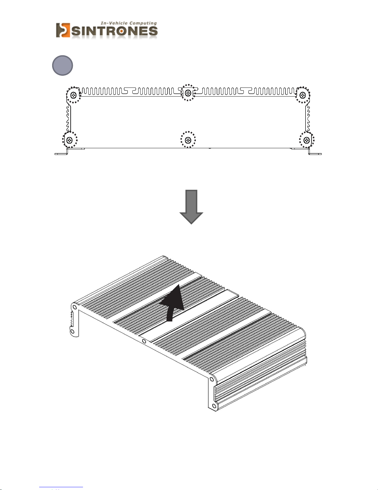
Remove the screws on the Front Panel (six screws) and Rear Panel (six
screws) and open the Top Cover as figure 2.
2
Front Panel/Rear Panel figure
Page 27
VBOX-3150 Manual
26
Installing SSD card
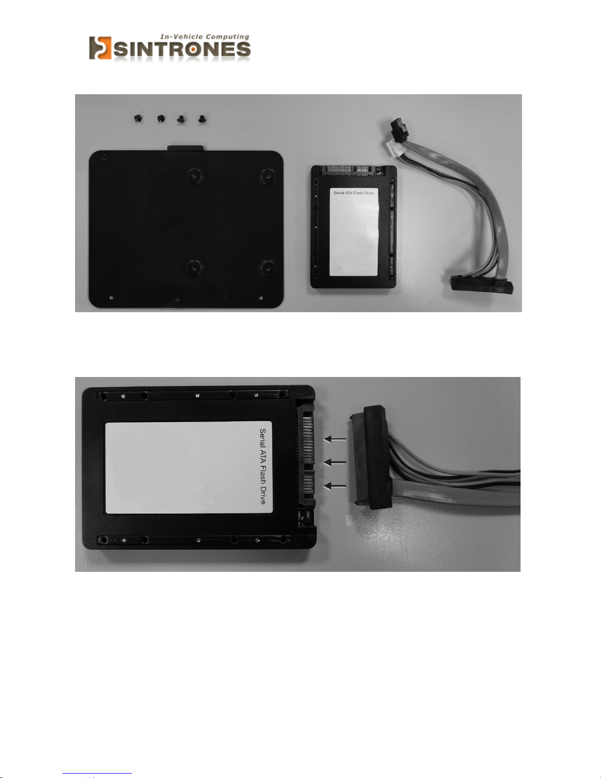
Please have screws (x4), bottom plate, SSD card and connect cable ready.
Connect SSD card and cable.
Page 28
VBOX-3150 Manual
27
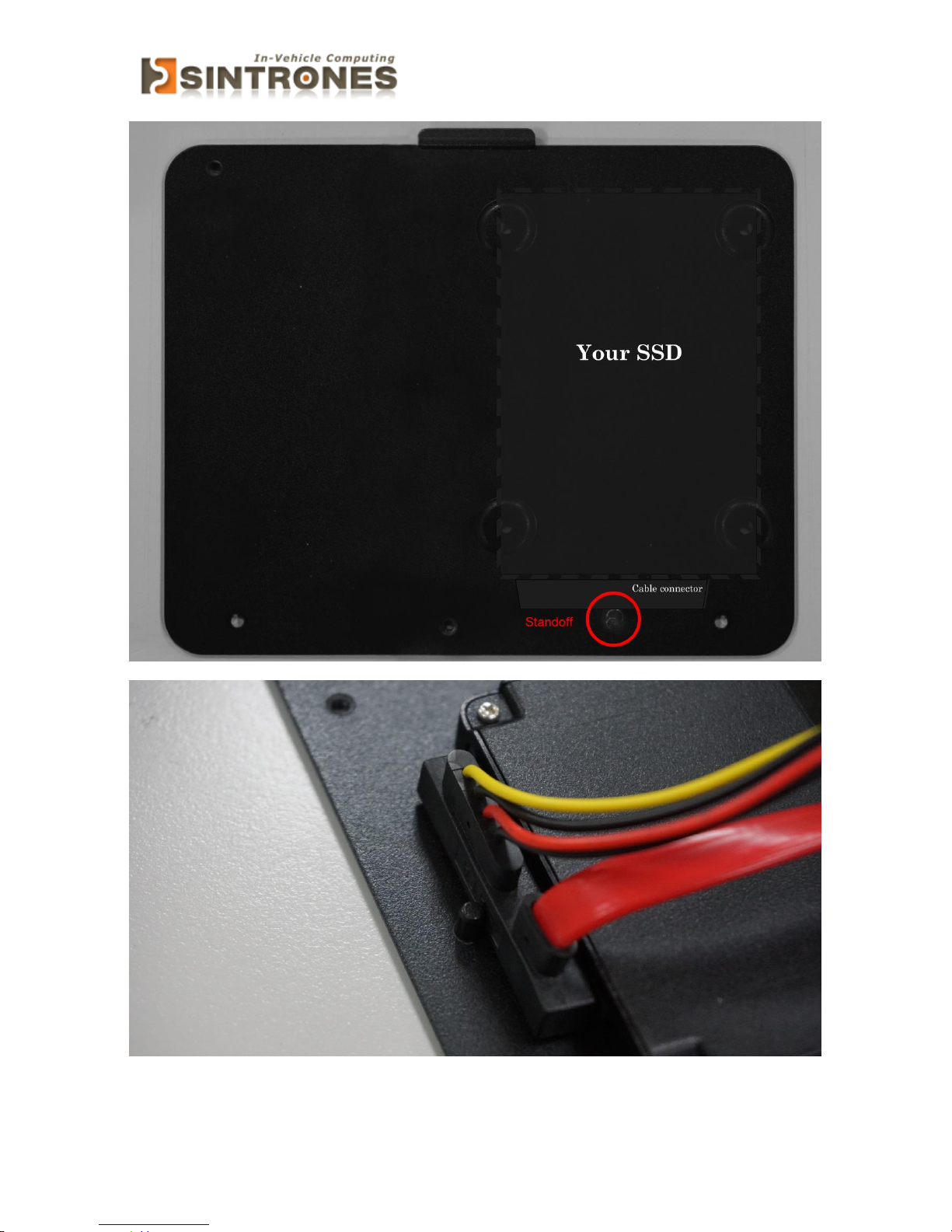
Secure SSD card onto bottom plate with screws (x4) at the side of standoff.
Page 29
VBOX-3150 Manual
28
Installing Memory
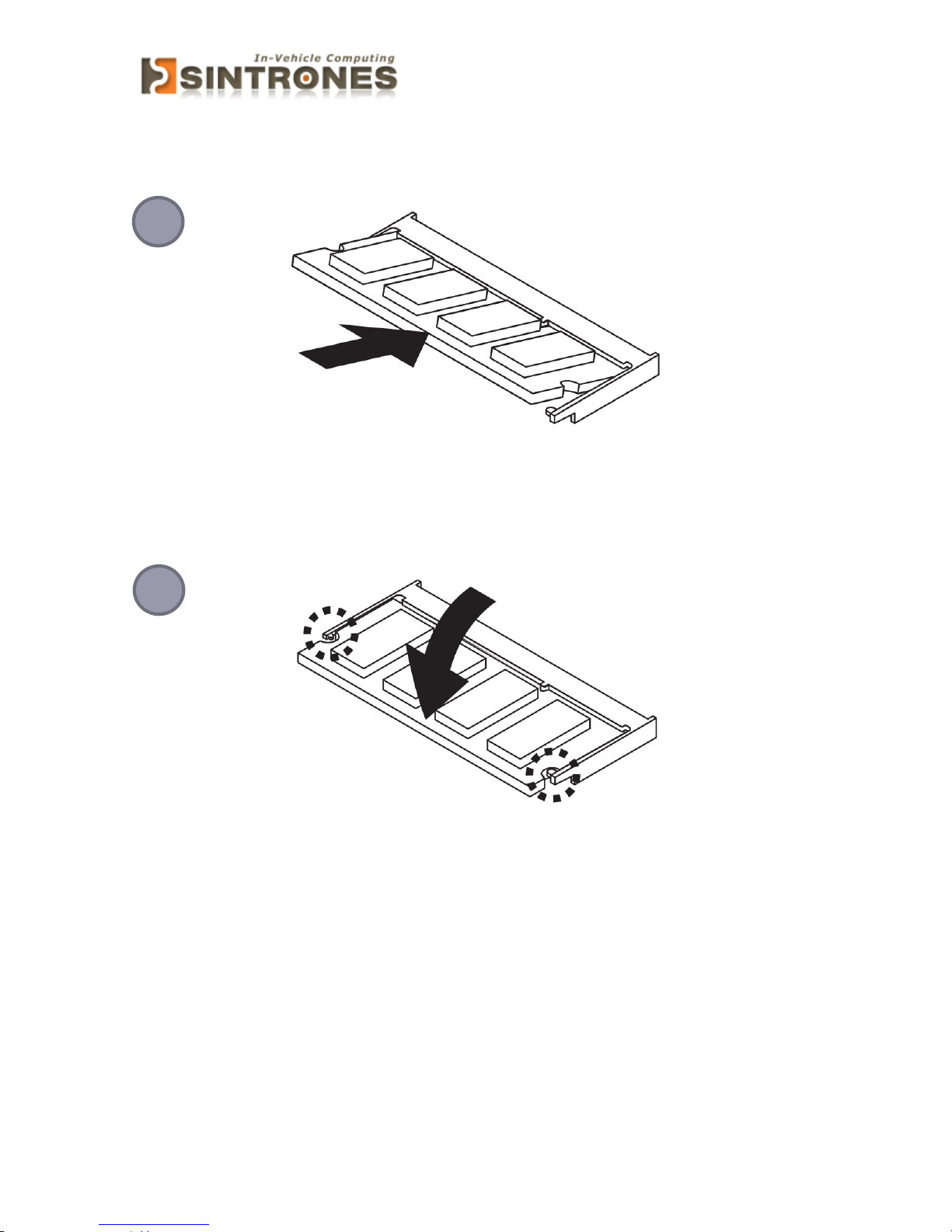
Hold the Memory with its notch aligned with the Memory socket of the board and
insert it at a 30-degree angle into the socket as figure 1.
Press down on the Memory so that the tabs of the socket lock on both sides of the
module as figure 2.
2
1
Page 30
VBOX-3150 Manual
29
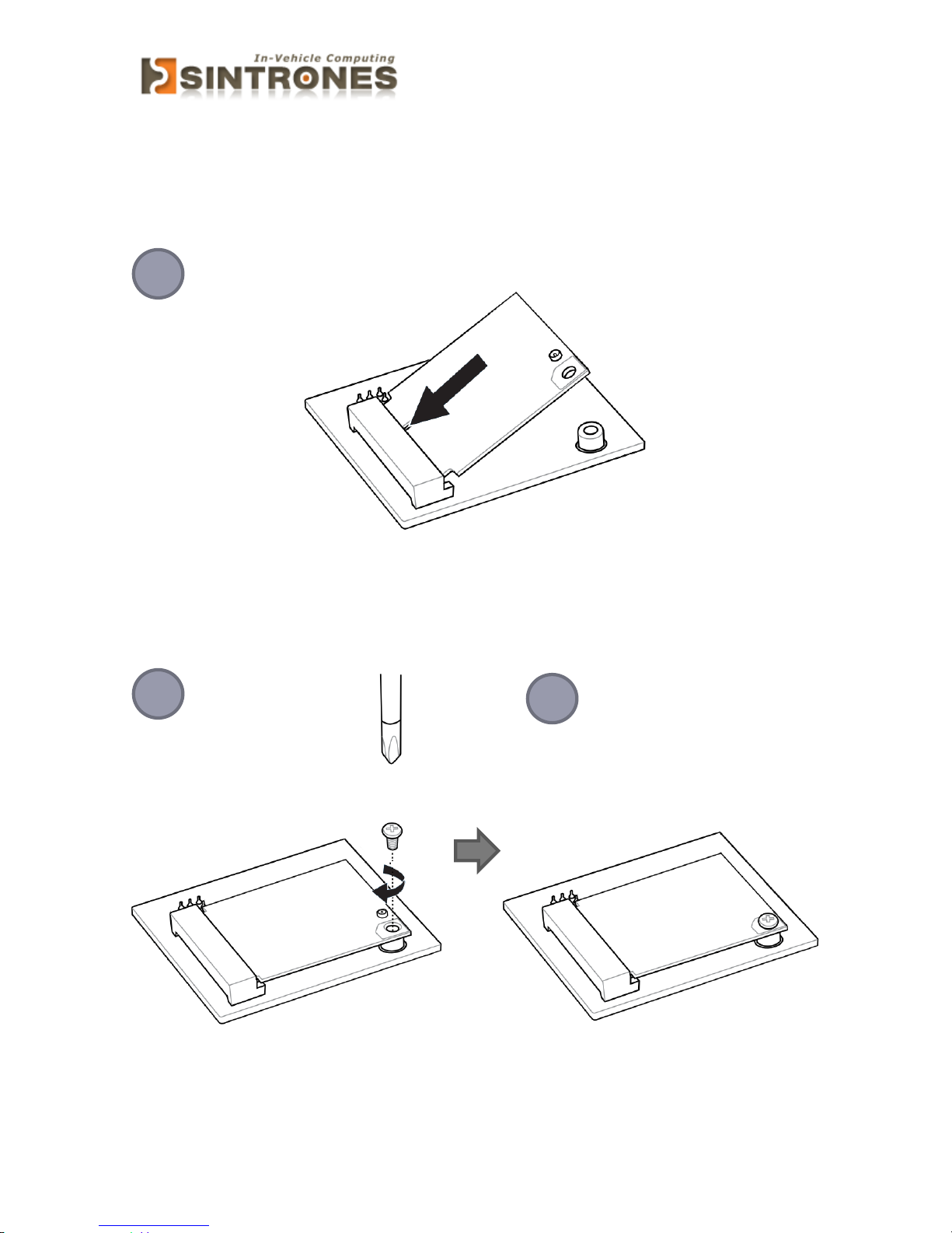
Installing MINI PCIe Expansion Card (MINICARD1)
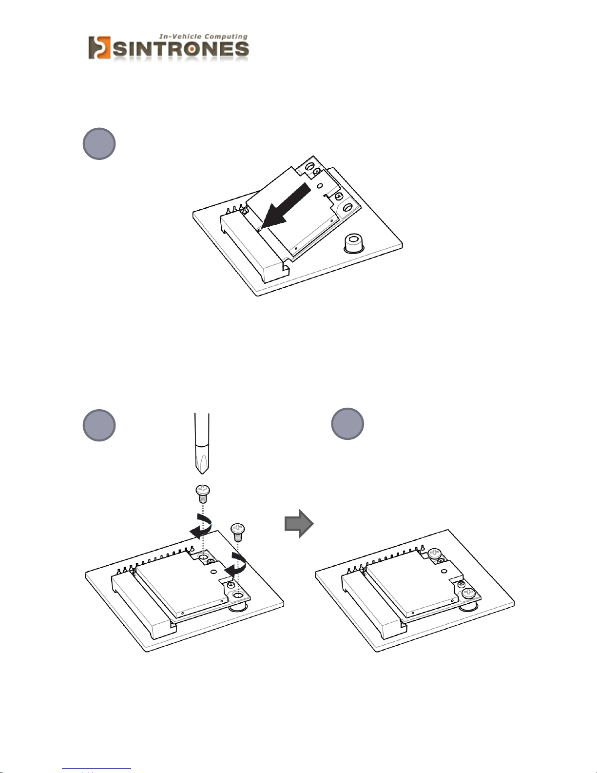
Hold the Module with its notch aligned with the socket of the board and insert it at a
30-degree angle into the socket as shown in the picture.
Secure the card with screw(s) as figure 2 and finish as figure 3.
1 2 3
Page 31
VBOX-3150 Manual
30
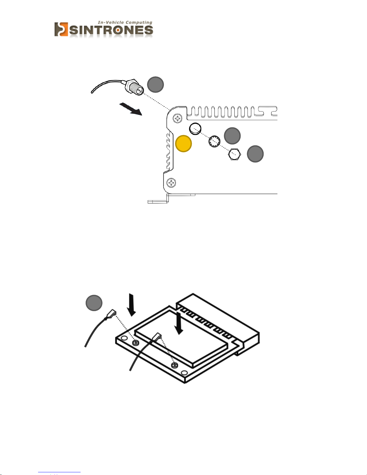
Installing MINI PCIe Expansion Card (MINICARD2, 3, 4)
Hold the Module with its notch aligned with the socket of the board and insert it at a
30-degree angle into the socket as shown in the picture.
Secure the card with screw(s) as figure 2 and finish as figure 3.
1 2 3
Page 32
VBOX-3150 Manual
31
Installing Internal Antenna Cable
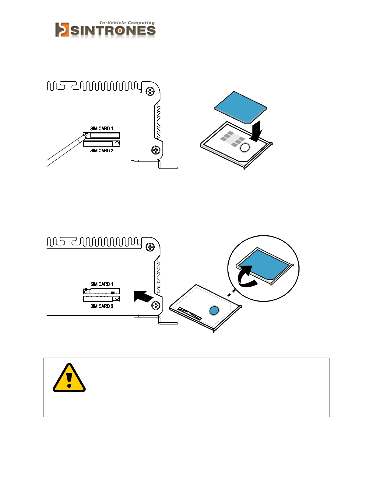
Take the SMA Connector (A) and plug into IO Panel (D). Put the Washer(B) into the
SMA Connector (A), then put the O-ring (C) to SMA Connector (A) and tighten as
shown in the picture.
Take the Ipex Connector (A) and press on the Wi-Fi module/3G module/ GPS module
(GPS, only support passive Antenna)
B
C
D
Page 33
VBOX-3150 Manual
32
Installing SIM Card
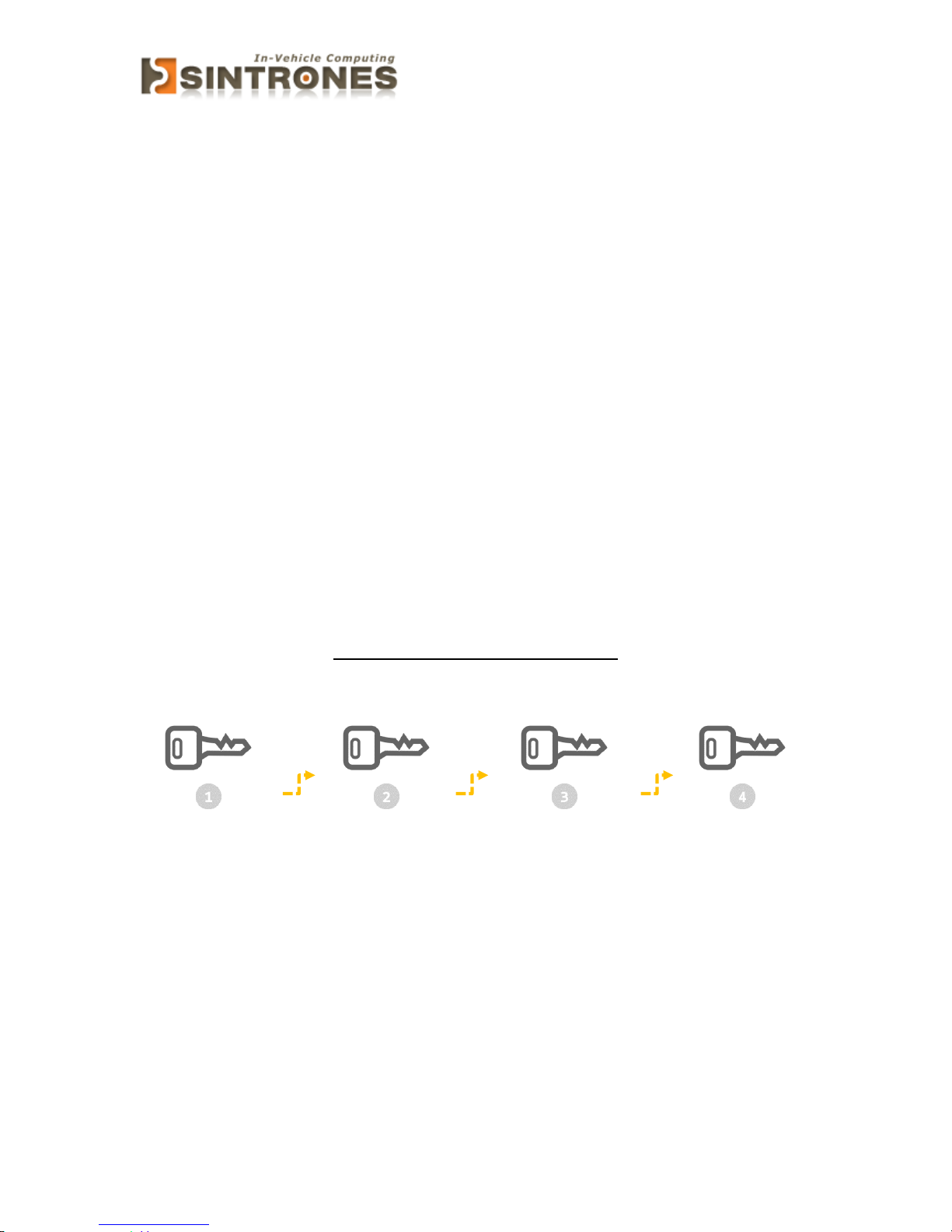
Use thin stick to push the button, then take the holder and put your SIM Card into
the it.
Take the SIM card holder and Insert it into the socket
Attention:
Please cut the main power when you insert the SIM, otherwise the
SIM card will be not detected.
Page 34
VBOX-3150 Manual
33
SYSTEM RESOURCE
Ignition Power Management Quick Guide
Startup/shutdown conditions from the IGNITION signal:
IGNITION startup signal must be valid during 3 sec. (anti noise protection).
IGNITION shutdown – IGNITION signal must be inactive during 3 Sec, then PIC
controller initiate Power Button signal (OS must be set to shutdown from the
Power Button). It generates Main Button shutdown event and then goes to
complete power off.
Typically, the system can start only from IGNITION signal, because startup PIC
controller is disconnected from the power source.
The system can be switched off from:
Power IGNITION OFF signal.
ACPI OS shutdown
Power Button – generate ACPI event (OS dependent).
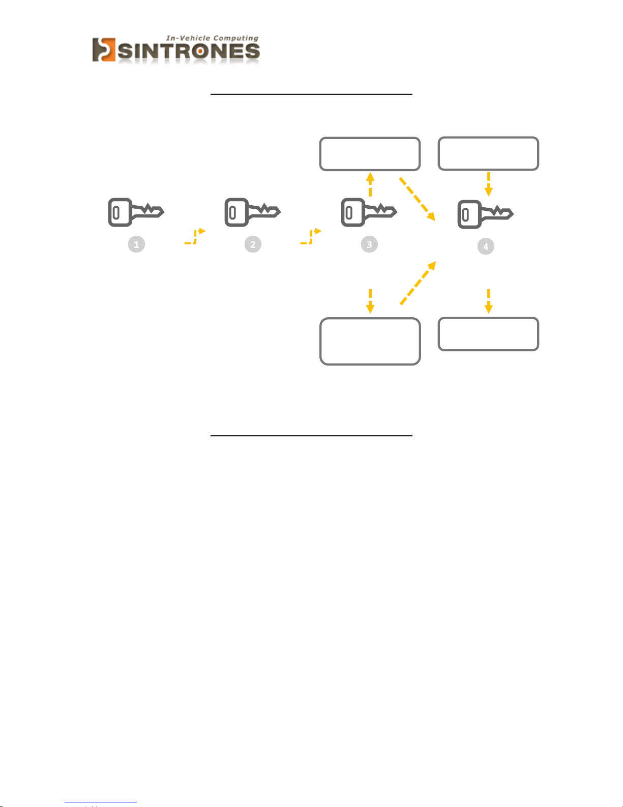
Power Ignition Startup Procedure
12V or 24V
Power Input
Check IGN Status
IGN on (High) more
than 3sec Status
System Turn on
Page 35
VBOX-3150 Manual
34
Power Ignition Shutdown Procedure
Delay Time Off
Delay 3 Sec
Shutdown from OS
& IGN off
Check IGN
Status
IGN off (Low)
Check Delay Time
On / Off
OS Shutdown System
Delay Time On 0-99
minutes
Setting by Software
3 sec later
System Power off
Power Ignition Shutdown Procedure
Power Management
Power-off delay time is selectable by Software to disable and enable in 0-99
minutes
Ignition On/Off status detectable by SW
If the ignition is off and the system is still on after 3 Sec, VBOX-3150 will shut
down automatically.
If the ignition is turned on again and the power-off delay is in progress, VBOX-
3150 will cancel the delay function and will continue to operate normally.
If the ignition is turned on again and the power-off delay ended, VBOX-3150 will shut
down completely will power-on again automatically.
Page 36
VBOX-3150 Manual
35
GPIO & Delay Time Setting
GPIO and Ignition Control Register
The General Purpose I/O is an interface available on some devices. These can read
digital signals from other parts of a circuit, or output to control other devices. At
GPIO control register, the GPI is use to receive data, the GPO is set data to send.
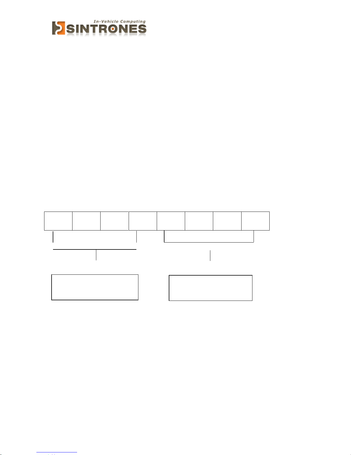
I/O port: 0xA35 (base address) for Control Register (Read 0xA2h / Write 0xA1h)
0xA36 (base address) for Control Data Value
Debug Command Line
- O A35 A1
- O A36 0F // Set Bit 4-7 to Low
7 6 5 4 3 2 1 0
DO4
DO3
DO2
DO1
DI4
DI3
DI2
DI1
0 = DI is low *
1 = DI is high
0 = DO is low
1 = DO is high *
Page 37
VBOX-3150 Manual
36
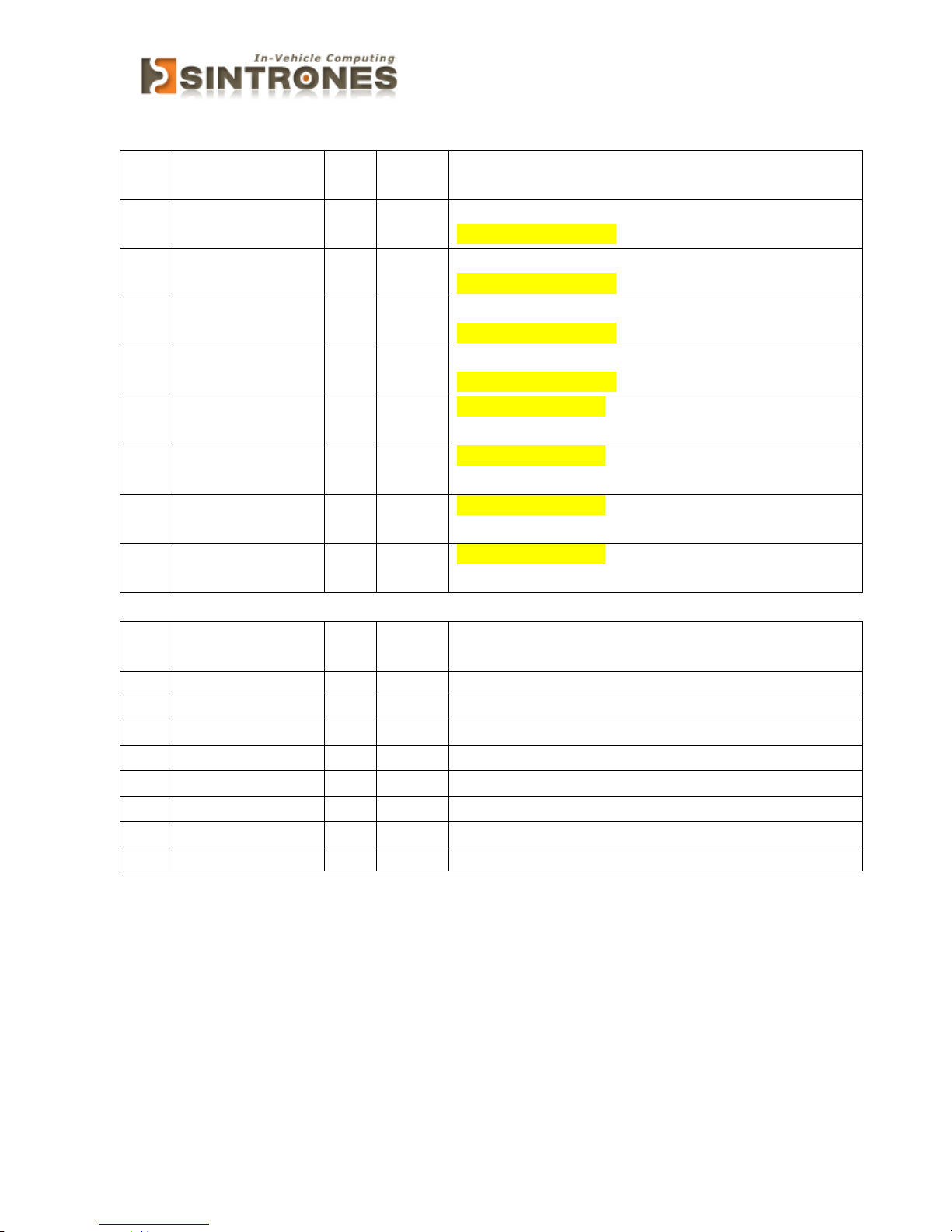
GPIO5 Output Enable Register – Index A0h
Bit
Name
R/W
Defaul
t
Description
7
GPIO57_OE
R/W
0
0 : GPIO57 is input
1 : GPIO57 is output
6
GPIO56_OE
R/W
0
0 : GPIO56 is input
1 : GPIO56 is output
5
GPIO55_OE
R/W
0
0 : GPIO55 is input
1 : GPIO55 is output
4
GPIO54_OE
R/W
0
0 : GPIO54 is input
1 : GPIO54 is output
3
GPIO53_OE
R/W
0
0 : GPIO53 is input
1 : GPIO53 is output
2
GPIO52_OE
R/W
0
0 : GPIO52 is input
1 : GPIO52 is output
1
GPIO51_OE
R/W
0
0 : GPIO51 is input
1 : GPIO51 is output
0
GPIO50_OE
R/W
0
0 : GPIO50 is input
1 : GPIO50 is output
GPIO5 Output Data Register – Index A1h
Bit
Name
R/W
Defaul
t
Description
7
GPIO57_DATA
R/W
1
GPIO57 output data in output mode.
6
GPIO56_DATA
R/W
1
GPIO56 output data in output mode.
5
GPIO55_DATA
R/W
1
GPIO55 output data in output mode.
4
GPIO54_DATA
R/W
1
GPIO54 output data in output mode.
3
GPIO53_DATA
R/W
1
GPIO53 output data in output mode.
2
GPIO52_DATA
R/W
1
GPIO52 output data in output mode.
1
GPIO51_DATA
R/W
1
GPIO51 output data in output mode.
0
GPIO50_DATA
R/W
1
GPIO50 output data in output mode.
Page 38
VBOX-3150 Manual
37
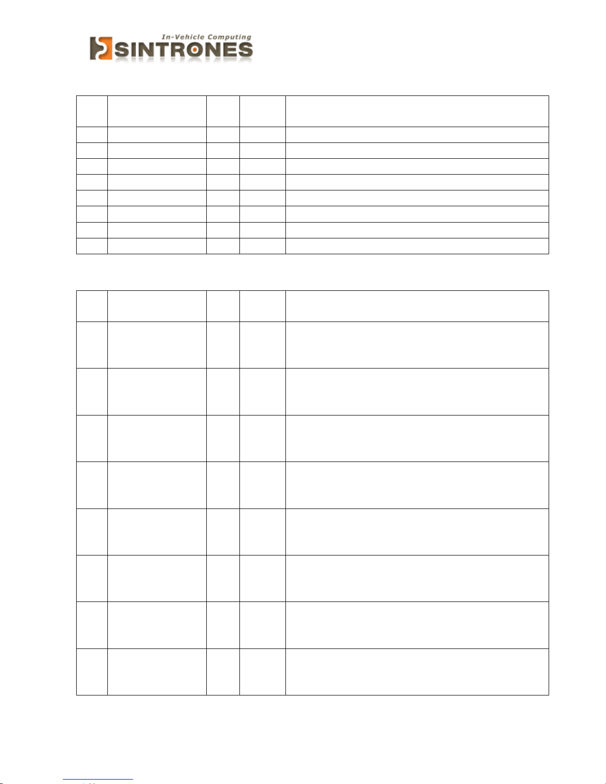
GPIO5 Pin Status Register – Index A2h
Bit
Name
R/W
Defaul
t
Description
7
GPIO57_ST
R 1 GPIO57 pin status.
6
GPIO56_ST
R 1 GPIO56 pin status.
5
GPIO55_ST
R 1 GPIO55 pin status.
4
GPIO54_ST
R 1 GPIO54 pin status.
3
GPIO53_ST
R 1 GPIO53 pin status.
2
GPIO52_ST
R 1 GPIO52 pin status.
1
GPIO51_ST
R 1 GPIO51 pin status.
0
GPIO50_ST
R 1 GPIO50 pin status.
GPIO5 Drive Enable Register – Index A3h
Bit
Name
R/W
Defaul
t
Description
7
GPIO57_DRV_E
NST
R/W
0
GPIO57 Drive Enable
0 : GPIO57 is open drain.
1 : GPIO57 is push pull.
6
GPIO56_DRV_E
NST
R/W
0
GPIO57 Drive Enable
0 : GPIO56 is open drain.
1 : GPIO56 is push pull.
5
GPIO55_DRV_E
NST
R/W
0
GPIO57 Drive Enable
0 : GPIO55 is open drain.
1 : GPIO55 is push pull.
4
GPIO54_DRV_E
NST
R/W
0
GPIO57 Drive Enable
0 : GPIO54 is open drain.
1 : GPIO54 is push pull.
3
GPIO53_DRV_E
NST
R/W
0
GPIO57 Drive Enable
0 : GPIO53 is open drain.
1 : GPIO53 is push pull.
2
GPIO52_DRV_E
NST
R/W
0
GPIO57 Drive Enable
0 : GPIO52 is open drain.
1 : GPIO52 is push pull.
1
GPIO51_DRV_E
NST
R/W
0
GPIO57 Drive Enable
0 : GPIO51 is open drain.
1 : GPIO51 is push pull.
0
GPIO50_DRV_E
NST
R/W
0
GPIO57 Drive Enable
0 : GPIO50 is open drain.
1 : GPIO50 is push pull.
Page 39
VBOX-3150 Manual
38
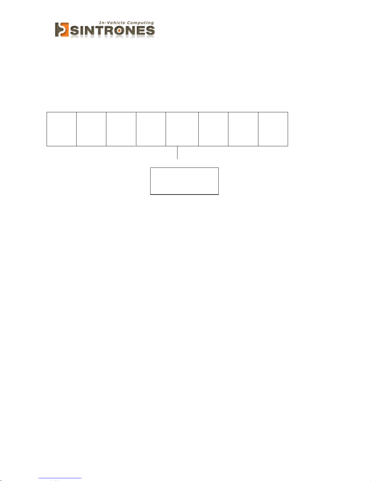
I/O port: I/O port:
0xA35 (base address) for Control Register (Read 0xF2h bit 3)
0xA36 (base address) for Control Data Value
7 6 5 4 3 2 1 0
X X X
X
Ignition
Status
X
X
X
Debug Command Line
- O A35 F2
- I A36 // Check Bit 3 Status
0 = Ignition off
1 = Ignition on
 Loading...