

Page 1
User’s manual
EMBEDDED COMPUTING
Page 2

SBOX-2320 Manual
1
SINTRONES® Technology Corp.
User Manual
Copyright
©2009 by SINTRONES® Technology Corp. All Rights Reserved.
No part of this publication may be reproduced, transcribed, stored in a retrieval system,
translated into any language, or transmitted in any form or by any means such as
electronic, mechanical, magnetic, optical, chemical, photocopy, manual, or otherwise,
without prior written permission from SINTRONES® Technology Corp.
Other brands and product names used herein are for identification purposes only and
may be trademarks of their respective owners.
Disclaimer
SINTRONES® Technology Corp. shall not be liable for any incidental or consequential
damages resulting from the performance or use of this product.
SINTRONES® Technology Corp. makes no representation or warranty regarding the
content of this manual. Information in this manual had been carefully checked for
accuracy; however, no guarantee is given as to the correctness of the contents. For
continuing product improvement, SINTRONES® Technology Corp. reserves the right to
revise the manual or make changes to the specifications of this product at any time
without notice and obligation to any person or entity regarding such change. The
information contained in this manual is provided for general use by customers.
This device complies to Part 15 of the FCC Rules. Operation is subject to the following
two conditions:
1. This device may not cause harmful interference.
2. This device must withstand any background interference including those that may
cause undesired operation.
Page 3

SBOX-2320 Manual
2
Safety Information
Read the following precautions before setting up a SINTRONES Product.
Electrical safety
To prevent electrical shock hazard, disconnect the power cable from the electrical
outlet before relocating the system.
When adding or removing devices to or from the system, ensure that the power
cables for the devices are unplugged before the signal cables are connected. If
possible, disconnect all power cables from the existing system before you add a
device.
Before connecting or removing signal cables from the motherboard, ensure that
all power cables are unplugged.
Seek professional assistance before using an adapter or extension cord. These
devices could interrupt the grounding circuit.
Make sure that your power supply is set to the correct voltage in your area. If you
are not sure about the voltage of the electrical outlet you are using, contact your
local power company.
If the power supply is broken, do not try to fix it by yourself. Contact a qualified
service technician or your retailer.
Operation safety
Before installing the motherboard and adding devices on it, carefully read all the
manuals that came with the package.
Before using the product, make sure all cables are correctly connected and the
power cables are not damaged. If you detect any damage, contact your dealer
immediately.
To avoid short circuits, keep paper clips, screws, and staples away from
connectors, slots, sockets and circuitry.
Avoid dust, humidity, and temperature extremes. Do not place the product in any
area where it may become wet.
Place the product on a stable surface.
If you encounter technical problems with the product, contact a qualified service
technician or your retailer.
Page 4

SBOX-2320 Manual
3
CAUTION
Incorrectly replacing the battery may damage this computer. Replace only with the
same or its equivalent as recommended by SINTRONES® Technology Corp. Dispose
used battery according to the manufacturer's instructions.
Technical Support
Please do not hesitate to call or e-mail our customer service when you still cannot fix
the problems.
Tel : +886-2-82280101
Fax : +886-2-82280100
E-mail : [email protected]
Website : www.sintrones.com
Page 5

SBOX-2320 Manual
4
Content
1. Introduction ................................................................................................................................ 6
Specification.............................................................................................................................. 6
2. Illustration (MB/System) .............................................................................................................. 8
Mainboard ................................................................................................................................. 8
System ...................................................................................................................................... 9
3. Architecture ................................ ................................ ................................ .............................. 10
4. Principal component Specification ............................................................................................... 10
CPU ....................................................................................................................................... 10
5. boot up the system ..................................................................................................................... 11
6. Internal Connector ..................................................................................................................... 12
VGA Connector ....................................................................................................................... 12
USB Connector ........................................................................................................................ 12
GPIO Connector ...................................................................................................................... 13
UART and GPIO Connector ...................................................................................................... 14
LED Connector ........................................................................................................................ 14
COM Port Connector ................................................................................................................ 15
AUDIO Connector ................................................................................................................... 17
SATA Connector ...................................................................................................................... 17
Mini PCI-E connector ............................................................................................................... 18
Power Input Connector ............................................................................................................. 19
SATA Power Connector ............................................................................................................ 20
7. External connector specification .................................................................................................. 21
USB Connector ........................................................................................................................ 21
LAN connector ........................................................................................................................ 21
DVI-I connector ....................................................................................................................... 22
HDMI connector ...................................................................................................................... 23
Page 6

SBOX-2320 Manual
5
AUDIO connector .................................................................................................................... 23
8. System Introduction ................................................................................................................... 24
I/O Panel ................................................................................................................................. 24
Opening Chassis ...................................................................................................................... 25
Installing Memory .................................................................................................................... 27
Installing MINI PCIe Expansion Card (MINICARD1) .................................................................. 28
Installing MINI PCIe Expansion Card (MINICARD2) .................................................................. 29
Installing Internal Antenna Cable ............................................................................................... 30
Installing SIM Card ................................ ................................ ................................ .................. 31
9. System Resource ....................................................................................................................... 32
10. BIOS........................................................................................................................................ 36
Enter The BIOS ....................................................................................................................... 36
Main ....................................................................................................................................... 38
Advanced ............................................................................................................................... 39
Chipset ................................................................................................................................ ... 46
Boot ....................................................................................................................................... 50
Security .................................................................................................................................. 52
Exit ........................................................................................................................................ 53
11. Packing List .............................................................................................................................. 54
System .................................................................................................................................... 54
Accessory ............................................................................................................................... 54
Page 7
SBOX-2320 Manual
6
INTRODUCTION
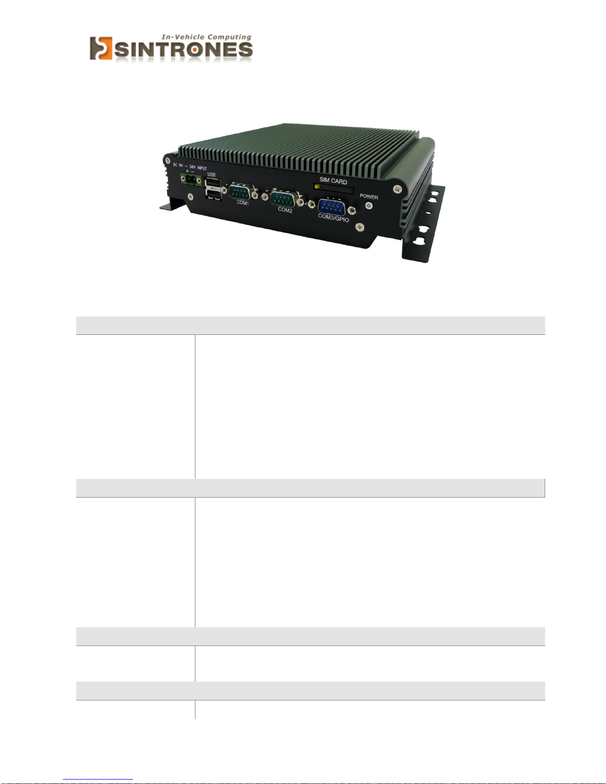
Specification
System
CPU
Intel N3710 Quad Core CPU up to 2.56HGz
Intel N3160 Quad Core CPU up to 2.24HGz
Intel N3060 Dual Core CPU up to 2.48HGz
Memory
1 x DDR3L-1600 SO-DIMM up to 8GB
Graphics
ATA
Intel HD Graphics
2 x Serial ATA ports with 6GB/s HDD Transfer Rate
LAN Chipset
2 x Intel i210-AT Gigabit Ethernet
Watchdog
1 ~ 255 Level Reset
I/O
Serial Port
2 x RS-232 Ports (2 x RS-232/422/485), Optional Max. 4 x RS-232
USB Port
2 x USB 2.0 and 2 x USB 3.0 Ports
LAN
2 x RJ45 ports for GbE
Video Port
HDMI/ DVI/ VGA (Though DVI-I), Max. 3 Display Outputs
DIO Port
4 In and 4 Out GPIO Ports (5V Level)
Audio
Line-out
Expansion Bus
3 x Mini-card Slots (1 with SIM for LTE/3G Only)
Storage
Type
1 x 2.5” Drive Bay for SATA Type Hard Disk Drive / SSD
1 x SATA DOM
Software
Operating system
Windows 7, WES 7, Windows 10, Ubuntu 14.04 above
Page 8
SBOX-2320 Manual
7
Qualification
Certifications
CE, FCC Class A
Environment
Operating Temp.
-30 ~ 60ºC (SSD), ambient w/ air
Storage Temp.
-40 ~ 85ºC
Relative Humidity
10 ~ 95% @ 40ºC (non-condensing)
Vibration (random)
DC 9-36V Input with Reverse Polarity OCP and OVP Protection
Mechanical
Construction
Aluminum Alloy
Mounting
Wall-mount, VESA-mount, Din Rail Mounting Kit
Weight
1200g (Barebone)
Dimensions
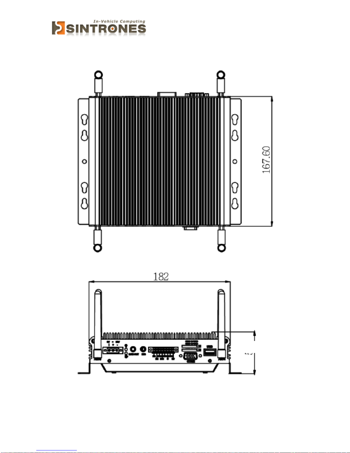
182 x 167.6 x 54 mm
Page 9
SBOX-2320 Manual
8
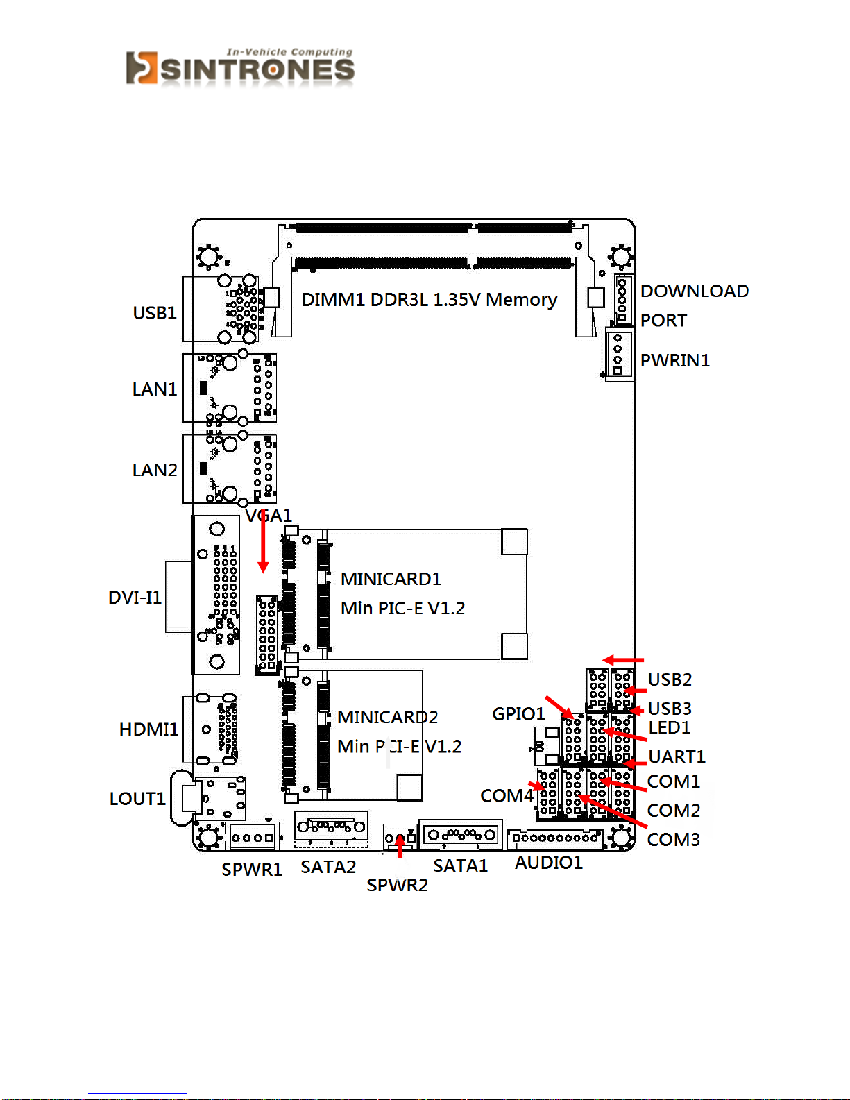
ILLUSTRATION (MB/SYSTEM)
Mainboard
Page 10
SBOX-2320 Manual
9
System
54
Page 11
SBOX-2320 Manual
10
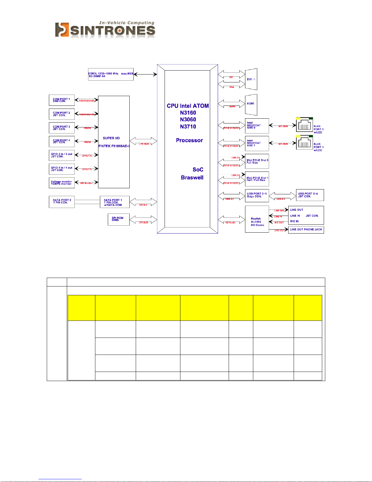
ARCHITECTURE
PRINCIPAL COMPONENT SPECIFICATION
CPU
Chip
Description
Intel
1. Power consumption:
Symbol
Processor
Number
Core
Frequency/
GHz
Thermal
Design Power
Unit
CPU Core
Cache
SOC
N3710
Up to
2.56GHz
6 W 4 Core
2M
N3160
Up to
2.24GHz
6 W 4 Core
2M
N3060
Up to
2.48GHz
6 W 2 Core
2M
Page 12
SBOX-2320 Manual
11
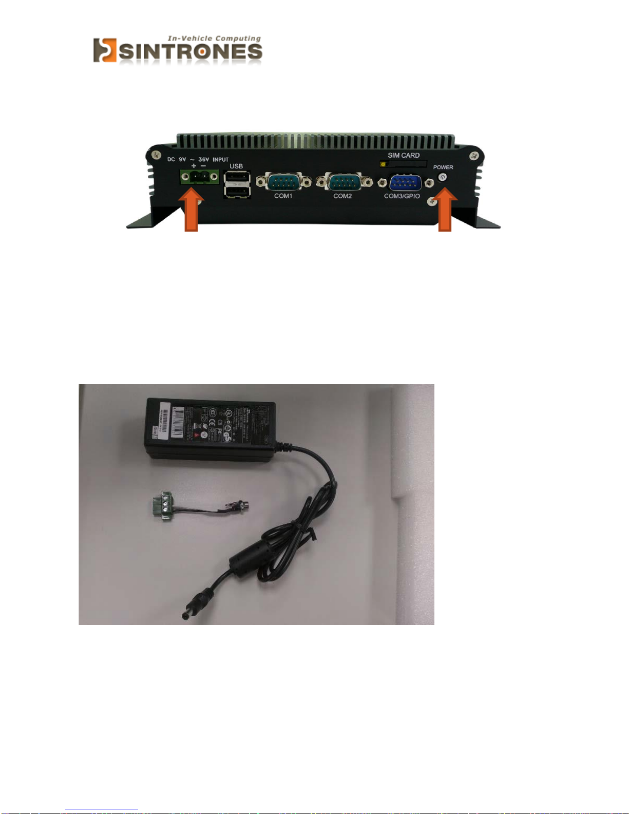
BOOT UP THE SYSTEM
1. Connect the Two Pin Terminal Block to BOX PC (Positive and Negative)
2. Press the POWER button to boot up.
Power adapter and DC Jack cable are the options
Page 13
SBOX-2320 Manual
12
INTERNAL CONNECTOR
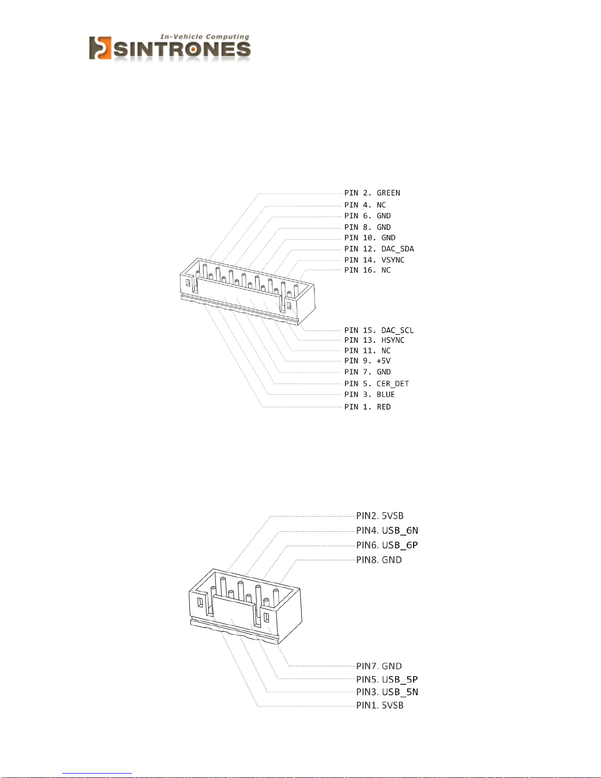
VGA Connector
Connector location: VGA1
Connector size: 2 X 8 = 16 Pin
Connector type: JST-2.0mm-M-180
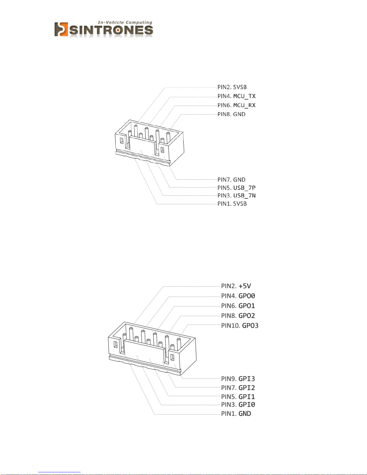
USB Connector
Connector location: USB2
Connector size: 2 X 4= 8Pin
Connector type: JST-2.0mm-M-180
Page 14
SBOX-2320 Manual
13
Connector location: USB3
Connector size: 2 X 4= 8Pin
Connector type: JST-2.0mm-M-180
GPIO Connector
Connector location: GPIO1
Connector size: 2 X 5 = 10 Pin
Connector type: JST-2.0mm-M-180
Page 15
SBOX-2320 Manual
14
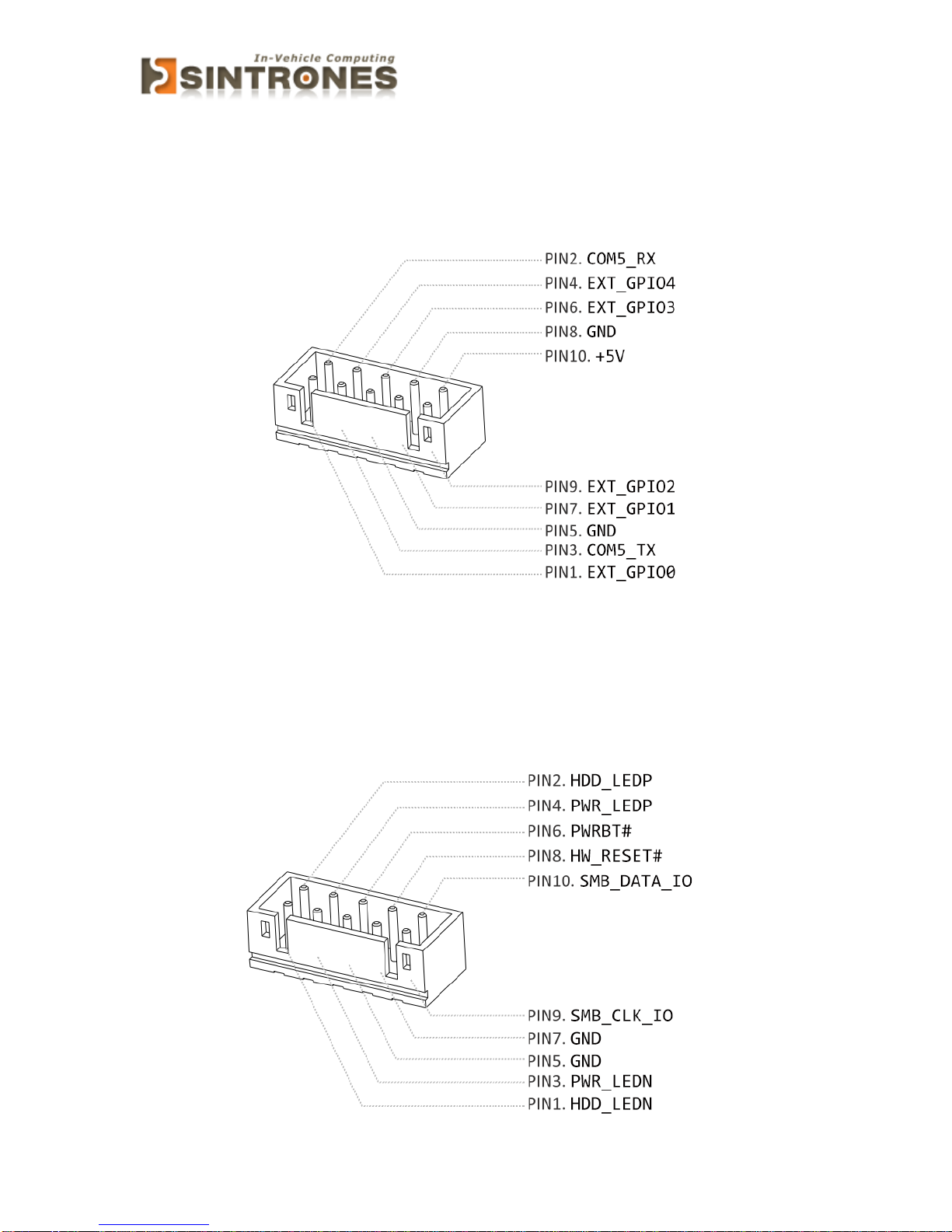
UART and GPIO Connector
Connector location: UART1
Connector size: 2 X 5 = 10 Pin
Connector type: JST-2.0mm-M-180
LED Connector
Connector location: LED1
Connector size: 2 X 5 = 10 Pin
Connector type: JST-2.0mm-M-180
Page 16
SBOX-2320 Manual
15
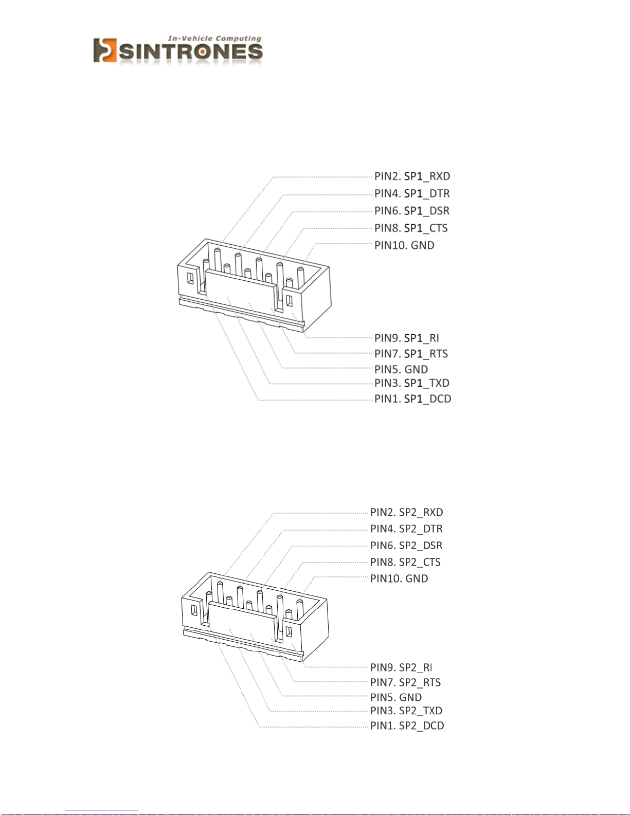
COM Port Connector
Connector location: COM1
Connector size: 2 X 5 = 10 Pin
Connector type: JST-2.0mm-M-180
Connector location: COM2
Connector size: 2 X 5 = 10 Pin
Connector type: JST-2.0mm-M-180
Page 17
SBOX-2320 Manual
16
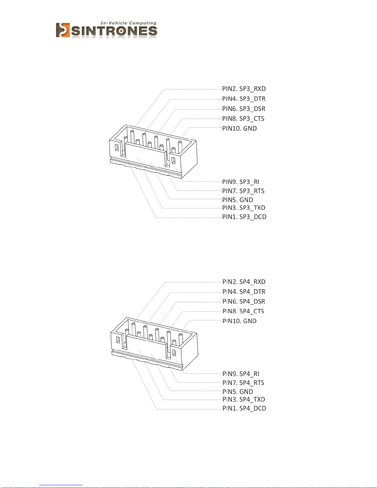
Connector location: COM3
Connector size: 2 X 5 = 10 Pin
Connector type: JST-2.0mm-M-180
Connector location: COM4
Connector size: 2 X 5 = 10 Pin
Connector type: JST-2.0mm-M-180
Page 18
SBOX-2320 Manual
17
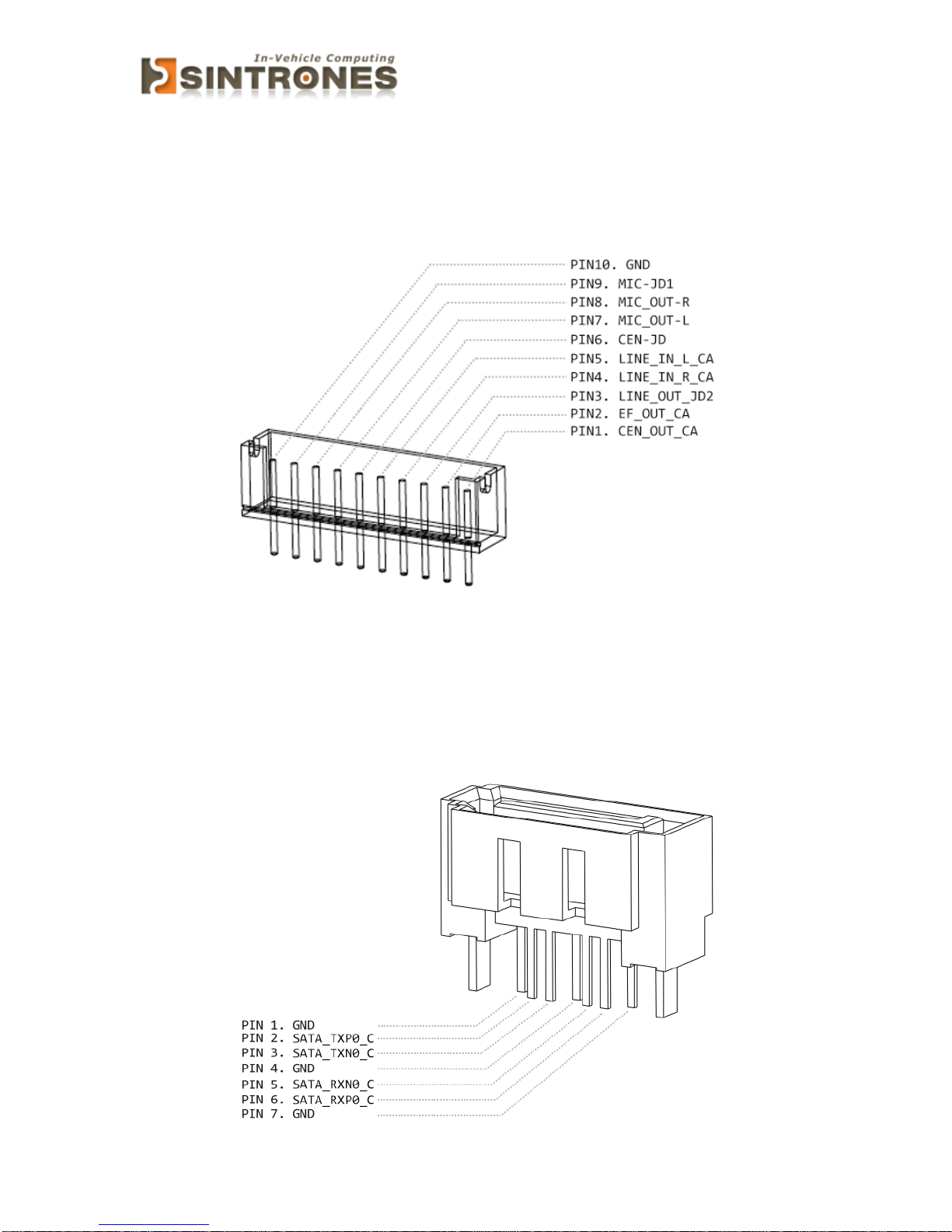
AUDIO Connector
Connector location: AUDIO1
Connector size: 1 X 10 = 10Pin
Connector type: JST-2.0mm-M-180
SATA Connector
Connector location: SATA1
Connector size: 1 X 7 = 7Pin
Connector type: SATA 1.27mm-M-180D
Page 19
SBOX-2320 Manual
18
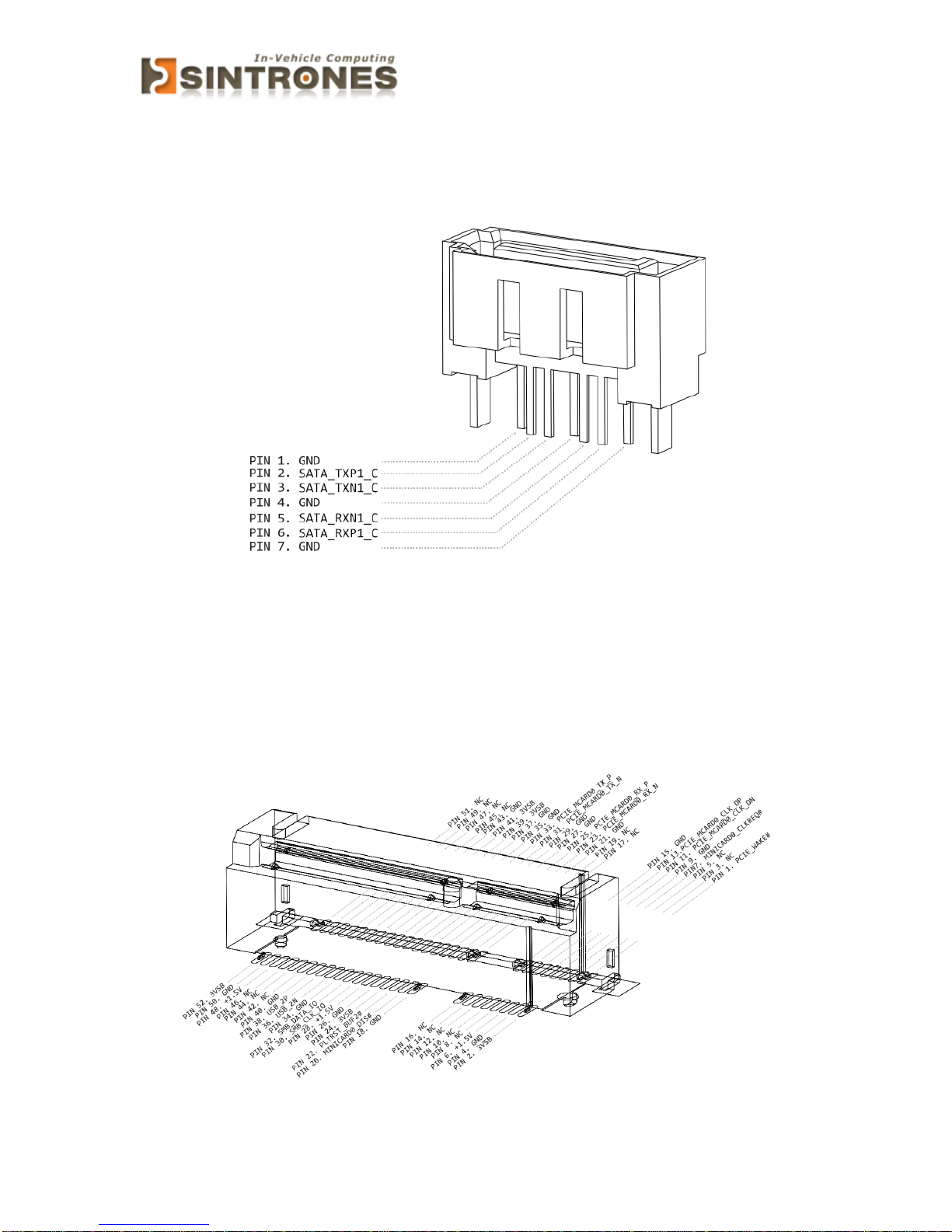
Connector location: SATA2
Connector size: 1 X 7 = 7Pin
Connector type: SATA 1.27mm-M-180D
Mini PCI-E connector
Connector location: MINICARD1
Connector size: 2 X 26 = 52 Pin
Connector type: MINI PCI-E CON 9.2mmH
Page 20
SBOX-2320 Manual
19
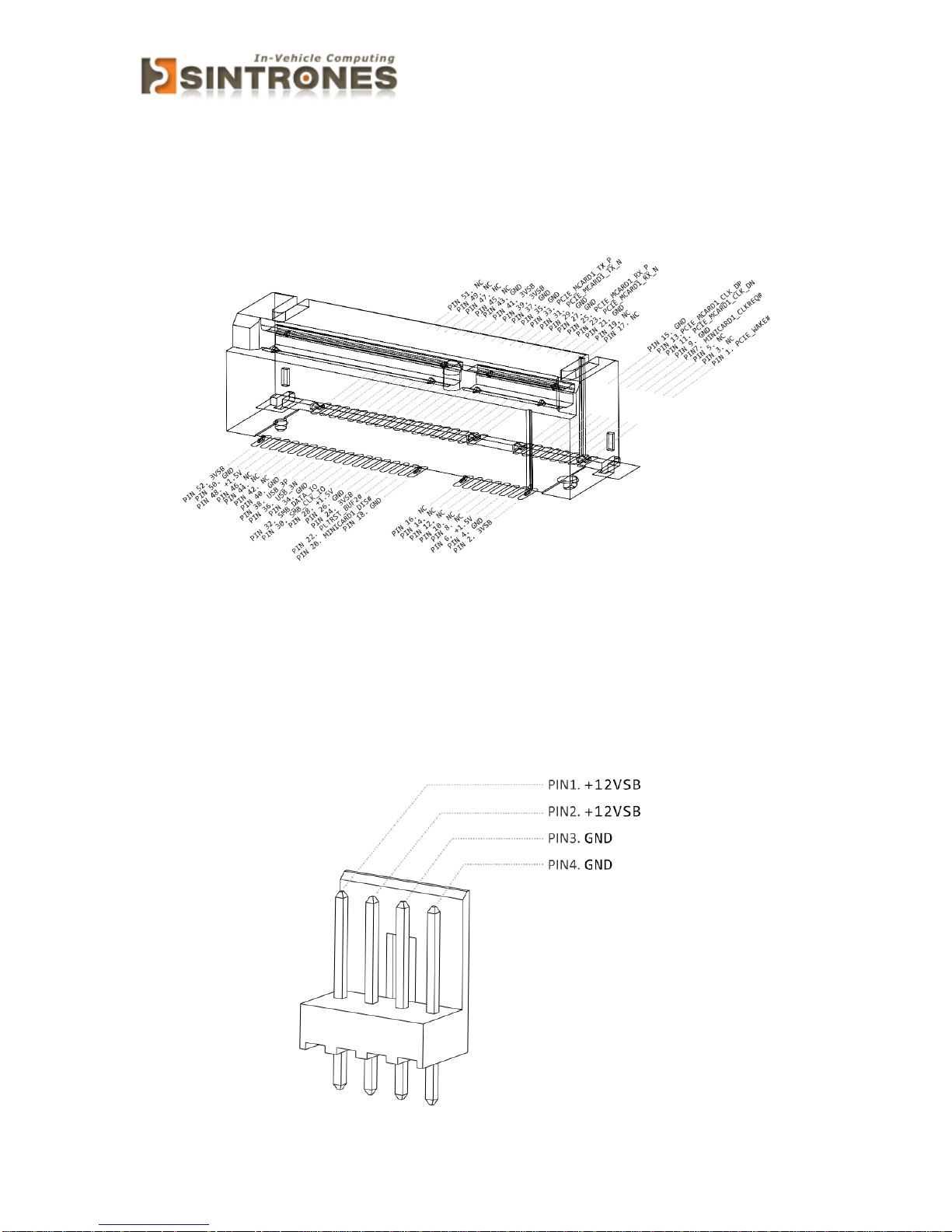
Connector location: MINICARD2
Connector size: 2 X 26 = 52 Pin
Connector type: MINI PCI-E CON 9.2mmH
Power Input Connector
Connector location: SPWR1
Connector size: 1 X 4 = 4 Pin
Connector type: WAFER 2.54mm-M-180
Page 21
SBOX-2320 Manual
20
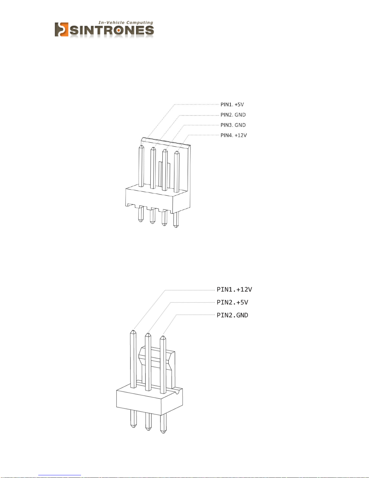
SATA Power Connector
Connector location: SPWR1
Connector size: 1 X 4 = 4 Pin
Connector type: WAFER 2.54mm-M-180
Connector location: SPWR2
Connector size: 1 X 3 = 3 Pin
Connector type: WAFER 2.54mm-M-180
Page 22
SBOX-2320 Manual
21
EXTERNAL CONNECTOR SPECIFICATION
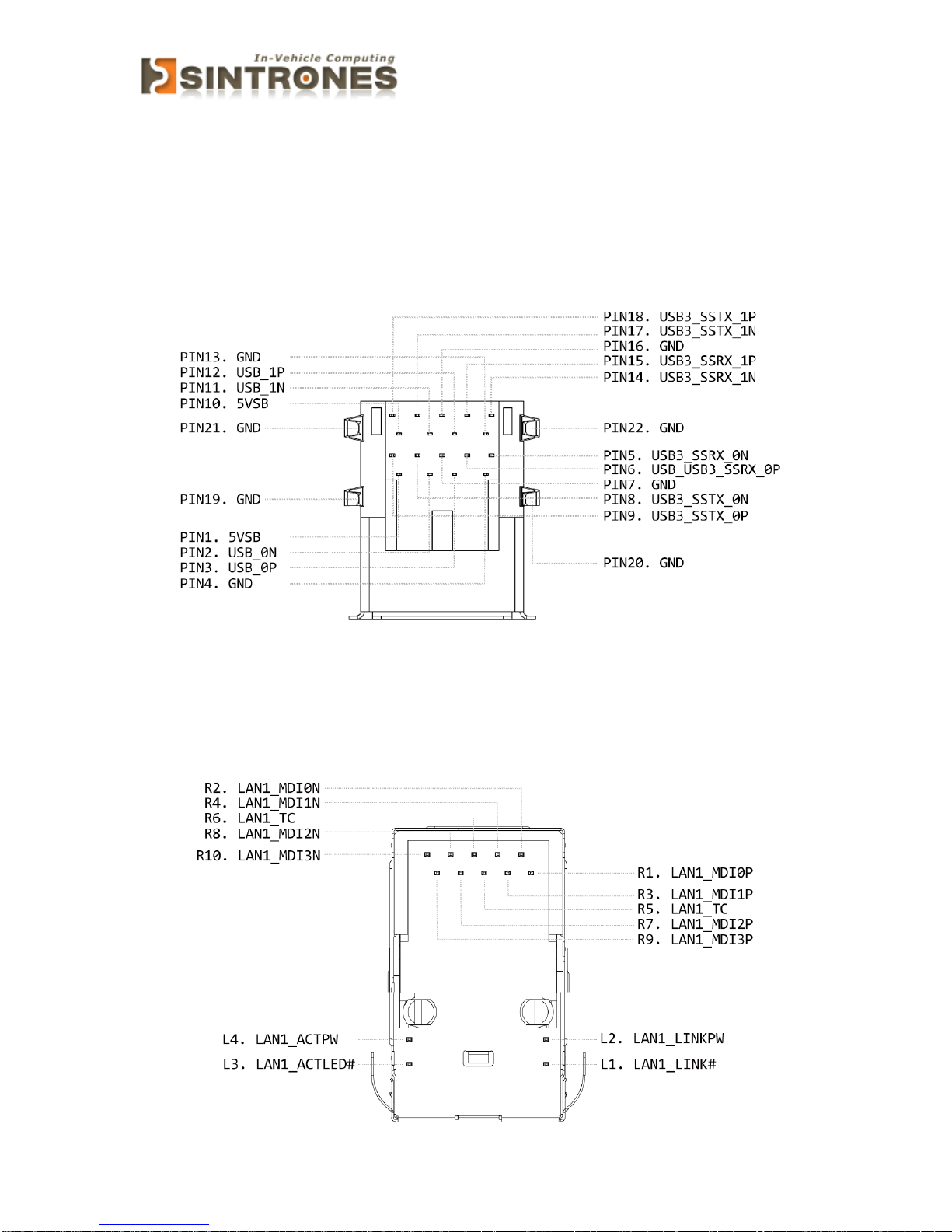
USB Connector
Connector location: USB1
Connector size: 18Pin
Connector type: Type A
LAN connector
Connector location: LAN1
Connector size: 16 Pin
Connector type: RJ45 + LED
Page 23
SBOX-2320 Manual
22
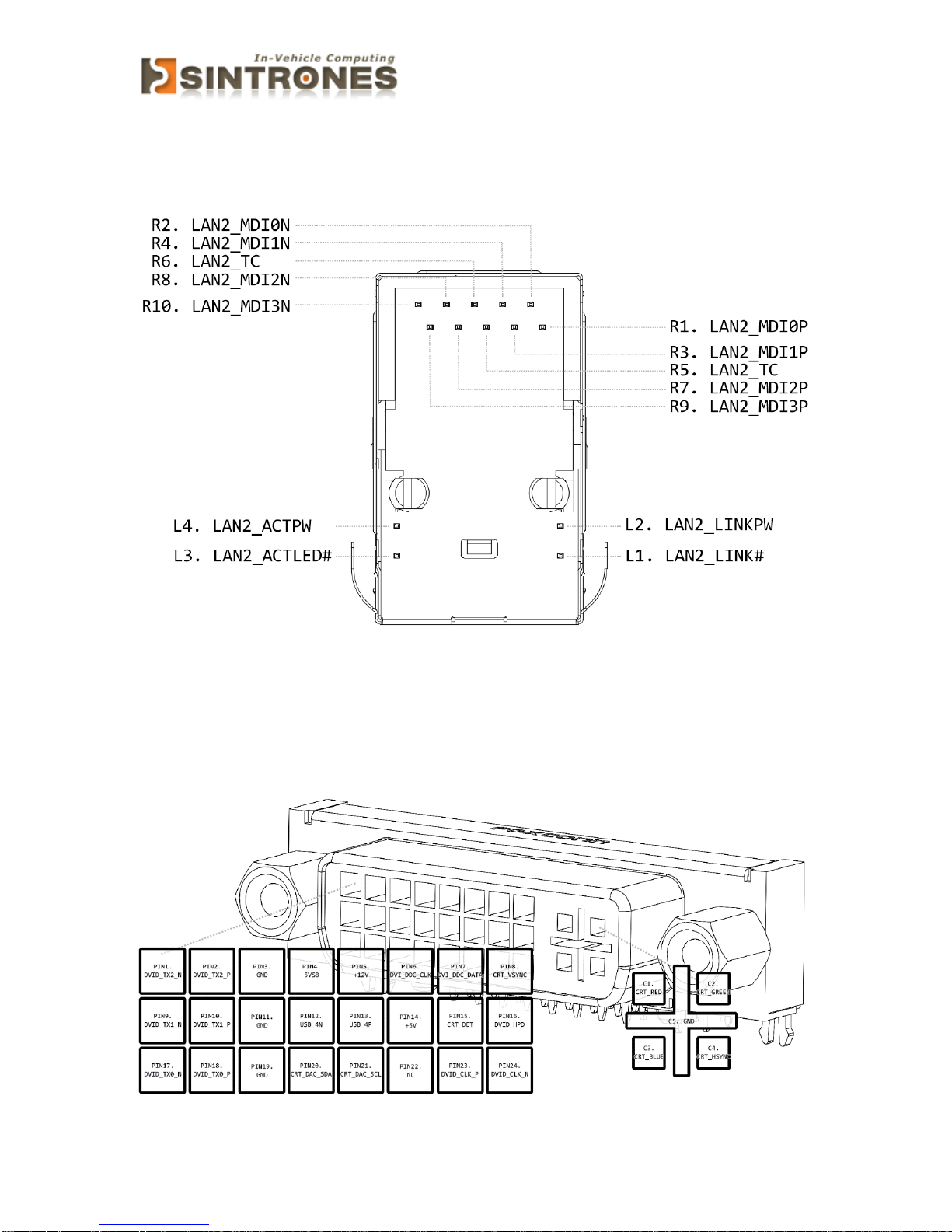
Connector location: LAN2
Connector size: 16 Pin
Connector type: RJ45 + LED
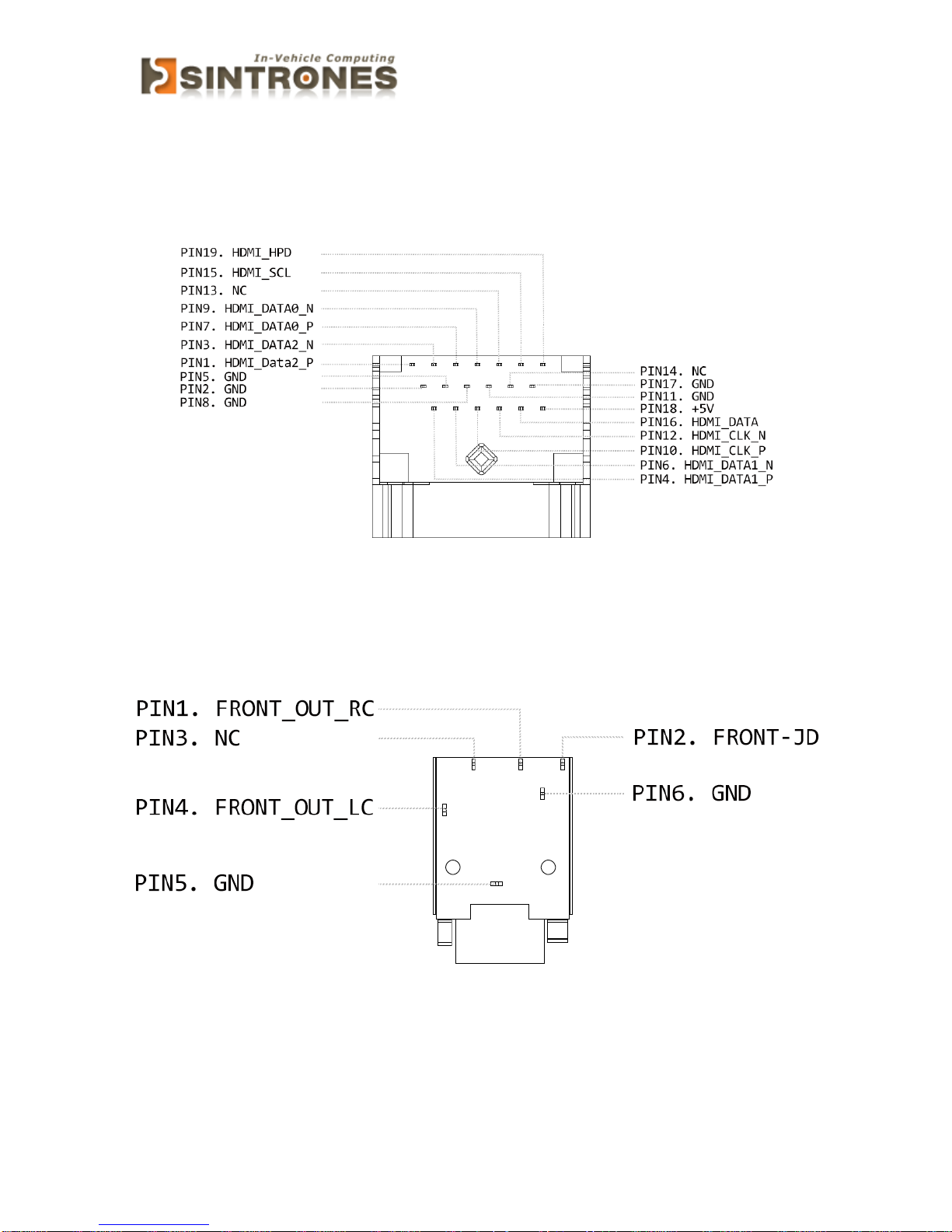
DVI-I connector
Connector location: DVI-I1
Connector size: 30 Pin
Connector type: DVI-I
Page 24
SBOX-2320 Manual
23
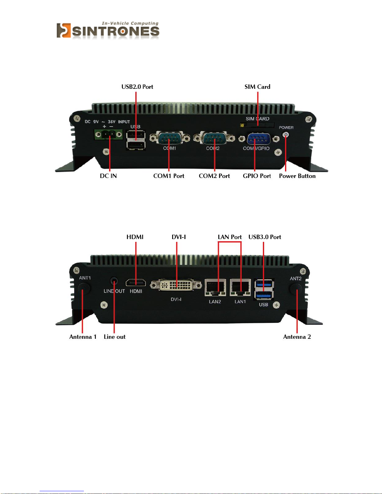
HDMI connector
Connector location: HDMI1
Connector size: 19 Pin
Connector type: HDMI
AUDIO connector
Connector location: LOUT1
Connector size: 6Pin
Connector type: PHONE JACK
Page 25
SBOX-2320 Manual
24
SYSTEM INTRODUCTION
I/O Panel
Page 26
SBOX-2320 Manual
25
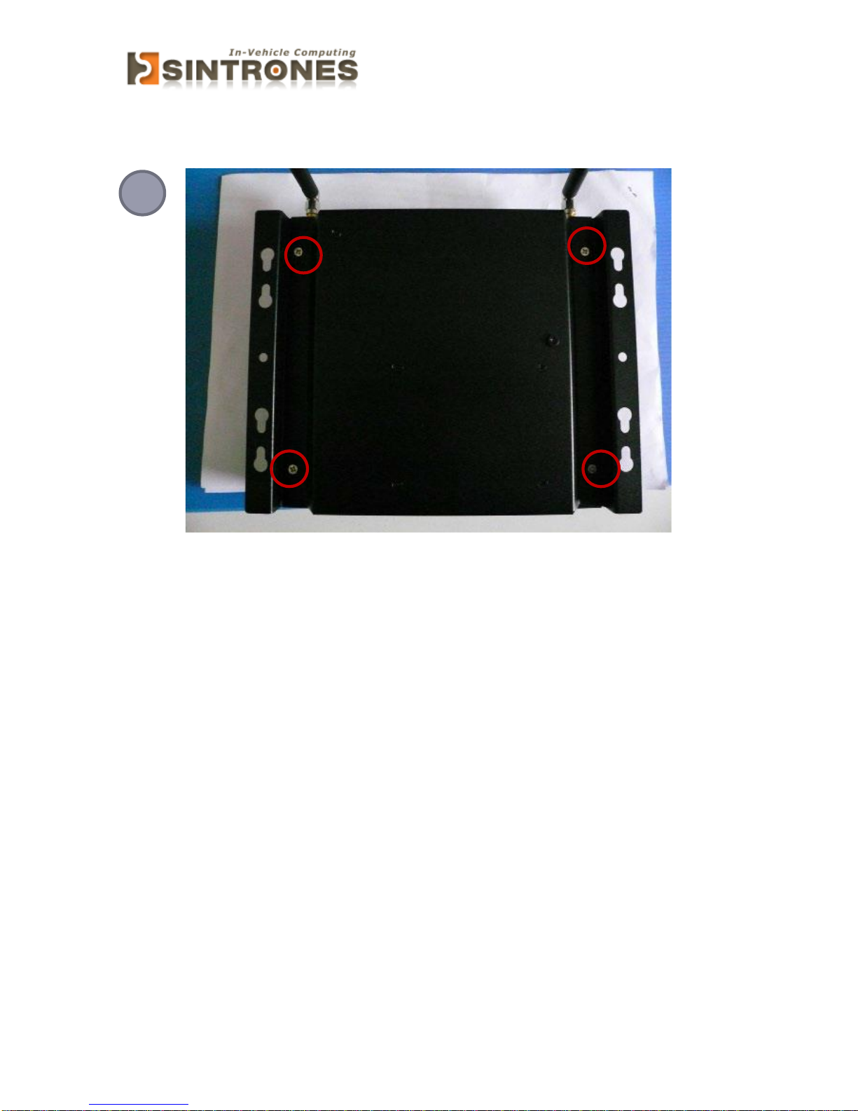
Opening Chassis
Remove the four screws on the Back Cover as figure 1.
1
Page 27
SBOX-2320 Manual
26
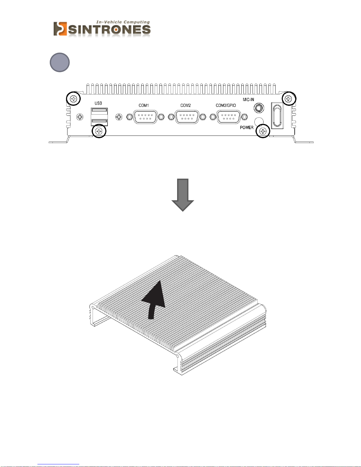
Remove the screws on the Front Panel (four screws) and Rear Panel (four
screws) and open the Top Cover as figure 2.
2
Front Panel/Rear Panel figure
Page 28
SBOX-2320 Manual
27
Installing Memory
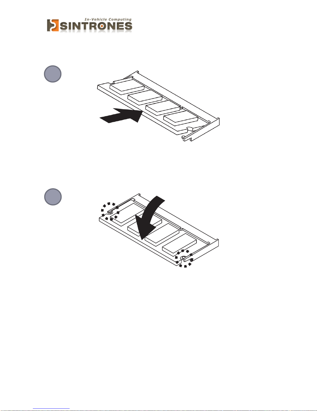
Hold the Memory with its notch aligned with the Memory socket of the board and
insert it at a 30-degree angle into the socket as figure 1.
Press down on the Memory so that the tabs of the socket lock on both sides of the
module as figure 2.
2
1
Page 29
SBOX-2320 Manual
28
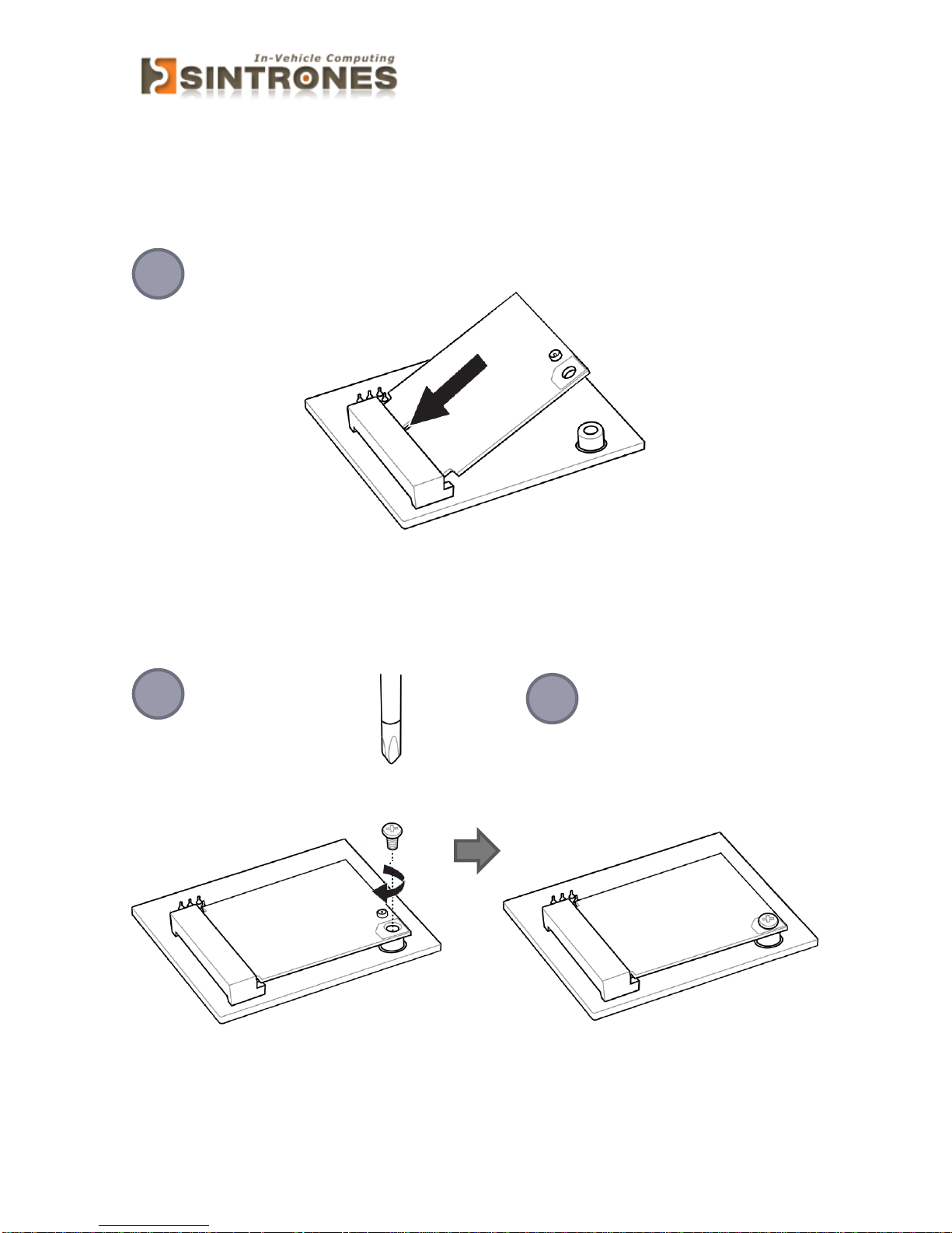
Installing MINI PCIe Expansion Card (MINICARD1)
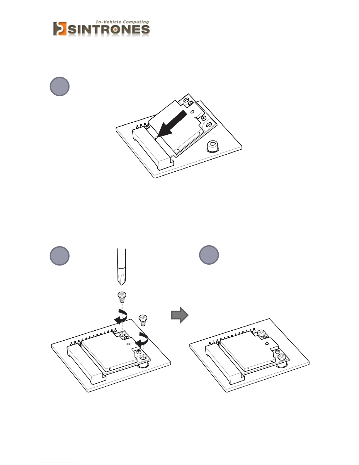
Hold the Module with its notch aligned with the socket of the board and insert it at a
30-degree angle into the socket as shown in the picture.
Secure the card with screw(s) as figure 2 and finish as figure 3.
1 2 3
Page 30
SBOX-2320 Manual
29
Installing MINI PCIe Expansion Card (MINICARD2)
Hold the Module with its notch aligned with the socket of the board and insert it at a
30-degree angle into the socket as shown in the picture.
Secure the card with screw(s) as figure 2 and finish as figure 3.
1 2 3
Page 31
SBOX-2320 Manual
30
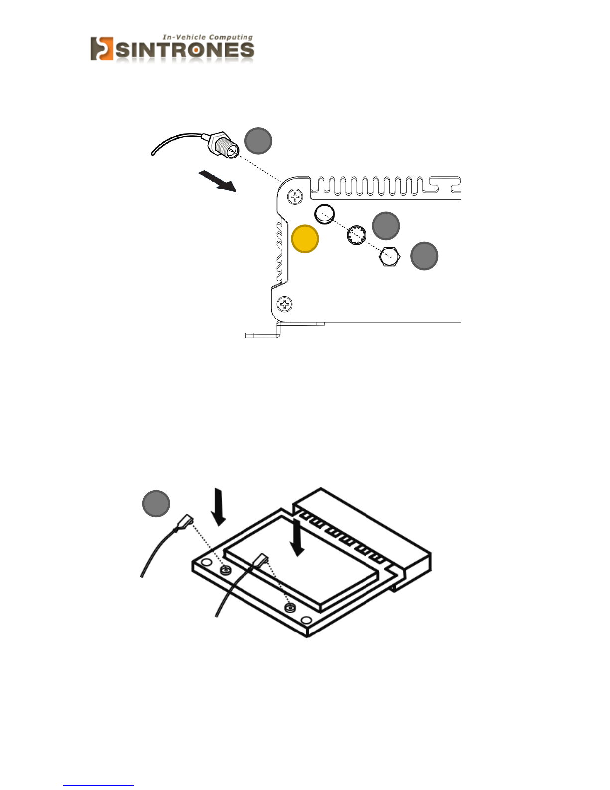
Installing Internal Antenna Cable
Take the SMA Connector (A) and plug into IO Panel (D). Put the Washer(B) into the
SMA Connector (A), then put the O-ring (C) to SMA Connector (A) and tighten as
shown in the picture.
Take the Ipex Connector (A) and press on the Wi-Fi module/3G module/ GPS module
(GPS, only support passive Antenna)
B
C
D
Page 32
SBOX-2320 Manual
31
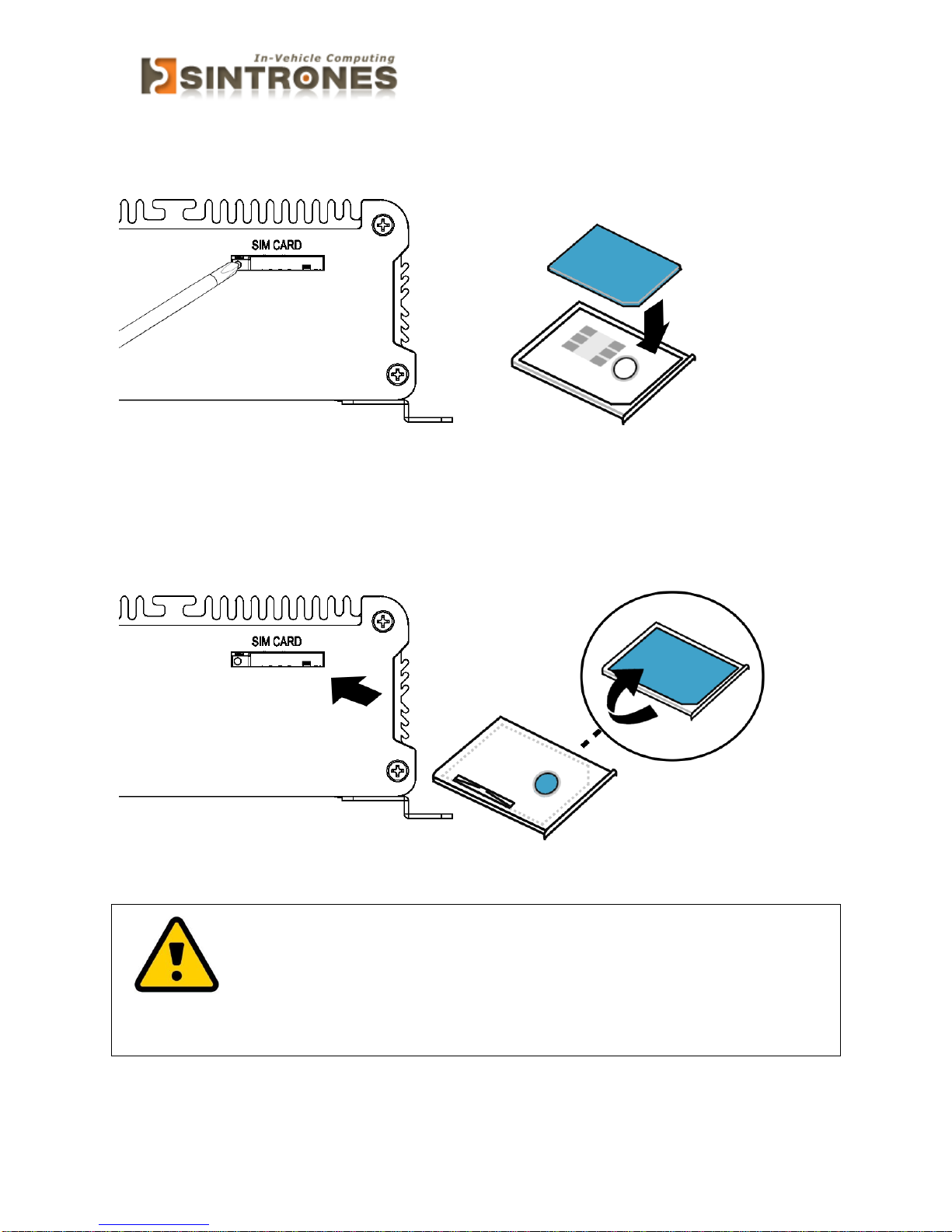
Installing SIM Card
Use thin stick to push the button, then take the holder and put your SIM Card into the
it.
Take the SIM card holder and Insert it into the socket
Attention:
Please cut the main power when you insert the SIM, otherwise the
SIM card will be not detected.
Page 33
SBOX-2320 Manual
32
SYSTEM RESOURCE
GPIO & Delay Time Setting
GPIO and Ignition Control Register
The General Purpose I/O is an interface available on some devices. These can read
digital signals from other parts of a circuit, or output to control other devices. At GPIO
control register, the GPI is use to receive data, the GPO is set data to send.
I/O port: 0xA30 (base address) for Control Register (Read 0xA2h / Write 0xA1h)
0xA31 (base address) for Control Data Value
Debug Command Line
- O A30 A1
- O A31 0F // Set Bit 4-7 to Low
7 6 5 4 3 2 1 0
DO4
DO3
DO2
DO1
DI4
DI3
DI2
DI1
0 = DI is low *
1 = DI is high
0 = DO is low
1 = DO is high *
Page 34
SBOX-2320 Manual
33
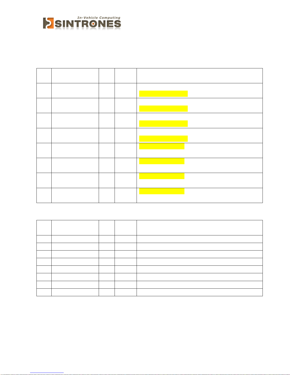
GPIO5 Output Enable Register – Index A0h
Bit
Name
R/W
Defaul
t
Description
7
GPIO57_OE
R/W
0
0 : GPIO57 is input
1 : GPIO57 is output
6
GPIO56_OE
R/W
0
0 : GPIO56 is input
1 : GPIO56 is output
5
GPIO55_OE
R/W
0
0 : GPIO55 is input
1 : GPIO55 is output
4
GPIO54_OE
R/W
0
0 : GPIO54 is input
1 : GPIO54 is output
3
GPIO53_OE
R/W
0
0 : GPIO53 is input
1 : GPIO53 is output
2
GPIO52_OE
R/W
0
0 : GPIO52 is input
1 : GPIO52 is output
1
GPIO51_OE
R/W
0
0 : GPIO51 is input
1 : GPIO51 is output
0
GPIO50_OE
R/W
0
0 : GPIO50 is input
1 : GPIO50 is output
GPIO5 Output Data Register – Index A1h
Bit
Name
R/W
Defaul
t
Description
7
GPIO57_DATA
R/W
1
GPIO57 output data in output mode.
6
GPIO56_DATA
R/W
1
GPIO56 output data in output mode.
5
GPIO55_DATA
R/W
1
GPIO55 output data in output mode.
4
GPIO54_DATA
R/W
1
GPIO54 output data in output mode.
3
GPIO53_DATA
R/W
1
GPIO53 output data in output mode.
2
GPIO52_DATA
R/W
1
GPIO52 output data in output mode.
1
GPIO51_DATA
R/W
1
GPIO51 output data in output mode.
0
GPIO50_DATA
R/W
1
GPIO50 output data in output mode.
Page 35
SBOX-2320 Manual
34
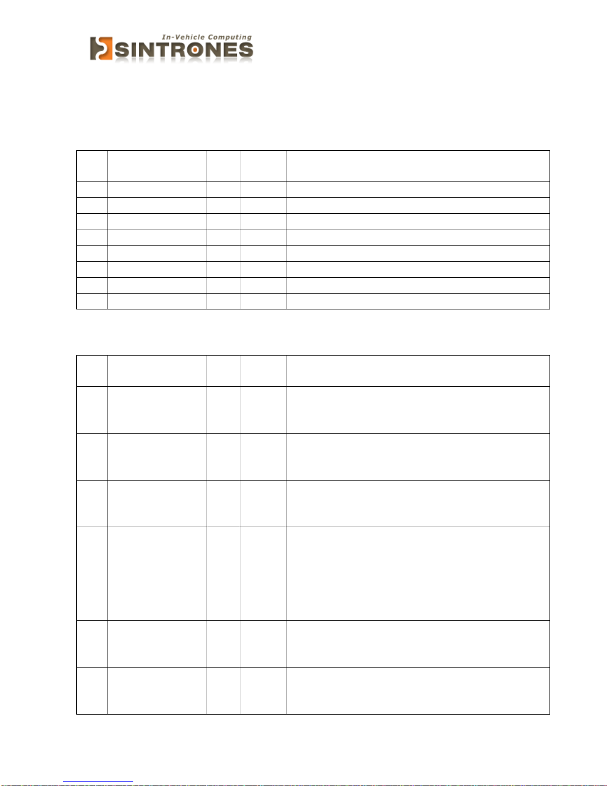
GPIO5 Pin Status Register – Index A2h
Bit
Name
R/W
Defaul
t
Description
7
GPIO57_ST
R 1 GPIO57 pin status.
6
GPIO56_ST
R 1 GPIO56 pin status.
5
GPIO55_ST
R 1 GPIO55 pin status.
4
GPIO54_ST
R 1 GPIO54 pin status.
3
GPIO53_ST
R 1 GPIO53 pin status.
2
GPIO52_ST
R 1 GPIO52 pin status.
1
GPIO51_ST
R 1 GPIO51 pin status.
0
GPIO50_ST
R 1 GPIO50 pin status.
GPIO5 Drive Enable Register – Index A3h
Bit
Name
R/W
Defaul
t
Description
7
GPIO57_DRV_E
NST
R/W
0
GPIO57 Drive Enable
0 : GPIO57 is open drain.
1 : GPIO57 is push pull.
6
GPIO56_DRV_E
NST
R/W
0
GPIO57 Drive Enable
0 : GPIO56 is open drain.
1 : GPIO56 is push pull.
5
GPIO55_DRV_E
NST
R/W
0
GPIO57 Drive Enable
0 : GPIO55 is open drain.
1 : GPIO55 is push pull.
4
GPIO54_DRV_E
NST
R/W
0
GPIO57 Drive Enable
0 : GPIO54 is open drain.
1 : GPIO54 is push pull.
3
GPIO53_DRV_E
NST
R/W
0
GPIO57 Drive Enable
0 : GPIO53 is open drain.
1 : GPIO53 is push pull.
2
GPIO52_DRV_E
NST
R/W
0
GPIO57 Drive Enable
0 : GPIO52 is open drain.
1 : GPIO52 is push pull.
1
GPIO51_DRV_E
NST
R/W
0
GPIO57 Drive Enable
0 : GPIO51 is open drain.
1 : GPIO51 is push pull.
Page 36
SBOX-2320 Manual
35
0
GPIO50_DRV_E
NST
R/W
0
GPIO57 Drive Enable
0 : GPIO50 is open drain.
1 : GPIO50 is push pull.
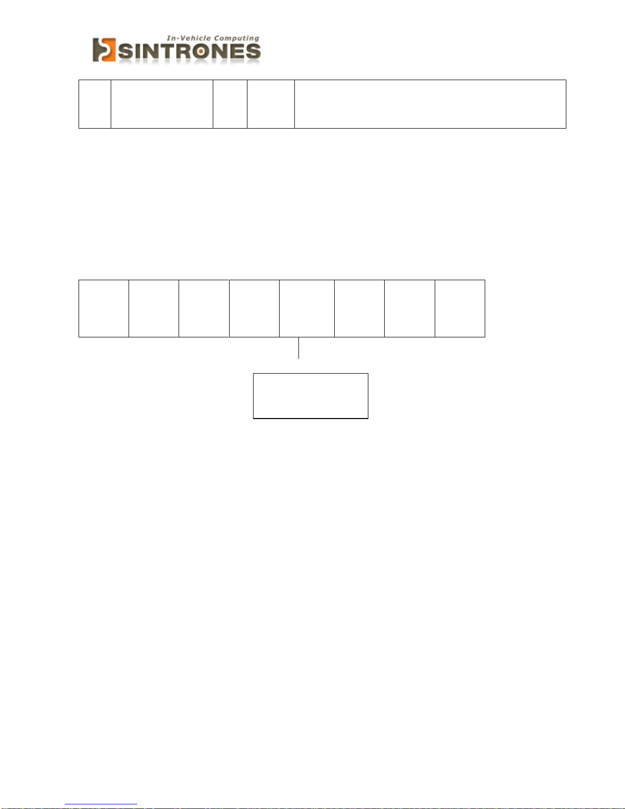
I/O port: I/O port: 0xA30 (base address) for Control Register (Read 0xF2h
bit 3)
0xA31 (base address) for Control Data Value
7 6 5 4 3 2 1 0
X X X
X
Ignition
Status
X
X
X
Debug Command Line
- O A30 F2
- I A31 // Check Bit 3 Status
0 = Ignition off
1 = Ignition on
Page 37

SBOX-2320 Manual
36
BIOS
Enter The BIOS
Power on the computer and the system will start POST (Power On Self Test)
process. When the message below appears on the screen, press (DEL) key to
enter Setup.
Press DEL to enter SETUP
If the message disappears before you respond and you still wish to enter Setup,
restart the system by turning it OFF and On or pressing the RESET button. You
may also restart the system by simultaneously pressing <Ctrl>, <Alt>, and
<Delete> keys.
Important
The items under each BIOS category described in this chapter are under
continuous update for better system performance. Therefore, the
description may be slightly different from the latest BIOS and should be held
for reference only.
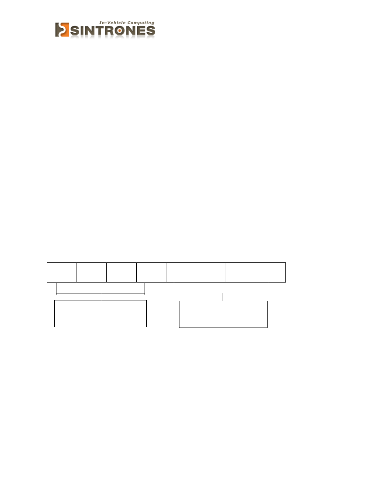
Upon boot-up, the 1st line appearing after the memory count is the BIOS
version. It is usually in the format.
SBOX-2620 Mainboard V1.0 073109 where :
1st digit refers to BIOS maker as A = AMI, W = AWARD, and P = PHOENIX
2nd - 5th digit refers to the model number.
6th digit refers to the chipset as I = Intel, N = NVIDIA, A = AMD and V = VIA.
7th - 8th digit refers to the customer as MS = all standard customers.
V1.0 refers to the BIOS was released.
073109 refers to the date this BIOS was released.
Page 38

SBOX-2320 Manual
37
Control Keys
Power on the computer and the system will start POST (Power On Self Test)
process. When the message below appears on the screen, press (DEL) key to
enter Setup.
<↑>
Move to the previous item
<↓>
Move to the next item
<←>
Move to the item in the left hand
<→>
Move to the item in the right hand
<Enter>
Select the item
<Esc>
Jumps to the Exit menu or returns to the main menu from a
submenu
<+/PU>
Increase the numeric value or make changes
<-/PD>
Decrease the numeric value or make changes
<F1>
General Help
<F3>
Load Optimized Defaults
<F4>
Save all the CMOS changes and exit
Getting Help
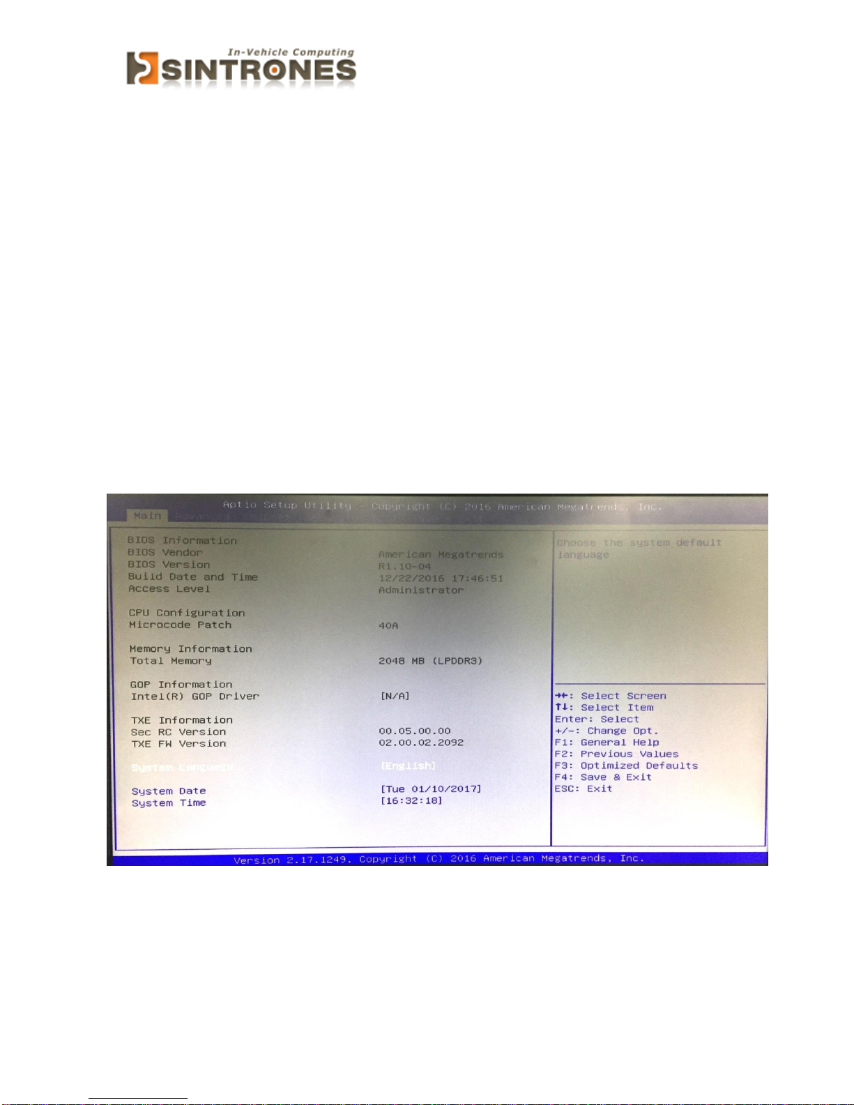
After entering the Setup menu, the first menu you will see is the Main Menu.
Main Menu
The main menu lists the setup functions you can make changes to. You can use
the arrow keys (↑↓) to select the item. The on-line description of the highlighted
setup function is displayed at the bottom of the screen.
Sub-Menu
Page 39
SBOX-2320 Manual
38
If you find a right pointer symbol (as shown in the right view) appears to the left
of certain fields that means a sub-menu can be launched from this field. A submenu contains additional options for a field parameter. You can use arrow keys
( ↑↓ ) to highlight the field and press <Enter> to call up the sub-menu. Then you
can use the control keys to enter values and move from field to field within a
sub-menu. If you want to return to the main menu, just press the <Esc >.
General Help <F1>
The BIOS setup program provides a General Help screen. You can call up this
screen from any menu by simply pressing <F1>. The Help screen lists the
appropriate keys to use and the possible selections for the highlighted item.
Press <Esc> to exit the Help screen.
Main
» System Date
This setting allows you to set the system Date. The time format is <Day>
<Month> <Date> <Year>.
» System Time
Page 40
SBOX-2320 Manual
39
This setting allows you to set the system time. The time format is <Hour>
<Minute> <Second>.
Advanced
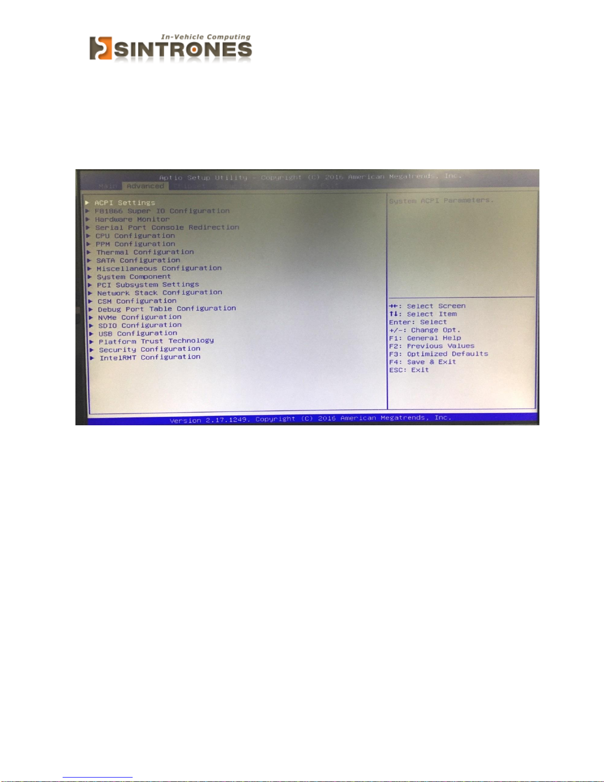
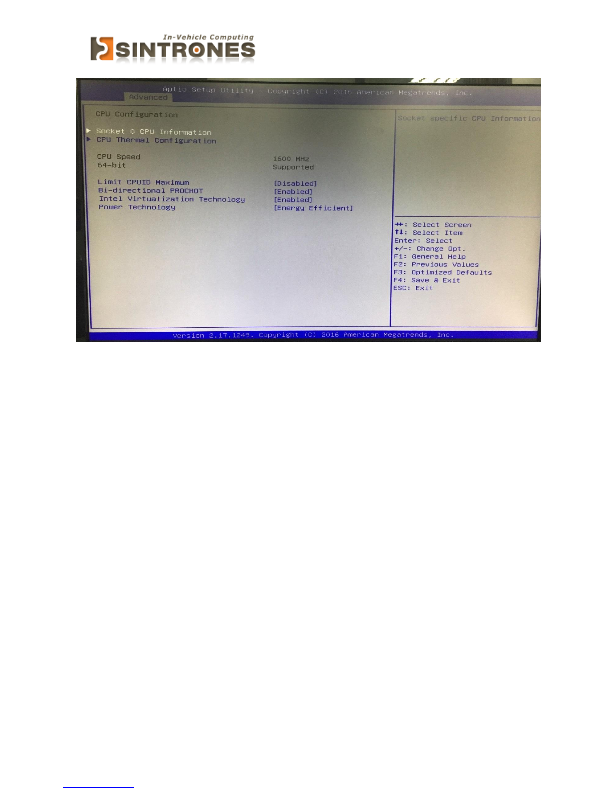
CPU Configuration
Page 41
SBOX-2320 Manual
40
» Limit CPUID Maximum
The CPUID instruction of some newer CPUs will return a value greater than
3. The default is Disabled because this problem does not exist in the
Windows series operating systems. If you are using an operating system
other than Windows, this problem may occur. To avoid this problem, enable
this field to limit the return value to 3 or less than 3.
» Intel Virtualization Technology
When this field is set to Enabled, the VMM can utilize the additional
hardware capabilities provided by Vanderpool Technology.
» EIST
This field is used to enable or disable the Intel Enhanced SpeedStep
Technology
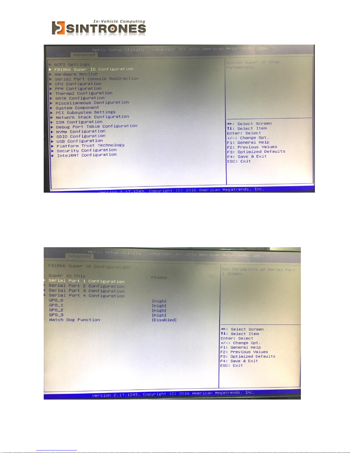
Super IO Configuration
Page 42
SBOX-2320 Manual
41
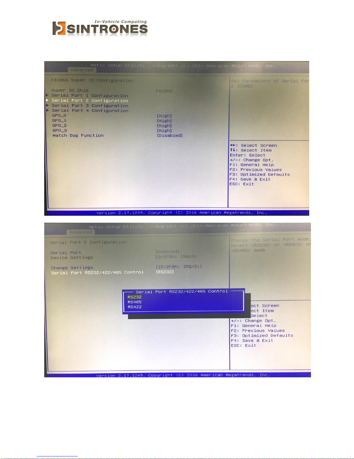
» Serial Port 0/1/2/3 Enable or Disable
Select an Enable or Disable for the specified serial ports.
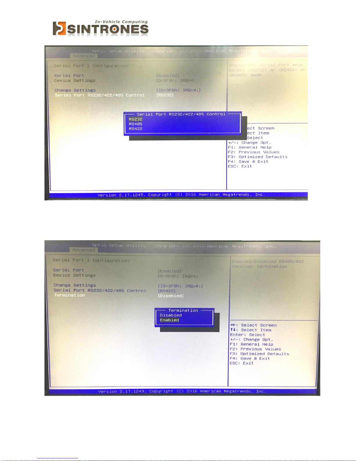
» COM1 RS232/422/485 Select
Page 43
SBOX-2320 Manual
42
RS422 need to choice Termination and slect Enabled
Page 44
SBOX-2320 Manual
43
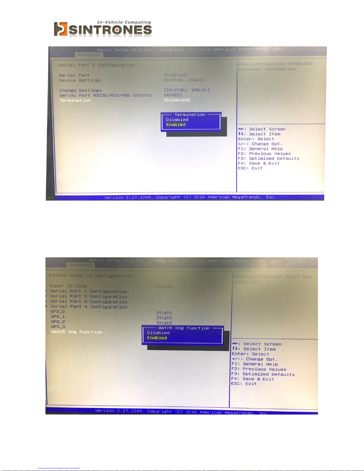
» COM2 RS232/422/485 Select
RS422 nee to choice Termination and select Enabled
Page 45
SBOX-2320 Manual
44
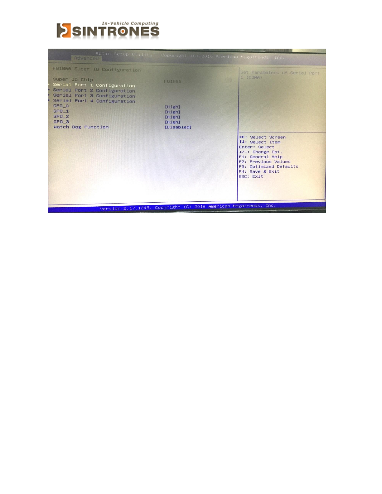
» Watch Dog Function
» GPIO Configuration
Page 46
SBOX-2320 Manual
45
» GPO 0/ 1/ 2/ 3/ Data
These settings configure special GPIO data.
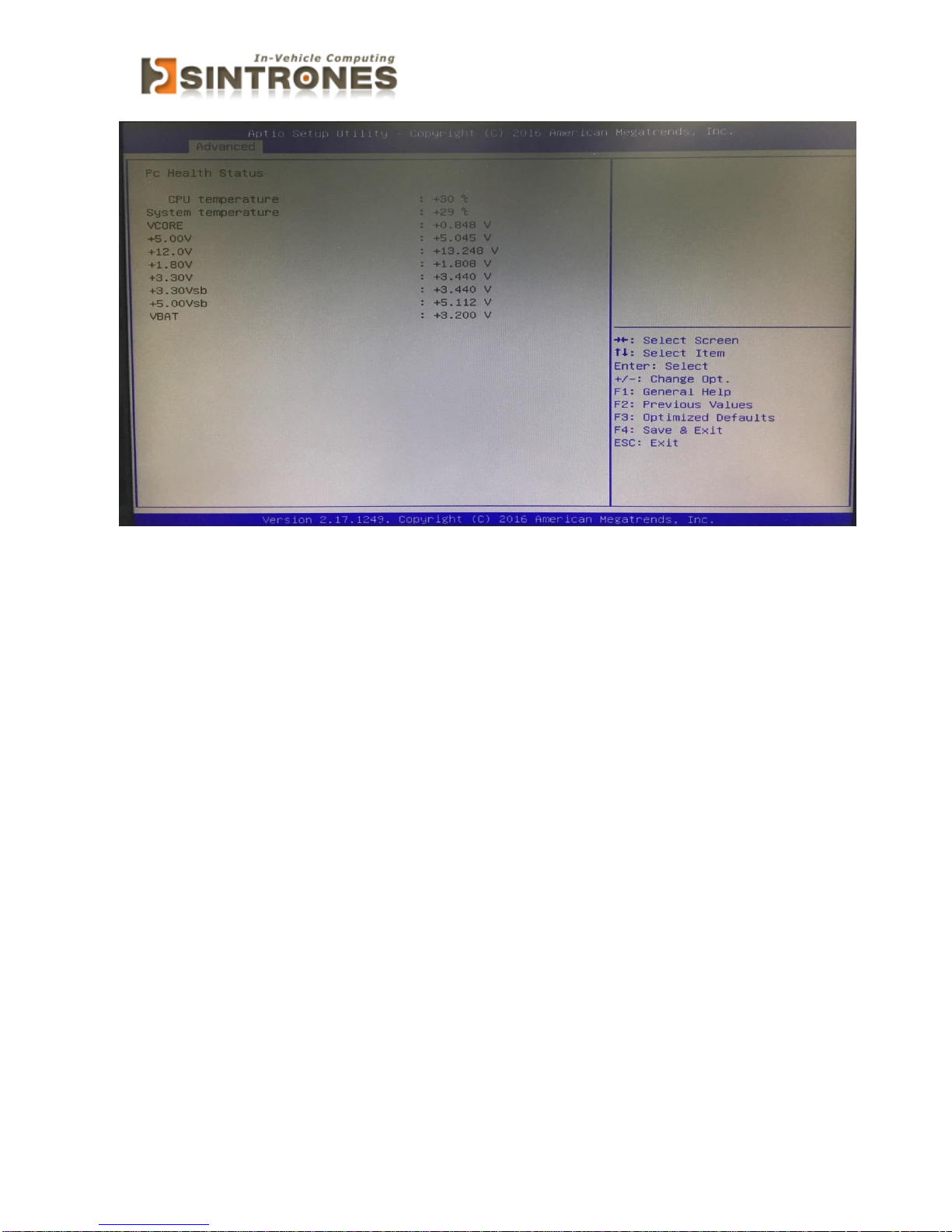
Hardware Health Configuration
These items display the current status of all monitored hardware
devices/components such as voltages, temperatures and all fans' speeds.
Page 47
SBOX-2320 Manual
46
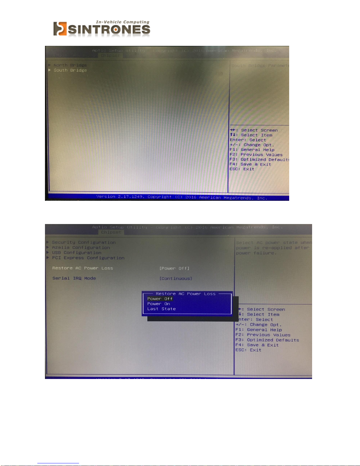
Chipset
PCH-IO Configuration
Page 48
SBOX-2320 Manual
47
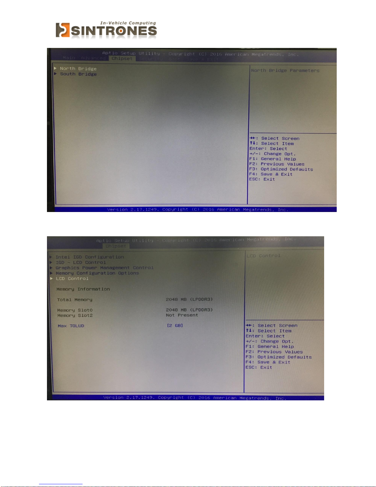
System Agent (SA) Configuration
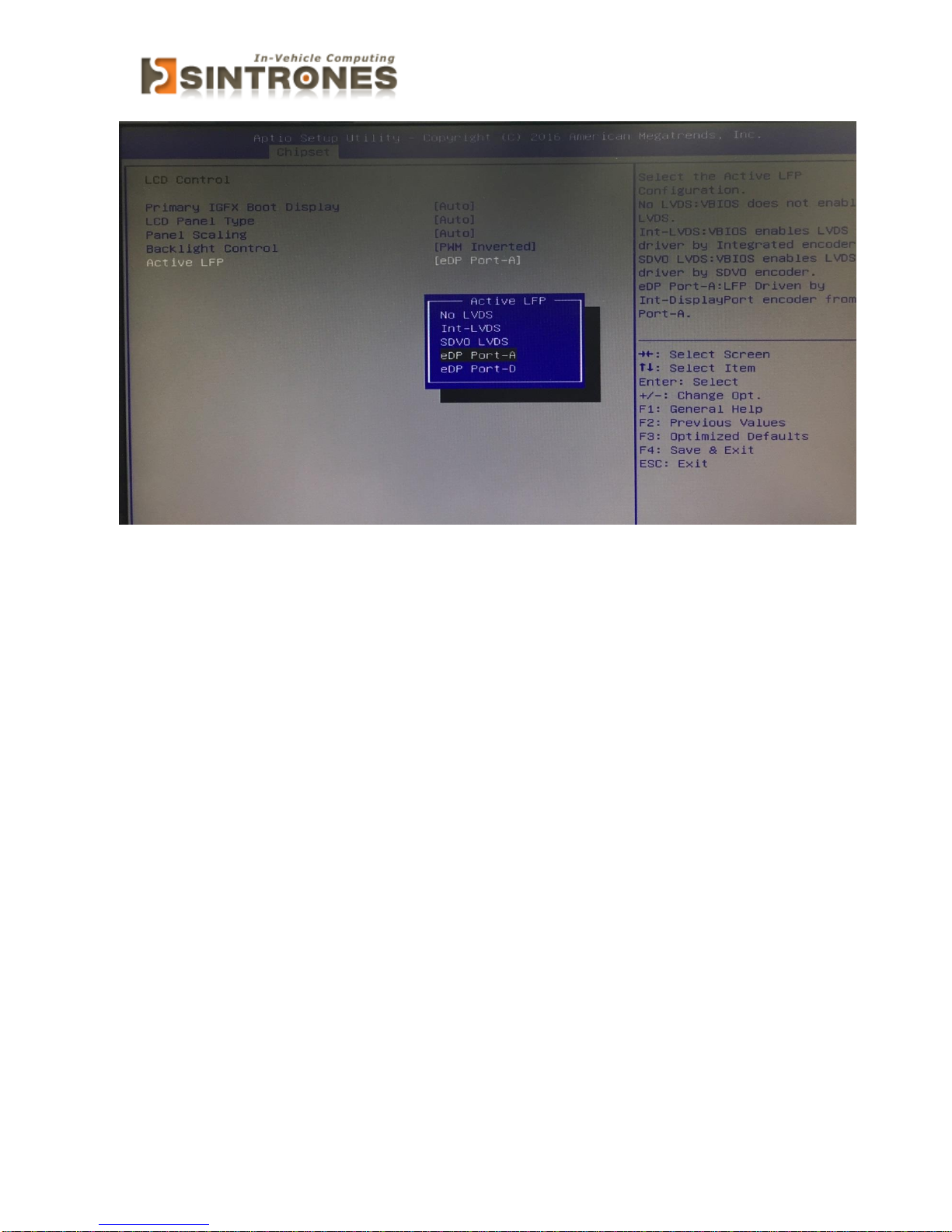
» Graphics Configuration
Page 49
SBOX-2320 Manual
48
Page 50
SBOX-2320 Manual
49
Page 51
SBOX-2320 Manual
50
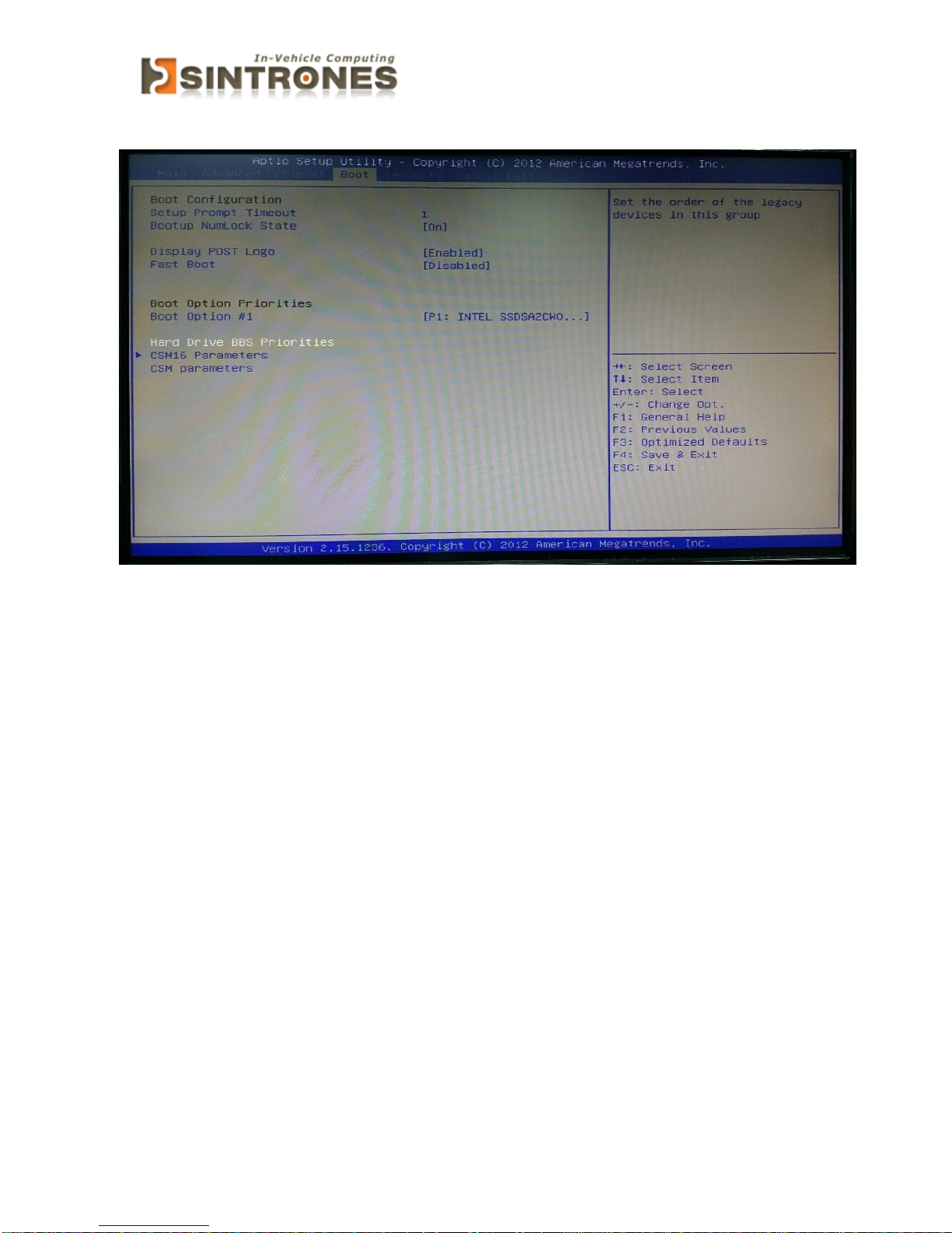
Boot
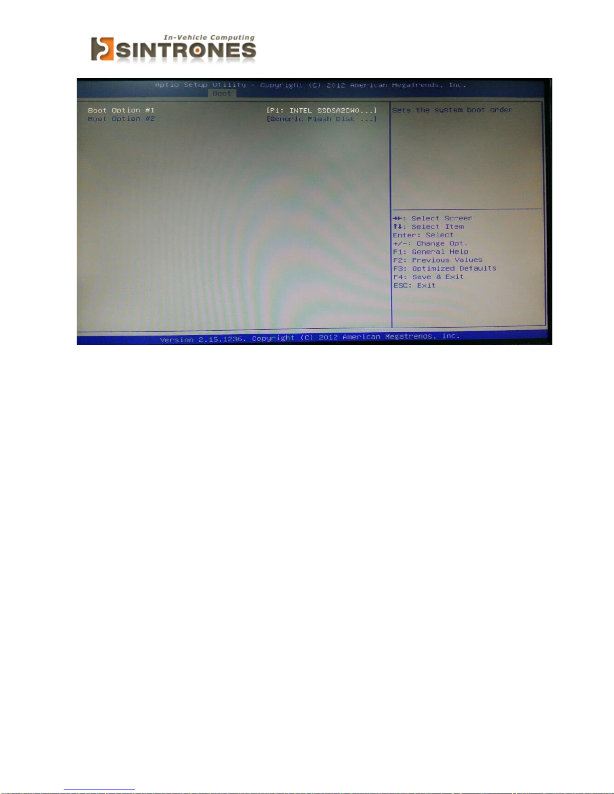
» 1st/2nd/3rd Boot Device
The items allow you to set the sequence of boot devices where BIOS
attempts to load the disk operating system.
» Try Other Boot Devices
Setting the option to [Enabled] allows the system to try to boot from other
device if the system fail to boot from the 1st/2nd/3rd boot device.
Page 52
SBOX-2320 Manual
51
» Hard Disk Drives, CD/DVD Drives, USB Drives
These settings allow you to set the boot sequence of the specified devices.
Page 53
SBOX-2320 Manual
52
Security
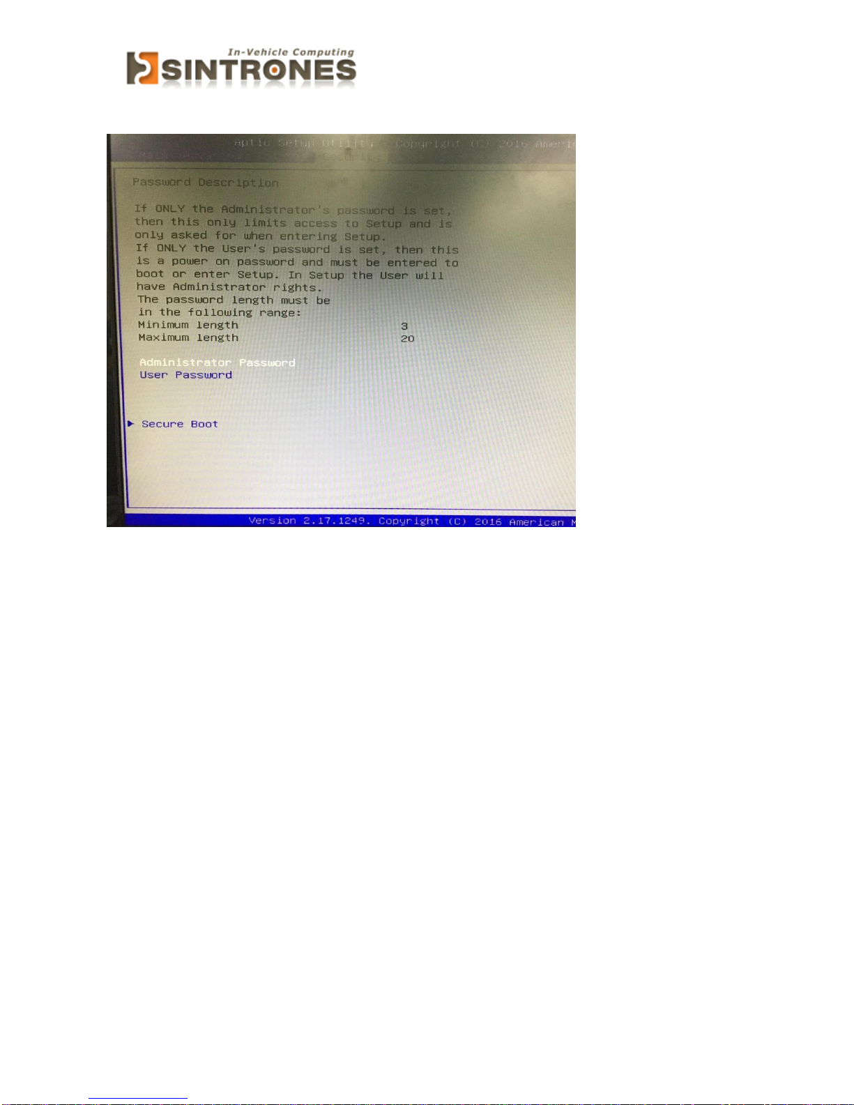
» Administrator Password
Administrator Password controls access to the BIOS Setup utility. These
settings allow you to set or change the administrator password.
» User Password
User Password controls access to the system at boot. These settings allow
you to set or change the user password.
» Boot Sector Virus Protection
This function protects the BIOS from accidental corruption by unauthorized
users or computer viruses. When enabled, the BIOS data cannot be changed
when attempting to update the BIOS with a Flash utility. To successfully
update the BIOS, you will need to disable this Flash Protection function.
Page 54
SBOX-2320 Manual
53
Exit
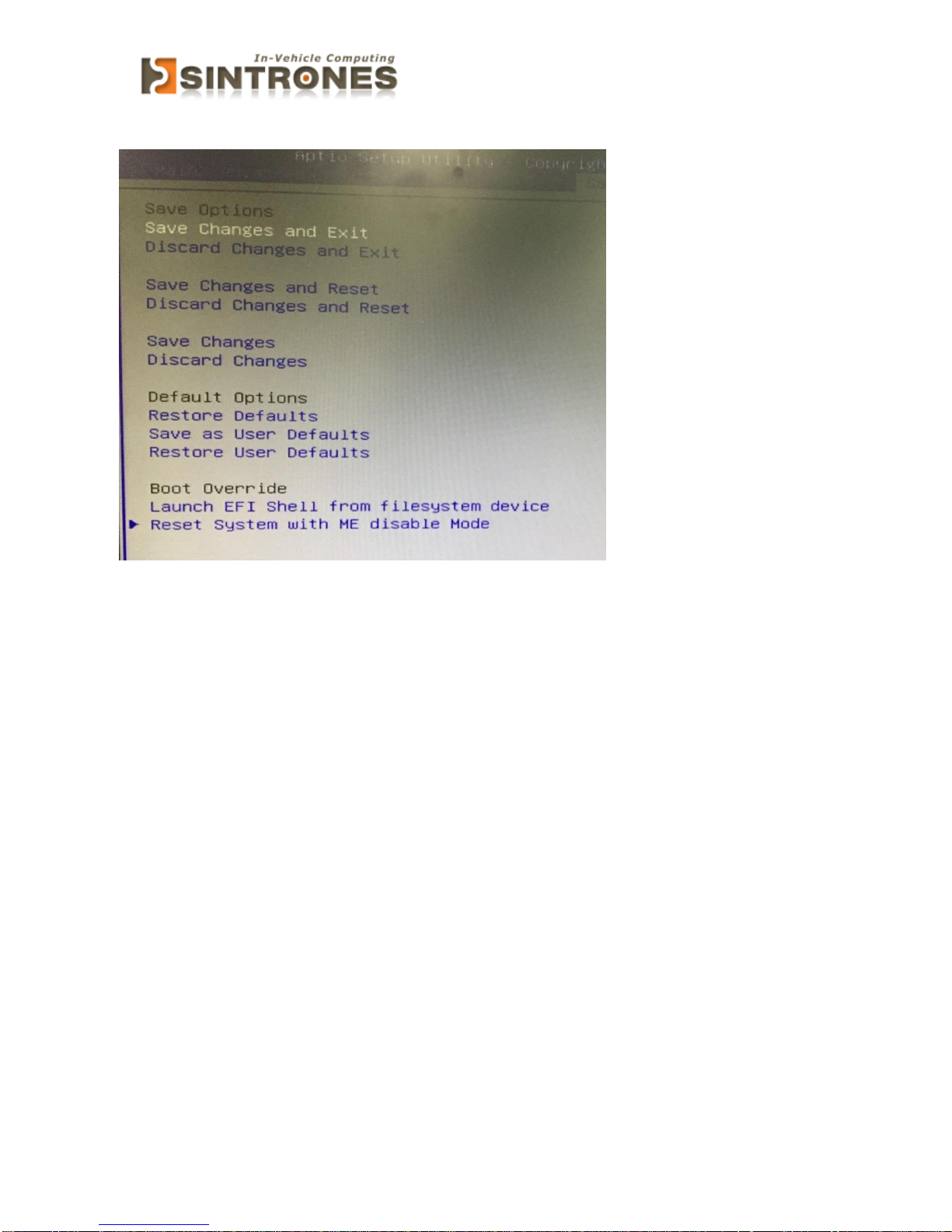
» Save Changes and Exit
Save changes to CMOS and exit the Setup Utility.
» Discard Changes and Exit
Abandon all changes and exit the Setup Utility.
» Discard Changes
Abandon all changes and continue with the Setup Utility.
» Load Optimal Defaults
Use this menu to load the default values set by the mainboard manufacturer
specifically for optimal performance of the mainboard.
» Load Failsafe Defaults
Use this menu to load the default values set by the BIOS vendor for stable
system performance.
Page 55
SBOX-2320 Manual
54
PACKING LIST
System
Item
Part Number
Module Name
1
762320011000
SBOX-2320-N0 Barebone
2
762320011001
SBOX-2320-N1 Barebone
3
762320011002
SBOX-2320-N2 Barebone
4
762320011003
SBOX-2320-4S-N0
Accessory
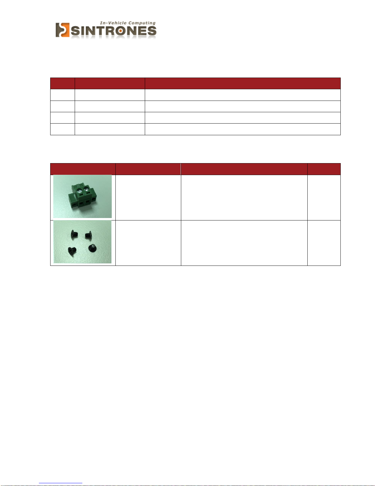
Picture
Part Number
Module Name
Q’ty
326910029661
CABLING MC101-508-02GA1 F
90D
1 351103040250
Screw F Type M3*4L ISO BK
4
 Loading...