

Page 1
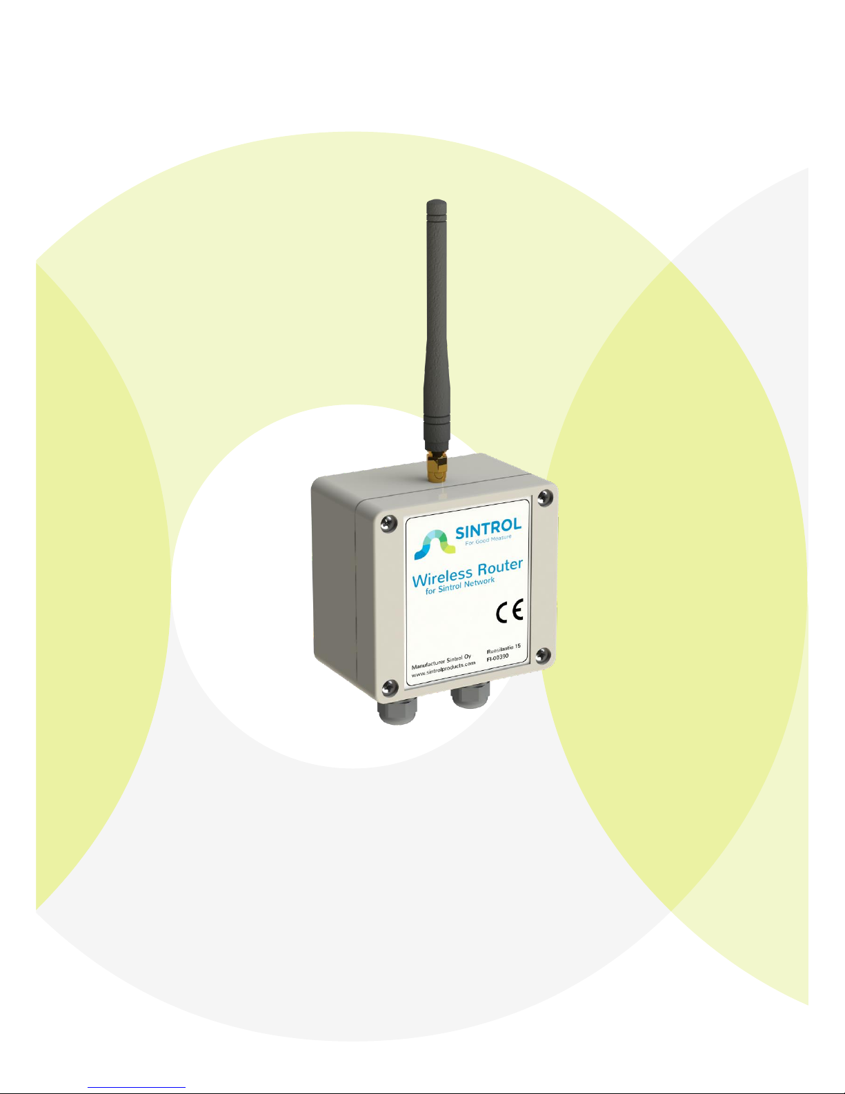
Sintrol Wireless Router
Manual
Version 1.0.1
Page 2

Wireless Router User Manual 2
Table of Contents
1 INTRODUCTION ......................................................................................... 3
1.1 Product overview ........................................................................................... 3
2 INSTALLATION ........................................................................................... 4
2.1 Selecting the installation location .................................................................. 4
3 WIRING ..................................................................................................... 6
3.1 Building Sintrol network ................................................................................ 7
Applying local RF bus ................................................................................ 7
4 DIMENSIONS ............................................................................................. 9
5 OPERATION .............................................................................................. 10
5.1 PARAMETERS ............................................................................................... 10
5.2 PROPERTIES .................................................................................................. 11
RS485 ...................................................................................................... 11
USB ......................................................................................................... 11
RF ............................................................................................................ 11
Security key ............................................................................................ 11
Lock password ........................................................................................ 11
Device password .................................................................................... 11
5.3 NETWORK ..................................................................................................... 13
Create the network ................................................................................ 13
Manually routing the devices ................................................................. 13
Transmission power level options ......................................................... 14
Usage of transmission power levels ....................................................... 14
6 MAINTENANCE ......................................................................................... 15
7 TROUBLESHOOTING .................................................................................. 15
7.1 No USB-connection to PC ............................................................................. 15
7.2 No response over RF .................................................................................... 15
7.3 No response over RS485 .............................................................................. 15
Page 3

Wireless Router User Manual 3
1 INTRODUCTION
This manual describes how to install and use SINTROL’s Wireless Router product.
Sintrol shall not be liable for any loss or damage whatsoever arising from use of
any information or details therein, or omission or error in this manual, or any
misuse of the product.
The instrument can be accessed by utilizing the free DustTool software to manage
the basic settings of the product.
Commercial software product DustLog provides comprehensive control and
diagnostics tools over the product and over the whole Sintrol network.
Features of the Wireless Router are for example:
Gather data from Sintrol Network seamlessly, utilizing RS485 and RF
connections between products.
Visualize the Sintrol network topology and unit locations.
Provide tools to:
o Automatically form the network
o Manually modify the network
o Get real time diagnostics
Manage and parameterize all products within the Sintrol Network
The DustTool software can be downloaded free of charge from Sintrol web-site
http://www.sintrolproducts.com
1.1 Product overview
The Wireless Router Dust monitor is a microprocessor-based unit, equipped with
USB, RS485 and Sintrol’s local RF-link connections.
The device is designed to manage all Sintrol products connected to Sintrol
Network. The Wireless Router has been specifically designed for easy installation
and reliable operation.
Page 4

Wireless Router User Manual 4
2 INSTALLATION
2.1 Selecting the installation location
The best location for installation location is where RF antenna is not blocked by
large metal objects or walls, which may cause reflections or block the wireless
signal.
Although the device is IP65 classified and can handle industrial conditions, avoiding
unnecessary environmental stress is encouraged.
If possible, during the installation ensure that:
1. Temperature conditions are mild and temperature variation is not extreme.
2. Unit is not installed into direct sun light
3. No large amplitude vibration exists
4. The unit is not directly exposed to any kind of piling particles, especially
conductive.
5. The unit is not directly exposed to soil dust, dirt, snow or rain.
6. The unit is to be installed the way that the antenna points upwards.
7. The unit is not installed next to third party devices applying RF-
communication or creating strong RF disturbances.
Enclosure supports optional mounting feet installation, to enable easy wall
installations.
Page 5

Wireless Router User Manual 5
Figure 1 Installation with optional mounting feet.
Page 6
Wireless Router User Manual 6
3 WIRING
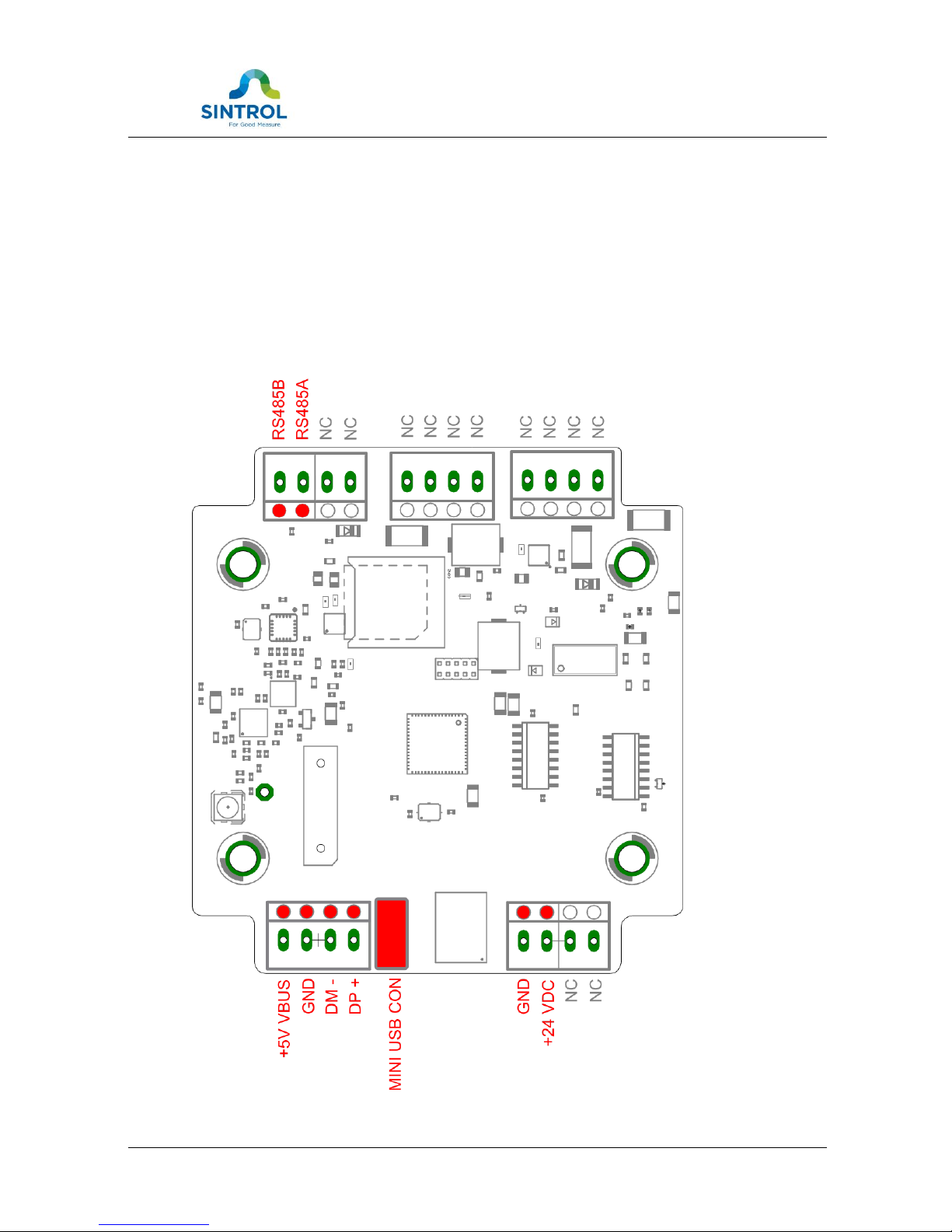
To connect the device, open the enclosure. Any unnecessary exposure of the
connectors to moisture or dirt needs to be avoided.
NC = Not connected.
Table 1 Wiring and signals
Page 7
Wireless Router User Manual 7
3.1 Building Sintrol network
Applying local RF bus
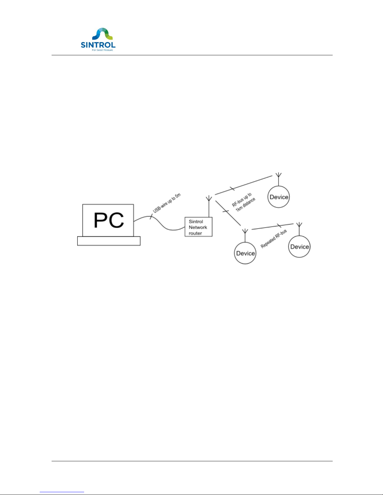
Local area radio frequency bus operates within international license free ISMbands. All Sintrol products equipped with RF-link operate as a part of the bus,
creating and routing data within the network. This feature in most cases eliminate
any need for repeaters or manual configuration tasks.
RF-bus is especially recommended to be used in industrial locations where bidirectional communication is required and/or a strong galvanic isolation is needed.
Long distance connections up to 1 km without the line of sight can be acquired.
Range can also be extended with accessories like directional antennas and/or
separate repeater units.
Figure 2 RF bus application example
Notes:
Sintrol Network Router operates with Sintrol products having RF-network support.
Page 8

Wireless Router User Manual 8
TECHNICAL SPECIFICATION
Product name
Wireless Router
Protection Category
IP65
Power Supply
12 - 24 VDC
Power Consumption
Under 3W, depending on usage
Wiring
Two DIN PG11 glands for cables
Connectors
1. USB wires connectore with 45° angle:
a. solid from 0.2 to 1.5 mm
2
b. stranded from 0.2 to 1.0 mm
2
2. Low voltage conn with 45° angle:
a. solid from 0.2 to 1.5 mm
2
b. stranded from 0.2 to 1.0 mm
2
3. mini USB connector inside the box
Communication Interfaces
Serial communication: RS-485
USB
Radio frequency (RF)
Communication Protocol
Proprietary Sintrol Network protocol
Wireless communication
Transmit power
Up to 400 mW (+26 dBm), user adjustable
Frequency band
868/915 MHz (license free ISM band)
15 channels
Receiver sensitivity
-110 dBm
Typical range (no line of sight)
Up to 1300 m in urban environment
Up to 11 km with directional antennas
Materials and Weight
Enclosure
Plastic ABS
Weight, excluding antenna
180 g
Weight of standard antenna
20 g
Table 2 Technical specification
Page 9
Wireless Router User Manual 9
4 DIMENSIONS
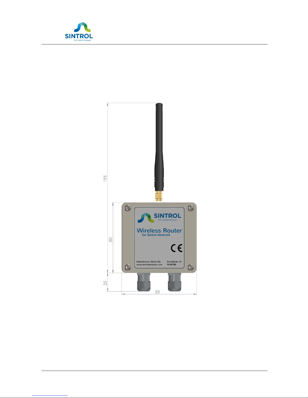
Figure 3 Structure and dimensions
Page 10
Wireless Router User Manual 10
5 OPERATION
The Wireless Router creates and maintains the connections between Sintrol
Products and Sintrol’s PC software, thus the main operation of the Wireless Router
is mostly transparent.
Device itself has but a few configuration related controls of its own. All the controls
are managed by the dedicated Sintrol PC-softwares: DustTool and/or DustLog.
5.1 PARAMETERS
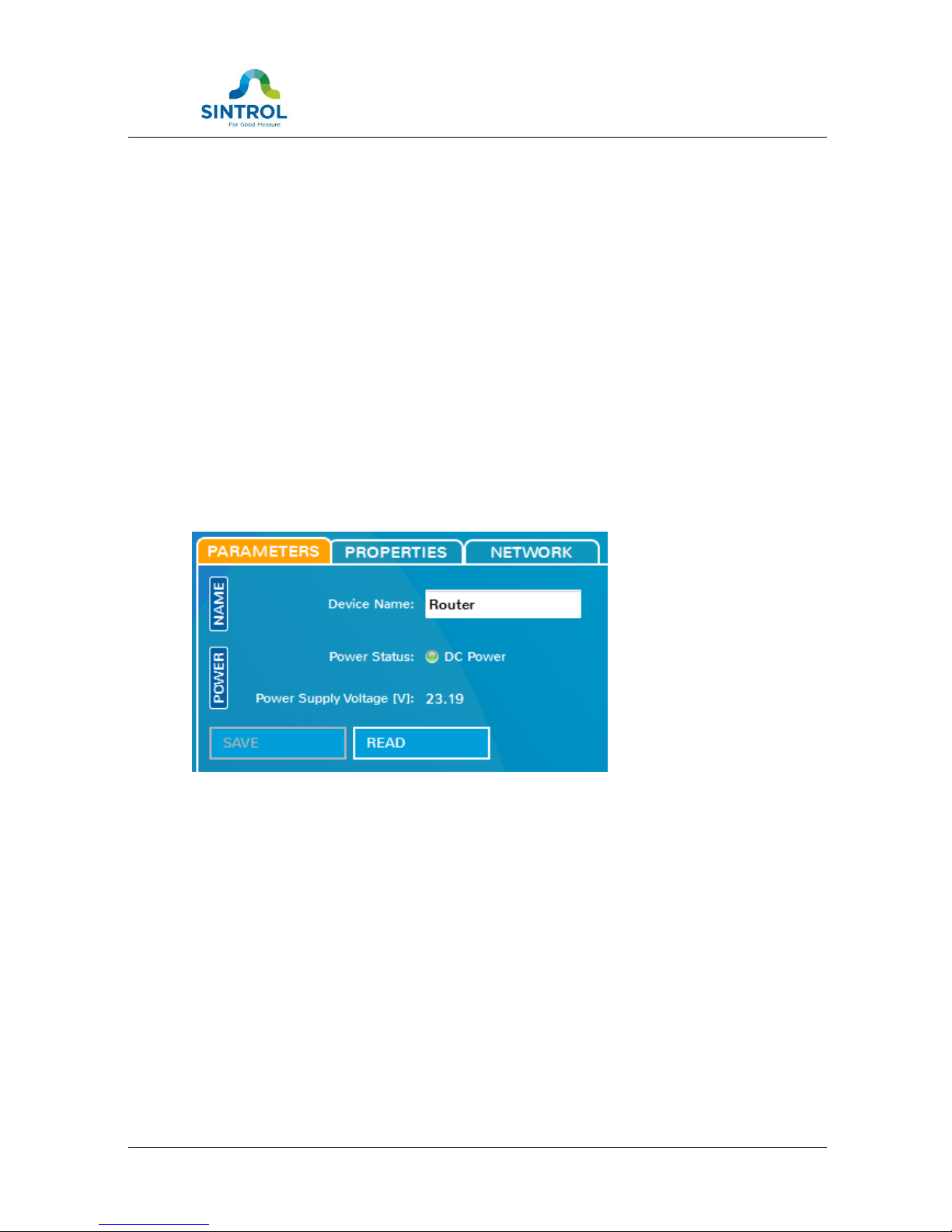
On the parameters tab the router name can be changed in order to easier identify
the unit.
Device also measures the power source it is connected to and shows the measured
input voltage for diagnostic reasons. If no input voltage can be detected, the
device is not fully working.
Figure 4 Parameters tab
Page 11

Wireless Router User Manual 11
5.2 PROPERTIES
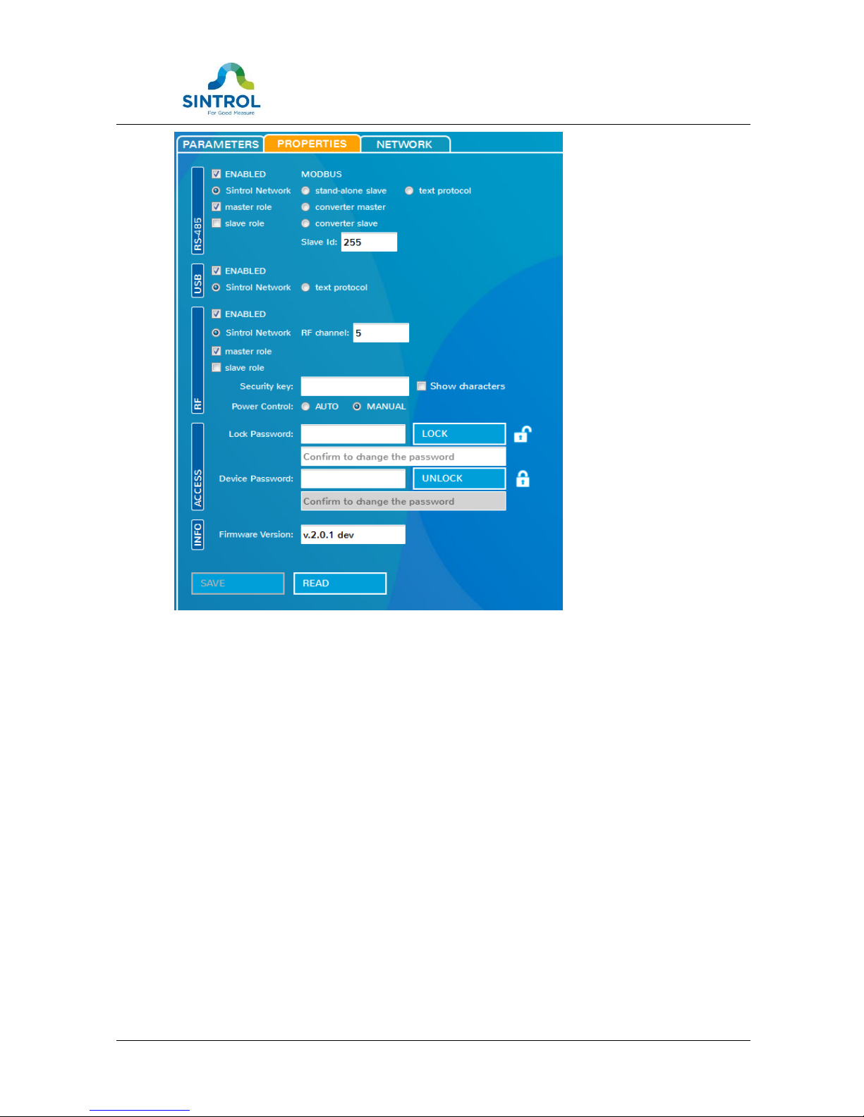
Wireless Router controls the network communication of the RS485 and RF. On the
properties tab it is possible to set different behaviors for the unit, which will affect
the whole communications network.
NOTE: Changing default setting on the properties tab may result in communication
malfunctions or even losing the control over the Wireless Router.
RS485
When device is operating as a router, the RS485 role must always be set to Sintrol
Network as a network master. Integration the unit with MODBUS-protocol is
beyond this document.
USB
When device is operating as a wireless router, the USB must always be enabled
and set to Sintrol Network. Setting protocol to ‘text protocol’ will disconnect the
device from PC-software and should only be used by trained service personnel.
RF
When device is operating as a wireless router, the unit operates in Sintrol Network
as a network master.
When building a new RF-network, the actual communication channel can be
chosen in between 0 and 254. The default channel in Sintrol products is preset to
0. In case of existing RF-communication on channel 0, it is recommended to select
a different channel.
NOTE: If the channel of the router should be changed, it means that it is also
required to change all the network device’s channels also!
The recommended channels numbers are from 0 to 15. A channel number is the
number of steps added into the base frequency. One step is exactly 199,951 kHz.
Security key
For the whole network, an optional security key can be assigned. This key will close
the network so, that no new devices can be added into the network without this
key.
Lock password
Lock password will lock all the parameters of this unit. In order to change any
parameters after locking the device, it needs to be unlocked with the correct
password. Do not lose the password!
Device password
This is the unique factory password of the device that can be used to open in-built
device specific debug and maintenance features of the device.
This feature can be used ONLY by approved Sintrol Service personnel.
Page 12
Wireless Router User Manual 12
Figure 5 Properties tab
Page 13
Wireless Router User Manual 13
5.3 NETWORK
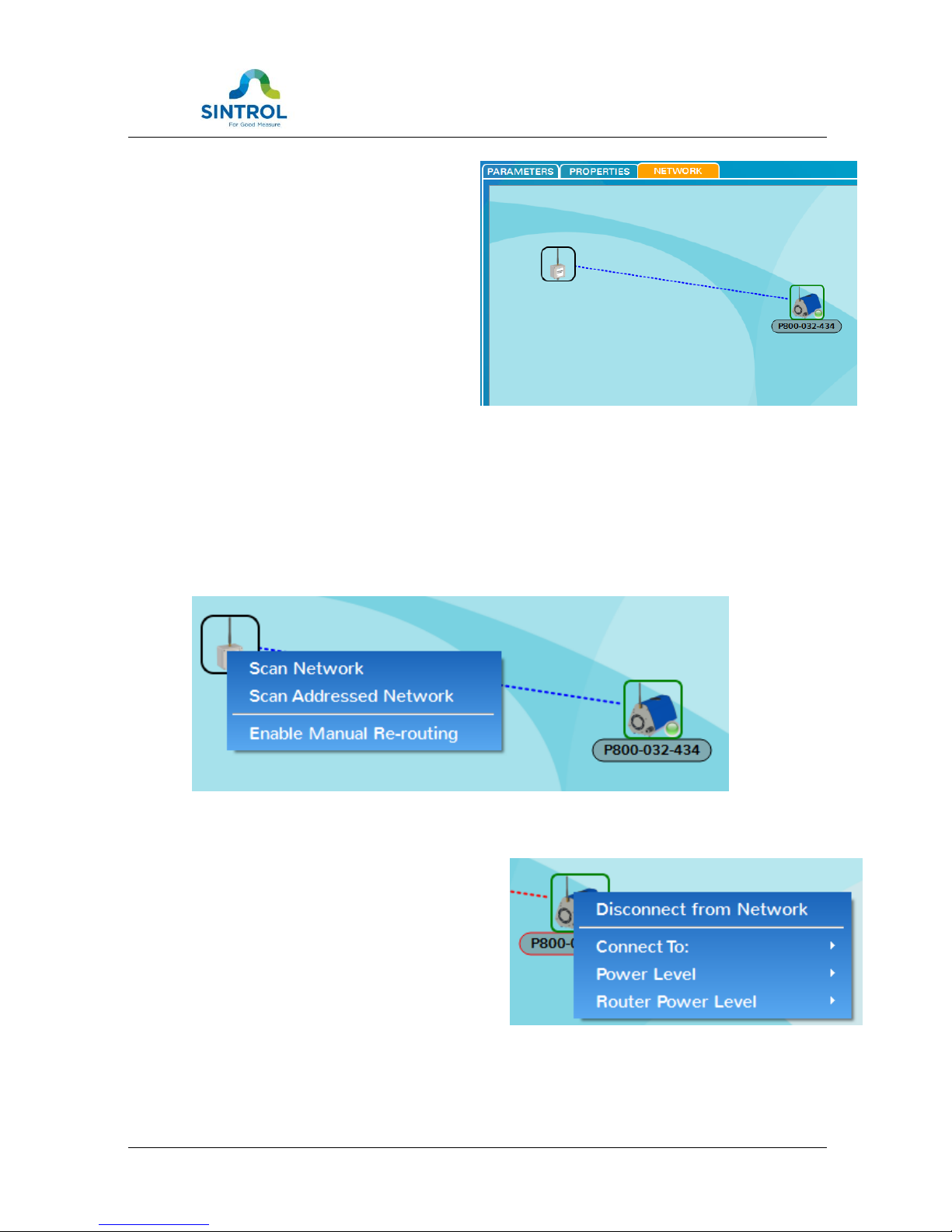
On the network tab one can manage
the current Sintrol Network routing
and topology. The graphical
presentation of connections shows
links within the Sintrol Network:
Dotted line between units present the
RF connection and solid lines stand for
the RS485-wires.
Modifications on the network are
done via menu that appears by rightclicking the desired node/unit.
Create the network
By right-clicking the Wireless Router itself a control menu appears. From the menu
it is possible to scan the network, in order to add new devices. Sintrol devices that
are not a part of any network, will appear and join the new network automatically.
Before manual re-routing of devices within the network, action must be enabled
first by command ‘Enable Manual Re-routing’ from the router’s menu.
Figure 6 Router menu
Manually routing the devices
To get started with re-routing the devices,
first one must right-click the Wireless
Router and enable Manual routing for the
network.
When the manual routing is enabled, the
devices in the network can be right-clicked
and via the menu:
1. Disconnected from the network.
Page 14

Wireless Router User Manual 14
The device will disappear from this network and stay ready to join other
networks.
2. Moved around the network by reconnecting them into another node
(device) within the network.
Every Sintrol network device can be selected as a link.
3. Or their RF-transmission power levels can be adjusted.
Each device has a setting of their own RF-transmission levels for upstream
and downstream, which can be manually adjusted.
Transmission power level options
Each RF-link within the Sintrol Network has it’s own transmission power levels in
order to ensure best possible operation and minimal interference with possible
other networks within the area.
Transmission power level setting is also directional and device role dependent.
Every device within the Sintrol Network has a separate upstream and downstream
transmission levels. Upstream level is used with transmission towards the network
root node (towards the Wireless Router) as the downstream transmission level is
used to communicate with the devices further away in the network.
Wireless Router operates as the root node of the network and thus has no
upstream level at all. However, the Wireless Router manages unique transmission
levels for each first level devices in the network independently.
Usage of transmission power levels
Links between nodes in RF-network work generally most reliably, when the
transmission levels match the receiver sensitivity. The transmission level settings
of Sintrol Network provide a flexible and powerful way to optimize the reliability of
communication.
The error levels of a received message is highly dependent on the distance
between the two devices. Also the conditions in between the devices, like
structures (f.ex. metal and concrete) typically have a notable role in dampening or
reflecting the RF-signals.
In some cases it is also possible that devices may receive the transmitted signal
way too well due to reflections or very close distance. In this case it would be in
order to lower the transmitting level of the link to ensure best possible reliablility
of the message transmissions.
Page 15

Wireless Router User Manual 15
6 MAINTENANCE
After automatic setup, the Wireless Router needs very little or no maintenance.
However, keeping the product’s surface and especially the antenna clean of dust or
any other substance, is recommended.
7 TROUBLESHOOTING
7.1 No USB-connection to PC
Check that the device is powered up.
Check that Sintrol DustLog software has been installed correctly.
o Ensure that USB-drivers have been installed correctly and the
operating system recognizes the device correctly.
7.2 No response over RF
Is the antenna mounted correctly and not covered by items or dirt.
Is the end device powered up?
Are the Wireless Router and the end device set into the same RF-channel?
Is the distance between Wireless Router and the end device within the given
operating distances? Both devices have their nominal operating distance
stated in their technical datasheet, based on the selected antennas.
Are the transmission power levels set correctly? Check the level first from the
upstream node.
Is the network device powered up and working correctly?
Is the network device already part of another network? If so, establish the
connection via USB and detach the network device from the old network
according to the instructions on the manual for the specific device.
7.3 No response over RS485
Is the end device powered up and is the polarity of the RS-485 wires correct?
Is the RS-485 bus terminated according the standard/specification?
Is there any other communication or master units on the RS-485 currently
present?
Is the network device powered up and working correctly?
Page 16
Wireless Router User Manual 16
Is the network device already part of another network? If so, establish the
connection via USB and detach the network device from the old network
according to the instructions on the manual for the specific device.
NOTES
Page 17

Wireless Router User Manual 17
SINTROL Oy
Ruosilantie 15
00390 Helsinki
Finland
Tel +358 9 5617 360
Fax +358 9 5617 3680
www.sintrolproducts.com
 Loading...