

Page 1

Sinteck Sistemas Eletrônicos Ltda.
Sinteck
Sistemas
Electrónicos
Calle Sotavento 3-13
Valencia - España
+34 961777172
Rua dos Bolivianos 578
Sao Paulo - Brasil
+55 11 61438640
Technical Manual
Strider RPU&STL Link Series
Reportage Link System packages
Studio-Transmitter Links
Auxiliary Link System
SUMMER05-SRFStrider-161004A
Released
February - 2005
Sao Paulo
Page 2
Sinteck Sistemas Eletrônicos Ltda.
P/02
Page 3

Strider Link Series
SRFStrider-161004A-REV.A
Sinteck Sistemas Eletrônicos Ltda.
PT
PT
ESP
ESP
Estamos gratos pela confiança em nós depositada ao
optar por um produto Sinteck.
Strider Link faz parte da estratégia Sinteck de chegar cada vez mais perto das
necessidades, anseios e expectativas de nossos clientes. Surpreender, inovar, adicionar
novos recursos de design, requinte, tecnologia e confiabilidade são propósitos que
permeiam cada etapado desenvolvimento deum novo produto.
Concebido a partir destes critérios, Strider Link conjuga qualidade e segurança, com
excelentes indices de durabilidade, desempenho e economia. É a vitória de um projeto
desenvolvido no Brasil para extremas condições de temperatura, tensão de alimentação e
padrões brasileiros e inteiramente compativel com as exigencias de nossos usuários
internacionais.
Está em suas mãos um produto confiável, testado e aprovado pelos mais rigorosos
usuários, um produtosimples de usare sofisticado emtecnologia.
Gracias por la confianza depositada en nosotros por
haber elegido un producto Sinteck.
Strider link surge a partir de la estrategia Sinteck en llegar cada vez más cerca de
las necesidades, anhelos y expectativas de nuestros clientes. Sorprender, innovar,
introducir continuas mejorias en el diseño, perfección, tecnología y confiabilidad
son algunos de nuestros propósitos que permedian cada etapa de la evolución y
desarrollo de unnuevo producto.
En base a estos criterios, Strider Link combina calidad y seguridad, con excelentes
índices de durabilidad, desempeño y economía. Es el logro de un proyecto
desarrollado en Brasil que responde a elevadas temperaturas climatológicas,
tensión de alimentación y padrones brasileños completamente compatibles con las
exigencias de nuestrosusuarios internacionales.
Tiene en sus manos un producto confiable. Testado y aprobado por los más
rigurosos usuarios, unproducto simple deutilizar y sofisticado en tecnología.
ENG
ENG
P/03
Thank you for putting your trust in us by choosing a
Sinteck product.
This Strider Link equipment is growing as part of the Sinteck strategy is responding
to the needs of today, as requested and expected by our clients. By introducing
innovating and reliable designs, we can build up a trusting relationship with our
customers.
At the forefront of this criteria, Sinteck’s Strider Link Series combines both quality
and security, with excellent qualities of durability, design and economics. This
equipment is the result of a project developed in Brazil that responds to withstand
extreme summer temperatures in our local market and compatible with the need of
our international users.
You have a product at hand that is reliable, tested and proved by the most
demanding users, aproduct that is simple to use and highly technically advanced.
Page 4

AA- Preliminary Instructions
Strider Link Series
SRFStrider-161004A-REV.A
Sinteck Sistemas Eletrônicos Ltda.
This manual is written as a general guide for those having previous knowledge and
experience with this kind of equipment, well conscious of the risks connected with
the operation ofelectrical equipment.
It is not intended to contain a complete statement of all safety rules which should be
observed by personnelin using thisor other electronic equipment.
The installation, use and maintenance of this equipment envolve risks both for the
personnel performing them and for the device itself, that shall be used only by
trained personnel.
Sinteck Nextt doesn’t assume responsibility for injury or damage resulting from
improper procedures orpractices by untrainedpersonnel in this handling of this unit.
Please, observeall local codes andfire protection standards in the operationsof this
unit.
Warning: always disconnect power before opening covers or removing any
part of this unit.
Use appropriate grounding procedures to short out capacitors and high
voltage points before servicing.
Warning: this devicecan irradiateradio frequency waves, and it’s not installed
following the instructions contained in the manual and local regulations it
could generate interferences in radio communications.
This is a “ Class A” equiment. In the residential place this equipment can
cause hash. In this case can be requested to user to take the necessary
measures.
Sinteck Nextt reserves to the right to modify the design and/or the technical
specifications of theproduct and this manual without notice.
P/04
Page 5

BB- Warranty
Strider Link Series
SRFStrider-161004A-REV.A
Sinteck Sistemas Eletrônicos Ltda.
All products madeby Sinteck Nexthas 2 yearslimited warranty.
Sinteck Next extends to the original end-user purchaser all manufacturers warranty which
are transferrable andall claims areto be madedirectly to Sinteckper indicated procedures.
The limited warrantynot includes:
1) Re-shipment ofthe unit toSinteck Next forrepair purposes,
2)Any unauthorized repair/modification,
3) Incidental/consequential damagesas a resultof any defect,
4) Nominal non-incidentaldefects,
5) Re-shipment costsor insurance ofthe unit orreplacement units/parts.
Any damage tothe goods mustbe reported tothe carrier inwriting on theshipment receipt.
Any discrepancy or damage discoveredsubsequent todelivery, shall be reported toSinteck
Next within 5(five) days fromdelivery date.
Toclaim your rightscovered by thislimited warranty,you must followthese procedures:
1) Contact the dealer or distributor where you purchased the unit. Describe the problem
and, as soonas possible easysolution can betaken.
Dealers and distributors are supplied with all information about problems that may occur
and usually they can repair the unit quickly. Almost all errors when installing the devide are
detected by thedealers and distributors.
2) If your dealer is not able to assist you, contact Sinteck Next and report the problem. If it is
decided to return the unit to the factory, Sinteck Next will mail you a regular authorization
with all the necessary instructions to send back the goods. In some cases the device must
be re-shipped back to the Sinteck Labs - Then, contact Sinteck Next and request an
authorization number.
3) When you receive the authorization, you can send back the unit. Pack it carrefully for the
shipment, preferably using the original wood box and seal the package perfectly. The
customer always assumes the risks of loss (remember: Sinteck Next is never responsible
for damage or loss), until the package reaches Sinteck Labs. For this reason, we suggest
you to insure the goods for the whole value. Shipment must be effected in the prepaid form
to the addressspecified by Sinteck’s service manageron the authorization.
IN ANY CASE, DO NOTSEND BACK UNITS WITHOUT OUR AUTHORIZATIONAS THEY
WILLBE REFUSED.
4) Make sure to enclosea writtentechnical reportwhere mention all the problems found and
a copy ofyour original invoiceestablishing the startingdate of thewarranty.
Replacement and warranty parts may be ordered from the following address. Make sure to
include the equipmentmodel and serialnumber as wellas part descriptionand part number.
IN EUROPE: IN AMERICAS:
Sinteck Sistemas ElectrónicosSLL Sinteck Sistemas Eletronicosltda.
Calle Sotavento 3-13 Rua Dos Bolivianos578
El Perellonet Vila Rio Branco- Sao Paulo/SP
Valencia - España BRASIL
46012 CEP 03873-100
Telf.+55 116143 8640
P/05
Page 6

1
1.1 INTRODUCTION
The Strider Link Series RPU&STL, Reportage Link System, Studio Transmitter Link and Auxiliary
Link System is a simple system designed to convey FM program material from a studio site to a
transmitter site like STL use. Also, it can be used like Reportage link when exists the need to
transmit parties, games, events and too many others applications. The Strider Link Series also
simultaneously conveys control and secondary programming subcarriers through MPX inputs.
This equipment may also be used to provide high-quality program transmission in intercity relay
service.
The Strider Link Series of equipment is a family of equiment that can operate in sveral bands from
170MHz through 450MHz. Strider STL Professional Link Series can operate up to 2,5GHz. This
operate manual covers the 170MHz, 200MHz, 300MHz and 400MHz bands of operation and the
various configurations inthose bands.
Cards available to 2 different configurations:
The Strider Link system can be configured through cards that can be introduced by the customer
or even configured of it already manufactures internally with these cards. The customer can
choose in working with the basic system without additional card and according to need the cards
can be supplied.
The Strider Transmitter Link can work with a Stereo Generator Card to transmit programs in
Stereo operation.This card is very easy to install when the Strider Link package is bought without
any card.
Also, the second option is the Audio Processor Card, the user can choose to work with this card
and the Stereo Generator Card, the transmittion will have excellent audio quality with these two
cards.
Main Features:
In all of versions there is a LCD Display. RF, audio level, channel and other parameters are shown
on this LCD display. This display offers a very easy method of transmitter parameter monitoring
and a new level of easy for setup and installation, with metering accuracy normally only found on
expensive test equipment.
The FM modulator section in the Strider transmitters employs a fast PLL system and an excellent
VCO for extremelylow audio distortion andhigh stereo performance.
A built in audio modulator provides crystal clear stereo sound and combined with the internal
compressor/limiter a fully compliant “plugand play”all in one link systemon theStrider Multiplexx
with cards.
For future compatibility all settings are switchablewith on board jumpers. The stereo and/or limiter
settings can be switched in and out to suit the requirements of any external broadcast equipment
you may havenow and in thefuture (in theStrider Multiplexx - allcards installed)
The lightweight universalmains input designensures a highreliability efficient designcompatabile
with any mainssystem in the world.
1-2 System Characteristics
Strider Link Series
SRFStrider-161004A-REV.A
Sinteck Sistemas Eletrônicos Ltda.
01/P/06
Page 7

1
1.2 System Specifications
1.2.1 Strider Link Series - Composite System Characteristics
Frequency Range: 200MHz
300MHz
400MHz
Sub-bands of 5MHz, example: 350-355MHz
Channel Spacing: 25kHz,
50kHz,
100kHz
others on request
Frequency response: +-0.2dB or better, 30Hz to 53kHz
+-0,3dB or better, 30Hz to 75kHz
Distortion:
THD and IMD: 0,2% or less, 30Hz to 7,5kHz
(Typically better than 0,15% at 1kHz)
[Convolved stereo demodulation products greater than 50dB
Below the 100% modulation reference level (400Hz) from 7,5-15kHz]
Stereo Separation: 55dB or better, 50Hz to 15kHz
(Typically 60dB or better)
Signal-to-noise ratio: 65dB or better
(Typically 70dB)
Demodulated, de-emphasized (left or right)
Referenced to 100% modulation
Emision: 500F9
1.2.2 Strider Link Series - Monaural System Characteristics
Distortion: +-0,3dB or better, 30hz to 15kHz
THD and IMD 0,15% or less, 30Hz to 15kHz
(Typically better than 0,1% at 1kHz
Signal-to-noise ratio: 70dB or better
(Typically 75dB)
Referenced to 100% modulation
Operating temperature: -10 C to +70 C
Emission: 110F3 (no subcarrier)
110F9 (with 26kHz control subcarrier)
230F9 (with 67kHz program subcarrier)
1-3 System Characteristics
Strider Link Series
SRFStrider-161004A-REV.A
Sinteck Sistemas Eletrônicos Ltda.
01/P/07
Page 8

1
1.2.3 Strider Link Transmitter - Basic Transmitter system - without cards
Type: Solid State
Direct FM
Frequency Synthesized
Crystal referenced
RF Power Output: 8W tipically, 10W maximum, adjusted in steps of
+-100mW.
RF Output Connector: 50 Ohms N connector type, UHF female on request
Deviation (100% modulation): +-75kHz
+-50kHz (composite)
+-40kHz (monaural)
Frequency Stability: +-5ppm or better (1 or 2 ppm on
request)
Spurious & Harmonic Emission: More than 60dB below carrier level
Modulation Capability: Mono operation and Composite main
subcarrier channels
Modulation inputs: Composite: 0dBm nominal for 75kHz deviation @ 1kHz
adjustable - MPX input BNC connector 10k Ohms unba lanced.
Frequency range: 30Hz to 200kHz
(1 BNC connector unbalanced)
Monaural: 0dBm nominal for +-75kHz deviation @ 1kHz
, (internal jumpers for -10dB or +6dB)
XLR connector - balanced electronic floating - 600 ohm
Frequency range: 30Hz to 20KHz
Mono input is made by the LEFT XLR connector
(Internal jumper to 50µs or 75µs pre-emphasis selection)
SCA input: 0dBm nominal for +- 7,5kHz deviation at
57kHz adjustable
Impedance: 10k Ohms
Frequency Range: 50kHz up to 200kHz
BNC connector unbalanced
Power Source: 85 to 265VAC 47-63Hz switched power
supply system, full-range 48W.
12VDC input socket for mobile operation
(Minimum 10,8V and maximum 14V)
Dimensions: 1 rack unit (44,45mm) high
483mm wide
12,5 cm deep
Shipping Weight: 3,5kg
1-4 System Characteristics
Strider Link Series
SRFStrider-161004A-REV.A
Sinteck Sistemas Eletrônicos Ltda.
01/P/08
Page 9

1
1.2.4 Strider Link Transmitter - W/ Audio processor dual-band card
Type: Solid State
Direct FM
Frequency Synthesized
Crystal referenced
RF Power Output: 8W tipically, 10W maximum, adjusted in steps of
+-100mW.
RF Output Connector: 50 Ohms N connector type, UHF female on request
Deviation (100% modulation): +-75kHz
+-50kHz (composite)
+-40kHz (monaural)
Frequency Stability: +-5ppm or better (1 or 2 ppm on
request)
Spurious & Harmonic Emission: More than 60dB below carrier level
Modulation Capability: Mono operation and Composite main
subcarrier channels
Modulation inputs: Composite: 0dBm nominal for 75kHz deviation @ 1kHz
adjustable - MPX input BNC connector 10k Ohms unba lanced.
Frequency range: 30Hz to 200kHz
(1 BNC connector unbalanced)
Monaural: 0dBm nominal for +-75kHz deviation @ 1kHz
, (internal jumpers for -10dB or +6dB)
XLR connector - balanced electronic floating - 600 ohm
Frequency range: 30Hz to 20KHz
Mono input is made by the LEFT XLR connector
(Internal jumper to 50µs or 75µs pre-emphasis selection)
SCA input: 0dBm nominal for +- 7,5kHz deviation at
57kHz adjustable
Impedance: 10k Ohms
Frequency Range: 50kHz up to 200kHz
BNC connector unbalanced
Audio processor dual-band card: Stereo active bass boost circuit 3dB @ 80Hz (punch)
Stereo crossover 6dB in-phase correction:
* Low pass: 30Hz to 200Hz - 1st way
* High pass: 200Hz to 15kHz - 2nd way
Stereo compressor and limiter section of the card:
* 1st way: attack time 10ms, release time 1s
* 2nd way: attack time 4ms, release time 500ms
Maximum compressionÇ >20:1dB
Power Source: 85 to 265VAC 47-63Hz switched power
supply system, full-range 48W.
12VDC input socket for mobile operation
(Minimum 10,8V and maximum 14V)
Dimensions: 1 rack unit (44,45mm) high
483mm wide
12,5 cm deep
Shipping Weight: 3,5kg
1-5 System Characteristics
Strider Link Series
SRFStrider-161004A-REV.A
Sinteck Sistemas Eletrônicos Ltda.
01/P/09
Page 10

1
1-6 System Characteristics
Strider Link Series
SRFStrider-161004A-REV.A
Sinteck Sistemas Eletrônicos Ltda.
01/P/10
1.2.4 Strider Link Transmitter - W/ Stereo Generator card
Type: Solid State
Direct FM
Frequency Synthesized
Crystal referenced
RF Power Output: 8W tipically, 10W maximum, adjusted in steps of
+-100mW.
RF Output Connector: 50 Ohms N connector type, UHF female on request
Deviation (100% modulation): +-75kHz
+-50kHz (composite)
+-40kHz (monaural)
Frequency Stability: +-5ppm or better (1 or 2 ppm on
request)
Spurious & Harmonic Emission: More than 60dB below carrier level
Modulation Capability: Mono operation and Composite main
subcarrier channels
Modulation inputs: Composite: 0dBm nominal for 75kHz deviation @ 1kHz
adjustable - MPX input BNC connector 10k Ohms unba lanced.
Frequency range: 30Hz to 200kHz
(1 BNC connector unbalanced)
Monaural: 0dBm nominal for +-75kHz deviation @ 1kHz
, (internal jumpers for -10dB or +6dB)
XLR connector - balanced electronic floating - 600 ohm
Frequency range: 30Hz to 20KHz
Mono input is made by the LEFT XLR connector
(Internal jumper to 50µs or 75µs pre-emphasis selection)
SCA input: 0dBm nominal for +- 7,5kHz deviation at
57kHz adjustable
Impedance: 10k Ohms
Frequency Range: 50kHz up to 200kHz
BNC connector unbalanced
Stereo Generator Card: Jumper selection 50µs or 75µs
Frequency response: 20Hz to 15kHz (THD+N<0,1%)
(when installed the digital 15kHz low pass filter)
Stereo separation: Better than 60dB @ 1kHz
Pilot tone frequency: 19kHz +- 1Hz
Power Source: 85 to 265VAC 47-63Hz switched power
supply system, full-range 48W.
12VDC input socket for mobile operation
(Minimum 10,8V and maximum 14V)
Dimensions: 1 rack unit (44,45mm) high
483mm wide
12,5 cm deep
Shipping Weight: 3,5kg
Page 11

1
1.2.6 Strider Link Transmitter - Multiplexx (Stereo Generator card + Audio processor dualband card + Digital 15kHz low pass filter card)
1-7 System Characteristics
Strider Link Series
SRFStrider-161004A-REV.A
Sinteck Sistemas Eletrônicos Ltda.
01/P/11
Type: Solid State
Direct FM
Frequency Synthesized
Crystal referenced
RF Power Output: 8W tipically, 10W maximum, adjusted in steps of
+-100mW.
RF Output Connector: 50 Ohms N connector type, UHF female on request
Deviation (100% modulation): +-75kHz
+-50kHz (composite)
+-40kHz (monaural)
Frequency Stability: +-5ppm or better (1 or 2 ppm on
request)
Spurious & Harmonic Emission: More than 60dB below carrier level
Modulation Capability: Mono operation and Composite main
subcarrier channels
Modulation inputs: Composite: 0dBm nominal for 75kHz deviation @ 1kHz
adjustable - MPX input BNC connector 10k Ohms unba lanced.
Frequency range: 30Hz to 200kHz
(1 BNC connector unbalanced)
Monaural: 0dBm nominal for +-75kHz deviation @ 1kHz
(internal jumpers for -10dB or +6dB)
XLR connector - balanced electronic floating - 600 ohm
Frequency range: 30Hz to 20KHz
Mono input is made by the LEFT XLR connector
(Internal jumper to 50µs or 75µs pre-emphasis selection)
SCA input: 0dBm nominal for +- 7,5kHz deviation at
57kHz adjustable
Impedance: 10k Ohms
Frequency Range: 50kHz up to 200kHz
BNC connector unbalanced
Audio processor dual-band card: Stereo ac tiv e bass boost circuit 3dB @ 80Hz (punch)
Stereo crossover 6dB in-phase correction:
* Low pass: 30Hz to 200Hz - 1st way
* High pass: 200Hz to 15kHz - 2nd way
Stereo compressor and limiter section of th e card :
* 1st way: attack time 10ms, release time 1s
* 2nd way: attack time 4ms, release time 500ms
Maximum compressionÇ >20:1dB
Stereo Generator Card: Jumper selection 50µs or 75µs
Frequency response: 20Hz to 15kHz (THD+N<0,1%)
(when installed the dig ital 15kHz low pass filter)
Stereo separation: Better than 60dB @ 1kHz
Pilot tone frequency: 19kHz +- 1Hz
Power Source: 85 to 265VAC 47-63Hz switched power
supply system, full-range 48W.
12VDC input socket for mobile operation
(Minimum 10,8V and maximum 14V)
Dimensions: 1 rack unit (44,45mm) high
483mm wide
12,5 cm deep
Shipping Weight: 3,5kg
Page 12

1
1.2.7 Strider Link Receiver
RF Input Connector: 50 Ohms type N Female, or UHF Female
on request
Sensitivity: Composite: 100µV or less required
for 65dB SNR, left or right channel de emphasized, demodulated.
Monaural: 20µV or less required for 65dB SNR
Selectivity:
Composite: 3dB IF bandwidth: +- 125kHz
80dB IF bandwidth: +- 1,2MHz
Monaural: 3dB IF bandwidth: +-90kHz
80dB IF bandwidth: +-1,2MHz
Modulation outputs: Composite: 4Vpp @ 600 Ohms, adjustable
unbalanced
Frequency range: 30Hz to 80kHz
(1 BNC Connector)
Monaural: 0dBm @ 600 Ohms, balanced
Frequency range: 30Hz to 15kHz
(1 XLR Connector)
Stereo decoder outputs:
0dBm @ 600 Ohms, balanced
Frequency range (Left or Right): 30Hz to
15kHz
(2 XLR Connector, 1 Left Signal out, 1
Right Signal out)
Stereo demodulated separation: 40dB or
better.
Power Source: 100/120/220/240VAC 50Hz - 60Hz
15W Max
Dimensions: 1 rack unit (44,45mm)
483mm wide
125mm deep
Shipping Weight: 2,5kg domestic
1-8 System Characteristics
Strider Link Series
SRFStrider-161004A-REV.A
Sinteck Sistemas Eletrônicos Ltda.
01/P/12
Page 13

1.3 System Features
In addition to establishing a new industry standard for performance, the Strider Link Series incorporates
many new and innovative features to aid in the installation, operation and maintenance of a system. Some of
the new features are:
* Very low distortion ceramic IF Filters offering unprecedented selectivity.
* Peak reading meter for all major functions.
* Decade logarithmic true signal strenght meter
* Channel marker and easy channel change.
* Important status functions implemented with LED indicators
* Designed to have a minimum of adjustments for trouble-free operation. Very easy to use.
* Modular construction that provides excellent shielding and at the same time allows easy access to
components.
* Multichannel Option: The Strider Link Series offers a large band of channels, in some models there are 40
Channels.
It is recommended that the manual be studied at least through Section 5 before
attempting to install the system.
1.4 Safety
1.4.1 Mains Voltage
This equipment operates from an AC power source of between 85 and 265V. There are hazardous voltages
present internally. PLEASE OBSERVE CAUTION WITH THE COVER REMOVED.
1.4.2 Swithed Mode Power Supply Hazard
Please note that the power supply units in this equipment is of the switched mode variety and have lethal
voltages present internally. The switched mode supplies are universal input fully approved type. They are non
serviceable modules and should be fully replaced should they fail.
1.4.3 Fuses
Only use fuses with the specified voltage and current ratings as stated on the back panel or pcboard. Failure
to do so may increase the risk of equipment failure, shock and fire hazard.
1.4.5 Radio Frequency
The N type RF power output socket contains RF voltages which may burn or present a shock. Please make
sure that the equipment is connected to an adequately rated load or antenna system while in operation.
1.4.6 Toxic Hazard
This equipment includes RF components that may contain Beryllium Oxide which is a highly toxic substance
that could be hazardous to health if inhaled or ingested. Care should be taken when replacing or discarding
such devices. Seek expert advice from the manufacturer should you physically damage a device that
contains Beryllium Oxide.
The main RF output power module contains Beryllium Oxide.
1.4.7 Other Safety Considerations
Do not operate this equipment in the presence of flammable gases, fumes or liquids
Do not expose this equipment to rain or water.
1
1-9 System Characteristics
Strider Link Series
SRFStrider-161004A-REV.A
Sinteck Sistemas Eletrônicos Ltda.
01/P/13
Page 14

2
2-1 Front and rear panels - Strider Transmitter Link
Strider Link Series
SRFStrider-161004A-REV.A
Sinteck Sistemas Eletrônicos Ltda.
FUSE
1 2 345 6 7
8
1110 12
13 14 15 16 17 18 19
8 - RF output connector - N type 50 Ohms2- Status Leds:
1st: On power
2nd: PLL locked
3nd: RF ON
4nd: Stereo ON
3 - Remote control sensor (not available)
4 - LCD monitoring display
6 - Down Button
5-UPButton
1- Power On/Off - Key 7 - Select Button
9 - FAN airflow out
10 - Input SCA BNC connector
11 - Input MPX BNC connector
12 - 19kHz output (1VPP) for RDS coders
13 - SCA level adjust (multi-turn trimmer)
14 - MPX level adjust (multi-turn trimmer)
15 - XLR connector - Mono or left signal input 600 ohms
16 - XLR connector - Right signal input 600 ohms
17 - FAN airflow out
18 - Input 12V DC - battery - connector
19 - Power Socket and fuse
02/P/14
Page 15

2
2-2 Front and rear panels - Strider Receiver Link
Strider Link Series
SRFStrider-161004A-REV.A
Sinteck Sistemas Eletrônicos Ltda.
1 2 3 4 567
8
910
11 12 13 14 15
8 - RF input connector N type 50 Ohms2- Status Leds:
1st: On power
2nd: PLL locked
3nd: Remote ON
4nd: Stereo decoder ON
3 - Remote control sensor (not available)
4 - LCD monitoring display
6-DownButton
5-UPButton
1- Power On/Off - Key 7 - Select Button
9 - MPX output - BNC connector
10 - XLR connector - Mono output 600 ohms
11 - XLR connector - Right signal output 600 ohms
12 - XLR connector - Left signal output 600 ohms
13 - Remote Relay contacts
14 - AC selector switch
15 - Power Socket and fuse
02/P/15
Page 16

2
2-2 Block Diagram - Strider Transmitter Link
Strider Link Series
SRFStrider-161004A-REV.A
Sinteck Sistemas Eletrônicos Ltda.
02/P/16
EMI-RFI FILTER
EMI-RFI FILTER
EMI-RFI FILTER
AUDIO PROCESSOR
DUAL BAND
CARD
SOFT-CLIPPER 15KHZ
LOW PASS FILTER
CARD
STEREO GENERATOR
CARD
EMI-RFI FILTER
EMI-RFI FILTER
SCA
19KHZ
SYNC OUT
AUDIO SELECTOR CPU
LIQUID CRYSTAL DISPLAY
SELECT BUTTONS
VCO BLOCK
PHASE LOCKED LOOP
BUZZER STATUS LEDS
RF POWER
MODULE
RF
COUPLER
AC
SURGE
PROTECTION
AND FILTER
ALL SECTIONS AND MODULES
ALL SECTIONS AND MODULES
POWER SUPPLY
DC
SOCKET
+12 BATTERY
RF output
HARMONIC
FILTER
Page 17

2
2-2 Block Diagram - Strider Receiver Link
Strider Link Series
SRFStrider-161004A-REV.A
Sinteck Sistemas Eletrônicos Ltda.
02/P/17
EMI-RFI FILTER
EMI-RFI FILTER
EMI-RFI FILTER
EMI-RFI FILTER
AUDIO SECTION CPU
LIQUID CRYSTAL DISPLAY
SELECT BUTTONS
FM OSC
VCO BLOCK
PHASE LOCKED LOOP
BUZZER STATUS LEDS
PRESELECTOR FILTER
CAVITY
FILTER
AC
SURGE
PROTECTION
AND FILTER
ALL SECTIONS AND MODULES
ALL SECTIONS AND MODULES
POWER SUPPLY
MIXER AND IF 10,7 FILTERS
IF DEMODULATOR
STEREO DEMODULATOR
MUTE AND REMOTE CIRCUIT DETECTOR
LNA AMPLIFIER - 1
LNA AMPLIFIER - 2
RSSI
ON-OFF
Page 18

2
Strider Link Series
SRFStrider-161004A-REV.A
Sinteck Sistemas Eletrônicos Ltda.
2-2 Wiring and Internal Overview - Strider Transmitter Link
F1
GND
AC
AC
R12
J1
2A
LED
C16
C1
L2
C11
DS2
R5
R8
C19
CI3
C4
C5
C6
C15
R7
C14
D6
L1
VR1
CN1
D3
D4
D2
D1
-+
REV.01
CH2052
VOLTEC
ON
C12
C8
R2
C9
CI1
D
F
S
X
LC
DS1
D7
R4
T1
R9
C18
CI2
D8
C20
R1
D5
C7
C10
NT1
C3
C2
C21
R10
C17
C13
R6
CN2
R11
R3
ON
S2
S1
CLIP
+BAT
VCO
200MHZ -500MHZ
AUDIO VPLL +10V
GND
RF OUT
AUDIO HI-FI
STEREO/MONO
RIGHT INPUT
STEREO
LEFT INPUT
1
19KHZ
OUT
MPX INSCA IN
VL1
VL2
GND
+12V
LCD
BUZ ST
TEMP
RF OUT
AUDIO PROCESSOR
FILTER15KHZ 8Th
STEREO GENERATOR
RF
PLL
PLL BLOCK
FWDREF
MOD
SWR
VMOD
19K LEVEL
BAL.
VPA
IPA
VB
+
+ MONO
50uS/75uS
0dB ON
+6dB
+6dB
++
ADJ SCA
ADJ MPX
STRIDER TRANSMITTER
Version3.1
02/2005
ADJ
VPA
C1
C3
C4
C5
C6
C7
C8
C9
C10
C11
C12
C13
XR1
XR2
D1
D1
IND1
U1
DS1
IND2
C16
POT1
R1
R2
XR3
C17
D5
U2
XR4
C19
C21
C22
C23
C24
U3
C25
C26
C27
XR5
XR6
CN1
CN2
CN3
CN4
XR6
XR7
U4
U5
C28
XR8
XR9
XR10
U6
U7
U8
U9
U10
U11
U12
U13
PA1
XR11XR12
C29
C30
C31
C32
C33
C34
C35
C36
C37
C38
C39
F1
DZ2
X1
X2
C40
C41C42C43C44
C45
XR13
XR14
C46
C47
C48
C49
C50
C51
C52
XR15
XR16
XR17
L1
L2
D6
D7
Q2
Q3
Q4
Q5
Q6
Q7
Q8
CV1
D8
D9
DZ3 DZ4
DZ5
D10
DZ6
DZ7
DZ8
D11
D12
D13
D14
D15
D16
D17
D18
D19
CARD1
CARD2
CARD3
DS2
1
2
3
4
5
6
7
8
9
10
11
12
13
14
15
1 - RF output connector
2 - Fuse 4 amps. RF power
module
3 - BNC connector - SCA input
4 - BNC connector - MPX input
5 - BNC connector - 19kHz
sync output
6 - Strider Transmitter Link
main board
7 - XLR connector - Left/mono
input
8 - XLR connector - Right input
9 - DC socket - 12V input
battery
10 - AC socket - input AC
11 - Power supply board - Fuse
2 amps.
12 - Switch ON-OFF
13 - Status Leds
14 - Liquid Crystal Display
15 - Select Buttons
02/P/18
Page 19

V1
XR17
CN9
CN8
CN7
CN6
CN5
DB2DB1
D16
Z6
D15
Z5
D14
Z4
Z3
D13
D12
D11
X3
Q8
D10
D9
Z2
Z1
Q7
Q6
Q5
Q4
Q3
Q2
XR16
XR15
XR14
XR13
XR12
XR11
XR10
U19
X2
XR9
XR8
C58
C57
C19
C18
C17
C16
C56
C55
C54
C53
C52
C51
C50
C49
C48
C47
C46
C45
C44
C43
C42
C41
C40
C39
C38
C37
C36
C35
C34C33
C32
C31
C30
C29
C28
C20
C21
C22
C23
C24
C16
C15
C14
XR7
XR6
U18
XR5
GAIN
CV3
CV2
J3
J2
J1
X1
CV1
U15
U14
U13
U12
U11
U10
U9
U8
U7
U6
U5
U4
D8
XR4
XR3
U3
C13
C12
C11
XR2
XR1
C10
C9
C8
U2U1
D7
D6
R1
C7
C6
D5
D4
D3
D2
C5
C4
C3C2
F1
D1
RL1
CN4
TRAF1
CN3
C1
CENT1
VR1
CN2
CN1
10/2004
Version 3.0
STRIDER RECEIVER
250V 10A
FUSIVEL
REMOTE
CM NF NA
SELECT
AC INPUT
SWITCH
VOL2
VOL1
OFFON
FILTER
50us 75us
LCD
STBUZZER
MO/ST
75uS
ON/OFF
MUTE
REMOTE
TRSH
SEP.
MOD
VTUNE
SIGNAL
LEFT OUT
STEREO
RIGHT OUT
STEREO
MONO OUT
+
OUT
MPX
+
+12V
INPUT
RF
C27
C26
C25
L3
L2
L1
CBL1
Q1
FT3
FT2
FT1
LQ1
CV4
CV5
U17
U16
Strider Link Series
SRFStrider-161004A-REV.A
Sinteck Sistemas Eletrônicos Ltda.
2-2 Wiring and Internal Overview - Strider Receiver Link
2
1
2
3
4
5
6
8
10
7
11
12
13
14
16
15
1 - RF input connector
2 - RF Section
3 - BNC connector - MPX
output
4 - XLR connector - Mono
output
5 - XLR connector - Stereo
demod. Right output
6 - XLR connector - Stereo
demod. Left output
7 - Remote fuse. 10 amps.
8 - Remote socket 3 pins.
9 - AC selector switch
10 - AC socket input AC
11 - AC transformer (0-115+0115V / 15-0-15V / 1amp.)
12 - AC Power switch
13 - Status Leds
14 - Liquid Crystal Display
15 - Select Buttons
16 - Cavity Filter and
Preselector RF Filter
02/P/19
9
Page 20

3
3-1 System Description - Strider Transmitter Link
Strider Link Series
SRFStrider-161004A-REV.A
Sinteck Sistemas Eletrônicos Ltda.
3.1 Strider Transmitter Link - Multiplexx - Audio processor and stereo generator
cards
The Strider Transmitter Link is a high fidelity broadband FM transmitter with a power output
of 8 Watts. It iscapable of transmitting the programsignal andtwo multiplex subcarriers with
little degradation of signal qualityover one link. The linearity and FMnoise characteristics of
the direct FM oscillator are exceptional. The transmitter is modular in construction and
operation, and the system description givenbelow follows the signalflow through the varios
modules and itscards.
The system assembly drawings are located in Section “ Schematics” along with the
module schematics and system schematics are at the end of this manual.
Fm Synthesizer
The baseband signal from the audio inputs modulates the frequency modulated oscillator
(FMOSC) in the VCO Block. The FMOSC consists of a 170-450MHz ultralinear, very low
noise VCO whichis phase lockedto a crystal-controlledreference oscillator. The phaselock
loop contains the frequency programming mode which allow the synthesizer to be changed
in frequency steps of 250kHz (standard) 25kHz or 100kHz in some models. The RF signal
will deviate +-75kHz (composite) or +-50kHz (mono) from the carrier. The output power of
the VCO isapproximatelly 5 milliwatt.
RF 50mW amplifier
In to the VCO block, there is a smaller RF amplifier section, that amplifiers 5mW from the
VCO output to50mW through of2 transistors.
RF 8W amplifier
The RF amplifier module internally consists of a two-stage MOSFET design, which
amplifies the input signal (50mW typ.) To the nominal 8W transmitter output. The output is
filtered to attenuate all higher order harmonics to a level of at least -60dBc. The output is
sampled via a dual directional coupler with detectors that provide an indication of the
forward and reflected power of the RF amplifier.The final stage current and voltage is
sampled and meteredin this module.
Transmitter Control
The Transmitter Control section of the audio and powersupply board has several functions.
One of these is to sense the PLL LOCK detect signal from the RF module. If this module
goes out of lock, thenthe radiate control logic circuitprovides asignal tothe power supply to
turn off the +7,2 VDC supply to the RF power module, causing the transmitter to stop
radiating. Also, this section detects if the VSWR level is more than permised, so the
transmitter controlturn offthe DClevel to the RF power module.Allof these parameters can
be view throughthe LCD onthe front panel.
Metering and Status
The Metering and Status circuitry on the audio, Power Supply and RF sections conditions
the varioussystem parameter samples for accurate meterindications, and drives the status
LEDs on thefront panel.
03/P/20
Page 21

3
3-2 System Description - Strider Transmitter Link
Strider Link Series
SRFStrider-161004A-REV.A
Sinteck Sistemas Eletrônicos Ltda.
Power Supply (AC)
The Power Supply board located out of the main PC board of the Strider Transmitter Link
converts anyof AC voltages (full-range 85up to 265VAC)into the 12V regulatedand filtered
voltage.
In the main PC board of the Strider Transmitter Link, exist others four DC regulators that
supplies the voltages required for the operation of the transmitter. The outputs are: +10V, 10V and +5V for the most of the system electronics. A high current +7,2V supplies the RF
power module. +5Vsupplies only themetering section.
External Power Supply (DC)
The Strider Transmitter Link can be configurated for DC operation too. There is In the rear
panel a connector to connecting a +12V battery. Internally the transmitter has a switching
power supplies to provide the system voltages. The RF power module is supplied of +7,2V
through an auxilliary switching power supply that sure maximum power until the battery
presents low charge. This external battery can present 10,8V at minimum and 14V at
maximum voltages.
Audio Processor Card
Optional, the user can obtaincards forsimple connectionto the Strider Transmitter Link, the
first card is an audio processor dual-band, that processes independently low and high
frequencies, always maintaininghigh the dynamicsof the transmission.This processor can
be enabled or disabled in the front panel. The audio processed is limited and it won't
produce over-modulation inthe transmitter, in additionthe sound qualitywill be exceptional.
Stereo Generator Card
The Stereo Generator Card consists in an AMDSB/SC stereo generator of excellent audio
separation. Also, the user can choose if the transmittion will be in stereo or mono. The
parameters of thiscard can beviewed on theLCD of theequipment.
Digital 15kHz Low-pass Filter
The digital 15kHz filter card is indicated for who needs to transmit programming that the
audio frequency does’t pass of 15kHz. Is most important to place this card when is installed
the stereo generator card, because the high frequencies is not important to transmit in this
case.
03/P/21
Page 22

3
3-3 System Description - Strider Receiver Link
Strider Link Series
SRFStrider-161004A-REV.A
Sinteck Sistemas Eletrônicos Ltda.
The Strider Link Receiver series has two different types of receivers which are designed for
different RF environments. The most popular version is the “Link Receiver” that is a singleconversion receiver that provides maximum performance in all but the most demanding
environments. The model “Triple-C Link Receiver” is triple-conversion receiver which
provide maximum out-of-band and adjacent channel protection. The Triple-C exhibits
superior front end performance in the presence of extremely strong RF fields, as it uses
modules from thetime-proven Sinteck Next.
Both systems are selectable to support mono or composite operation. The receivers are
single in construction and operation, just one PC board, and the system description given
below follows thesignal flow inthe block diagramsreferenced above.
The model “Triple-C Link Receiver”is not explainedin this manual.
The system assembly drawings are located in section “schematics” along with the
module schematics and assembly drawings. The system block diagrams and system
schematics are at the end of this manual.
Preselector/Preamplifier - Front End
The Preselector/Preamplifier is located out of the main PC board of the receiver. The
antenna input signal is first passed through the preselector filter section, which is a threeelement helical bandpass filter with a 5MHz bandwidth with very low insertion loss. The
output of the preselector filter is fed to the preamplifier providing low-noise gain. The
postselector filter providesfurther filtering aswell as imagenoise rejection.
Preselector Filter and Booster
A second filter located on the preselector filter consists in other RF filter and amplifier
presenting high gainand low distortion.
Preamplifier
The output of the Booster is fed to the preamplifier on the RF section of the receiver. This
preamplifier incorporates an adjustable gain circuit and schockty barrier diodes attenuators
for user-adjustable front end protection and isolation. The low noise, high-intercept point
preamplifier is followedby the imagenoise filter.
Local Oscillator
The Local Oscillator consists of a 170-450MHz ultralinear, very low noise VCO which is
phase locked to a crystal-controlled reference oscillator. The phase lock loop contains the
frequency programming mode which allow the synthesizer to be changed in frequency
steps of 250kHz(standard) 25kHz or100kHz in somemodels.
Mixer and IFDemod
The mixer and IF Demod are located together the same component. A modern IC does the
both functions with the best performance. The carrier frequency provenient from the
Oscillator is mixed into the IC with the antenna signal to provide down direct-convesion to
the 10,7Mhz IntermediaryFrequency.TheIF is buffered to overcomemixer conversion loss.
The IF Demodmodule provides downconversion to the 10,7MHz,sets system selectivityin
this IF, extracts the baseband information from the carrier, provides the logarithmic RF
signal strength voltage for metering, and establishes the mute threshold point of the
receiver.
03/P/22
Page 23

3
3-4 System Description - Strider Receiver Link
Strider Link Series
SRFStrider-161004A-REV.A
Sinteck Sistemas Eletrônicos Ltda.
Audio/Baseband section
The main functions of the Audio/Baseband section on themain PC board ofthe receiver are
to split the baseband signal into three outputs: 30Hz to 75kHz to the MPX output BNC
connector.
For mono, the split is 30Hz to 15kHz to the Mono XLR connector.The usercan chooseif this
active filter inthis output isdisabled or enabledthrough internalljumpers. So, itis possible to
transmit 30Hz to 75kHz through this XLR connector. This module contains a mute switch,
controlled by the main processor and the mute comparator output of the Mute and Transfer
circuitry. The signal is then passed through a high frequency amplitude corrector, which
compensates for the baseband high-frequency roll-off caused by the 10,7MHz IF bandpass
filters, to restoreproper amplitude responseto the basebandsignal.
The signal level is adjusted by the processor, beetwen 0% and 100% (normally 0V to 4Vpp)
in both outputs,MPX and Mono.
For Stereo demod operation, 2 XRL connectors was placed, the Stereo demod section
provides an excellent stereo separation through a modern IC. In this point, the signal level
has not adjust and a fix level of 0dB normally is found in the 2 XLR outputs (left and right). To
mute the stereo demod, the user have to accede the internal jumpers, that originally come
no-muted (See “jumperssection - configurations”).
Mute and Transfer Section
The Mute andTransfer circuitry locatedin the mainPC board ofthe receiver mutesthe audio
signal during periods of insufficient RF signal strength orfor transferingoperation to another
receiver. This function is only available to the XLR connectors selectable by internal
jumpers, not forMono (XLR connector) and MPXoutput ( BNCconnector).
Metering and Status
The Metering and Status circuitry, located in the front panel PC board, condition the
metering samples and drives the status LEDs on the panel, also is possible to change any
parameter of the receiver, like choose channel and volume level. Remote status functions
are also provided.
Power Supply (AC)
The Power Supply section of the main PC board converts any AC input voltages
(110V/220V) into the three regulated voltages, required for the operation of the receiver.
The outputs are +12V,-12V and +5V for the most of thesystem electronics.Aregulated +5V
supply the mainprocessor and LCDdisplay backlight.
Remote Control
The Remote Control section in the receiver is a circuitry responsible to change the state of
the relay. This function is possible to connect auxiliary systems in the receiver, that will
change the state when the RF signal in the antenna is more than 10% of the maximum
signal. This parametercan be viewedthrough the LCDon the frontpanel.
03/P/23
Page 24

3
3-5 Quick guide for installation and use - Strider Transmitter Link
Strider Link Series
SRFStrider-161004A-REV.A
Sinteck Sistemas Eletrônicos Ltda.
This chapter contains the necessary instructions for the installation and use of the
equipment. In case some aspects are not totally clear, for instance when a user is using this
equipment for the first time, we advise the new user to read carefully the entire description
contained in thismanual.
3-2-1 Preparation
Unpack the transmitter unit and check, before making any operation, that the unit has not
suffered from any mishandling during the transport. In particular check that all the
connectors are inperfect conditions.
Check that thesupply voltage valuecoincides with theACvoltage available.
The input supplyfield is of:
Strider Transmitter Link: AC mains85 ~265V
Check that thepower switch of the StriderTransmitter Link isin the position“OFF”.
The Strider Transmitter Link has just one power switch, located inthe frontpanel, thisswitch
is responsible toconnect the AC poweror the DCpower (+12V battery).
Connect the RF output of the Strider Transmitter Link to the antenna cable or to a dummy
load adapted forthe working frequencyand the poweroutput used.
Connect the powercable to thecorresponding VDE socket.
REMARK: it is essential that the AC network has an accurrate grounding system order to
ensure both thesafety of theusers and thecorrect functioning ofthe unit.
If the user intends to use external batteries in caso ofAC supply interruption, connect them
to the clampssituated at theback of theequipment being carefulto respect thepolarity.
Connect the audio cables of your own audio signal to the apropriate connectors located at
the back ofthe Strider Transmitter Link.
3-2-2 Using
Switch on theStrider Transmitter Link byputting the powerswitch on theposition “ON’.
The following messagemust be viewed:
SINTECK
UHF TRANSMITTER
SINTECK
UHF TRANSMITTER
03/P/24
Page 25

3
3-6 Quick guide for installation and use - Strider Transmitter Link
Strider Link Series
SRFStrider-161004A-REV.A
Sinteck Sistemas Eletrônicos Ltda.
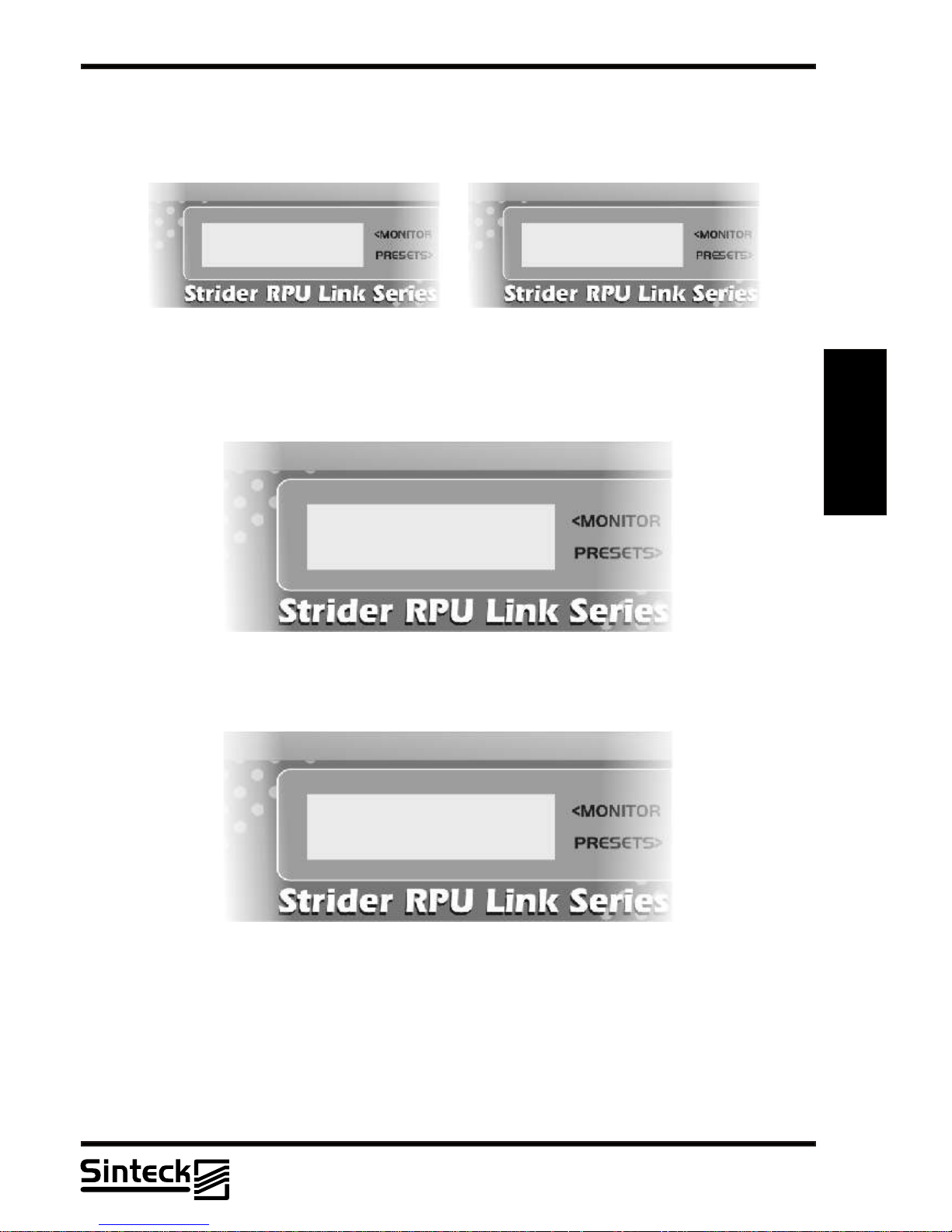
The unit is equipped with a LCD display with 2 lines on which several menus are shown. A
general view ofthe menus ofthe unit areshown in theillustration.
On the center of the display, depending on the case, the following symbol will be shown:
~
The parameter indicated can be modified in the menu CHANNEL, CONTRAST, RF
ADJUST, MPX SELECTION, INTERNAL MPX, AUDIO PROCESSOR, STEREO
GENERATORANDCONFIG HOLD..
When the unit is switched on, theLCD display shows the predefined view, with thegraphical
representation of thechannel set andstop there, likethe following sequence:
SINTECK
UHF TRANSMITTER
SINTECK
UHF TRANSMITTER
AUDIO PROCESSOR
INSTALLED
AUDIO PROCESSOR
INSTALLED
The Strider Transmitter Link will find if is installed or not the Audio Processor Card and
the next message will be:
AUDIO PROCESSOR
NOT INSTALLED
AUDIO PROCESSOR
NOT INSTALLED
Now, the Strider Transmitter Link will find if is installed or not the Digital 15kHz Lowpass
Filter Card and the next message will be:
FILTER 8TH 15KHZ
INSTALLED
FILTER 8TH 15KHZ
INSTALLED
FILTER 8TH 15KHZ
NOT INSTALLED
FILTER 8TH 15KHZ
NOT INSTALLED
03/P/25
Page 26
3
3-7 Quick guide for installation and use - Strider Transmitter Link
Strider Link Series
SRFStrider-161004A-REV.A
Sinteck Sistemas Eletrônicos Ltda.
STEREO GENERATOR
INSTALLED
STEREO GENERATOR
INSTALLED
The Strider Transmitter Link will find if is installed or not the Stereo Generator Card and
the next message will be:
STEREO GENERATOR
NOT INSTALLED
STEREO GENERATOR
NOT INSTALLED
If every parameters and Cars are in good position and installation, the RF section in the
Strider Transmitter Link enters in operation, the PLL section will be locked, the following
message will be:
PLL LOCKED
The frequency of operation will be shown:
FREQ. 452,50 MHZ
CHANNEL~ 10
FREQ. 452,50 MHZ
CHANNEL~ 10
Note that in this moment if possible to change the frequency of operation on the Strider
TransmitterLink.
REMARK: Make sure that the antenna can respond to all frequencies of the Strider Link,
that it has 5MHz bandwidht at minimum. The Strider Transmitter Link has an intelligent
system to detect any antennafail, if in the caseto changethe frequencythe alarm fail enters
in operation, do verify the antenna, cables or dummy load that can be presenting some
problem type.
03/P/26
Page 27

3-8 Quick guide for installation and use - Strider Transmitter Link
Strider Link Series
SRFStrider-161004A-REV.A
Sinteck Sistemas Eletrônicos Ltda.
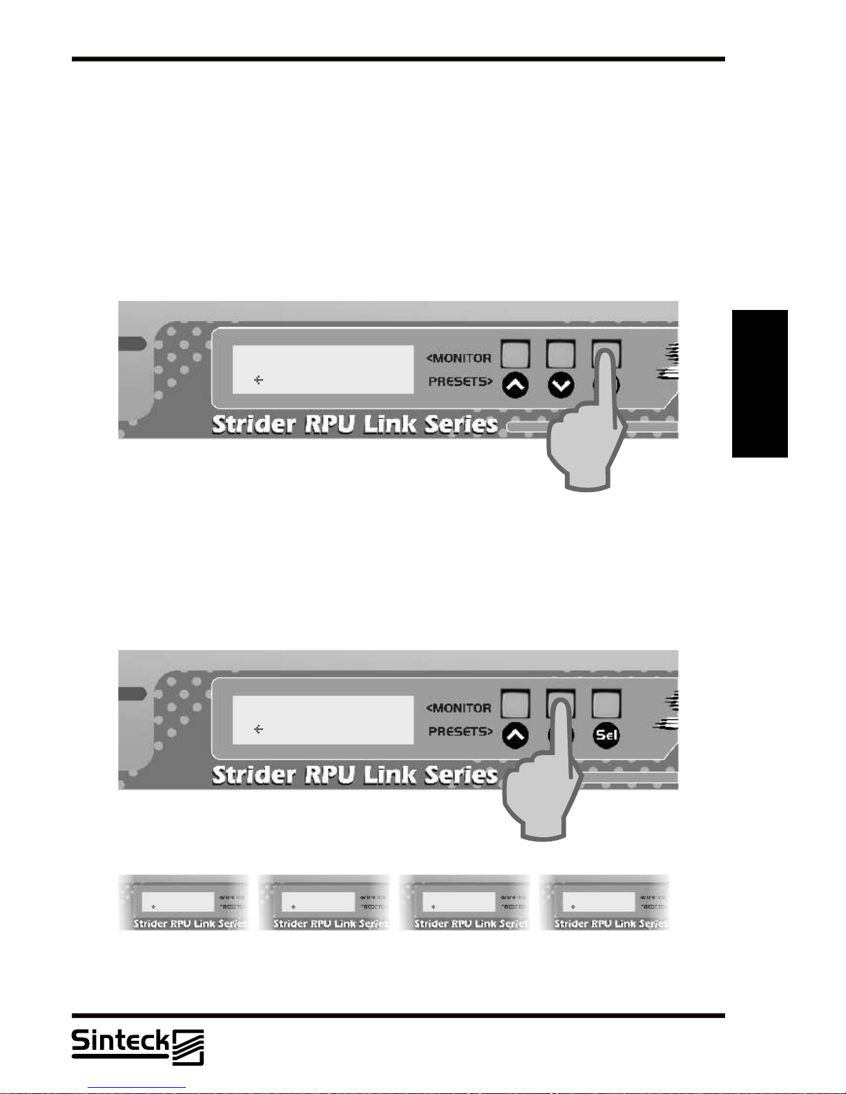
FREQUENCY CHANGING
To change the frequency on the Strider Transmitter Link is necessary to press the
button “UP” or “DOWN”on the front panel, like shows the next figure:
FREQ. 452,50 MHZ
CHANNEL~ 10
FREQ. 452,50 MHZ
CHANNEL~ 10
3
FREQ. 452,75 MHZ
CHANNEL~ 11
FREQ. 452,75 MHZ
CHANNEL~ 11
FREQ. 453,00 MHZ
CHANNEL~ 12
FREQ. 453,00 MHZ
CHANNEL~ 12
FREQ. 453,25 MHZ
CHANNEL~ 13
FREQ. 453,25 MHZ
CHANNEL~ 13
FREQ. 453,75 MHZ
CHANNEL~ 14
FREQ. 453,75 MHZ
CHANNEL~ 14
FREQ. 452,50 MHZ
CHANNEL~ 10
FREQ. 452,50 MHZ
CHANNEL~ 10
3
FREQ. 452,25 MHZ
CHANNEL~ 09
FREQ. 452,25 MHZ
CHANNEL~ 09
FREQ. 452,00 MHZ
CHANNEL~ 08
FREQ. 452,00 MHZ
CHANNEL~ 08
FREQ. 451,75 MHZ
CHANNEL~ 07
FREQ. 451,75 MHZ
CHANNEL~ 07
FREQ. 451,50 MHZ
CHANNEL~ 06
FREQ. 451,50 MHZ
CHANNEL~ 06
3
CONTRAST MENU
To facilitate the LCD view, a Contrast Menu was created. Depending on where is installed
the equipment the user can choose which will be the contrastlevel thatbetter itis adaptedto
the illumination ofthe installation place.
First, the button " SEL " should be pressed, until that the message in LCD is " CONTRAST
ADJUST ". Note that every time that any button is pressed a beep sounds, this is the
feedback that thebutton was worked.
03/P/27
Page 28

3-9 Quick guide for installation and use - Strider Transmitter Link
Strider Link Series
SRFStrider-161004A-REV.A
Sinteck Sistemas Eletrônicos Ltda.
CONTRAST CHANGING
Tochange the contrastlevel onthe Strider Transmitter Link isnecessary to pressthe button
“UP” or “DOWN”onthe front panel,once the message“CONTRASTADJUST”is shown.
CONTRAST ADJUST
LEVEL~ 05
CONTRAST ADJUST
LEVEL~ 05
3
CONTRAST ADJUST
LEVEL~ 05
CONTRAST ADJUST
LEVEL~ 05
CONTRAST ADJUST
LEVEL~ 05
CONTRAST ADJUST
LEVEL~ 05
03/P/28
Page 29
3-10 Quick guide for installation and use - Strider Transmitter Link
Strider Link Series
SRFStrider-161004A-REV.A
Sinteck Sistemas Eletrônicos Ltda.
RF POWER MENU
This view shows tothe user the measurementscorresponding to the power erogation ofthe
Strider Transmitter Link:
1) FowardPower (F): direct powermeasured in percents, 0% corresponds to0W and 100%
corresponds to 8W.
2) Reflected Power (R): reflected power measured in percents, when 0% correspond to 0W
and 100% 8W.
F~ЫЫЫЫЫЫЫЫЫЫЫMAX
R
00%
3
3
ADJUSTING THE RFPOWER
The RF power output of Strider Transmitter Link can be adjusted by the user in steps of
100mW for touch, through the buttons " UP " and " DOWN " is possible to adjust the power
from 0 up to 8W and vice-versa, from 8W to 0W. The following illustrations exemplify this
power adjustment:
F~ЫЫЫЫЫЫЫЫ 80%
R
00%
F~ÛÛÛÛ 40%
R
00%
F~ЫЫЫЫЫЫ 65%
R
00%
F~ÛÛ 25%
R
00%
F~ 00%
R 00%
03/P/29
Page 30
3-11 Quick guide for installation and use - Strider Transmitter Link
Strider Link Series
SRFStrider-161004A-REV.A
Sinteck Sistemas Eletrônicos Ltda.
COMPOSITEAUDIO METER
This view produces to the user the measurements corresponding to the composite signal
which modules theFMOSC in theVCO block ofthe Strider Transmitter Link..
In this section, the modulation level is not configured by the processor. Note that the rear
panel of the Strider Transmitter Link there are 2 direct inputs to theVCO block, that they are:
SCAinput and MPXinput.
When the audio is connected into the each one of those inputs, the deviation must be
adjusted following this Composite Audio Meter. The measure “100%” corresponds to
100kHz of deviationof carrier.
Note that isoften recommended theuser modules upto 75%, abovethis interferences could
be happen inanother channels.
When the Stereo Generatorand Audio ProcessorCard is installed, thismeter never goes to
measure more than75%.
3
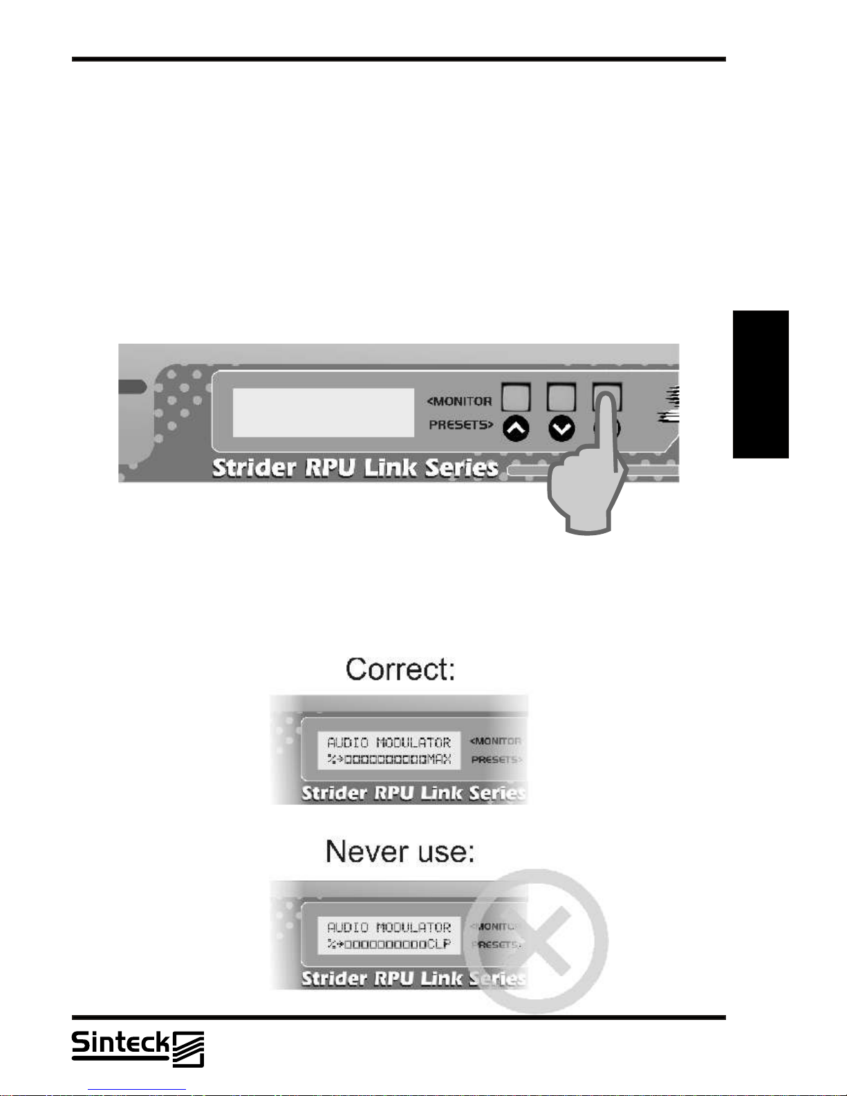
The Strider Transmitter Link support the deviation of 100kHz without any kind of distortion.
“MAX” in theLCD corresponds to110% of modulation,110kHz of deviation.In some case,is
possible totransmit 110% of modulation, but notethat in others channels must nothave any
other users. The “CLP”corresponds to “CLIPPER”.
REMARK: NEVER letthe transmitter modulesmore than “MAX”in any case.
AUDIO MODULATOR
%~ЫЫЫЫЫ
03/P/30
Page 31

3-12 Quick guide for installation and use - Strider Transmitter Link
Strider Link Series
SRFStrider-161004A-REV.A
Sinteck Sistemas Eletrônicos Ltda.
CHANNELS LEFT&RIGHT MENU
ATTENTION: This menu only works when is installed the
STEREO GENERATOR CARD and the “MPX
SELECTION” is selected to “INT” (See this menu in the
next pages).
The input levels of the left and right channels are
represented by vertical bars as indicated in the following
illustration.
The level is measured in percents when 100%
corresponds to adeviation of 100kHzof carrier.
3
The Strider Transmitter Link support the deviation of 100kHz without any kind of distortion.
“MAX” in theLCD corresponds to110% of modulation,110kHz of deviation.In some case,is
possible totransmit 110% of modulation, but notethat in others channels must nothave any
other users. The “CLP”corresponds to “CLIPPER”.
REMARK: NEVER letthe transmitter modulesmore than “MAX”in any case.
L~ЫЫЫЫЫЫЫ
R~ЫЫЫЫЫ
STEREO GENERATOR
INSTALLED
STEREO GENERATOR
INSTALLED
MPX SELECTION
~INT. EXT.
When installed the AUDIO PROCESSOR CARD the maximum modulation will be 75%. If
this card is disabled, then the modulation level can pass of this limit like shows the
illustration.
03/P/31
Page 32
3-13 Quick guide for installation and use - Strider Transmitter Link
Strider Link Series
SRFStrider-161004A-REV.A
Sinteck Sistemas Eletrônicos Ltda.
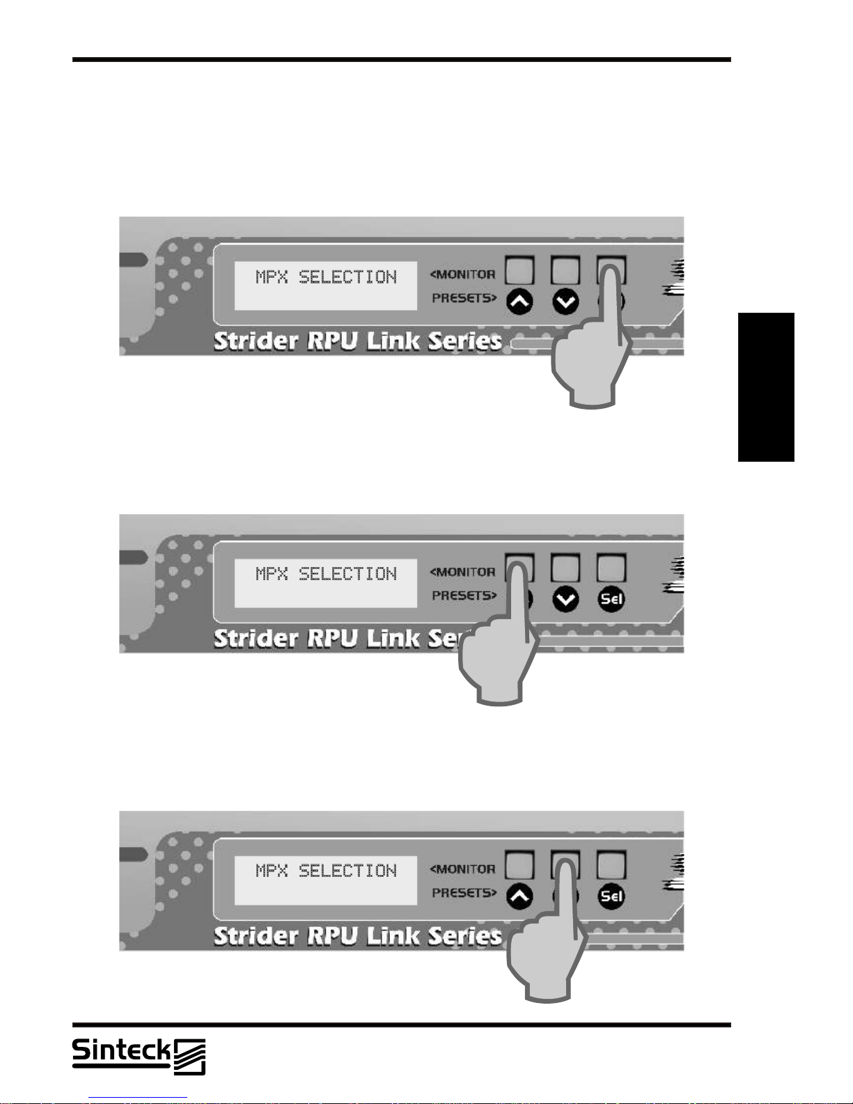
MPX SELECTION MENU
This view produces to the user the option to change the inputs on the Strider Transmitter
Link, only ifthe STEREO GENERATOR CARis installed.
The position “INT” wants to say that the transmitter is working with the INTERNAL MPX
generator,the STEREO GENERATOR CARDis actived.
3
If the case the user wants to change the STEREO to MPX input to put any other kind of
coder, or external stereo generator, the button “UP” must to be pressed, so the input is
changed to MPXexternal and theview will belike the followingillustration:
~INT. EXT.
INT. ~EXT.
To return to the original position or “INT” the button “DOWN” must to be pressed, like the
shown the illustration:
~INT. EXT.
03/P/32
Page 33

3-14 Quick guide for installation and use - Strider Transmitter Link
Strider Link Series
SRFStrider-161004A-REV.A
Sinteck Sistemas Eletrônicos Ltda.
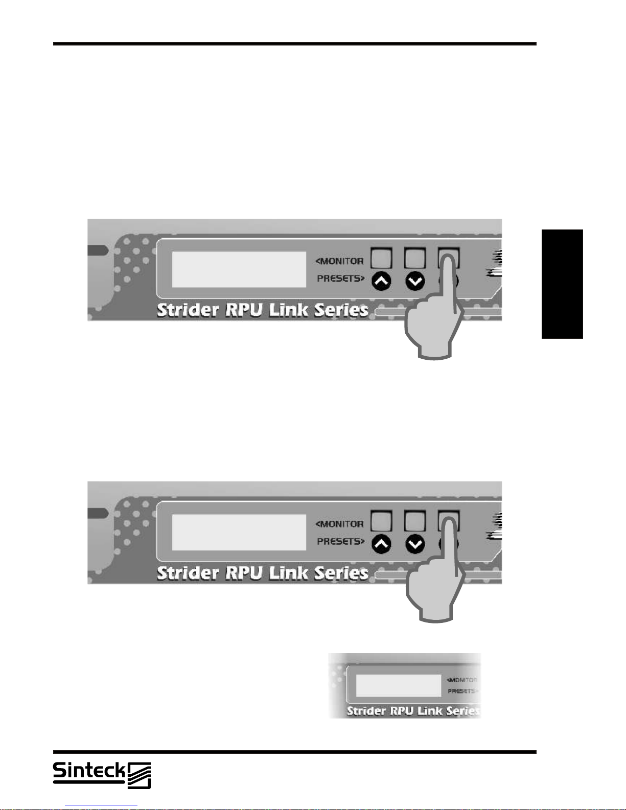
INTERNAL MPX SELECTIONMENU
This view only shows if the STEREO GENERATOR
CARD is installed and the menu MPX SELECTION is
setted to theposition “INT”.
There will be cases that the user will wants to transmit in
MONO although the STEREO GENERATOR CARD is
installed. In thiscase, the transmissionin MONO canbe
possible, just pressing the button " UP " and the
transmitter will transmit in MONO or without pilot tone
19kHz.
3
Note that in the front panel there is 4 Status Leds. The last led corresponds to the Stereo
ON-OFF.Turning the button “UP” and “DOWN” to stereo “ON”or “OFF” this LED indicates if
the Internal MPXis operating ornot, like shownin this illustration:
~STEREO MONO
INTERNAL MPX:
STEREO ~MONO
INTERNAL MPX:
STEREO GENERATOR
INSTALLED
STEREO GENERATOR
INSTALLED
MPX SELECTION
~INT. EXT.
03/P/33
Page 34

3-15 Quick guide for installation and use - Strider Transmitter Link
Strider Link Series
SRFStrider-161004A-REV.A
Sinteck Sistemas Eletrônicos Ltda.
AUDIO PROCESSORCONTROL MENU
This view onlyshows if theAUDIO PROCESSORCARD
is installed and the menu MPX SELECTION is setted to
the position “INT”.
There will be cases that the user will wants to transmit
without limited/processed audio although the AUDIO
PROCESSOR CARD is installed. In this case, the
transmission with the audio processor disabled can be
possible, just pressing the button " UP " and the
transmitter will transmit with any audio limit level. This
funcion was placedfor who wantsto connect otheraudio
processor/limiters external to the Strider Transmitter
Link.
3
To change this function, the button “UP’ must be pressed and the AUDIO PROCESSOR
CARD is bypassed (DISABLE). Note that audio level in this moment is not controlled by the
audio processor and must be accompanied for the user. The previous menu “CHANNELS
LEFT&RIGHT” will toshow non-controlled audiolevel measures.
AUDIO PROCESSOR
INSTALLED
AUDIO PROCESSOR
INSTALLED
MPX SELECTION
~INT. EXT.
AUDIO PROCESSOR:
~ENABLE DISABLE
AUDIO PROCESSOR:
~ENABLE DISABLE
03/P/34
Page 35
3-16 Quick guide for installation and use - Strider Transmitter Link
Strider Link Series
SRFStrider-161004A-REV.A
Sinteck Sistemas Eletrônicos Ltda.
POWERAMPLIFIER STATUSMENU
This view showsto the userthe status ofthe P.Aofthe Strider Transmitter Link.
1) VPA-Voltagepresents in theRF module
2) IPA-Current absorbed forthe RF module
This menu is only to showthe Voltage and Current of the P.A.Any parameter is not adjusted
here. The Voltage and Current will be modified if is setted other value in the menu
“ADJUSTING THE RFPOWER”.
3
CONFIG HOLD MENU
This menu disables to set all adjustables menus. Pressing the button “UP” the equipment
now cannot changechannels, contrast, RFlevel, disable orenable cards.
Also, this view permisses to show the Bias voltage presents on the RF power module. This
value is changedwhen the RFpower output issetted.
VPA: 7,48V
IPA: 2,40A
VPA: 7,48V
IPA: 2,40A
VBIAS: 3,44V
CONFIG HOLD: OFF
VBIAS: 3,44V
CONFIG HOLD: OFF
VBIAS: 3,44V
CONFIG HOLD: ON
VBIAS: 3,44V
CONFIG HOLD: ON
Toreturn to theoriginal position inthe “CONFIG
HOLD” the button“DOWN” must tobe pressed.
REMARK: If the Strider Transmitter Link
doesn’t respond the buttons “UP” and “DOWN”
do verify if the “CONFIG HOLD” is enabled.
This function is most important for who needs a
system that nobody has access to change the
parameters (channels, RFpower,etc.)
03/P/35
Page 36

3-17 Quick guide for installation and use - Strider Transmitter Link
Strider Link Series
SRFStrider-161004A-REV.A
Sinteck Sistemas Eletrônicos Ltda.
ALARM FAILSVIEW
1) PLL Unlocked
This fail can happen in the case that PLL system doesn't reach enough voltage to get lock
the VCO . The principal cause of this fail can be the initial moment when the Strider
Transmitter Link is turned on, in this case, observe that the second led that corresponds to
the “PLLLocked” doesn't light. This fail type can happen in less than 1% of the cases when
the equipment is altered the frequency out of the factory. Coming of it manufactures, the
equipment is adjusted among 1/2 VCC that means that the restraint bow is quite big and this
warning won't surelybe exhibited inany case.
3
This view indicatedare “readings”, andtherefore cannot bemodified.
2) VSWR PROTECTION
The Strider Transmitter Link is equipped with a modern and intelligent circuit to protect it for
any kindof antenna fail. Ifin the case that the antennais disconnected, the transmitterautoprotect itself automaticallyreducing the RFlevel to 0W.
Also, if the coax cable has not good impedance or fail in any connection, simplest the
equipment reduces thepower and worksin fold-back mode.
This circuitry isvery fast, allowingthat the transmitterhas a longlife.
Note that in the front panel exists a led to show if the RF power is operating, in this safety
mode, this ledwill be turnedoff.
This view, like the“PLLUNLOCK” are only“readings”and therefore cannotbe modified.
03/P/36
Page 37

3-18 Quick guide for installation and use - Strider Transmitter Link
Strider Link Series
SRFStrider-161004A-REV.A
Sinteck Sistemas Eletrônicos Ltda.
WORKING 100%
Pressing the button “SEL” after turned on the Strider Transmitter Link is possible to verify if
all menus isworking 100% likeexplained in thissection.
STATUS LEDS:
1- Power “ON”
2- PLL locked “OK”
3- RF powerout “OK”
4- Stereo actived
3
FREQ: 454,25 MHZ
CHANNEL 17
FREQ: 454,25 MHZ
CHANNEL 17
03/P/37
Page 38

3-19 Quick guide for installation and use - Strider Receiver Link
Strider Link Series
SRFStrider-161004A-REV.A
Sinteck Sistemas Eletrônicos Ltda.
STRIDER RECEIVER LINK -QUICK START GUIDE FORINSTALLATION ANDUSE
This chapter contains the necessary instructions for the installation and use of the
equipment Strider Receiver Link. In case some aspects are not totally clear, for instance
when a user is using this equipment for the first time, we advise the new user to read
carefully the entiredescription contained inthis manual.
PREPARATION
Unpack the Strider Receiver and check, before making any operation, that the unit has not
suffered from any mishandling during the transport. In particular check that all the
connectors are inperfect conditions.
Check that thesupply voltage coincideswith the AC voltageavailable.
The input supplyfield is of:
STRIDER RECEIVER LINK: 110V or 220Vswitchable
Check that the switch located in the rear panel of the equipment is in position equivalent to
the available voltage.
Check thatthe switch located in the front panel of theStrider Receiver Link is in the position
“OFF”
The Strider Receiver Link has this switch which interrupts completely the AC supply of the
unit.
Connect the antennainto the RFinput connector.
Connect the AC cableto the corresponding VDE socket.
REMARK: It is essential that the AC network has an accurate grounding system in order to
ensure both thesafety of theusers and thecorrect functioning ofthe unit.
USE
Switch onthe receiver by puttingthe selector on the position “ON”the switch situated onthe
front panel.
The following messagemust be viewed:
3
SINTECK
UHF RECEIVER
SINTECK
UHF RECEIVER
Note that this moment the first LED is turned on, indicating the Strider Receiver link has
all supplies voltages “OK
”
03/P/38
Page 39

3-20 Quick guide for installation and use - Strider Receiver Link
Strider Link Series
SRFStrider-161004A-REV.A
Sinteck Sistemas Eletrônicos Ltda.
3
SINTECK
UHF RECEIVER
SINTECK
UHF RECEIVER
After the first LED was turned on, the second LED that indicates the “ PLL LOCK” will must
be turned on,and the followingmessage will beshown:
The unit is equipped with a LCD display with 2 lines on which several menus are shown. A
general view ofthe menus ofthe unit areshown in theillustration.
On the center of the display, depending on the case, the following symbol will be shown:
~
The parameter indicated can be modified in the menu CHANNEL, CONTRAST, AUDIO
LEVELADJUST,AUDIO MUTE AND CONFIGHOLD.
When the unit is switched on, theLCD display shows the predefined view, with thegraphical
representation of thechannel set andstops there, likethe following sequence:
PLL LOCKED
In this view, the frequency of operation is shown:
FREQ. 452,50 MHZ
CHANNEL~ 10
FREQ. 452,50 MHZ
CHANNEL~ 10
Note that this moment if possible to change the frequency of operation on the Strider
TransmitterLink.
REMARK: Make sure that the antenna can respond to all frequencies of the Strider Link,
that has 5MHz bandwidht at minimum. The Strider Receiver Link has a dual cavity system
with highgain, if the antennais outof the central frequencythe user will note that thelevel of
RF-in is lessthan “MAX” ifthe Strider Transmitter link is operatingnear from thisreceiver.
03/P/39
Page 40

3-21 Quick guide for installation and use - Strider Receiver Link
Strider Link Series
SRFStrider-161004A-REV.A
Sinteck Sistemas Eletrônicos Ltda.
FREQUENCY CHANGING
To change thefrequency on the Strider Receiver Link isnecessary to press thebutton “UP”
or “DOWN”on thefront panel, likeshows the nextfigure:
FREQ. 452,50 MHZ
CHANNEL~ 10
FREQ. 452,50 MHZ
CHANNEL~ 10
3
FREQ. 452,75 MHZ
CHANNEL~ 11
FREQ. 452,75 MHZ
CHANNEL~ 11
FREQ. 453,00 MHZ
CHANNEL~ 12
FREQ. 453,00 MHZ
CHANNEL~ 12
FREQ. 453,25 MHZ
CHANNEL~ 13
FREQ. 453,25 MHZ
CHANNEL~ 13
FREQ. 453,75 MHZ
CHANNEL~ 14
FREQ. 453,75 MHZ
CHANNEL~ 14
FREQ. 452,50 MHZ
CHANNEL~ 10
FREQ. 452,50 MHZ
CHANNEL~ 10
3
FREQ. 452,25 MHZ
CHANNEL~ 09
FREQ. 452,25 MHZ
CHANNEL~ 09
FREQ. 452,00 MHZ
CHANNEL~ 08
FREQ. 452,00 MHZ
CHANNEL~ 08
FREQ. 451,75 MHZ
CHANNEL~ 07
FREQ. 451,75 MHZ
CHANNEL~ 07
FREQ. 451,50 MHZ
CHANNEL~ 06
FREQ. 451,50 MHZ
CHANNEL~ 06
3
CONTRAST MENU
To facilitate the LCD view, a Contrast Menu was created. Depending on where is installed
the equipment the user can choose which will be the contrastlevel thatbetter itis adaptedto
the illumination ofthe installation place.
First, the button " SEL " should be pressed, until that the message in LCD is " CONTRAST
ADJUST ". Note that every time that any button is pressed a beep sounds, this is the
feedback that thebutton was worked.
03/P/40
 Loading...