


SINPRO ENTERPRISE
LM2455-ER/EU/EC SINPRO
Zb MANUAL
(For FCC/CE Certificate)
(Revision 1.0)
1. LM2455-ER(or LM2455-EU or LM2455-EC)
(GENERAL DESCRIPTION)
LM2455-ER(or LM2455-EU or LM2455-EC) is ZigBee RF module. This module includes RF
Transceiver, RF circuit,8051- compatible MCU and few external components such as resistors
and capacitors. In addition, it is compliant to the specification of IEEE802.15.4 and ZigBee
specifications. Zpulse, ZigBee 2006 stack library, provided by RadioPulse Inc is included in this
module. LM2455-ER(or LM2455-EU or LM245 5-EC) module supports data rate from 250Kbps to
1Mbps.
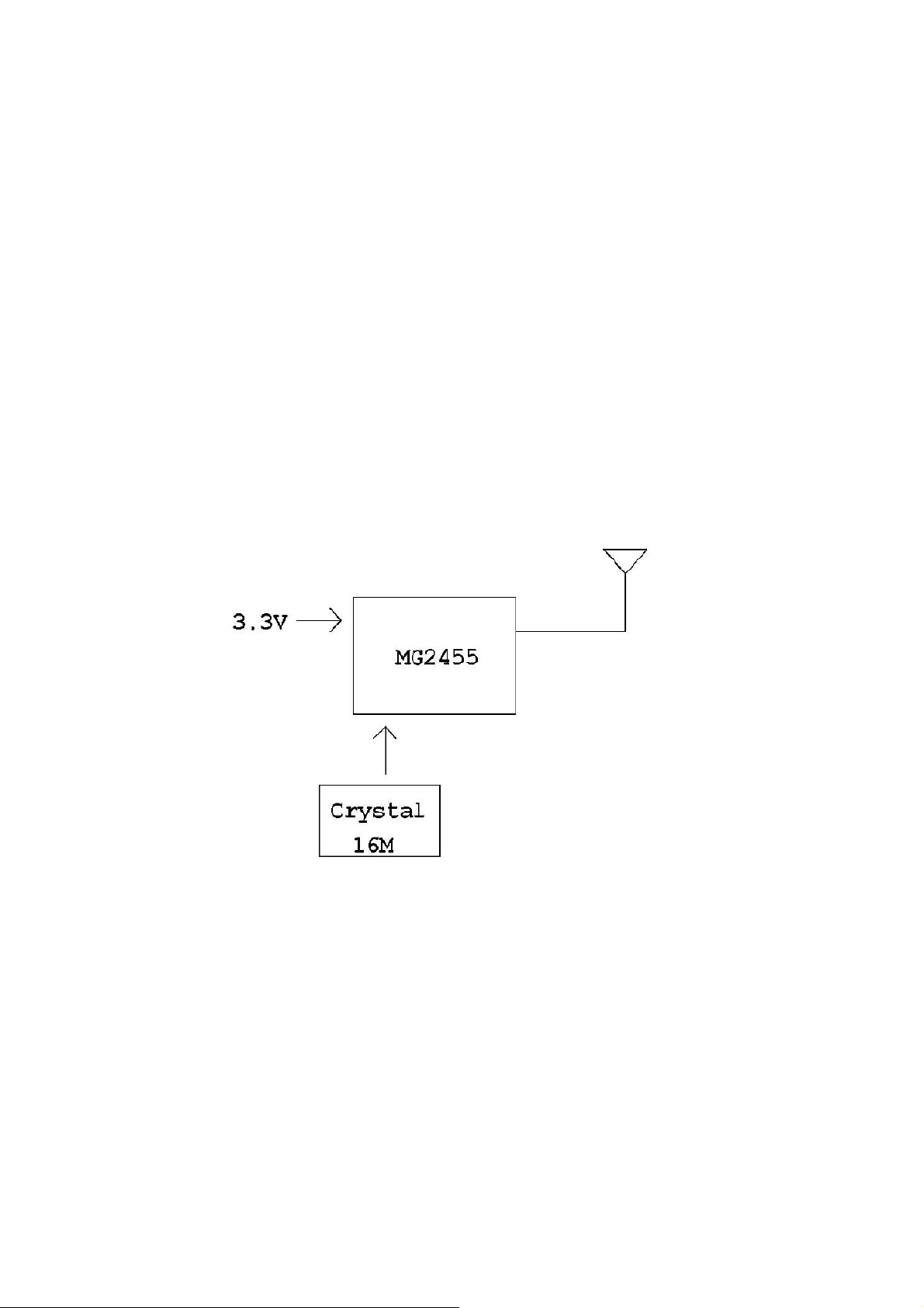
1.1. Block Diagram
As shown in [Figure 1], LM2455-ER(or LM2455-EU or LM2455-EC) includes the following features.
Figure 1.
MG2455-F48
20-Pin
Connector
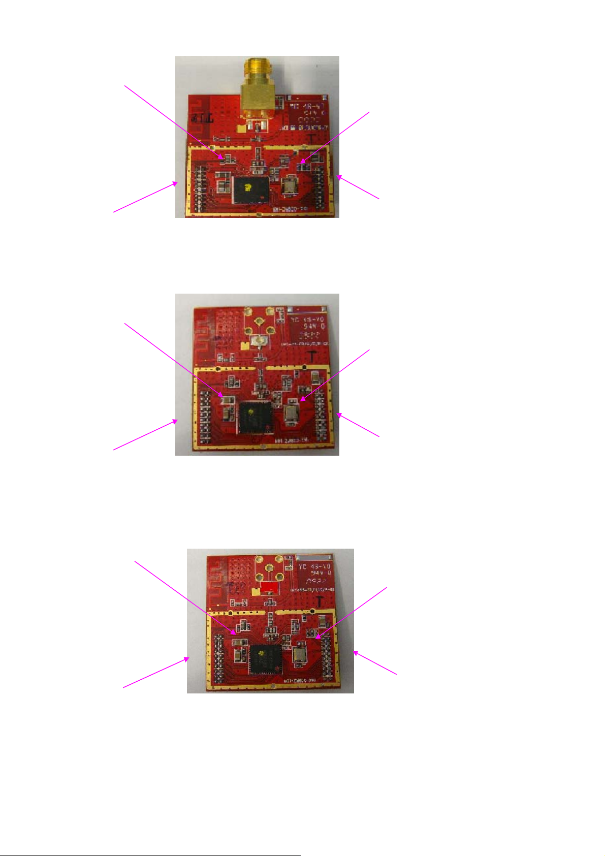
Figure 2. LM2455-ER
MG2455-F48
20-Pin Connector
Figure 3. LM2455-EU
MG2455-F48
20-Pin Connector 20-Pin Connector
4.
Figure
LM2455-EC
16MHz Crystal
20-Pin Connector
16MHz Crystal
20-Pin Connector
16MHz Crystal
2. MG2455-F48 Components
[
]
2.1. Hardware Components
- LM2455-ER(or LM2455-EU or LM2455-EC) : 1 EA
- MG245X-EVB : 1 EA
- USB Cable : 1 EA
- 2dBi Pole Antenna : 1 EA
LM2455-ER(or LM2455-EU or LM2455-EC): MG2455 Installed RF Module
MG245X-EVB : PC Interface EVALUATION Board
2.2. HARDWARE
2.2.1. Hardware Setting and Binding for Test
Figure5. Basic Hardware Setting (Transmit/Receive)
Switch
Two pcs each of Evaluation Board and Evaluation Module provided by
RadioPulse are needed.(transmit, receive)
* EVB: EValuation Board(EVB), EM: Evaluation Module(EM)
Evaluation Board EM
#5,#7 ON
UART1
USB select Normal select
Figure 5. MG245X- EVB
1-2(Local ISP) select
3. Operation
1) After you stick LM2455-ER in MG245X -EVB , connect MG245X-EVB to your
PC using the USB cable as shown below figure.

3.1. SOFTWARE
3.1.1. PC Terminal Program
PC Terminal Program is used for test controlling and monitoring.
A terminal program called ‘Tera-Term Pro’ is introduced in this section.
(This program is a freeware.)
**NOTE: Tera-term Pro supports COM1, COM2, COM3, and COM4 only.
(When revising initial file, it’s possible up to COM16.)
After Tera-Term Pro inst allat ion , f ollow t he procedure below. a.
Set hardware(EM, EVB)
b. Connect pc and EVB with USB cable.
c. Start Tera-Term Pro and open COM port.
Menu bar -> Setup -> Serial port -> Serial port setup Dialogue box
-> Set Port , Baud rate, Data, Parity, Stop and Flow control -> OK
Port: Corresponding COM port(About MS Windows OS, Refer to port item of
device manager.)
Baud rate: 115200
Data: 8 bit
Parity: none
Stop: 1bit
Flow control: none

3.2. How to Use Test Program
3.2.1. Information
In test program, Tx and Rx use same firmware. Tx and Rx are classified by
inputting 0/1 in PC terminal program.
The firmware is MG245X-MTP_V17.H00, MG245X-MTP_V17.H01. For d ow nlo ad
information, refer to Device Programmer User’s Guide.
Test program is divided into Automatic Test and Single Test in general.
Automatic Test can test several items centered on MCU Peripheral at a time.
Single Test tests the single item in case equipment is needed or test time is
uncertain.
*Reference: Test Program’s default setting – Channel: No 22, Output:
Maximum(10dBm)
Detailed test process is as follows;
3.2.1.1
After connecting PC and Evaluation Board, follow the process below.
Figure6. Hardware setting for Automatic Test
Automatic Test Practice
Confidential
EVB&EM1(Tx)
PC1 USB cable
RF
communication
PC2 USB cable EVB&EM2(Rx)

Evaluation Board
8001: Input
Switch
a. Set ISP switch to Normal mode.(EVB operating)
b. Press RESET button.(EVB operating)
#5,#7 ON
Confidential
–Press RESET butt on when it ’s stick to certain test mode or simple mistake
ⓐ Normal Select
occurs.
c. When a message as below is shown in program window of PC terminal, set
same Mode with DUT after press 0(zero) for Station(Rx).
For DUT(Device Under Test), Select a status of testing subject.
When testing subject is MG2455 module, (Refer to figure below.)
Receive module(Rx on Figure3): 0 Input 3 Input
Transmit module(Tx on Figure3): 3 Input. (DUT: Module for
test)
Transmit/Receive setting is needed for Automatic Test RF Tx-Rx testing item.

d. When testing item is selected, Device Information and Help Message
Figure7. Start Program
are shown. There are several test items in Help Message. When a user press
‘0’, testing item selected basically is processed automatically. (Refer to
Automatic Test.)
Rx Station
Press RESET
0:lnput
Device lnformation
3:lnput
Help
Confidential

Confidential
Press RESET
Device Information
3 : Input
Help
Tx DUT

Confidential
Automatic Test result
when ‘ 0’ input
System reset with
WATCHDOG-TIMER test
Tx DUT

Federal Communication Commission Interference Statement
This equipment has been tested and found to comply with the limits for a Class B digital
device, pursuant to Part 15 of the FCC Rules. These limits are designed to provide
reasonable protection against harmful interference in a residential installation. This
equipment generates, uses and can radiate radio frequency energy and, if not installed
and used in accordance with the instructions, may cause harmful interference to radio
communications. However, there is no guarantee that interference will not occur in a
particular installation. If this equipment does cause harmful interference to radio or
television reception, which can be determined by turning the equipment off and on, the
user is encouraged to try to correct the interference by one of the following measures:
● Reorient or relocate the receiving antenna.
● Increase the separation between the equipment and receiver.
● Connect the equipment into an outlet on a circuit different from that to which the
receiver is connected.
● Consult the dealer or an experienced radio/TV technician for help.
FCC Caution: Any changes or modifications not expressly approved by the party
responsible for compliance could void the user’s authority to operate this equipment.
This device complies with Part 15 of the FCC Rules. Operation is subject to the following
two conditions: (1) This device may not cause harmful interference, and (2) this device
must accept any interference received, including interference that may cause undesired
operation.
This device and its antenna(s) must not be co-located or operation in conjunction with
any other antenna or transmitter.
Confidential

IMPORTANT NOTE:
This module is intended for OEM integrator. The OEM integrator is still responsible for
the FCC compliance requirement of the end product, which integrates this module.
Any changes or modifications not expressly approved by the manufacturer could void
the user's authority to operate this equipment.
USERS MANUAL OF THE END PRODUCT:
The end user has to be informed that the FCC radio-frequency exposure guidelines for
an uncontrolled environment can be satisfied. The end user has to also be informed
that any changes or modifications not expressly approved by the manufacturer could
void the user's authority to operate this equipment. If the size of the end product is
smaller than 8x10cm, then additional FCC part 15.19 statement is required to be
available in the users manual: This device complies with Part 15 of FCC rules.
Operation is subject to the following two conditions: (1) this device may not cause
harmful interference and (2) this device must accept any interference received,
including interference that may cause undesired operation.
LABEL OF THE END PRODUCT:
The final end product must be labeled in a visible area with the following " Contains TX
FCC ID: XBJLM2455ER-EU-EC ". If the size of the end product is larger than 8x10cm,
then the following FCC part 15.19 statement has to also be available on the label: This
device complies with Part 15 of FCC rules. Operation is subject to the following two
conditions: (1) this device may not cause harmful interference and (2) this device
must accept any interference received, including interference that may cause
undesired operation.
Confidential
 Loading...