

Sinovo SP200-2S-0.7, SP200-4T-3.7, SP200-4T-2.2, SP200-2S-2.2, SP200-4T-5.5 User Manual
...Page 1

SP200 Drive User Manual (Version: 2.0)
SP200 SERIES
PV PUMP CONTROLLER
User Manual
SHENZHEN SINOVO ELECTRIC TECHNOLOGY CO.,LTD
Add: 5 th Floo r,No. D Build ing,H uafen g Inter natio nal Rob ot
Indu stry Pa rk,Xi xiang S treet ,Hang cheng R oad,B aoan
Dist rict, Shenz hen Cit y
Tel 0755 2978 4870: ( )
F 0755 2978 4969ax: ( )
Tech s uppor : 400-88 1-868 9
http : //www .sino vo.cn
Version: 2.0
Page 2

SP200 Manual
Preface
Preface
Thank you for purchasing the SP200 series PV Pump controller developed by our
company.
This manual introduce how to use SP200 series in correct manner. Please read it carefully
before application, operation, maintenance and inspection.
Please apply this series after fully understand the safety cautions of this products.
Unpacking Inspection Cautions:
1.Whether the product is damaged during shipping, whether the parts is damaging or
falling, whether the main part is crashed.
2.Whether the nameplate of model and controller ratings are consistent with your order.
SINOVO is very strict in quality control in the producing and packing, in case any fault
occcurs, please contact us or your own supplier ASAP.
Note
For the details of illustrating products, the diagram of this manual is sometimes in the
ª
status of removing the cover or safety cover. To use this product, please make sure
install the cover or housing as required and operate in accordance with manual
instructions.
The diagrams in this manual is only for illustration, it may have sightly difference with
ª
the product that you ordered.
This instructions are subject to change, without notice, due to product upgrade,
ª
specification as well as efforts to increase the accuracy and convenience of the
manual.
Please contact district agent or all SINOVO customer service center directly for the
ª
damaged or missing parts and need to order the Manuals.
If you have any confusion when refering the manual during operation, please contact
ª
SINOVO Customer Service Center.
Customer Service: 400-8818-689
ª
-1 -
Page 3

Contents
SP200 Manual
Contents
Preface.................................................................................................................01
Contents...............................................................................................................02
Chapter 1 Safety and Cautions..........................................................................05
Safety Definition.....................................................................................................05
1.1 Safety Cautions................................................................................................06
1.2 Cautions.... ................................................................................................08.......
Chapter 2 Basic principle...................................................................................11
2.1 Basic principle.... ............................................. ........... ....
2.2 Functions.................................................................................... .
Chapter 3 Product Information.........................................................................15
3.1 Inspection... .. ............................................................................. ......... ...... ...... 16
3.2 Instroductions and Feature....... ..................................................... ...... ........... 16
3.3 Protection function..... .......................................................................... ....... .... 16
3.4 Naming rules............... ................................................................................... .17
3.5 SP200 PV Pump Controller input/output parameter................. ......... ............. . 17
3.6 Nameplate...................... ........................................................... ..................... . 21
3.7 SP200 PV pump controller Size....... .... .......................................................... . 21
............. . ...................
....................
11
13
Chapter 4 Mechanical and Electrical Installation.............................................25
4.1 Controller Installation and Operation Environment........ ..............................26....
4.2 Controller Installation Spacing............ ............................................ ...........27.. ...
4.3 Install and Remove the Cover........ .......................................... ..............27....... ..
4.4 Wiring......................... .... .....................................28...................................... ......
Chapter 5 Operation..........................................................................................35
5.1 Operation Panel Description... .................. .......................................36 .. .............
5.2 Operation Procedure............ ............ ...................38 ........ ....................................
5.3 Commissioning Process..................................................................................40
5.4 Panel Displays Parameters in Running State.................. ... ...................40....... ..
-2 -
Page 4

SP200 Manual
Contents
Chapter 6 Function Parameter Table...............................................................41
F00 Basic Function Group.................... ........................ .............................42........... ..
F01 Startup and Stop Control........ .............................................................42............
F02 Motor parameter............... ......... .............. ..................................................... .. . 42
F03 Solar Water Pump Special Parameters... ....................................... .... ........ ... .. 42
F05 Input Terminal Group................. ........................... . ............... ......................... .. 43
F07 HMI&Fault parameters....................................................................................43
Chapter 7 Troubleshooting...............................................................................47
7.1 Fault Instruction and Solution..................................................... . .........48.......... .
7.2 Common Faults and Solutions......................................................... .......51.........
7.3 Controller Overcurrent, Overload Fault (OC1/2/3/OL1/2)................................52
Chapter 8 Maintenance.....................................................................................53
8.1 Controller........ ........................... . .........54............................. .............................. .
8.2 Pump.............. .............................................. .......56................................... .........
8.3 Solar Array.......................................................................................................56
8.2 Electric Wire and Cable..................................................................................56
Chapter 9 Spare AC power use........................................................................57
-3 -
Page 5

-4 -
Page 6

Chapter 1
Safety and Cautions
Safety Definition
Read this manual carefully so that you have a thorough understanding.
Installation,commissioning or maintenance may be performed in conjunction with this
chapter. Our company will assume no ability and responsibility for any injury or loss caused
by improper operation.
Danger
Operations which are not performed comply with the requirements may cause severe hurt
or even death.
Note
Operations which are not performed comply with requirements may cause personal injury
or property damage.
-5 -
Page 7
Chapter1 Safety and cautions
1.1 Safety Cautions
SP200 Manual
Use Stage Safety Grade
Danger
Before
Installation
Danger
Danger
During
Installation
Note
At wiring
Danger
Precautions
Do not install the equipment if you find water seepage,
ª
component missing or damage upon unpacking.
Do not install the equipment if the packing list does not
ª
conform to the product you received.
Handle the equipment with care during transportation to
ª
prevent damage to the equipment.
Do not use the equipment if any component is damaged or
ª
missing. Failure to comply will result in personal injury.
Do not touch the components with your hands. Failure to
ª
comply will result in static electricity damage.
Install the equipment on incombustible objects such as
ª
metal, and keep it away from combustible materials.
Failures to comply may result in a fire.
Do not loosen the fixed screws of the components,
ª
especially the screws withe red marks.
Do not drop wire end or screw into the controller. Failure it
ª
will result in damage to the controller.
Install the controller in places free of vibration and direct
ª
sunlight.
When two controller are laid in the same cabinet ,arrange the
ª
installation positions properly to ensure the cooling effect.
A circuit breaker must be used to isolate the power supply
ª
and the controller. Failure to comply may result a fire.
Ensure that the power supply is cut off before wiring. Failure
ª
to comply may result in electric shock.
Never connect the power cables to the output
ª
terminals(U,V,W) of the controller. Pay attention to the
marks of the wiring terminals and ensure correct wiring.
Failure to comply may result in damage to the controller.
Ensure that the main cable line comply with the standard,
ª
the line meets the EMC requirements and the area safety
standard. Failure to comply may result in risk or accident.
Never connect the power cables the braking resistor
ª
between the DC bus terminals P+, P-. Failure to comply
may result in a fire.
-6 -
Page 8
SP200 Manual
Chapter1 Safety and cautions
Use Stage Safety Grade
At wiring
Before
Power-on
After
Power-on
Danger
Danger
Danger
Danger
During
Operation
Danger
Precautions
Use a shielded cable for the encoder, and ensure that the
ª
shielding layer is reliably grounded.
Please confirm the peripheral equipment and cable converter
ª
is configured in this manual of the recommended model, all
the configuration line in accordance with the connection
method of the manual provides the correct wiring. Failure to
comply will result in accidents.
Check that the voltage class of the power supply is consistent
ª
with the rated voltage class of the controller.
Do not open the controller’s cover after power-on. Failure to
ª
comply may result in electric shock.
Do not touch the operation of controller during the hands is
ª
wet. Failure to comply will result in accident.
Do not touch any I/O terminal of the controller. Failure to
ª
comply may result in electric shock.
Do not change the default settings of the controller. Failure to
ª
comply will result in damage to the controller.
Do not touch the rotating part of the motor during the motor
ª
auto-tuning or running. Failure to comply will result in
accident.
Signal detection must be performed only by qualified
ª
personnel during operation. Failure to comply will result in
personal injury or damage to the controller.
Do not touch the fan or the discharging resistor to check the
ª
temperature. Failure to comply will result in personal burnt.
Avoid objects falling into the controller when it is running.
ª
Failure to comply will result in damage to the controller.
Do not start or stop the controller by turning the contactor
ª
ON/OFF. Failure to comply will result in damage to the
controller.
After
Power-on
Danger
Do not repair or maintain the controller at power-on. Failure
ª
to comply will result in electric shock.
Ensure that the controller is disconnected from all power
ª
suppliers before staring repair or maintenance on the
controller.
Repair or maintenance of the controller may be performed
ª
only by qualified personnel. Failure to comply will result in
personal injury or damage to the controller.
-7 -
Page 9

Chapter1 Safety and cautions
SP200 Manual
Use Stage Safety Grade
After
Power-on
Danger
Set and check the parameters again after the controller is
ª
replaced.
Precautions
1.2 Cautions
1.2.1 Motor Insulation Test
Perform the insulation test when the motor is used for the first time, or when it is reused
after being stored for a long time, or in a regular check-up, in order to prevent the poor
insulation of motor windings from damaging the controller during the insulation test. A 500V mega-Ohm meter is recommended for the test. The insulation resistance must not be
less than 5 MΩ.
1.2.2 Thermal Protection of Motort
If the selected controller does not match the rated capacity of the motor , especially when
the rated power of the controller is higher than that of the motor, adjust the parameters for
motor protection in the controller or to install thermal relay to protect the motor .
1.2.3 Running Above Rated Frequency
The controller provides frequency output of 0 to 600.00Hz. If the controller is required to
run at over 50Hz, please consider the capacity of the machine.
1.2.4 Vibration of mechanical device
The controller may encounter the mechanical resonance point at some output frequenc-ies,
which can be avoided by setting the skip frequency. If the operating frequency of the
customer coincide with the resonant frequency please modify the operating frequency or
change the inherent resonance frequency of the mechanical system.
1.2.5 Motor heat and noise
The output of the controller is pulse width modulation (PWM) wave with certain harmonic
frequencies, and therefore, the motor temperature, noise, and vibration are slightly greater
than those when the controller runs at power frequency (50 Hz).
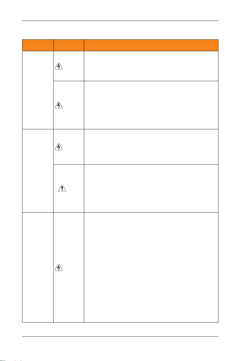
1.2.6 Voltage-sensitive device or capacitor on output side of the controller
Do not install the capacitor for improving power factor or lightning protection voltagesensitive resistor on the output side of the controller because the output of the controller is
PWM wave. Otherwise, the controller may suffer transient overcurrent or even
bedamaged.
-8 -
Page 10
SP200 Manual
SP200
controller
W
U V
Capacitor or
voltage-sensitive resistor
M
1.2.7 Contactor at the I/O terminal of the controller
When a contactor is installed between the input side of the controller and the power supply,
the controller must not be started or stopped by switching the contactor on or off. If the
controller has to be operated by the contactor, ensure that the time interval between
switching is at least one hour since frequent charge and discharge will shorten the service
life of the capacitor inside the controller.
When a contactor is installed between the output side of the controller and the motor,do not
turn off the contactor when the controller is active. Otherwise, modules inside the controller
may be damaged.
1.2.8 The Use Occasion of the External Voltage Out of Rated Voltage Rage
The controller must not be used outside the allowable voltage range specified in this
manual. Otherwise, the controller’s components may be damaged. If required, use a
corresponding voltage step[-up or step-down device.
Chapter1 Safety and cautions
1.2.9 Change Three Phase Input into Two Phase Input
It is not allowed to change the three phase controller into two phase one . Otherwise , it
may cause it may cause fault or damage the controller.
1.2.10 The Protection of the Lighting Impulse
Although the controller has equipped with lightning overvoltage, overcurrent device, which
has a certain protection function for the induction lightining. For the lightning prone areas,
the user is necessary to install lightning protection device at the front of the controller,
which will benefit to the service life of the transducer.
1.2.11 Altitude and Derating
In places where the altitude is above 1000m and the cooling effect reduces due to thin airit
is necessary to de-rate the controller. Contact Our company for technical support.
-9 -
Page 11

Chapter1 Safety and cautions
SP200 Manual
1.2.12 Some Special Usages
If writing that is not described in this manual, such as common DC bus is applied, contact the agent or Our company for technical support.
1.2.13 The Cautious of the controller Disposal
The electrolytic capacitors on the main circuits and PCB may explore when they are burnt.
Poisonous gas is generated when the plastic parts are burn. Treat them as ordinary indu-
strial refer to relevant national laws and regulations.
1.2.14 Adaptable Motor
1. The standard parameters of the adaptable motor is adaptable four-squirrel-cage
asynchronous induction motor or PMSM. For other types of motor, select a proper
controller according to the rated motor current.
2. The cooling fan and rotor shaft of general controller are coaxial, which results in reduced
cooling effect when the rotational speed declines. If variable speed is required, add a
more powerful fan or replace.
3. The standard parameters of the adaptable motor have been configured inside the
controller. It is still necessary to perform motor auto-tuning or modify the default values
based on actual conditions. Otherwise, the running result and protection performance
will be affected.
4. The controller may alarm or even be damaged when short-circuit exists on cables or
inside the motor. Therefore, perform insulation short-circuit test when the motor and
cables are newly installed or during routine maintenance. During the test, make sure
that the controller is disconnected from the tested parts.
-1 0-
Page 12

Chapter 2
Basic principle
2.1 Basic principle
SP 200 solar pumping system can provide water for remote areas lacking of electricity or
places where the electricity supply is unstable. PV pump controller can convert the DC
power from solar panels to AC power so to drive various kinds of pumps.System enables
continiously pumping when in good weather. System is not equipped with strorage battery
devices, it is suggested that pumping the water to conservation pool for future use.Water
source could come from river, lake,well,or other natural water source or special
soucre.System enables application of floating switch in the conservation pool or water
tower to control the operation of pumps. Low water level probes can be installed in the
well to detect the water level of the well in order to stop the pumps when the well in low
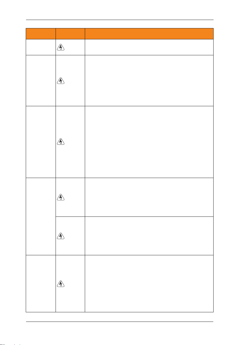
water level. Diagram 1 is a typical SP200 PV pumping system. The main parts and
compenents of this system is after diagram 1.
-11 -
Page 13
Chapter2 Basic principle
SP200 Manual
C.SP200 PV pump controller
F.Storage tank
A.solar panels
B.DC circuit braker
E. well water
level switch
2-1 SP200 PV pumping system
D.pump
SP200 PV pumping system is composed of following parts:
A: Solar panels
:
B DC circuit braker or disconnector
:
C SP200 PV pump controller
:
D Pump
:
E well water level switch(optional)
:
F water tower water level switch(optional)
P
S 200 PV pump controller can start the pump softly and is consistent with the electricity
coming from the changes providing by solar panels. The advantage of soft starting is avoid
surge or power surges when the pump or motor are in the process of starting,whi-ch
reduce the loss of motor and pumping system.
Requirements of pump check valve:
Note: To ensure the best reliability of the system and water supply, check valves is required
to be installed in the output pipe. The first check valves must be installed in the outlet of
pumps, the rest check valves should be installed in the vertical direction of the pipes of
every 30 meters(100 feet) behind the pump.
-1 2-
Page 14

SP200 Manual
Chapter2 Basic principle
2.2 Functions
System diagnostics
SP200 PV pump controller continuously monitor the system performance and can detect a
variety of abnormal circumstance. In most cases, controller provide compensations as
required to keep the non-stop operation of the system. If there is a damage, controller will
protect the system and display fault state. If possible, controller will restart after the fault
status is gone. Fault codes and correction information please refer to the chapter of
Detecting and troubleshooting.
Motor soft-starter
Generally speaking, S 200pv pump controller will operate when there is water requirement or electricity is available.Everytime SP200 PV Pump Controller detect the water
requirement, the rotating speed is always improved slowly and at the same time add motor
voltage gradually.Compared to traditional water supply system, solar pumping sytem's
motor temperature and starting current is much lower. Controller with soft starting function
has no damage to the motor.
Overheating monitoring
P
S 200 PV pump controller can run at full power when the ambient temperature reaches
45℃ For temperature above 45℃, controller will keep on running by reducing output
power. When the controller temperature cooled to safety point, it will run at full power
output.
P
Water level float switch
P
S 200 PV pump controller can connect 2 water level detecting switch to detect pump
running by remote control. Water level switch is optional to the controller, it is not required.
SP200 PV pump controller's input power terminals can be switched to spare AC power
supply manually.
Spare AC power supply switch
Note: Based on different models, SP200 input power could be 220v AC single power, or
380V AC 3 phase power. For more information, please contact SINOVO or certified agent.
When the system is running by spare AC power, please check the DC power every 30 mins.
If the AC power is applicable, then stop the controller and switch to the AC power and try to
run the pump at the AC power driving way.
-1 3-
Page 15

Chapter2 Basic principle
SP200 Manual
Note:
DC circuit switching and generator power switch installation are required and both switches
should be mutually locked to prevent they were connected at the same time which lead to
the solar panels and generator connect SP200 controller simultaneously. Please check if
the design meets electrical specifications of relative country and area.
-1 4-
Page 16

Chapter 3
Product Information
200 PV pump controller is adjustable speed motor controller designed in accordance
SP
with any IEC standard 3 phase asynchronous motor。 SP200 PV pumping system convert
the high voltage DC power of solar array into AC power to drive an standard 3 phase
asynchronous motor thus provide water for remote areas. When the solar power is not
enough, controller can be switched manually to spare single or 3 phase AC power, such as
generator. This controller is functioned with fault detection, motor soft-starting, and speed
control.SP200 PV Pump Controller is designed with the function of plug-and-play and easy
to install.SP200 PV Pump Controller is a product of stable performance and high standard.
In weak light condition, controller will try to drive pump for water lifting, but if the light is
becoming weaker, then controller will reduce the speed of pump to protect the system
components from damaged and shut down during some extreme circumanstances.When
the special circumanstances is gone, controller will restart driving the pump.
-1 5-
Page 17

Chapter3 Product Information
SP200 Manual
3.1 Inspection
Before using, please check the SP200 PV pump controller components firstly. Please make
sure the components serial number is correct and if the product is damaged during
shipping.
3.2 Instroductions and Feature
SP200 PV Pump Controller monitor the system performance continiously and with
integrated protection of multi-function pump system. When fault occurs, SP200 PV Pump
Controller will display the type of faults by LED screen in the front of the controller and will
automatically reset routine fault.
Internal Diagnostics allows lower input voltage.
Whenever possible, the controller will maximize the use of the solar array output to drive
the pump.
To provide users with an easy interface, enhanced configurability and realize remote
monitoring system.
3.3 Protection Function
Electronic monitoring enables the controller to monitor systems and automaticlly shut down
in following circumanstances:
1. Wells is short of water- Low liquild level swtiches;
2. Pump locked rotor overload protection;
3. High voltage surge;
4. Low output voltage;
5. Motor lack phase;
6. Short circuit;
7. Over heating.
Note:
the controller protect the motor by limiting load running when the motor current exceeds the
rated current at the time of low water leve.The controller does not provide high motor
temperature detection.
-1 6-
Page 18
SP200 Manual
Chapter3 Product Information
3.4 Naming Rules
In the model code contains the product information Users can find the code from the
transducerand simple nameplate.
SP
Field Mark
controller series
Series number
Voltage Level
voltage range
Pump rated power
200
1
1
2
3
4
5
2
Solar water pump controller
Series second generation
2: Three-phase 220V
4 Three-phase 380V:
S Rated voltage310VDC,Recommended voltage range
(MTTP)180VDC~360VDC
T: : Rated voltage540VDC,Recommended voltage range
(MTTP)500VDC~600VDC
2.2: 2.2KW
Figure 3-1 Name Designation Rules
-
4
3
Content
T
4
2.2
5
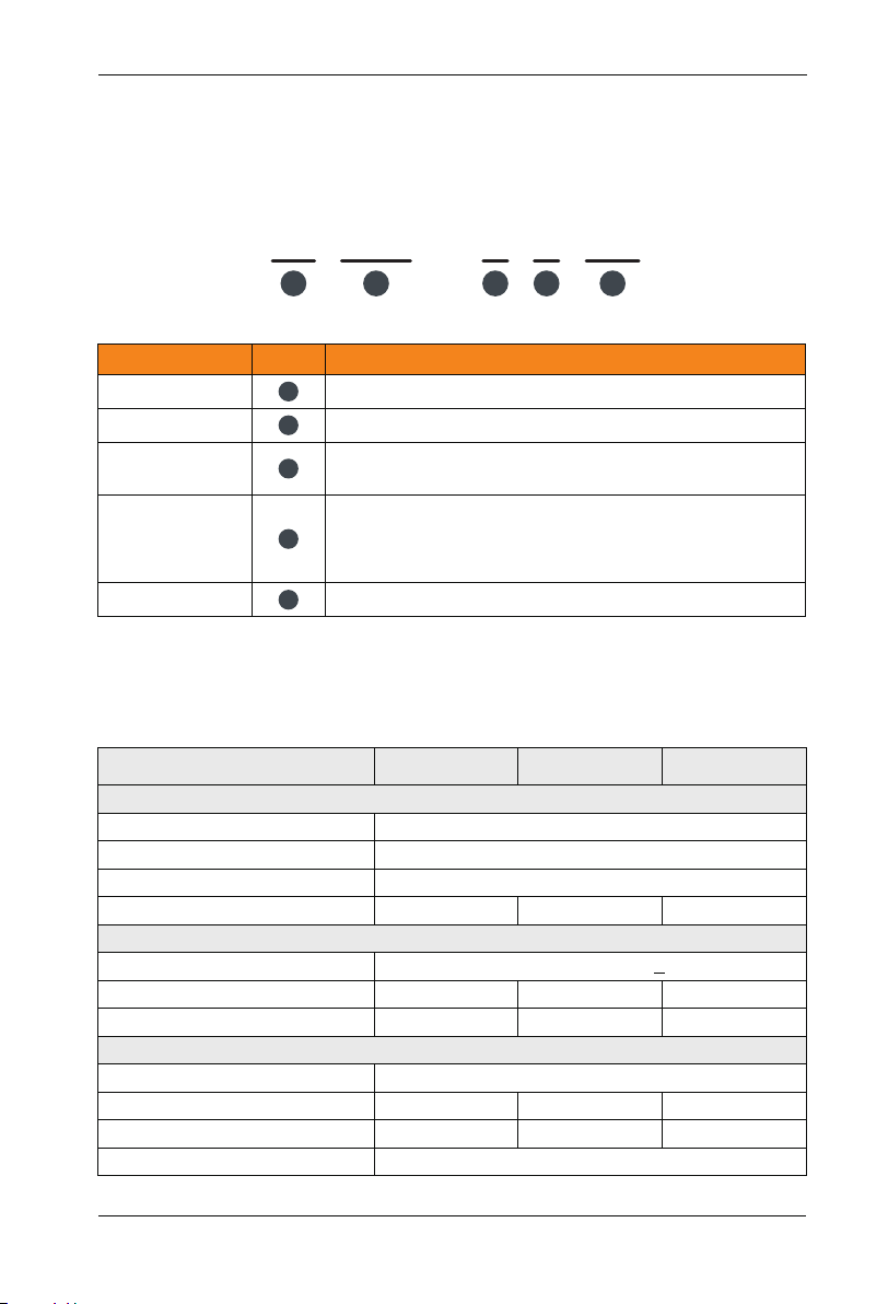
3.5 SP200 PV Pump Controller input/output parameter
SP200-2SXXX
Model
PV array input parameter
Max voltage V ( )input
Min input voltage V ( )
Recommended voltage mpp)(
Recommended PV power(Kw)
Input voltage(V)
Max current A ( )
Generator capacity kVA ( )
Rated output voltage
Max current A( )
Rated output power kW( )
Output frequency
0.9 1.2~
Spare AC generator
Singel phase AC 200-240(+10%)
8.2
1.5
Output parameter
4.7
0.75
DC 450V
DC 180V
DC 280~360V
1.8~2.4
14
3
3-phase AC 200-240V
7.5
1.5
0~50Hz/60Hz
SP200-2S-2.2SP200-2S-0.7 SP200-2S-1.5
2.7 3.5~
23
4
10
2.2
-1 7-
Page 19
Chapter3 Product Information
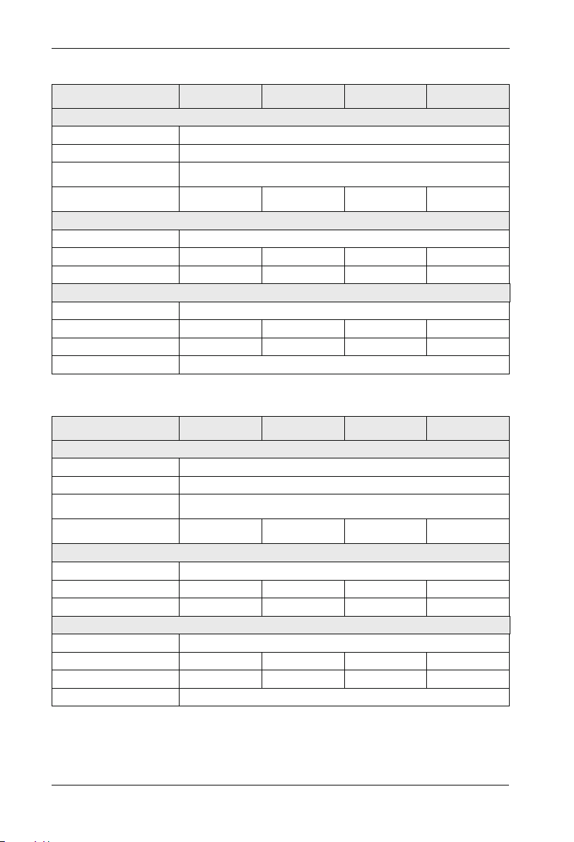
SP200-4TXXX Input/output parameter
Model
PV array input parameter
Max voltage V ( )input
Min input voltage V ( )
Recommended
voltage(mpp)
Recommended
PV power(Kw)
Input voltage(V)
Max current A ( )
Generator capacity kVA ( )
Rated output voltage
Max current A( )
Rated output power kW( )
Output frequency
2.7 3.5~
Spare AC generator
5.8
4
Output parameter
5.1
2.2
SP200-4T-5.5SP200-4T-2.2 SP200-4T-3.7
DC 800V
DC 350V
DC 500~600V
4.8~6.4
3-phase AC 380/400/415/440V(+15%)
10.5
5.9
3-phase AC 380/400/415/440V(+15%)
9
3.7
0~50Hz/60Hz
6.6~8.8
14.6
8.9
13
5.5
SP200 Manual
SP200-4T-7.5
9~12
20.5
11
17
7.5
Model
Max voltage V ( )input
Min input voltage V ( )
Recommended
voltage(mpp)
Recommended
PV power(Kw)
Input voltage(V)
Max current A ( )
Generator capacity kVA ( )
Rated output voltage
Max current A( )
Rated output power kW( )
Output frequency
PV array input parameter
13.2~17.6
Spare AC generator
3-phase AC 380/400/415/440V(+15%)
26
17
Output parameter
3-phase AC 380/400/415/440V(+15%)
25
11
-1 8-
DC 500~600V
18~24
35
21
32
15
0~50Hz/60Hz
SP200-4T-18.5SP200-4T-11 SP200-4T-15
DC 800V
DC 350V
22.2~29.6
38.5
24
37
18.5
SP200-4T-22
26.4~35.2
46.5
30
45
22
Page 20

SP200 Manual
Chapter3 Product Information
Model
Max voltage V ( )input
Min input voltage V ( )
Recommended
voltage( mpp)
Recommended
PV power(Kw)
Input voltage(V)
Max current A ( )
Generator capacity kVA ( )
Rated output voltage
Max current A( )
Rated output power kW( )
Output frequency
Model
Max voltage V ( )input
Min input voltage V ( )
Recommended
voltage( mpp)
Recommended
PV power(Kw)
Input voltage(V)
Max current A ( )
Generator capacity kVA ( )
Rated output voltage
Max current A( )
Rated output power kW( )
Output frequency
PV array input parameter
36~48
Spare AC generator
62
40
Output parameter
60
30
PV array input parameter
90~120
Spare AC generator
157
114
Output parameter
150
75
44~59.2
3-phase AC 380/400/415/440V(+15%)
3-phase AC 380/400/415/440V(+15%)
44~59.2
3-phase AC 380/400/415/440V(+15%)
3-phase AC 380/400/415/440V(+15%)
DC 800V
DC 350V
DC 500~600V
76
57
75
37
0~50Hz/60Hz
DC 800V
DC 350V
DC 500~600V
180
134
176
90
0~50Hz/60Hz
SP200-4T-45SP200-4T-30 SP200-4T-37
SP200-4T-110SP200-4T-75 SP200-4T-90
54~72
92
69
91
45
132~176
214
160
210
110
SP200-4T-55
66~88
113
85
112
55
SP200-4T-132
159~211
256
192
253
132
-1 9-
Page 21

Chapter3 Product Information
SP200 Manual
Model
Max voltage V ( )input
Min input voltage V ( )
Recommended
voltage( mpp)
Recommended
PV power(Kw)
Input voltage(V)
Max current A ( )
Generator capacity kVA ( )
Rated output voltage
Max current A( )
Rated output power kW( )
Output frequency
Model
Max voltage V ( )input
Min input voltage V ( )
Recommended
voltage( mpp)
Recommended
PV power(Kw)
Input voltage(V)
Max current A ( )
Generator capacity kVA ( )
Rated output voltage
Max current A( )
Rated output power kW( )
Output frequency
PV array input parameter
192~256
Spare AC generator
307
231
Output parameter
304
160
PV array input parameter
192~256
Spare AC generator
525
396
Output parameter
520
280
240~320
3-phase AC 380/400/415/440V(+15%)
3-phase AC 380/400/415/440V(+15%)
378~504
3-phase AC 380/400/415/440V(+15%)
3-phase AC 380/400/415/440V(+15%)
DC 800V
DC 350V
DC 500~600V
385
250
377
200
0~50Hz/60Hz
DC 800V
DC 350V
DC 500~600V
590
445
585
315
0~50Hz/60Hz
SP200-4T-220SP200-4T-160 SP200-4T-200
SP200-4T-355SP200-4T-280 SP200-4T-315
264~352
430
280
426
220
426~568
665
500
650
355
SP200-4T-250
300~400
468
355
465
250
SP200-4T-400
480~640
785
565
725
400
Note:
According to the different illumination in different regions, recommended PV array power is
1.2 to 1.6 times of the controller power.
-2 0-
Page 22

SP200 Manual
3.6 Nameplate
Chapter3 Product Information
MODEL: SP200-4T-7.5
INPUT: DC500~600V 9~12KW
AC3PH 380V 50/60Hz 20.5A
OUTPUT: AC3PH 380V 50/60Hz 17A
S/N: FDLAGCA1A042
SHENZHEN SINOVO ELECTRIC TECHNOLOGIES CO.,LTD.
MADE IN CHINA
Figure 3-2 Name Designation Rules
3.7 SP200 PV Pump Controller Size
Ø
H
H1
Model of the controller
Rated input voltage,
frequency and current
Rated output voltage,
frequency and current
Bar code
W1
W
7.5KW Less than 7.5KW Controller installation dimensions and installation size
D
-2 1-
Page 23

Chapter3 Product Information
3.7.1 Installation Hole Size
Controller Model
SP200-2S-0.7
SP200 S-2 -1.5
SP200 S-2 -2.2
SP200-2T-0.7
SP200-2T-1.5
SP200-2T-2.2
SP200-4T-0.7
SP200-4T-1.5
SP200-4T-2.2
SP200-4T-4.0
SP200-4T-5.5
SP200-4T-7.5
SP200-4T-11
SP200-4T-15
SP200-4T-18.5
SP200-4T-22
SP200-4T-30
SP200-4T-37
SP200-4T-45
SP200-4T-55
SP200-4T-75
SP200-4T-90
SP200-4T-110
SP200-4T-132
SP200-4T-160
SP200-4T-185
SP200-4T-200
SP200-4T-220
SP200-4T-250
SP200-4T-280
SP200-4T-315
SP200-4T-350
SP200-4T-400
SP200-4T-450
SP200-4T-500
H(mm) W(mm) D(mm)
190 110 150 178 98
190 110 150 178 98
190 110 150 178 98
210 130 160 198 118
250
285
332
387
650
880 485 310 860 320
1250 500 400 1000 440
1350 650 400 1105 513
1810 850 405 1410 513
H1(mm) W1(mm)
155
170 162 270
220
250 220 373
270 252 426 25440
300 258 534 200
370 282 625 250
176 236
214
318
141
135
140
150
180
D
iameter
(mm)
Ø5
Ø5
Ø5
Ø5
Ø5
Ø6
Ø7
Ø9
Ø13
Ø13
Ø13
Ø13
SP200 Manual
GW(kg)
2.4
2.4
2.4
3.5
4.5
5.1
9.3
14
19
32550
52
55
58
99
167
206
415
-2 2-
Page 24

SP200 Manual
3.7.2 External Keypad Installation Dimensions
Chapter3 Product Information
+0. 3
0
119.5
128.20
79.00
1.50
74.80
Figure 3-3 Keypad Installation dimensions
+0.3
119.00
0
100
Opening dim en si on d iagram
Figure 3-4
for keypad wi th b as e
-2 3-
70
Opening dim en si on d iagram
Figure 3-5
for keypad wi th ou t ba se
Page 25

-2 4-
Page 26

Chapter 4
Mechanical and Electrical Installation
Danger
Only those who are trained and qualified professionals can operate the work described
ª
in this chapter. Please operate according to the section of "pay attention to security
matters", failure to these may cause personal injury or damage to equipment.
Connect the input power lines tightly and permanently. And ground the device with
ª
proper techniques.
Even when the controller is stopped, dangerous voltage is present at the terminals:
ª
-Power terminals: R,S,T,P,P+,P-, PB
- Motor connection terminals: U,V and W
Wait for 10 minutes to let the controller discharge and then begin the installation.
ª
Minimum cross-sectional areas of the grounding conductor should be equal to or
ª
greater than the power supply cable cross-sectional area.
-2 5-
Page 27

Chapter4 Mechanical and Electrical Installation
SP200 Manual
Note
Lift the controller by its base other than the keypad or the cover. The dropping of the
ª
main part may cause personal injury.
ª
Install the equipment on incombustible objects such as metal, and keep it away from
ª
combustible materials. Failure to comply may result in a fire.
ª
If motor than two controller are installed in a cabinet, the temperature should be
ª
lower than 45℃ by means of a cooling fan. Failure it will result in damage to the
controller.
4.1 Controller Installation and Operation Environment
4.1.1 Thermal Protection
If installed outdoors, the controller should be installed inside the control box with waterproof function, and the control box there should be vents.
And control box mounted vertically in a well ventilated place, avoid direct sunlight and
rainwater.The best installation location can be mounted directly beneath the solar array to
prevent the device from overheating and performance degradation.Particularly in places of
extreme high temperature, the controller may shut down to protect themselves.For best
performance, avoid placing solar panels around any obstacle where there are cast
shadows and will reduce the sunlight to these arrays.It is recommended to use a conduit to
protect the wire from wildlife and natural weathering and the conduit should be buried
underground for extra protection.If there is no use conduit, higher quality outdoor cable
should be used.
4.1.2 Installation Location
SP200 PV Pump Controller applies to the site where the ambient temperature ups to 60
degrees.It is recommended to install the controller in the shadow position to avoid
overheating fault.
SP200 PV Pump Controller must be installed in the control cabinet. The control cabinet has
a such enclosure to avoid direct sunlight and it has functions of rain-proof, dustproof,
moisture-proof, anti-animals and so on. Control cabinet should have a sealed bottom plate
for mounting wire cable or conduit. Refer to Figure 4-2 below to determine the size of the
control cabinet.
-2 6-
Page 28

SP200 Manual
4.2 Controller Installation Spacing
Chapter4 Mechanical and Electrical Installation
Fan exhaust
More than
50mm
Figure 4-1 Installation distance
More than 100mm
controllerr controllerr
More than 100mm
Figure 4-2 Installation of multiple controller
Upper row and lower row installation for two controller, A guide plate should be added
between the two controller.
4.3 Install and Remove the Cover
Hook
Lower cover
Hook slot
Figure 4-3 Install and remove the plastic lower cover
Note:
Remove the lower cover by pushing the hook of the lower cover inward symmetrically.
-2 7-
Page 29

Chapter4 Mechanical and Electrical Installation
SP200 Manual
4.4 Wiring
Danger
Only qualified electricians are allowed to operate on the safe running of the controller.
ª
Never carry out any insulation or voltage withstand tests on the cables connecting with
ª
the controller.
Even if the controller is stopped, dangerous voltage is present at the input power lines,
ª
DC circuit terminals and motor terminals. Wait for 10 minutes even when the
controller is switched off until the CHARGE light is off before operation.
Ground the grounding terminals of the controller with proper techniques.
ª
220V resistor should be 100Ω or less than it
400V resistor should be 10Ω or less than it
690V resistor should be 5Ω or less than it
Otherwise there is danger of electric shock and fire.
Please ensure the right connection between the power supply wires and motor wires.
ª
Connect the power supply to the R,S and T terminals and connect motor wires to U,V
and W terminals.
Never do wiring or other operation on the controller with wet hands. Otherwise there is
ª
danger of electric shock.
Note
Verity that the rated voltage of the controller equals to the voltage of the AC power
ª
supply.
The power wires and motor wires must be permanently fastened and connected.
ª
-2 8-
Page 30

SP200 Manual
4.4.1 Typical Wiring Diagram
A.solar panels
DC310V
/540V
MCCB
R
S
T
3-phase380V/480V
Input power 50/60Hz
Digital input 1
Digital input 2
Digital input 3
Digital input 4
Digital input 5
High-speed pulse input
3
DC:0~10V/0~20mA
2
1kΩ 5kΩ~
1
DC:-10V~10V
DC:-10V~10V
P-
R
S
T
SP200
Main circuit
+24V
OPEN
DI1
DI2
DI3
DI4
DI5
HDI1
COM
Analog input
reference voltage
+10V
Analog input 1
AI1
AI2
AI3
GND
PE(connect cabinet)
J9
V
I
Analog input 2
Analog input 3
T
S
Chapter4 Mechanical and Electrical Installation
P+
PB
U
V
W
DISP1
J7
485
ON
OFF
A
B
A
B
J3
AO1
V
I
J4
AO2
V
I
GND
HDO1
CME
DO1
CME
T1C
T1B
T1A
T2C
T2A
M
Keypad interface
Expansion card interface
485 communication interface
Analog output AO 1,AO2
0V-10V/0mA-20mA
Open collector output 1
(High-speed pulse output)
Open collector output2
Relay output1
Relay output2
Control circuit
Figure 4-4 Wiring diagram of Control Circuit
-2 9-
Page 31

Chapter4 Mechanical and Electrical Installation
4.4.2 Terminal Diagram
4.4.2.1 Main Circuit Terminal
PBP-P+
R
S
SP200 Manual
U
T
V
E W
DC input
Figure 4-5 Suitable for SP200-4T-22G/30P or less than 22KW machines
3-phase input power
Figure 4-6 Suitable for SP200-4T-30G/37P or more than 37KW machines
3-phase input power
SR
T
P
Shorting bar
DC Reactor
P+
DC input
Motor
U
P-
V
Motor
The main circuit terminals function description is as follows:
Terminal Name
R、 S、 T
P(+)
P(-)
P(+)、 P(-)
P(+)、 PB
U、 V、 W
E
External braking unit reserve terminals
External braking resistor reserve terminals
Function Description
Three-phase power input terminals
DC positive bus output terminal
DC negative bus output terminal
Three-phase AC output terminals
Ground terminal
Ground
W
E
Ground
4.4.2.2 Control Circuit Terminal
DI1 DI2
Low water
level probe
DI3
DI4
NO
Remote float switch
COM
Figure 4-7 Control circuit terminals
-3 0-
NC
DI5
COM
Page 32

SP200 Manual
Chapter4 Mechanical and Electrical Installation
4.4.3 Terminal Diagram
For solar pumping system, Dual DC circuit breaker must be installed between PV array and
SP200 PV Pump Controller.Connect the cable of the bottom part of dual DC breaker
marked as "+" and "-" to SP200 PV Pump Controller wiring terminals "+" and "-".
Note:
R、 S、 T terminals has the feature of protection against reverse polarity, DC power can
connect to R、 S、 T terminals, and don't need to consider the phase sequence.
Note
Before connecting the DC wires, follow the steps belowing to prevent dangerous
ª
electrical shock resulting in serious injury or equipment burned down.
Ensure the external DC isolation switch is turned off。
ª
Ensure that the polarity of the solar array cable must be properly connected with the
ª
controller +, - polarity, otherwise may damage the controller.
Ensure that the AC power is disconnected (if AC power as an alternate power
ª
source, AC and DC power supplies cannot enter the controller at the same time,
otherwise it will damage the controller).
4.4.4 Junction box connection
If the solar panels series parallels is too many, then junction box is required to converge the
current of the solar array. Junction box is required to install fuse, surge protector, DC
switch within it. Fuse and DC switch is helpful to protect from short circuit, surge protector
has the effect of lighting protection along DC side. Junction box must be sealed and
waterproof.
4.4.5 Ground connection
The ground terminal on the controller (E) is marked as an icon, please connect to ground, if
motor fails, proper grounding helps eliminate electric shock risk.
4.4.6 Motor wiring
Connect the 4 wires of the cable to controller's U,V,W,E terminals from the motor.Motor
international wiring diagram is as following 9. Check the motor wiring to make sure the
installation is correct.
Note:
If the pump reverse, then please reverse any 2 wires.
USA Standard
International Standard
Black BLK( ) Red RED( ) Yellow YEL( ) Ground E( )
Grey GRY( ) Black BLK( ) Brown BRN( ) Ground E( )
-3 1-
Page 33

Chapter4 Mechanical and Electrical Installation
SP200 Manual
4.4.7 Well low water level probe wire (optional)
To avoid the damage of the pump due to pumping in dry condition, well probe can be
connected to the control terminals of SP200 PV Pump Controller to detect the well water
level, the length of the well probe should not exceeds 50m.If there is no well probe to
detect the water level, please keep the 2 terminals of the controller shorted( It is shorted
before leaving factory). The well water level aslo can be detected by the built-in water
shortage detecting software of the controller, please refer to Chapter F03 Group
parameters.
4.4.8 Water tower water level floating ball wiring (optional)
We suggest use one floating ball switch to prevent the overflow of the reservoir, pump will
shut down once the reservoir is full.Pum will restart when it is in lower water level. In this
way, unnessary pump damage is reduced. SP200 controller enable small termial wire to
connect to the remote floating ball switch even if the reservoirs location is far away.
Sealed cable
Pump stop location
Pumping area
Pump start location
Floating ball switch requirements:
1.terminals wiring is required
2. Minimum wire diameter is 1mm², longest distance is 600m
3. If applied in long distance transmission, shielding wire is must be used, shields near the
controller need to be grounded, where near the floating ball switch don't need to be
grounded.
If don't apply floating ball switch, then DI5 has to be short with COM.
-3 2-
Page 34

SP200 Manual
Remote floating
ball switch terminal
NO
NC
COM
M5
M6 COM
If the cable is shielding wire
only need to be grounded here
Chapter4 Mechanical and Electrical Installation
NO
NC
COM
Floating
ball switch
Up: OFF
Down:ON
Noramal: ON
4.4.9 Electrical Conduit application
When the system is installed in outdoor, electrical conduit is required to use to protect the
outdoor cable from the influences of weather, human activity, chewing animals. If no
application of electrical conduit, please use high quality outdoor cables.
-3 3-
Page 35

-3 4-
Page 36

Chapter 5
Operation
-3 5-
Page 37

Chapter5 Operation
5.1 Operation Panel Description
5.1.1 Panel Diagram
SP200 Manual
1
3
4
5
Figure 5-1 SP200 KBA keypad diagram
5.1.2 Button Function Descriptions
NameNo.
LED off means that the controller is in the stopping state;
LED blinking means the controller is in the parameter
autotuning state;
LED on means the controller is in the running state.
OFF means the controller is in the forward rotation state
ON means the controller is in the reverse rotation state.
○ FF LOCAL/REMOT: O
● LOCAL/REMOT: PN
○ LOCAL/REMOT: Flash
LED for faults
LED on when the controller is in the fault state;
LED off in normal state
LED blinking means the controller is in the pre-alarm state.
1
Status
indicator
RUN/TUNE
FWD/REV
LOCAL/
REMOT
TRIP
2
Instructions
Operation panel control
Terminal control
Communication control
-3 6-
Page 38

SP200 Manual
Chapter5 Operation
2
3
NameNo.
Unit
indicator
Code
Display
Zone
Instructions
It represents the current display of the Keypad
Hz
Hz
Hz
Hz
Hz
%
RPM
A
%
RPM
A
%
RPM
A
%
RPM
A
%
RPM
Hz
V
A
V
V
V
RPM
V
%
Frequency unit
Current unit
Voltage unit
Speed unit
Percentage
V
A
5-figure LED display displays various monitoring data and alarm code
such as set frequency and output frequency.
Display
letter
Correspo-
nding letter
0
3
6
9
C
F
L
o
S
v
Display
letter
Correspo-
nding letter
1
4
7
A
d
H
N
P
t
.
Display
letter
Correspo-
nding letter
2
5
8
b
E
I
n
r
U
-
4
5
Digital
potent-
iometer
Keypad
button
zone
When the frequency source A or B is set to 1, the setting of the frequency source is determined by the analog potentiometer input voltage .
The maximum output voltage corresponding to the maximum frequency,
minimum voltage corresponding to 0 Hz
Program key
Entry key
Up key
Down key
Enter or escape from the first level menu and
remove the parameter quickly
Enter the menu step-by-step confirm parameters
Increase data or function code progressively
Decrease data or function code progressively
Move right to select the displaying parameter
Right-Shift
key
circularly in stopping and running mode. Select
the parameter modifying digit during the para-
meter modification
-3 7-
Page 39

Chapter5 Operation
No.
Name
Run key
Instructions
The key is used to operate on the controller in key
operation mode
This key is used to stop in running state; This key
5
Keypad
button
zone
Stop/Reset
S Key
is used to reset all control modes in the fault
alarm state..
F07.01=0 without function
F07.01=1 jog running
F07.01=2 shift key to change the display state
F07.01=3 switch between forward and reverse
F07.01=4 clear UP/DOWN setting
F07.01=5 coast to stop
5.2 Operation Procedure
5.2.1 Parameter Setting
The controller has three-level menus, they are:
1.Group number of function code(first-level menu)
2.Tab of function code(second-level menu)
3.Set value of function code(third-level menu)
Operation procedure on the operation panel:
SP200 Manual
50.00 F00
Display par amete r
interface
PRG
ENT
F00.03 F00.04
ENT
50.00
PRG
PRG
return
return
ENT
PRG
(modify sto rage)
return
level 1 menu
level 2 menu
level 3 menu
Press / modify parameters
Figure 5-2 Schematic editing diagram
Note:
Press both the "PRG" and the "ENT" key to return to level2 menu from the level3 menu.
The difference is: pressing "ENT" will save the set parameters into the control panel, and
then return to the level2 menu with shifting to the next function code automatically; while
pressing "PRG" will directly return to the level 2 menu without saving the parameters, and
keep staying at the current function code.
-3 8-
Page 40

SP200 Manual
Chapter5 Operation
In Level 3 menu, if the parameter has no blinking digit, it means that the parameter cannot
be modified. This may be because:
a. Such a function code is only readable, such as, controller model, actually detected
parameter and running record parameter;
b. Such a function code cannot be modified in the running state and can only be
changed at stop.
Example: Set function code F0C.02 from 10.00Hz to 15Hhz.
PRG
50.00
PRG
F00
PRG
F0C F0C.03
Figure 5-3 Mo di fy in g parameters di ag ra m
F0C
ENT
15.00 10.00
ENT
F0C 00.
10.00
F0C 02.
ENT
5.2.2 Password Setting
SP200 series controller provide password protection function to users. Set F07.00 to gain
the password and the password protection becomes valid instantly after quitting from the
function code editing state. Press "PRG" again to the function code editing
state,“0.0.0.0.0”will be displayed. Unless using the correct password, the operators cannot
enter it.
Set F07.00 to 0 to cancel password protection function.
The password protection becomes effective instantly after retreating form the function code
editing state. Press "PRG" again to the function code editing state, “0.0.0.0.0”will be
displayed. Unless using the correct password, the operators cannot enter it.
PRG
50.00 F00 F07
PRG
PRG
F07 F07.01
Figure 5-4 Password setting diagram
ENT
X X X X X. . . .
ENT
F07 00.
ENT
0 0 0 0 0. . . .
5.2.3 How to watch the controller state through function codes
SP200 series control ler provide gr oupA02 as the sate in spectio n group. Users can
enter into A02 directly to watch the state. Operations procedure as follows:
ENT
A02 00.
ENT
A02 05.
50.00
PRG
A02
PRG
PRG
F00
A02.06
A02
ENT
1400
Figure 5-5 Motor speed diagram
-3 9-
Page 41

Chapter5 Operation
SP200 Manual
5.3 Commissioning Process
1: Check and confirm the wiring is correct.
2: Using high a megger to test the insulation of the motor and cable if needed.
3: Use a multimeter to test whether the open circuit voltage of the DC switch solar modules
meet the requirements.
4: Close the DC switch to power up the controller
Modify and set the parameters of the motor if needed.
For example, if the motor's rated power is 60Hz, the following parameters need to be
modified:
Running frequency upper limit F00.03=60.00 F00.04=60.00
Other related parameters: Motor rated power F02.02, motor rated frequency F02.05,
motor rated speed F02.06,
motor rated voltage F02.03, motor rated current F02.04.
Note:
Default motor rated frequency is set to 50Hz.
Slow start to check the direction
Start the motor slowly by pressing the RUN/STOP key,check whether the pump is correct.
If the pump run in dry condition,the maximum running time less than 15s Failure to comply
will result in damage to the pump. Turn off the DC switch if water pump rotates in a wrong
direction. And swap any two wires of the motor in accordance with the section of the Water
Pump or Motor Connection.
After the above steps are completed, you can try to run the system.
Check the water supply capacity when the system work for one hour.
Finish commissioning.
When there is insufficient light, the output power of solar modules is reduced, so the speed
of the pump will be very slow until it stops.The controller will try to start once every 120 s,
during the trial run, the running indicator light has been lit.When a shadow through the
battery array suddenly , the controller will lose track of the input voltage, and the pump will
stop working. The controller will try to restart the pump rather than display the fault.
5.4 Panel Displays Parameters in Running State
Display
H Hz
V
A A
V
Name
Running frequency
Output voltage
Running current
Input voltage
Description
Current running frequency
Output voltage of controller
Actual output current of controller
DC input voltage
-4 0-
Unit
V
V
Page 42

Chapter 6
Function Parameter Table
User-defined Parameters
“ ”means the set value of the parameter can be modified on stop and running state;
○
“ ”means the set value of the parameter can not be modified on the running state;
◎
“●”means the value of the parameter is the real detection value which can not be modified.
-4 1-
Page 43

Chapter6 Function Parameter Table
Function
code
F00.01
Name
Run command
channel
Group F00 Basic Function Group
0: Keypad run command channel(LED is OFF)
1: Terminal command channel / Keypad STOP
disabled(LED is ON)
2: Terminal command channel / Keypad STOP
enable(LED is ON)
3:Terminal command channel / Keypad
Setup range
SP200 Manual
Default
Value
STOP disabled(LED is flashes)
4:Terminal command channel / Keypad
STOP enabled(LED is flashes)
Max output frequency
Upper limit frequency
F00.04 50.00Hz
F00.04~600.00HzF00.03 50.00Hz
F00.05~F00.03(Maximum frequency)
Modifi-
cation
1
○
◎
◎
Lower limit frequency
F00.05 0.00Hz
Acc-time 1
Dec-time 1
F00.18 0
F01.08
F01.18
F01.19
F02.02
F02.03
F03.07
Function restore
parameter
Stop Mode
Select restart
after power failure
Restart waiting time
Rated power of
motor 1
Rated voltage of
motor 1
Rated current of
motor 1
Rated frequency
of motor 1
Rated speed of
motor1
The lowest operating fr-
equency of water outlet
0.00Hz~F00.04(Operating frequency upper limit)
0.0~6000.0sF00.12
0.0~6000.0sF00.13
0:No operation
1:Restore the default value
2:Cancel the fault record
Group F01 Startup and stop Control
0: Decelerate to stop
1 Coast to stop:
0 prohibit restart
:
1 allow restart
:
0.0~6000.0s(F01.18 equal to1is valid)
Group F02 Motor Parameter Group
0.1~1000.0kW
0~1200V
0.8~6000.0AF02.04
0.01Hz~F00.03(Maximum)F02.05 50.00Hz
1~36000rpmF02.06
Group F03 Solar Water Pump Special Parameters
0~50.00Hz 20.00Hz
Depend
on
model
Depend
on
model
0
0
1.0s
Depend
on
model
Depend
on
model
Depend
on
model
Depend
on
model
◎
○
○
◎
○
○
○
◎
◎
◎
○
○
◎
-4 2-
Page 44

SP200 Manual
Function
code
F03.08
The lowest operating
frequency of water outlet
Name
0~6553.5s
Setup range
Chapter6 Function Parameter Table
Default
Modifi-
Value
cation
10.0s
◎
F03.09
F03.10
F03.11
F03.12
F03.13
F03.14
F03.15
F05.01
F05.02
F05.03
F05.04 13
F05.05 47
F05.17 0.000~50.000s
Wake detection time 1
Wake up voltage
detected increases in
Wake detection time 2
Water shortage
underload alarm selection
Underload detection point
Underload detection time
Water shortage
detection interval
DI1 terminals
function selection
DI2 terminals
function selection
DI3 terminals
function selection
DI4 terminals
function selection
DI5 terminals
function selection
Low water level
switch closing delay
0~F3.11s
0~6553.5V
0~6553.5s
111
0~100.0%
0~60.0s
0~60000Min 20.0Min
Group F05 Input Terminal Group
0: No function
1: Forward rotation operation
2: Reverse rotation operation
3: Three-wire control operation
6: Coast to stop
7: Fault reset
13: Shift between A setting and B setting
46: Liquid level switch input
47:Floating ball switch input
120.0s
10.0V
600.0s
000
30%
10.0s
1.000s
◎
◎
◎
◎
◎
◎
◎
◎
1
0
◎
46
◎
◎
◎
○
F05.21 0.000~50.000s
F07.00 0
F07.02
F07.04
F07.18
F07.19
Remote floating ball
switch closing delay
User’s password
Display parameters for
~
running/stopping state
Current fault type
The 1 times
before fault type
Group F07 HMI and Fault Parameters
0~65535
0x0000~0xFFFF
See Chapter Seven 7.1 Fault
Information and Troubleshooting
1.000s
0x03FF
-4 3-
----
----
○
○
○
●
●
Page 45

Chapter6 Function Parameter Table
Function
code
F07.20
F07.21
F07.22
F07.23
Name
The 2 times
before fault type
The 3 times
before fault type
The 4 times
before fault type
The 5 times
before fault type
Setup range
See Chapter Seven 7.1 Fault
Information and Troubleshooting
SP200 Manual
Default
Modifi-
Value
cation
----
●
----
●
----
●
----
●
F07.24
F07.25
F07.26 0V
F07.27 0.0A
F07.28 0.0V
F07.29 0.0
F07.30 0
F07.31 0
F07.32
F07.33
F07.34 0V
F07.35 0.0A
F07.36 0.0V
F07.37
F07.38 0
F07.39 0
F07.40 0.0A
Running frequency
at current fault
Ramp reference
frequency at current fault
output voltage
at the current fault
output current
at current fault
Bus voltage at current fault
The Max. temperature
at current fault
Input terminals state
at current fault
Output terminals state
at current fault
Running frequency
at previous fault
Ramp reference frequency
at previous fault
Output voltage
at previous fault
The output current
at previous fault
Bus voltage
at previous fault
The Max. temperature
at previous fault
Input terminals state
at previous fault
Output terminals
state at previous fault
Running frequency
at previous 2 fault
----
----
----
----
----
----
----
----
----
----
----
----
----
----
----
----
----
0.00Hz
0.00Hz
0.00Hz
0.00Hz
0.0℃
●
●
●
●
●
●
●
●
●
●
●
●
●
●
●
●
●
-4 4-
Page 46

SP200 Manual
Function
code
Ramp reference frequency
F07.41 0.0V
F07.42
F07.43 0
F07.44 0
F07.45
F07.46 0
F07.47 0
Name
at previous 2 fault
Output voltage
at previous 2 faults
Output current
at previous 2 fault
Bus voltage
at previous 2 fault
The Max. temprature
at previous 2 fault
Input terminals state
at previous 2 fault
Output terminals state
at previous 2 fault
----
----
----
----
----
----
----
Setup range
Chapter6 Function Parameter Table
Default
Modifi-
Value
cation
●
0.0℃
0.0℃
●
●
●
●
●
●
Parameter Explanation:
F03.07 The lowest operating frequency of water outlet: the controller real time detects the
output power of solar panel and reduces frequency when there is insufficient light. The
controller stop and tips E.Sun error if frequency is lower than F03.07 running time and
greater than F3.08. Tip into the weak illumination.
F03.09 Wake up detaction time: The controller jugdes voltage every F03.09. Start the
controller when voltage is higher than the last time and the enter the weak light bus voltage
F3.10. Forced to restart the controller when detection time unable to achieve voltage
condition cumulative time F3.11.
F3.14 Water shortage detection time: When applied to deep-well pump and do not use
water level detection probe to detect water shortage, water detection can be done via the
water detection function of built-in controller. When the Tens change into 1, the function of
alarm is valid.
The working principle of software water shortage detection: When the current detection
level lower than F03.13% and last the time of F03.14, E.LL water shortage underload fault
will appear. This failure can be run automatically after F03.15 delay.
If no shortage of water, the E.LL failure occurs, it may be false positives, just reduces the
value of F03.13.
F07.00 User's password: the user can set the 5-digit password, when the setup is
completed and confirmed, the password will be valid for one minute.
-4 5-
Page 47

Chapter6 Function Parameter Table
Warning:
Do not touch any part inside the SP200 PV Pump controller when power on.If you want to use
the controller in other areas, please disconnect all the power supply, and wait for 5 minutes
before operate.In general, for the selection of SP200 PV pump controller, the controller and the
pump power can be matched.However, controller Please enlarge a document if you are driving
a submersible pump.It's uneccessary to enlarge while driving a ground pump. Install output
reactors if the wiring length is greater than 100 meters.
For example, for a 50-meter deep water well, the 4KW motor matches a 5.5KW controller.
SP200 Manual
-4 6-
Page 48

Chapter 7
Troubleshooting
SP200 PV pump controller attempts to drive water pumps to lift water even in severe
weather conditions. In order to ensure reliable service life, it must to be protected all
system components stay away from some factors that could damage the device. When
there is a bad situation, if necessary, the controller will reduce the output, continue to water
delivery as much as possible, and close in extreme cases. Once the severe situation is
slowed down, the controller will automatically try to resume operation.
SP200 PV pump controller possess 20 alarm information and protection functions, once
occur abnormal,protective function, controller stop output and fault relay contact, display
fault codes on the controller display panel. Using the information given in this chapter, most
alarm and fault cause can be identified and corrected. If not, contact with our company.
-4 7-
Page 49

Chapter7 Troubleshooting
7.1 Fault Instruction and Solution
SP200 Manual
Code Cause
E.out 1
1
E.out 2
2
E.out 3
3
E.oc 1
4
5
E.oc 2
6 E.oc 3
7
E.ou 1
8 E.ou 2
9 E.ou 3
E.LU
10
E. ol 1
11
FaultNo.
IGBT U phase
protection
IGBT V phase
protection
IGBT W phase
protection
Accelerating
overcurrent
Accelerating
overcurrent
Accelerating
overcurrent
Accelerating
overvoltage
Decelerating
overvoltage
Constant
overvoltage
Bus under-
voltage fault
Motor overload
The acceleration is too fast .
♦
♦ There is damage to the intern-
al to IGBT of the phase.
♦ The connection of the driving
wires and the grounding is
not good.
The acceleration or deceleration
♦
is too fast.
♦ The voltage of the grid is too low.
♦ The power of the controller is too
low.
♦ The load transient or abnormal.
♦ The grounding is short circuited
or the output is phase loss.
♦ There is strong external
interference.
♦
The input voltage is abnormal.
♦ There is large energy feedback.
♦
The voltage of the power supply
is too low.
The voltage of the power supply
♦
is too low.
Solution
Increase Acc time.
♦
♦ Change the power unit.
♦ Check the driving wires.
♦ Check if there is strong
interference to the
external equipment
Increase the Acc time.
♦
♦ Check the input power.
♦ Select the controller with a
large power.
♦ Check if the load is short
circuited(the grounding
short circuited) or the
rotation is not smooth.
♦ Check the output configur ation.
♦ Check if there is strong
interference.
Check the input power.
♦
♦ Check if the DEC time of
the load is too short or the
controller starts during the
rotation of the motor or it
needs to increase the
energy consumption com ponents.
♦
Check the input power of
the supply line.
Check the input power of
♦
the supply line.
Increase the Acc time.
♦
The acceleration is too fast.
♦
E. ol 2
12
13
E.SPI
E.SPO
14
E,OH1
15
Invertor
overload
Input
phase loss
Output
phase loss
Rectifying
module
overheated
♦ Reset the rotating motor.
♦The voltage of the power supply
is too low.
♦ The load is too heavy.
♦
Phase loss or fluctuation of input
R,S,T.
U,V,W phase loss input
♦
(or serious asymmetrical three
phase of the load)
♦ Air duct jam or fan damage.
♦ Avoid the restarting after
stopping.
♦ Check the power of the
supply line,
♦ Select an controller with
bigger power,
♦ Select a proper motor.
♦ Check input power
♦ Check input power
♦ Check input power
-4 8-
Page 50

SP200 Manual
Chapter7 Troubleshooting
Code Cause
E,OH2
16
E.EF
17
18
E.CF
19
E.LCE
E.TUE
20
19
E.LCE
E.TUE
20
E.EEP
21
E.PID
22
23
E.BRE
E.End
24
FaultNo.
IGBT
overheated
External fault
485
communication
fault
Current-
detecting fault
Motor-
autotuning
fault
Current-
detecting fault
Motor-
autotuning fault
EEPROM
operation fault
PID feedback
outline fault
Braking
circuit fault
Running
time arrival
♦
Ambient temperature is too high.
♦ The time of overload running is
too long
♦
SI external fault input terminals
action.
The baud rate setting is incorrect.
♦
♦ Fault occurs to the communica tion wiring.
♦ The communication address is
wrong.
♦ There is strong interference to
the communication.
♦
The connection of the control
board is not good.
♦ Hoare components is broken
♦ The modifying circuit is abnormal.
The motor capacity does not com-
♦
ply with the controller capability.
♦ The rated parameter of the motor
does not set correctly.
♦ The offset between the paramet-
ers from autotune and the stand ard parameter is huge.
♦Autotune overtime.
The connection of the control
♦
board is not good.
♦ Hoare components is broken
♦ The modifying circuit is abnormal.
The motor capacity does not co-
♦
mply with the controller capability.
♦ The rated parameter of the motor
does not set correctly.
♦ The offset between the paramet-
ers from autotune and the stand ard parameter is huge.
♦ Autotune overtime.
Error of controlling the write and
♦
read of the parameters.
♦ Damage to EEPROM.
♦
PID feedback offline.
♦ PID feedback source disappear.
Braking circuit fault or damage to
♦
the braking popes.
♦ The external braking resistor is
not sufficient.
♦
The actual running time of the AC
drive is above the internal setting
running time.
Solution
♦ Check input power
♦ Check input power
♦
Set proper baud rate.
♦ Check the communication
connection distribution.
♦ Set proper communication
address.
♦ Change or replace the
connection distribution or
improve the anti-interfere nce capability.
♦
Check the connector and
repatch.
♦ Change the hoare.
♦ Change the main panel.
Check the connector and
♦
repatch.
♦ Change the hoare.
♦ Change the main panel.
Check the connector and
♦
repatch.
♦ Change the hoare.
♦ Change the main panel.
♦ Change the controller
mode.
♦ Set the rated parameter
according to the motor
name plate.
♦ Empty the motor load and
reindentify.
♦ Check the motor connec tion and set the parameter.
Press STOP/RESET to
♦
reset.
♦ Change the main control
panel.
Check the PID feedback
♦
signal.
♦ Check the PID feedback
source.
Check the braking unit and
♦
change new braking pipe.
♦ Increase the braking
resistor.
♦
Ask for the supplier and
adjust the setting running
time.
-4 9-
Page 51

Chapter7 Troubleshooting
SP200 Manual
Code Cause
25 E.oL3
26
E.PCE
E.UPE
27
28
E.DnE
29
E.ErH1
30
E.ErH2
E.dEu
31
32
E.STo
33 E.Esd1
FaultNo.
Electronic
overload fault
Keypad
communication
fault
Parameters
uploading fault
Parameters
downloading
fault
Grounding
shortcut fault 1
Grounding
shortcut fault 2
Speed
deviation fault
Maladjustment
fault
Encoder
disconnect fault
The controller will report the over-
♦
load pre-alarm according to the
set value.
The connection of the Keypad
♦
wires is not good or broken.
♦ The Keypad wire is too long and
affected by strong interference.
♦ There is circuit fault on the
communication of the Keypad
and main board
The connection of the Keypad
♦
wires is not good or broken.
♦ The Keypad wire is too long and
affected by strong interference.
♦ Communication fault.
The connection of the Keypad
♦
wires is not good or broken.
♦ The Keypad wire is too long and
affected by strong interference.
♦ There is mistake on the data
storage of the Keypad.
♦
The output of the controller is
short circuited with the ground.
♦ There is fault in the current
detection circuit.
The output of the controller is
♦
short circuited with the ground.
♦ There is fault in the current
detection circuit.
♦ The load is too heavy or stalled.
The control parameters of the
♦
synchronous motors not set
properly.
♦ The autoturn parameter is not
right.
♦ The controller is not connected to
the motor.
Closed loop control, encoder
♦
signal disconnect.
♦ Encoder damage.
Solution
♦
Check the load and the
overload pre-alarm point.
Check the Keypad wires
♦
and ensure whether there
is mistake.
♦ Check the environment
and avoid the interference
source.
♦ Change the hardware and
ask for service.
Check the Keypad wires
♦
and ensure whether there
is mistake.
♦ Change the hardware and
ask for service.
♦ Change the hardware and
ask for service.
Check the Keypad wires
♦
and ensure whether there
is mistake.
♦ Change the hardware and
ask for service.
♦ Repack-up the data in the
kayboard
The output of the controller
♦
is short circuited with the
ground.
♦ There is fault in the current
detection circuit.
The output of the controller
♦
is short circuited with the
ground.
♦ There is fault in the current
detection circuit.
Check the load and ensure
♦
it is normal. Increase the
detection time.
♦ Check whether the control
parameters are normal.
Check the load and ensure
♦
it is normal.
♦ Check whether the control
parameter is set properly
or not.
♦ Increase the maladjustm ent detection time.
Check encoder connec-
♦
tion, reconnected circuit.
♦ Check whether the enco er is input or output.
-5 0-
Page 52

SP200 Manual
Chapter7 Troubleshooting
Code Cause
34
E.Ecd2
E.Ptc
35
36
E.LL
E.dp
37
E.cAN
38
39
E.Sun
FaultNo.
Encoder
reverse fault
Motor
overheated
fault
Electronic
underload fault
Dp Commun-
ication Fault
Can Commun-
ication fault
Water failure
Closed loop control, encoder
♦
disconnection, damage or conn ect fault.
Motor long-term overload running
♦
or abnormal, temperature detect
resistance.
♦ Motor overheated improper prote ction point.
The controller will report the unde-
♦
rload pre-alarm according to the
set value.
Improper setting of baud rate,
♦
♦ Communication line fault,
♦ Wrong communication address,
♦ Strong interference towards
communication
Improper setting of baud rate,
♦
♦ Communication line fault,
♦ Wrong communication address,
♦ Strong interference towards
communication
Solution
♦
Check encoder connection,
adjust wiring.
Check the motor and main-
♦
tain.
♦ Check whether normal the
temperature sensor.
♦ Reset the motor overheat ed protection point.
♦
Check the load and the un-
derload pre-alarm point.
♦ Set proper baud rate.
♦ check the interface line of
communication.
♦ set correct communication
address.
♦ change or replace the line
to improve the ability to
resist the interference.
♦ Set proper baud rate.
♦ check the interface line of
communication.
♦ set correct communication
address.
♦ change or replace the line
to improve the ability to
resist the interference.
7.2 Common Faults and Solutions
Controller may have following faults or malfunctions during operation, please refer to the
following solutions:
1. No display after power on:
1) Inspect whether the voltage of power supply is the same as the controller rated voltage
or not with multi-meter. If the power supply has problem, inspect and solve it.
2) Inspect whether the three-phase rectify bridge is in good condition or not. If the
rectification bridge is burst out, ask for support.
3) Check the CHARGE light. If the light is off, the fault is mainly in the rectify bridge or the
buffer resistor. If the light is on, the fault may be lies in the switching power supply.Please
ask for support.
-5 1-
Page 53

Chapter7 Troubleshooting
SP200 Manual
2. Power on operation panel display “CE”:
Inspect whether the keypad and master control board wiring is normal once they appear
fault.
3. Power supply air switch trips off when power on:
1) Inspect whether the ground terminal E is grounded. Please solve the problem.
2) Inspect whether the input power supply is grounded or short circuit. Please solve the
problem.
3) Inspect whether the rectify bridge has been burnt or not. If it is damaged, ask for
support.
4. Pump doesn't move after controller running:
The main problem of the newly installed system is that the connection non- standard and
the controller terminal line falls off so that lead to the pump can't running.
Although the controller keypad RUN indicate ON and exist output voltage, the solar array
without sufficient output power to start up pump and controller will try to each 120s to start
up pump. Pump does not run such as the following reasons:
1) Without adequate lighting, controller input power insufficient lead to the pump does not
work.
2) Motor wiring error will lead to pump reversal, please configure correctly.
3) Motor shaft vibration can't rotate, the reason might be motor configuration is wrong,
please check the motor configure.
4) Pump and pipe may be clogged with silt and debris, causing the pump abnormal
running.
7.3 Controller Overcurrent, Overload Fault (OC1/2/3/OL1/2)
Controller overload and overcurrent faults may occur for the following reasons:
1. Pump or pipe is blocked, the pump running current increase, causing the controller to be
protected, please check the pump.
2. Pump running current increase due to pump wire too long, causing the controller to be
protected,please enlarge a document using the controller.
-5 2-
Page 54

Chapter 8
Maintenance
Danger
Maintenan ce m us t be p erformed acco rd in g to d esignated m ai nt en an ce methods.
ª
Maintenan ce , in spection an d re pl acement of pa rt s mu st be perfo rm ed only by c er tified
ª
person.
After turning off t he m ai n ci rc uit power supply, wa it f or 1 0 mi nu te s be fo re m aintenanc e or
ª
inspectio n.
Do no t direct to uc h the comp on ents or devi ce s of PC B boa rd . Otherwise cont ro ller ca n
ª
be damaged by e le ct ro static.
After maint en an ce , all screws must b e ti gh te ned.
ª
-5 3-
Page 55

Chapter8 Maintenance
SP200 Manual
8.1 Controller
8.1.1 Controller
Controller belong to electric product, when operate, it will heating. Therefore, it is necessary for daily and periodic maintenance and clear.
Routine cleaning involves:
1. Keep the controller clean all the time.
2. Remove the dust, especially metal powder on the surface of the controller, to prevent the
dust from entering the controller.
3. Clear the oil stain on the cooling fan of the controller.
8.1.2 Periodic Maintenance
In order to prevent the fault of controller to make it operate in high-performance for a long
time, user must inspect the controller periodically (within half year). The following table
indicates the inspection content.
Checking Item
Screws of the
external terminals
PCB board
The fan
Electrolytic
capacitance
Heat sink
Power components
Content
Check if the screw
is loose or not.
Dust and dirtness
Check if the accumulative
time of abnormal noise and
vibration exceeds 20,000
hours.
Check if the color has
changed and if it smelly
Dust and dirtness
Dust and dirtness
Tighten up
Clear the sundries with dry compressed air.
1: Clear the sundries
2: Change the fan
Change the electrolytic capacitance
Clear the sundries with dry compressed air.
Clear the sundries with dry compressed air.
Solution
Note:
Before measuring the insulating resistance with megameter (500VDC megameter recommended), disconnected the main circuit from the controller. Do not use the insulating
resistance meter to test the insulation of the control circuit. The high voltage test need not
be performed again because it has been completed before delivery.
8.1.3 Replacement of Vulnerable Components
The vulnerable components of the controller are cooling fan and filter electrolytic capacitor.
Their service life is related to the operating environment and maintenance status.
Generally, the service life is shown as follows:
-5 4-
Page 56

SP200 Manual
Chapter8 Maintenance
Component
Fan
Electrolytic
capacitor
Service life
2~3 years
4~5 years
Note:
The standard replace time is the following using time, users can confirm the replace use
age comply to the running time.
◆ Environment temperature: The annual average temperature is about 30 degrees.
◆ Overload ratio: Under 80%.
◆ Running ratio: Under 20 hours per day.
1. Cooling fan
◆ Possible damage reason: Bearing worn, blade aging.
◆ Judging criteria: Whether there are crack on the blade and abnormal vibration noise
upon startup.
2. Filter electrolytic capacitor
◆ Possible damage reason: Input power supply, high ambient temperature, frequency load
jumping, electrolytic aging.
◆ Judging criteria: Whether there is liquid leakage and safe valve has projected. Measure
the static capacitance and insulating resistance.
8.1.4 Storage of the controller
For storage of the controller, pay attention to the following two aspects.
1. Pack the controller with the original packing box provided by Our company.
2. Long-term storage degrades the electrolytic capacitor. Thus, the controller must be
energized once every 2 years, each time lasting at least 5 hours. The input voltage must be
increased slowly to the rated value with the regulator.
8.1.5 Warranty Agreement
1. Free warranty only applies to the controller itself.
2. Our company provides 18-momth warranty (starting from the leave-factory date as
indicated on the bar code) for the failure or damage under normal use conditions. If the
equipment has been used for over 18 months, reasonable repair expenses will be charged.
-5 5-
Page 57

Chapter8 Maintenance
3. Reasonable repair expense will be charged for the damages due to the following
causes:
a. Improper operation without following the instructions.
b. Fire, flood or abnormal voltage.
c. Using the controller for non-recommended function.
4. The maintenance fee is charged according to Our company’s uniform standard. If there
is an agreement, the agreement prevails.
SP200 Manual
8.2 Pump
Motor is permanently sealed and does not require maintenance. Instead of the pump head
is mechanical device, which will be abrasion by the sand after use for a long time, so it
need to test the pump performance regularly. If the pump is less than the normal value that
need to be replaced.
8.3 Solar Array
Regularly check if the mounting bolt is loose and clean the solar module surface.
8.4 Electric Wire and Cable
Regularly check if the source and earth wire is connected and corroded.
-5 6-
Page 58

Chapter 9
Spare AC Power Use
In order to ensure continuous supply water, user can manual switch the SP200 PV
pumping system to the standby AC power supply when the light is insufficient or rainy
weather. When switching, DC and AC power interlock need to be ensured. Alternate AC
power not only can be local network but also can be diesel generator (Please refer to 2.4.3
input and output parameter table).
Note:
At any moment, there is only one kind of power can be input, otherwise, it may lead to
contr-oller failure.
-5 7-
Page 59

Chapter9 Spare AC Power Use
SP200 Manual
Three phase 380VAC Alternate AC power supply, for example, wiring diagram such as
following:
no function
DC circuit breaker
Grounding
AC input
Spare AC input,
AC DC cannot
input at the
same time
Spare
AC power
Pump
When reverse,
change any
two cables
AC circuit breaker
Submersible
cable joints
grounding
Grounding
Low water level probe
COM
COM
Low water
level probe
DI3
DI3
Remote floating
ball switch
NC
NO
DI5
DI4
DI4
COM
DI5
COM
floating ball
switch(optional)
Low water level
probe(optional)
Pump motor
If pump motor voltage is three phase 220-240VAC, the single phase 20VAC alternate
power supply L/N wire need to connect to the controller main terminal R/T.
-5 8-
Page 60

Warranty Agreement
The warranty period of the product is 18 months (refer to the bar code on the
equipment body). During the warranty period , if the product fails or damaged
under the condition of normal use by following the instruction, we will be
responsible for free maintenance.
Within the warranty period , maintenance will be charged for the damages caused
by the following reasons :
²The damage caused by improper use or repair/modification without prior
permission.
²The damage caused by fire , flood , abnormal voltage , other natural disasters and
second disaster.
²The hardware damage caused by artificial falling or transportation after purchase.
²The damage caused by the improper operation.
²The damage or failure caused by the trouble out of the equipment (e.g. : External
device)
If there is any failure or damage to the product, please fill in the information of the
Product Warranty Card in details correctly.
The maintenance fee is charged according to the newly adjusted Maintenance
Price List of our company .
In general , the warranty card will not be re-issued. Please keep the card and
present it to the maintenance personnel when asking for maintenance .
If there is any problem during the service , please contact the agent of our
company or our company directly .
SHENZHEN SINOVO ELECTRIC TECHNOLOGIES CO.,L TD.
Se rvi ce D epa rtm ent
Add: 5th Floor,No.D Building ,Huafeng International Robot Industry Park,
Street ,Hangcheng Road, Baoan District, Shenzhen CityXixiang
Tel:0755-29784870 Sell Service Certer:0755-29784875
Fax:0755-29784969 P.C.:518000
SH ENZ HEN SINOVO ELE CTR IC TE CHN OLO GI ES CO .,L TD.
-5 9-
Page 61

Product Warranty Card
Add. of corporation:
Customer
information
Product
information
Failure
information
Name of corporation: Contact person:
P.C.:
Product model:
Body bar code:
Name of agent:
(maintenance time and content):
Tel.:
-6 0-
Maintenance personnel:
 Loading...