

Sinovo SP200-2S-0.7, SP200-4T-3.7, SP200-4T-2.2, SP200-2S-2.2, SP200-4T-5.5 User Manual
...
SP200 Drive User Manual (Version: 2.0)
SP200 SERIES
PV PUMP CONTROLLER
User Manual
SHENZHEN SINOVO ELECTRIC TECHNOLOGY CO.,LTD
Add: 5 th Floo r,No. D Build ing,H uafen g Inter natio nal Rob ot
Indu stry Pa rk,Xi xiang S treet ,Hang cheng R oad,B aoan
Dist rict, Shenz hen Cit y
Tel 0755 2978 4870: ( )
F 0755 2978 4969ax: ( )
Tech s uppor : 400-88 1-868 9
http : //www .sino vo.cn
Version: 2.0

SP200 Manual
Preface
Preface
Thank you for purchasing the SP200 series PV Pump controller developed by our
company.
This manual introduce how to use SP200 series in correct manner. Please read it carefully
before application, operation, maintenance and inspection.
Please apply this series after fully understand the safety cautions of this products.
Unpacking Inspection Cautions:
1.Whether the product is damaged during shipping, whether the parts is damaging or
falling, whether the main part is crashed.
2.Whether the nameplate of model and controller ratings are consistent with your order.
SINOVO is very strict in quality control in the producing and packing, in case any fault
occcurs, please contact us or your own supplier ASAP.
Note
For the details of illustrating products, the diagram of this manual is sometimes in the
ª
status of removing the cover or safety cover. To use this product, please make sure
install the cover or housing as required and operate in accordance with manual
instructions.
The diagrams in this manual is only for illustration, it may have sightly difference with
ª
the product that you ordered.
This instructions are subject to change, without notice, due to product upgrade,
ª
specification as well as efforts to increase the accuracy and convenience of the
manual.
Please contact district agent or all SINOVO customer service center directly for the
ª
damaged or missing parts and need to order the Manuals.
If you have any confusion when refering the manual during operation, please contact
ª
SINOVO Customer Service Center.
Customer Service: 400-8818-689
ª
-1 -

Contents
SP200 Manual
Contents
Preface.................................................................................................................01
Contents...............................................................................................................02
Chapter 1 Safety and Cautions..........................................................................05
Safety Definition.....................................................................................................05
1.1 Safety Cautions................................................................................................06
1.2 Cautions.... ................................................................................................08.......
Chapter 2 Basic principle...................................................................................11
2.1 Basic principle.... ............................................. ........... ....
2.2 Functions.................................................................................... .
Chapter 3 Product Information.........................................................................15
3.1 Inspection... .. ............................................................................. ......... ...... ...... 16
3.2 Instroductions and Feature....... ..................................................... ...... ........... 16
3.3 Protection function..... .......................................................................... ....... .... 16
3.4 Naming rules............... ................................................................................... .17
3.5 SP200 PV Pump Controller input/output parameter................. ......... ............. . 17
3.6 Nameplate...................... ........................................................... ..................... . 21
3.7 SP200 PV pump controller Size....... .... .......................................................... . 21
............. . ...................
....................
11
13
Chapter 4 Mechanical and Electrical Installation.............................................25
4.1 Controller Installation and Operation Environment........ ..............................26....
4.2 Controller Installation Spacing............ ............................................ ...........27.. ...
4.3 Install and Remove the Cover........ .......................................... ..............27....... ..
4.4 Wiring......................... .... .....................................28...................................... ......
Chapter 5 Operation..........................................................................................35
5.1 Operation Panel Description... .................. .......................................36 .. .............
5.2 Operation Procedure............ ............ ...................38 ........ ....................................
5.3 Commissioning Process..................................................................................40
5.4 Panel Displays Parameters in Running State.................. ... ...................40....... ..
-2 -

SP200 Manual
Contents
Chapter 6 Function Parameter Table...............................................................41
F00 Basic Function Group.................... ........................ .............................42........... ..
F01 Startup and Stop Control........ .............................................................42............
F02 Motor parameter............... ......... .............. ..................................................... .. . 42
F03 Solar Water Pump Special Parameters... ....................................... .... ........ ... .. 42
F05 Input Terminal Group................. ........................... . ............... ......................... .. 43
F07 HMI&Fault parameters....................................................................................43
Chapter 7 Troubleshooting...............................................................................47
7.1 Fault Instruction and Solution..................................................... . .........48.......... .
7.2 Common Faults and Solutions......................................................... .......51.........
7.3 Controller Overcurrent, Overload Fault (OC1/2/3/OL1/2)................................52
Chapter 8 Maintenance.....................................................................................53
8.1 Controller........ ........................... . .........54............................. .............................. .
8.2 Pump.............. .............................................. .......56................................... .........
8.3 Solar Array.......................................................................................................56
8.2 Electric Wire and Cable..................................................................................56
Chapter 9 Spare AC power use........................................................................57
-3 -

-4 -

Chapter 1
Safety and Cautions
Safety Definition
Read this manual carefully so that you have a thorough understanding.
Installation,commissioning or maintenance may be performed in conjunction with this
chapter. Our company will assume no ability and responsibility for any injury or loss caused
by improper operation.
Danger
Operations which are not performed comply with the requirements may cause severe hurt
or even death.
Note
Operations which are not performed comply with requirements may cause personal injury
or property damage.
-5 -
Chapter1 Safety and cautions
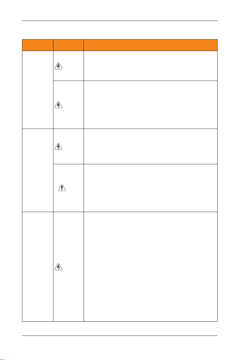
1.1 Safety Cautions
SP200 Manual
Use Stage Safety Grade
Danger
Before
Installation
Danger
Danger
During
Installation
Note
At wiring
Danger
Precautions
Do not install the equipment if you find water seepage,
ª
component missing or damage upon unpacking.
Do not install the equipment if the packing list does not
ª
conform to the product you received.
Handle the equipment with care during transportation to
ª
prevent damage to the equipment.
Do not use the equipment if any component is damaged or
ª
missing. Failure to comply will result in personal injury.
Do not touch the components with your hands. Failure to
ª
comply will result in static electricity damage.
Install the equipment on incombustible objects such as
ª
metal, and keep it away from combustible materials.
Failures to comply may result in a fire.
Do not loosen the fixed screws of the components,
ª
especially the screws withe red marks.
Do not drop wire end or screw into the controller. Failure it
ª
will result in damage to the controller.
Install the controller in places free of vibration and direct
ª
sunlight.
When two controller are laid in the same cabinet ,arrange the
ª
installation positions properly to ensure the cooling effect.
A circuit breaker must be used to isolate the power supply
ª
and the controller. Failure to comply may result a fire.
Ensure that the power supply is cut off before wiring. Failure
ª
to comply may result in electric shock.
Never connect the power cables to the output
ª
terminals(U,V,W) of the controller. Pay attention to the
marks of the wiring terminals and ensure correct wiring.
Failure to comply may result in damage to the controller.
Ensure that the main cable line comply with the standard,
ª
the line meets the EMC requirements and the area safety
standard. Failure to comply may result in risk or accident.
Never connect the power cables the braking resistor
ª
between the DC bus terminals P+, P-. Failure to comply
may result in a fire.
-6 -
SP200 Manual
Chapter1 Safety and cautions
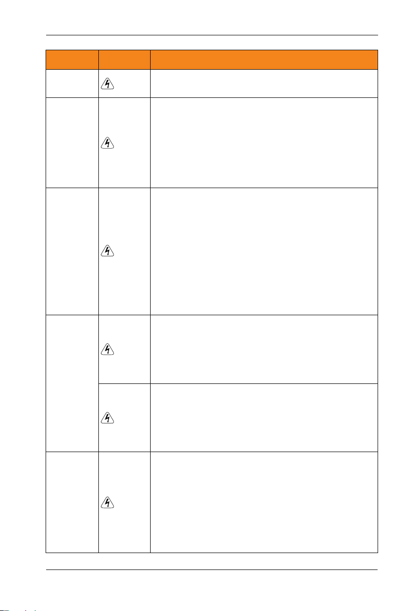
Use Stage Safety Grade
At wiring
Before
Power-on
After
Power-on
Danger
Danger
Danger
Danger
During
Operation
Danger
Precautions
Use a shielded cable for the encoder, and ensure that the
ª
shielding layer is reliably grounded.
Please confirm the peripheral equipment and cable converter
ª
is configured in this manual of the recommended model, all
the configuration line in accordance with the connection
method of the manual provides the correct wiring. Failure to
comply will result in accidents.
Check that the voltage class of the power supply is consistent
ª
with the rated voltage class of the controller.
Do not open the controller’s cover after power-on. Failure to
ª
comply may result in electric shock.
Do not touch the operation of controller during the hands is
ª
wet. Failure to comply will result in accident.
Do not touch any I/O terminal of the controller. Failure to
ª
comply may result in electric shock.
Do not change the default settings of the controller. Failure to
ª
comply will result in damage to the controller.
Do not touch the rotating part of the motor during the motor
ª
auto-tuning or running. Failure to comply will result in
accident.
Signal detection must be performed only by qualified
ª
personnel during operation. Failure to comply will result in
personal injury or damage to the controller.
Do not touch the fan or the discharging resistor to check the
ª
temperature. Failure to comply will result in personal burnt.
Avoid objects falling into the controller when it is running.
ª
Failure to comply will result in damage to the controller.
Do not start or stop the controller by turning the contactor
ª
ON/OFF. Failure to comply will result in damage to the
controller.
After
Power-on
Danger
Do not repair or maintain the controller at power-on. Failure
ª
to comply will result in electric shock.
Ensure that the controller is disconnected from all power
ª
suppliers before staring repair or maintenance on the
controller.
Repair or maintenance of the controller may be performed
ª
only by qualified personnel. Failure to comply will result in
personal injury or damage to the controller.
-7 -

Chapter1 Safety and cautions
SP200 Manual
Use Stage Safety Grade
After
Power-on
Danger
Set and check the parameters again after the controller is
ª
replaced.
Precautions
1.2 Cautions
1.2.1 Motor Insulation Test
Perform the insulation test when the motor is used for the first time, or when it is reused
after being stored for a long time, or in a regular check-up, in order to prevent the poor
insulation of motor windings from damaging the controller during the insulation test. A 500V mega-Ohm meter is recommended for the test. The insulation resistance must not be
less than 5 MΩ.
1.2.2 Thermal Protection of Motort
If the selected controller does not match the rated capacity of the motor , especially when
the rated power of the controller is higher than that of the motor, adjust the parameters for
motor protection in the controller or to install thermal relay to protect the motor .
1.2.3 Running Above Rated Frequency
The controller provides frequency output of 0 to 600.00Hz. If the controller is required to
run at over 50Hz, please consider the capacity of the machine.
1.2.4 Vibration of mechanical device
The controller may encounter the mechanical resonance point at some output frequenc-ies,
which can be avoided by setting the skip frequency. If the operating frequency of the
customer coincide with the resonant frequency please modify the operating frequency or
change the inherent resonance frequency of the mechanical system.
1.2.5 Motor heat and noise
The output of the controller is pulse width modulation (PWM) wave with certain harmonic
frequencies, and therefore, the motor temperature, noise, and vibration are slightly greater
than those when the controller runs at power frequency (50 Hz).
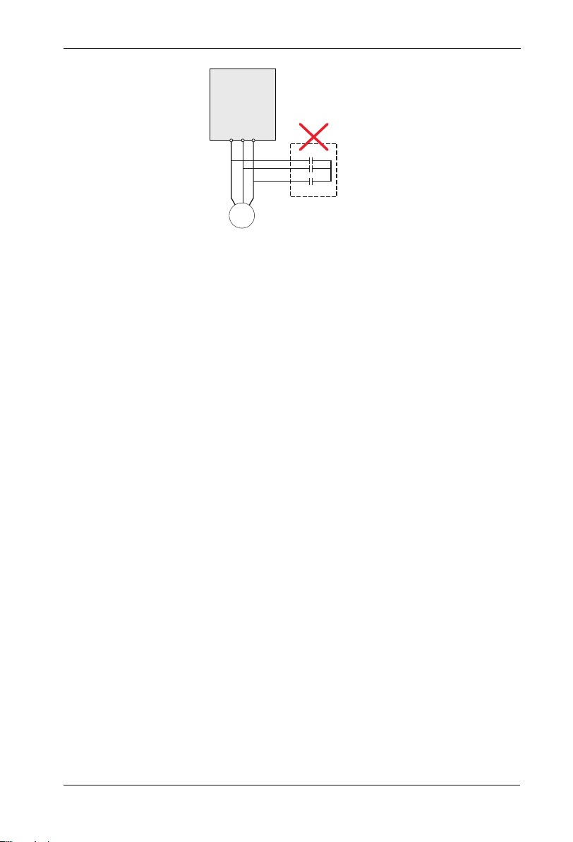
1.2.6 Voltage-sensitive device or capacitor on output side of the controller
Do not install the capacitor for improving power factor or lightning protection voltagesensitive resistor on the output side of the controller because the output of the controller is
PWM wave. Otherwise, the controller may suffer transient overcurrent or even
bedamaged.
-8 -
SP200 Manual
SP200
controller
W
U V
Capacitor or
voltage-sensitive resistor
M
1.2.7 Contactor at the I/O terminal of the controller
When a contactor is installed between the input side of the controller and the power supply,
the controller must not be started or stopped by switching the contactor on or off. If the
controller has to be operated by the contactor, ensure that the time interval between
switching is at least one hour since frequent charge and discharge will shorten the service
life of the capacitor inside the controller.
When a contactor is installed between the output side of the controller and the motor,do not
turn off the contactor when the controller is active. Otherwise, modules inside the controller
may be damaged.
1.2.8 The Use Occasion of the External Voltage Out of Rated Voltage Rage
The controller must not be used outside the allowable voltage range specified in this
manual. Otherwise, the controller’s components may be damaged. If required, use a
corresponding voltage step[-up or step-down device.
Chapter1 Safety and cautions
1.2.9 Change Three Phase Input into Two Phase Input
It is not allowed to change the three phase controller into two phase one . Otherwise , it
may cause it may cause fault or damage the controller.
1.2.10 The Protection of the Lighting Impulse
Although the controller has equipped with lightning overvoltage, overcurrent device, which
has a certain protection function for the induction lightining. For the lightning prone areas,
the user is necessary to install lightning protection device at the front of the controller,
which will benefit to the service life of the transducer.
1.2.11 Altitude and Derating
In places where the altitude is above 1000m and the cooling effect reduces due to thin airit
is necessary to de-rate the controller. Contact Our company for technical support.
-9 -

Chapter1 Safety and cautions
SP200 Manual
1.2.12 Some Special Usages
If writing that is not described in this manual, such as common DC bus is applied, contact the agent or Our company for technical support.
1.2.13 The Cautious of the controller Disposal
The electrolytic capacitors on the main circuits and PCB may explore when they are burnt.
Poisonous gas is generated when the plastic parts are burn. Treat them as ordinary indu-
strial refer to relevant national laws and regulations.
1.2.14 Adaptable Motor
1. The standard parameters of the adaptable motor is adaptable four-squirrel-cage
asynchronous induction motor or PMSM. For other types of motor, select a proper
controller according to the rated motor current.
2. The cooling fan and rotor shaft of general controller are coaxial, which results in reduced
cooling effect when the rotational speed declines. If variable speed is required, add a
more powerful fan or replace.
3. The standard parameters of the adaptable motor have been configured inside the
controller. It is still necessary to perform motor auto-tuning or modify the default values
based on actual conditions. Otherwise, the running result and protection performance
will be affected.
4. The controller may alarm or even be damaged when short-circuit exists on cables or
inside the motor. Therefore, perform insulation short-circuit test when the motor and
cables are newly installed or during routine maintenance. During the test, make sure
that the controller is disconnected from the tested parts.
-1 0-

Chapter 2
Basic principle
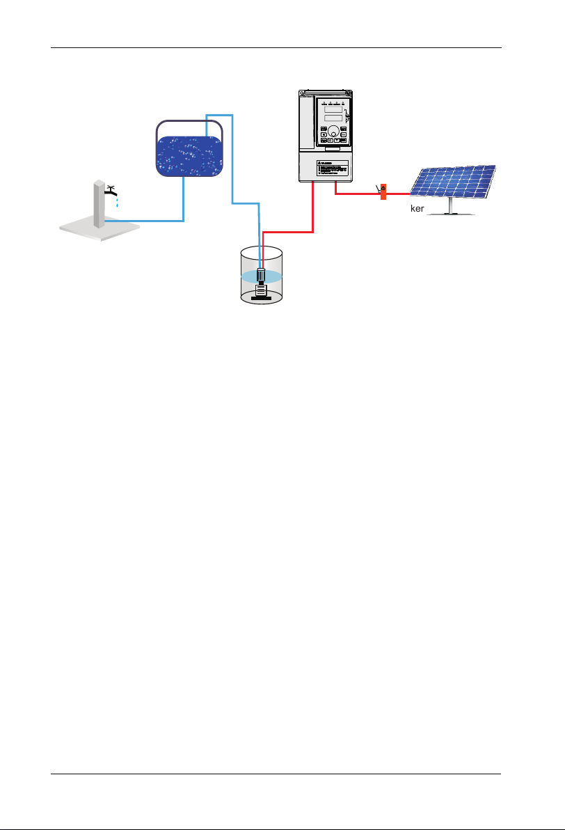
2.1 Basic principle
SP 200 solar pumping system can provide water for remote areas lacking of electricity or
places where the electricity supply is unstable. PV pump controller can convert the DC
power from solar panels to AC power so to drive various kinds of pumps.System enables
continiously pumping when in good weather. System is not equipped with strorage battery
devices, it is suggested that pumping the water to conservation pool for future use.Water
source could come from river, lake,well,or other natural water source or special
soucre.System enables application of floating switch in the conservation pool or water
tower to control the operation of pumps. Low water level probes can be installed in the
well to detect the water level of the well in order to stop the pumps when the well in low
water level. Diagram 1 is a typical SP200 PV pumping system. The main parts and
compenents of this system is after diagram 1.
-11 -
Chapter2 Basic principle
SP200 Manual
C.SP200 PV pump controller
F.Storage tank
A.solar panels
B.DC circuit braker
E. well water
level switch
2-1 SP200 PV pumping system
D.pump
SP200 PV pumping system is composed of following parts:
A: Solar panels
:
B DC circuit braker or disconnector
:
C SP200 PV pump controller
:
D Pump
:
E well water level switch(optional)
:
F water tower water level switch(optional)
P
S 200 PV pump controller can start the pump softly and is consistent with the electricity
coming from the changes providing by solar panels. The advantage of soft starting is avoid
surge or power surges when the pump or motor are in the process of starting,whi-ch
reduce the loss of motor and pumping system.
Requirements of pump check valve:
Note: To ensure the best reliability of the system and water supply, check valves is required
to be installed in the output pipe. The first check valves must be installed in the outlet of
pumps, the rest check valves should be installed in the vertical direction of the pipes of
every 30 meters(100 feet) behind the pump.
-1 2-

SP200 Manual
Chapter2 Basic principle
2.2 Functions
System diagnostics
SP200 PV pump controller continuously monitor the system performance and can detect a
variety of abnormal circumstance. In most cases, controller provide compensations as
required to keep the non-stop operation of the system. If there is a damage, controller will
protect the system and display fault state. If possible, controller will restart after the fault
status is gone. Fault codes and correction information please refer to the chapter of
Detecting and troubleshooting.
Motor soft-starter
Generally speaking, S 200pv pump controller will operate when there is water requirement or electricity is available.Everytime SP200 PV Pump Controller detect the water
requirement, the rotating speed is always improved slowly and at the same time add motor
voltage gradually.Compared to traditional water supply system, solar pumping sytem's
motor temperature and starting current is much lower. Controller with soft starting function
has no damage to the motor.
Overheating monitoring
P
S 200 PV pump controller can run at full power when the ambient temperature reaches
45℃ For temperature above 45℃, controller will keep on running by reducing output
power. When the controller temperature cooled to safety point, it will run at full power
output.
P
Water level float switch
P
S 200 PV pump controller can connect 2 water level detecting switch to detect pump
running by remote control. Water level switch is optional to the controller, it is not required.
SP200 PV pump controller's input power terminals can be switched to spare AC power
supply manually.
Spare AC power supply switch
Note: Based on different models, SP200 input power could be 220v AC single power, or
380V AC 3 phase power. For more information, please contact SINOVO or certified agent.
When the system is running by spare AC power, please check the DC power every 30 mins.
If the AC power is applicable, then stop the controller and switch to the AC power and try to
run the pump at the AC power driving way.
-1 3-

Chapter2 Basic principle
SP200 Manual
Note:
DC circuit switching and generator power switch installation are required and both switches
should be mutually locked to prevent they were connected at the same time which lead to
the solar panels and generator connect SP200 controller simultaneously. Please check if
the design meets electrical specifications of relative country and area.
-1 4-

Chapter 3
Product Information
200 PV pump controller is adjustable speed motor controller designed in accordance
SP
with any IEC standard 3 phase asynchronous motor。 SP200 PV pumping system convert
the high voltage DC power of solar array into AC power to drive an standard 3 phase
asynchronous motor thus provide water for remote areas. When the solar power is not
enough, controller can be switched manually to spare single or 3 phase AC power, such as
generator. This controller is functioned with fault detection, motor soft-starting, and speed
control.SP200 PV Pump Controller is designed with the function of plug-and-play and easy
to install.SP200 PV Pump Controller is a product of stable performance and high standard.
In weak light condition, controller will try to drive pump for water lifting, but if the light is
becoming weaker, then controller will reduce the speed of pump to protect the system
components from damaged and shut down during some extreme circumanstances.When
the special circumanstances is gone, controller will restart driving the pump.
-1 5-

Chapter3 Product Information
SP200 Manual
3.1 Inspection
Before using, please check the SP200 PV pump controller components firstly. Please make
sure the components serial number is correct and if the product is damaged during
shipping.
3.2 Instroductions and Feature
SP200 PV Pump Controller monitor the system performance continiously and with
integrated protection of multi-function pump system. When fault occurs, SP200 PV Pump
Controller will display the type of faults by LED screen in the front of the controller and will
automatically reset routine fault.
Internal Diagnostics allows lower input voltage.
Whenever possible, the controller will maximize the use of the solar array output to drive
the pump.
To provide users with an easy interface, enhanced configurability and realize remote
monitoring system.
3.3 Protection Function
Electronic monitoring enables the controller to monitor systems and automaticlly shut down
in following circumanstances:
1. Wells is short of water- Low liquild level swtiches;
2. Pump locked rotor overload protection;
3. High voltage surge;
4. Low output voltage;
5. Motor lack phase;
6. Short circuit;
7. Over heating.
Note:
the controller protect the motor by limiting load running when the motor current exceeds the
rated current at the time of low water leve.The controller does not provide high motor
temperature detection.
-1 6-
SP200 Manual
Chapter3 Product Information
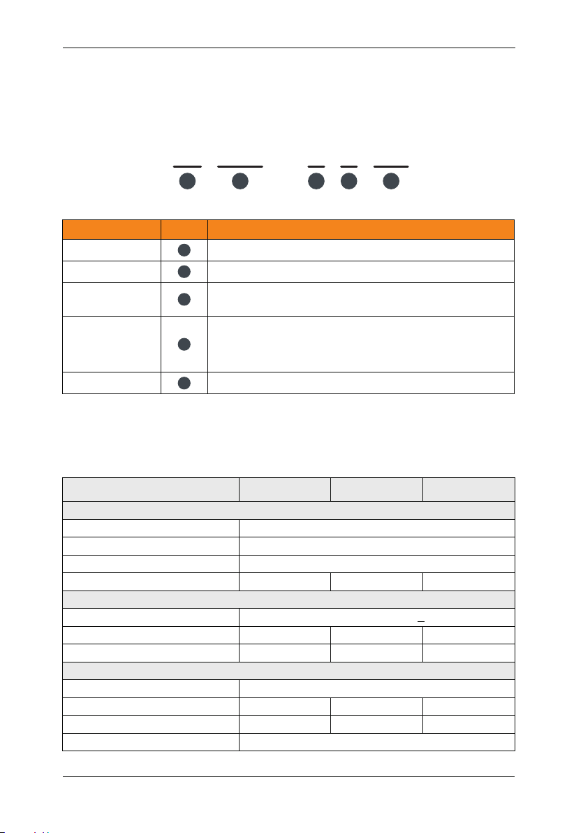
3.4 Naming Rules
In the model code contains the product information Users can find the code from the
transducerand simple nameplate.
SP
Field Mark
controller series
Series number
Voltage Level
voltage range
Pump rated power
200
1
1
2
3
4
5
2
Solar water pump controller
Series second generation
2: Three-phase 220V
4 Three-phase 380V:
S Rated voltage310VDC,Recommended voltage range
(MTTP)180VDC~360VDC
T: : Rated voltage540VDC,Recommended voltage range
(MTTP)500VDC~600VDC
2.2: 2.2KW
Figure 3-1 Name Designation Rules
-
4
3
Content
T
4
2.2
5
3.5 SP200 PV Pump Controller input/output parameter
SP200-2SXXX
Model
PV array input parameter
Max voltage V ( )input
Min input voltage V ( )
Recommended voltage mpp)(
Recommended PV power(Kw)
Input voltage(V)
Max current A ( )
Generator capacity kVA ( )
Rated output voltage
Max current A( )
Rated output power kW( )
Output frequency
0.9 1.2~
Spare AC generator
Singel phase AC 200-240(+10%)
8.2
1.5
Output parameter
4.7
0.75
DC 450V
DC 180V
DC 280~360V
1.8~2.4
14
3
3-phase AC 200-240V
7.5
1.5
0~50Hz/60Hz
SP200-2S-2.2SP200-2S-0.7 SP200-2S-1.5
2.7 3.5~
23
4
10
2.2
-1 7-
Chapter3 Product Information
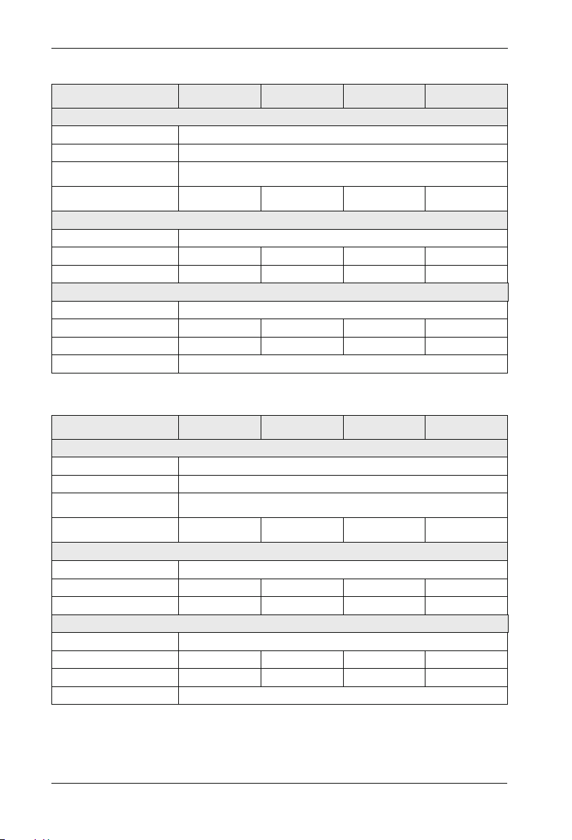
SP200-4TXXX Input/output parameter
Model
PV array input parameter
Max voltage V ( )input
Min input voltage V ( )
Recommended
voltage(mpp)
Recommended
PV power(Kw)
Input voltage(V)
Max current A ( )
Generator capacity kVA ( )
Rated output voltage
Max current A( )
Rated output power kW( )
Output frequency
2.7 3.5~
Spare AC generator
5.8
4
Output parameter
5.1
2.2
SP200-4T-5.5SP200-4T-2.2 SP200-4T-3.7
DC 800V
DC 350V
DC 500~600V
4.8~6.4
3-phase AC 380/400/415/440V(+15%)
10.5
5.9
3-phase AC 380/400/415/440V(+15%)
9
3.7
0~50Hz/60Hz
6.6~8.8
14.6
8.9
13
5.5
SP200 Manual
SP200-4T-7.5
9~12
20.5
11
17
7.5
Model
Max voltage V ( )input
Min input voltage V ( )
Recommended
voltage(mpp)
Recommended
PV power(Kw)
Input voltage(V)
Max current A ( )
Generator capacity kVA ( )
Rated output voltage
Max current A( )
Rated output power kW( )
Output frequency
PV array input parameter
13.2~17.6
Spare AC generator
3-phase AC 380/400/415/440V(+15%)
26
17
Output parameter
3-phase AC 380/400/415/440V(+15%)
25
11
-1 8-
DC 500~600V
18~24
35
21
32
15
0~50Hz/60Hz
SP200-4T-18.5SP200-4T-11 SP200-4T-15
DC 800V
DC 350V
22.2~29.6
38.5
24
37
18.5
SP200-4T-22
26.4~35.2
46.5
30
45
22
 Loading...