

Sinovo SD300-4T-0.7G, SD300-2T-1.5G, SD300-2T-2.2G, SD300-4T-1.5G, SD300-4T-2.2G User Manual
...
SD300 D rive Us e Manua l (Ver sion: 2 .4)
Open/Close Vector Control Inverter
SD
003
AC DRIVE
User Manual
SHENZHEN SINOVO ELECTRIC TECHNOLOGY CO.,LTD
Add :
5th F loor, No . D Build ing, Hu afeng I ntern ation al Robo t
Ind ustry P ark, Xi xiang S treet ,Hang cheng R oad, Ba oan
Dis trict , Shenz hen Cit y
Tel 075 5 29 78487 0
: ( )
Fax : (0755 )2978 4969
Tech su ppor: 4 00-88 1-868 9
htt p://w ww.sin ovo-v fd.co m
Version: 2.4

SD300 User Manual
Preface
Preface
Thank y ou for pu rchas ing the S D300 se ries AC d rive developed b y Our com pany.
SD300 s eries A C drive is a gen eral- purpo se high -perf orman ce vect or cont rol AC
drive , and it i s mai nly u sed f or co ntrol ling and r egula ting the s peed and t orque of t he
three -phas e AC as ynchr onous motor . It is a ne w ge nerat ion of AC Dri ve with la test
techn ology . SD 300 serie s is c harac teriz ed i n the high- perfo rmanc e current v ector
contr ol tec hnolo gy, hi gh tor que ou tput at lo w freq uency and st rong ove rload capac ity.
It po ssess go od stabili ty, dyna mic perf orman ce, commun icati on bus functi ons, ric h
power ful and stable perf ormance, and suppor ts for multi -PG car ds, wit h per fect an ti-
tripp ing con trol and the abil ity to adapt to bad powe r grid. It i s used to driv e var ious
autom atic pr oduct ion equip ments involv ing the indust ry of tex tile, paperm aking , wire
drawi ng, mac hine to ols, pa ckagi ng, food, fans and pumps an d so on.
SD300 Series AC drive Features
Multiple Control Modes:
ªSuppo rts mul tiple c ontro l modes : vecto r V/F con trol, s ensor less vector speed c ontro l,
senso rless v ector t orque c ontro l, sens or vect or spee d contr ol and sensor vecto r torqu e
contr ol .
Advanced Vector Control Algorithm:
ªThe op timiz ed VF c ontro l and s ensor less v ector contr ol is m ore st able a t low s peed,
more powerf ul in the abilit y of low fr equen cy tor que ou tput and with bett er dyn amic
respo nse and both the sens orles s vecto r an d se nsor v ector m ode suppo rt s peed
contr ol and to rque co ntrol .
Small and Compact Volume:
ªIn t he f ull power ran ge, the sam e po wer type c ompar ed to the old produ cts EH600 , it
reduc es th e vol ume of 20%~40 %. As the volume is red uced, the optimize d the rmal
desig n ensur es the favor able te mpera ture ri se of t he whol e AC driv e.
The op timiz ed VF cont rol an d sens orles s ve ctor contro l is more stable at low spe ed,
more powerf ul in the abi lity of low freque ncy to rque output and wit h bett er dyn amic
respo nse and bot h the senso rless v ector a nd s ensor v ector mod e suppo rt spee d co ntrol
and tor que con trol.
Unpacking Inspection Cautions
Every AC Drive hav e been te sted strictly in facto ry pri or to shipm ent. U pon unpa cking ,
check :

Preface
SD300 User Manual
ªWheth er the pr oduct i s damag ed;
ªWheth er the na mepla te of mod el and AC d rive ra tings are consis tent wi th your o rder.
ªWheth er the box contai ns the AC drive , ce rtifi cate of confo rmity , us er manu al and
warra nty car d. If you f ind any o mission or damag e, cont act Our c ompan y or your s uppli er
immed iatel y.
First-time Use
For the use rs who us e th is prod uct for t he f irst ti me, rea d the manua l caref ully. I f in d oubt
conce rning some f uncti ons or perfo rmanc es, contact the techn ical s uppor t pers onnel of
Our com pany to e nsure c orrec t use.
SD300 series AC drives have passed CE test and also meet the requirements of following International Standard.
ªIEC/E N 6180 0-5-1 :2003 S afety r equir ement s for a djust able speed elec tric d rive
syste ms.
ªIEC/E N 61800 -3:20 04 adju stabl e speed elec tric dr ive sys tems: (The third par)th e
elect romag netic c ompat ibili ty stan dard of the produc t and its s pecif ic test m ethod .
ªIE C/EN 61 000-2-1 ,2 -2 ,3-2,3- 3, 4- 2, 4-3,4 -4 ,4 -5 ,4-6: EM C Int er na ti onal an d E U
Stand ards.
The i nstru ction s are s ubjec t to chan ge, w ithou t notic e, d ue to produc t u pgrad e,
speci ficat ion modif icati on as well as e ffort s to i ncrea se the accu racy an d conve nienc e of
the man ual.
-2-

SD300 User Manual
Contents
Contents
Preface.......................................................................................................................................01
Contents....................................................................................................................................03
Chapter 1 Safety and Cautions.........................................................................................07
1.1 Safet y an d Ca ution s De finit ion
1.2 Sa fety C autio ns
1.3 Cauti ons
..... ..... ..... ..... ..... ..... ..... ..... ..... ..... ..... ..... ..... ..... ..... ..08
..... ..... ..... ..... ..... ..... ..... ..... ..... ..... ..... ..... ..... ..... ..... ..... ..... ..10
Chapter 2 Product Information.........................................................................................15
2.1 Chapter of Thi s Conte nt... ..... ..... ..... ..... ..... ..... ..... ..... ..... . .... ..... ..... .
2.2 Ba sic P rinci ple.. ..... ..... ..... ..... ..... ..... ..... ..... ..... ..... ..... ..... ..... ..... .....
2.3 Na ming Rule s.... ..... ..... ..... ..... ..... ..... ..... ..... ..... ..... ..... ..... ..... ..... .....
2.4 N amepl ate.. ..... ..... ..... ..... ..... ..... ..... ..... ..... ..... ..... ..... ..... ..... ..... ..... .
2.5 SD300 Ser ies of A C drive ..... ..... ..... ..... ..... ..... ..... ..... ..... ..... ..... ..... .
2.6 Techn ical Sp ecifi catio ns... ..... ..... ..... ..... ..... ..... ..... ..... ..... ..... ..... .....
2.7 St ructu re Di agram ..... ..... ..... ..... ..... ..... ..... ..... ..... ..... ..... ..... ..... ..... ..
2.8 Pe ripheral El ectri cal Compo nents Sys tem Struc ture. ..... ..... ..... ..... ...
2.9 SD300 O ption al Part s.... ..... ..... ..... ..... ..... ..... ..... ..... ..... ..... ..... ..... ....
2.10 Conn ectio n M ethod s.... ..... ..... ..... ..... ..... ..... ..... ..... ..... ..... ..... ..... ...
..... ..... ..... ..... ..... ..... ..... ..... ..... ..... ..... .07
. 15
15
17
17
18
19
22
27
30
33
Chapter 3 Mechanical and Electrical Installation........................................................35
3.1 Chapter of Thi s Conte nt... ..... ..... ..... ..... ..... ..... ..... ..... ..... ..... ..... ..... ..35
3.2 Me chani cal I nstal latio n.... ..... ..... ..... ..... ..... ..... ..... ..... ..... ..... ..... ..... .36
3.3 Stand ard Wir ing.. ..... ..... ..... ..... ..... ..... ..... ..... ..... ..... ..... ..... ..... ..... ....4 1
3.4 La yout Prote ction ..... ..... ..... ..... ..... ..... ..... ..... ..... ..... ..... ..... ..... ..... ...51
Chapter 4 Operation, Display and Application Examples.........................................53
4.1 Chapter of thi s Conte nt... ..... ..... ..... ..... ..... ... ..... ..... ..... ..... ..53
4.2 In trodu ction of the Keyp ad... ..... ..... ..... ..... ..... ..... ..... ..... ..... ..... ..... ...54
4.3 Disp lay of K eypad ..... ..... ..... ..... ..... ..... ..... ..... ..... ..... ..... ..... ..... ..... ...56
4.4 Ke ypad Oper ation ..... ..... ..... ..... ..... ..... ..... ..... ..... ..... ..... ..... ..... ..... ...57
..... ..... ...
Chapter 5 Function Parameter Table..............................................................................59
5.1 Chapter of thi s Conte nt... ..... ..... ..... ..... ..... ..... ..... ..... ..... ..... ..... ..... ...59
5.2 Fun ction Param eter T able. ..... ..... ..... ..... ..... ..... ..... ..... ..... ..... ..... ..... 60
-3-

Contents
SD300 User Manual
Chapter 6 Parameter Description.....................................................................................93
Group F00 : Ba sic Fun ction Gro up... ..... ..... ..... ..... .... ..... ..... ..... ..... ..... ...94
Group F01 : St art-s top Con trol Grou p.... ..... ..... ..... ..... ..... ..... ..... ..... ..... 101
Group F02: Motor 1 Pa ramet er Gro up... ..... ..... ..... ..... ..... ..... ..... ..... ..... .107
Group F0 3: Vecto r Cont rol Grou p.... ..... ..... ..... ..... ..... ..... ..... ..... ..... ..... .111
Group F0 4: V/Fco ntrol Gr oup.. ..... ..... ..... ..... ..... ..... ..... ..... ..... ..... ..... ....1 15
Group F0 5: Input Termi nal Grou p.... ..... ..... ..... ..... ..... ..... ..... ..... ..... ..... .121
Group F06 : Outp ut T ermin al G roup. ..... ..... ..... ..... ..... ..... ..... ..... ..... ..... ..129
Group F 07: HMI Gro up... ..... ..... ..... ..... ..... ..... ..... ..... ..... ..... ..... ..... ..... ...13 5
Group F08: Stre ngthe n th e Fu nctio nal Gr oups. ..... ..... ..... ..... ..... ..... ..... .141
Group F 09: PID Con trol Gr oup.. ..... ..... ..... ..... ..... ..... ..... ..... ..... ..... ..... ...14 8
Group F0A:W obble , Le ngth, Count and Timin g Pa ramet er Gro up... ..... ..159
Group F0B: Simp le PLC and Multi -spee d Co ntrol Group ..... ..... ..... ..... ...16 2
Group F0C : Pr otect ion Par amete r Gr oup.. ..... ..... ..... ..... ..... ..... ..... ..... ...16 6
Group F0D : Mo tor 2 Pa ramet er G roup. ..... ..... ..... ..... ..... ..... ..... ..... ..... ...17 1
Group F0E: Serial Co mmuni catio n Func tion G roup. ..... ..... ..... ..... ..... ....1 76
A00: Torq ue C ontrol and Limi t Fu nctio nal Group ..... ..... ..... ..... ..... ..... ....1 78
A01: A 1 Cu rve Setti ng F unction Gro up... ..... ..... ..... ..... ..... ..... ..... ..... ..... 182
A02: S tatus Ch eck Fu nctio n Grou p.... ..... ..... ..... ..... ..... ..... ..... ..... ..... ....1 84
A03 : DP Par a met e r G rou p ... . ... . .. . ... . ... . ... . ... . .. . ... . ... . ... . ... . ... . .. . 185
..
Chapter 7 EMC.....................................................................................................................197
7.1 Definition o f Relat ed Term s.... ..... ..... ..... ..... ..... ..... ..... ..... .. .. ..... ...19 8
7.2 EMC Stand ard Intro ducti on... ..... ..... ..... ..... ..... ..... ..... ..... ..... ..... ..... 198
7.3 Selec tion of Per ipher al EMC Devi ces.. ..... ..... ..... ..... ..... ..... ..... ..... ..199
7.4 Shi elded Cable ..... ..... ..... ..... ..... ..... ..... ..... ..... ..... ..... ..... ..... ..... ..... 203
7.5 Req uirement for Lea kage Cu rrent ..... ..... ..... ..... ..... ..... ..... ..... ..... ....2 05
7.6 Sol ution s to Common E MC Inte rfere nce Pro blems . ..... ..... ..... ..... ...20 6
..
Chapter 8 Troubleshooting and Maintenance...........................................................207
8.1 Daily R epair a nd Mainte nance ... ..... . ..... ..... .208
8.2 War ranty Ag reeme nt... ..... ..... ..... ..... ..... ..... ................................. .209
8.3 Cont ents o f Th is Cha pter. ..... ..... ..... ............................ ..... ..... ..... ..209
8.4 Ala rm and Fault In ducti ons.. ..... ..... ..... ................................. ..... ...21 0
8.5 Fault Res et... ..... ..... ..... ..... ................................. ..... ..... ..... ..... ..... 210
8.6 Fault Hi story ..... ..... ..... ..... ..... ..... ..... ..... ................................. ..... .210
8.7 Fault I nstru ction a nd Solution... ............................ ..... ..... ..... ..... ....2 10
8.8 Comm on F ault A nalys is... ..... ..... ..... ..... ..... ..... ..... ..... ....................215
..... ..... ..... ..... ..... ..... .. ..
-4-

SD300 User Manual
Contents
Chapter 9 Communication Protocol.............................................................................221
9.1 Netw orkin g Mode ..... ..... ..... ..... ..... ..... ..... ..... ..... ..... ..... ..... ..... .221
9.2 In terfa ce Mo de... ..... ..... ..... ..... ..... ..... ..... ..... ..... ..... ..... ..... ..... ..... ..222
9.3 Pr otoco l Frame For mat.. ..... ..... ..... ..... ..... ..... ..... ..... ..... ..... ..... ..... ..222
9.4 Funct ion Pro tocol ..... ..... ..... ..... ..... ..... ..... ..... ..... ..... ..... ..... ..... ..... ..223
9.5 Co mmuni catio n Param eters Add ress. ..... ..... ..... ..... ..... ..... ..... ..... ...22 6
..... .
-5-


Chapter 1
Safety and Cautions
1.1 Safety and Cautions Definition
Read this man ual care fully so that you hav e a thor ough und ersta nding . Installa tion,
commi ssion ing or m ainte nance ma y b e p erfor med in conj uncti on with this cha pter. Ou r
compa ny w ill ass ume no abil ity and r espon sibil ity for any i njury or los s ca used by
impro per ope ratio n.
Danger
Opera tions whi ch are not perfor med compl y with the requ ireme nts may cause sev ere
hurt or e ven dea th.
Note
Opera tions w hich are not perf ormed comply with requ ireme nts may caus e perso nal
injur y or prop erty da mage.
-7-
Chapter 1 Safety and Cautions
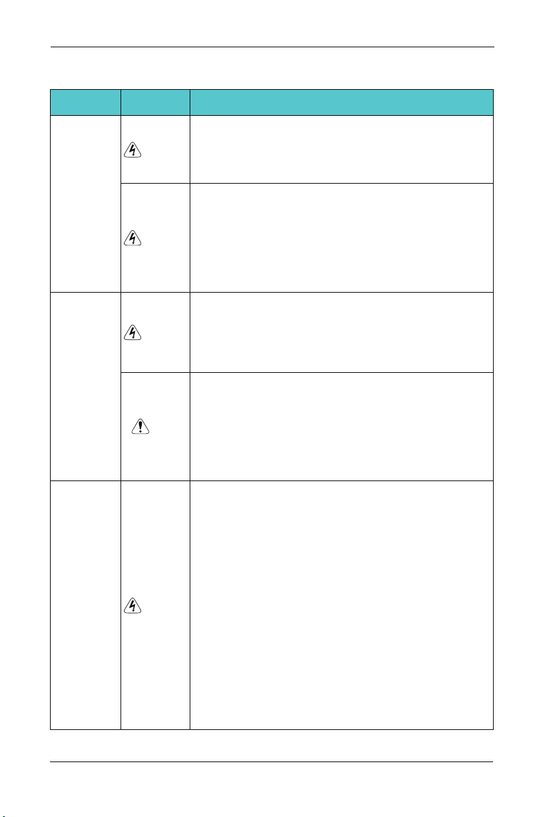
1.2 Safety Cautions
SD300 User Manual
Use Stage Safety Grade
Danger
Befor e
Insta llati on
Danger
Danger
Durin g
Insta llati on
Note
At wiri ng
Danger
Precautions
Do not in stall t he equi pment i f you fin d water seepage,
ª
compo nent mi ssing o r damag e upon unpacking.
Do not in stall t he equi pment i f the pac king list does not
ª
confo rm to the p roduc t you rec eived .
Handl e the equ ipmen t with ca re duri ng transportat ion
ª
to prev ent dam age to th e equip ment.
Do not us e the equ ipmen t if any co mpone nt is damaged
ª
or miss ing. Fa ilure t o compl y will re sult in personal
injur y.
Do not to uch the c ompon ents wi th your h ands. F ailure
ª
to comp ly will r esult i n stati c elect ricit y damage.
Insta ll the eq uipme nt on inc ombus tible objects such as
ª
metal , and kee p it away f rom com busti ble mat erials.
Failu res to co mply ma y resul t in a fire .
Do not lo osen th e fixed s crews o f the com ponen ts,
ª
espec ially t he scre ws with e red mar ks.
Do not dr op wire e nd or scr ew into t he AC dri ve. Fai lure
ª
it will r esult i n damag e to the AC d rive.
Insta ll the AC d rive in p laces f ree of vi brati on and direct
ª
sunli ght.
When tw o AC driv es are la id in the s ame cab inet
ª
,arra nge the i nstal latio n posit ions properly to ensure
the coo ling ef fect.
A circu it brea ker mus t be used t o isola te the po wer
ª
suppl y and the A C drive . Failu re to com ply may r esult a
fire.
Ensur e that th e power s upply i s cut off b efore w iring .
ª
Failu re to com ply may r esult i n elect ric sho ck.
Never c onnec t the pow er cabl es to the o utput
ª
termi nals( U,V,W ) of the AC d rive. P ay atte ntion t o the
marks o f the wir ing ter minal s and ens ure correct
wirin g. Fail ure to co mply ma y resul t in damage to the
AC driv e.
Ensur e that th e main ca ble lin e compl y with th e
ª
stand ard, th e line me ets the E MC requ ireme nts and
the are a safet y stand ard. Fa ilure t o compl y may res ult
in risk o r accid ent.
Never c onnec t the pow er cabl es the br aking resistor
ª
betwe en the DC b us term inals P +, P-. Fa ilure t o
compl y may res ult in a fi re.
-8-
SD300 User Manual
Chapter 1 Safety and Cautions
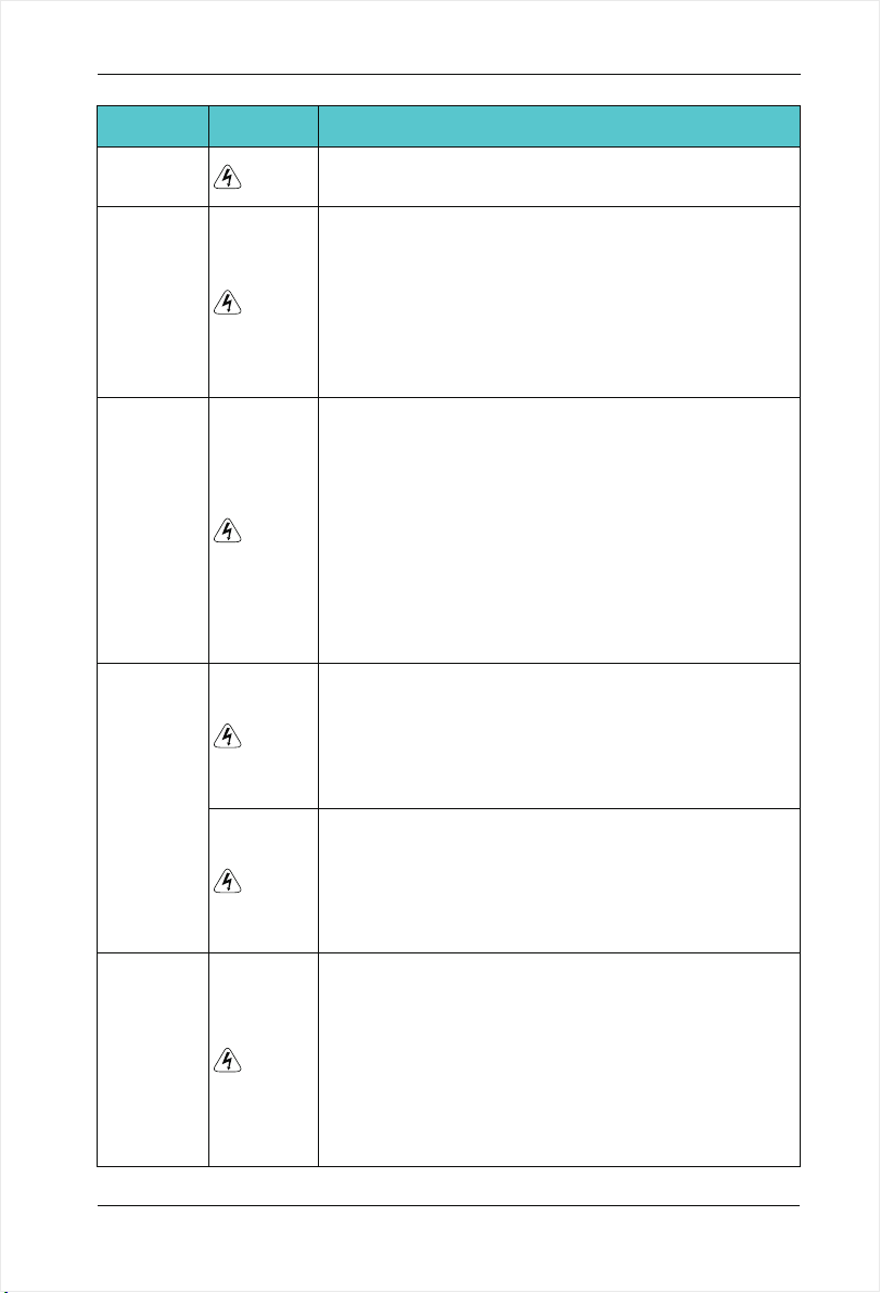
Use Stage Safety Grade
At wiri ng
Befor e
Power -on
After
Power -on
Danger
Danger
Danger
Danger
Durin g
Opera tion
Danger
Precautions
Use a shi elded c able fo r the enc oder, and ensure that
ª
the shi eldin g layer i s relia bly grounded.
Pleas e confi rm the pe riphe ral equ ipment and cable
ª
conve rter is c onfig ured in t his man ual of th e
recom mende d model , all the c onfig uration line in
accor dance w ith the c onnec tion me thod of the manual
provi des the c orrec t wirin g. Fail ure to co mply will result
in acci dents .
Check t hat the v oltag e class o f the pow er supp ly is
ª
consi stent w ith the r ated vo ltage c lass of t he AC dri ve.
Do not op en the AC d rive’ s cover a fter po wer-o n.
ª
Failu re to com ply may r esult i n elect ric sho ck.
Do not to uch the o perat ion of AC d rive du ring th e
ª
hands i s wet. Fa ilure t o compl y will re sult in a ccident.
Do not to uch any I /O term inal of t he AC dri ve. Fai lure
ª
to comp ly may re sult in e lectr ic shoc k.
Do not ch ange th e defau lt sett ings of t he AC dri ve.
ª
Failu re to com ply wil l resul t in dama ge to the AC drive.
Do not to uch the r otati ng part o f the mot or duri ng the
ª
motor a uto-t uning o r runni ng. Fai lure to c omply will
resul t in acci dent.
Signa l detec tion mu st be per forme d only by q ualified
ª
perso nnel du ring op erati on. Fai lure to comply wil l
resul t in pers onal in jury or d amage t o the AC drive.
Do not to uch the f an or the d ischa rging r esist or to
ª
check t he temp eratu re. Fai lure to c omply w ill result in
perso nal bur nt.
Avoid o bject s falli ng into t he AC dri ve when it is
ª
runni ng. Fai lure to c omply w ill res ult in damage to the
AC driv e.
Do not st art or st op the AC d rive by t urnin g the
ª
conta ctor ON /OFF. F ailur e to comp ly will r esult i n
damag e to the AC d rive.
After
Power -on
Danger
Do not re pair or m ainta in the AC d rive at p ower-on.
ª
Failu re to com ply wil l resul t in elec tric shock.
Ensur e that th e AC driv e is disc onnec ted fro m all
ª
power s uppli ers bef ore sta ring re pair or maintena nce
on the AC d rive.
Repai r or main tenan ce of the A C drive m ay be
ª
perfo rmed on ly by qua lifie d perso nnel. Failure to
compl y will re sult in p erson al injury or damage to the
AC driv e.
-9-
Chapter 1 Safety and Cautions
SD300 User Manual
Use Stage Safety Grade
After
Power -on
Danger
Set and c heck th e param eters a gain af ter the A C drive
ª
is repl aced.
Precautions
1.3 Cautions
1.3.1 Requirement on Residual Current Device(RCD)
The AC dr ive gene rates high lea kage c urren t d uring runni ng, whic h flow s earthi ng (PE )
condu ctor. Th us insta ll a t ype-B RC D a t t he trans ient and st eady- state le akage cu rrent
to gro und that may b e ge nerat ed at star tup and du ring runn ing of the AC dri ve. You ca n
selec t a sp ecial ized RC D with th e funct ion of su ppressing high harmon ics or ge neral -
purpo se RCD wi th rela tivel y large r esidual curren t.
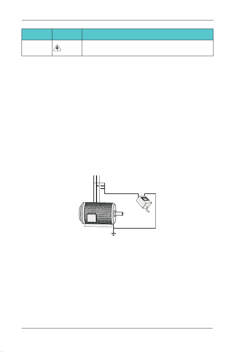
1.3.2 Motor Insulation Test
Perfo rm the insul ation test when the mo tor is used for t he fir st tim e, o r when it is reused
after be ing stor ed for a lo ng time, or in a reg ular che ck-up , i n o rder to pre vent the po or
insul ation of mo tor windi ngs fro m damag ing the AC driv e durin g the insul ation test. A
500-V meg a-Ohm m eter is rec ommen ded for t he t est. Th e insul ation res istan ce must not
be less t han 5 MΩ.
UVW
Input termina ls of the motor
Megger
Ground
1.3.3 Thermal Protection of Motort
If t he s elect ed A C drive doe s no t ma tch the rat ed c apaci ty o f the motor , espec ially w hen
the rated p ower of t he AC drive i s highe r than that o f the mot or, adjus t the par amete rs for
motor p rotec tion in t he AC dri ve or to in stall t hermal relay to protect the moto r .
1.3.4 Running Below and Above Rated Frequency
The AC dri ve pr ovide s fre quenc y out put of 0 to 600.00 Hz. When the us ers use the
frequ ency in verte r for a long ti me, ple ase pay attent ion to th e motor coolin g or use of
varia ble fre quenc y mot or. If the A C drive is req uired to r un at o ver 50H z, co nside r the
capac ity of th e machi ne.
-10-
SD300 User Manual
Chapter 1 Safety and Cautions
1.3.5 Vibration of mechanical device
The AC dr ive may e ncoun ter the m echan ical resonance p oint at s ome out put fre quenc ies,
which c an be avo ided by s ettin g the ski p frequency. If the operating fr equen cy of the c us-
tomer c oinci de with t he reso nant fr equency please modify t he oper ating f reque ncy or
chang e the inh erent r esona nce fre quency of the mechanica l syste m.
1.3.6 Motor heat and noise
The ou tput of the AC dri ve i s puls e wi dth modulat ion (PWM) wav e with cer tain harm onic
frequ encie s, and there fore, the motor t emper ature , noi se, and vibr ation are sligh tly
great er than t hose wh en the AC d rive ru ns at pow er frequency (50 Hz).
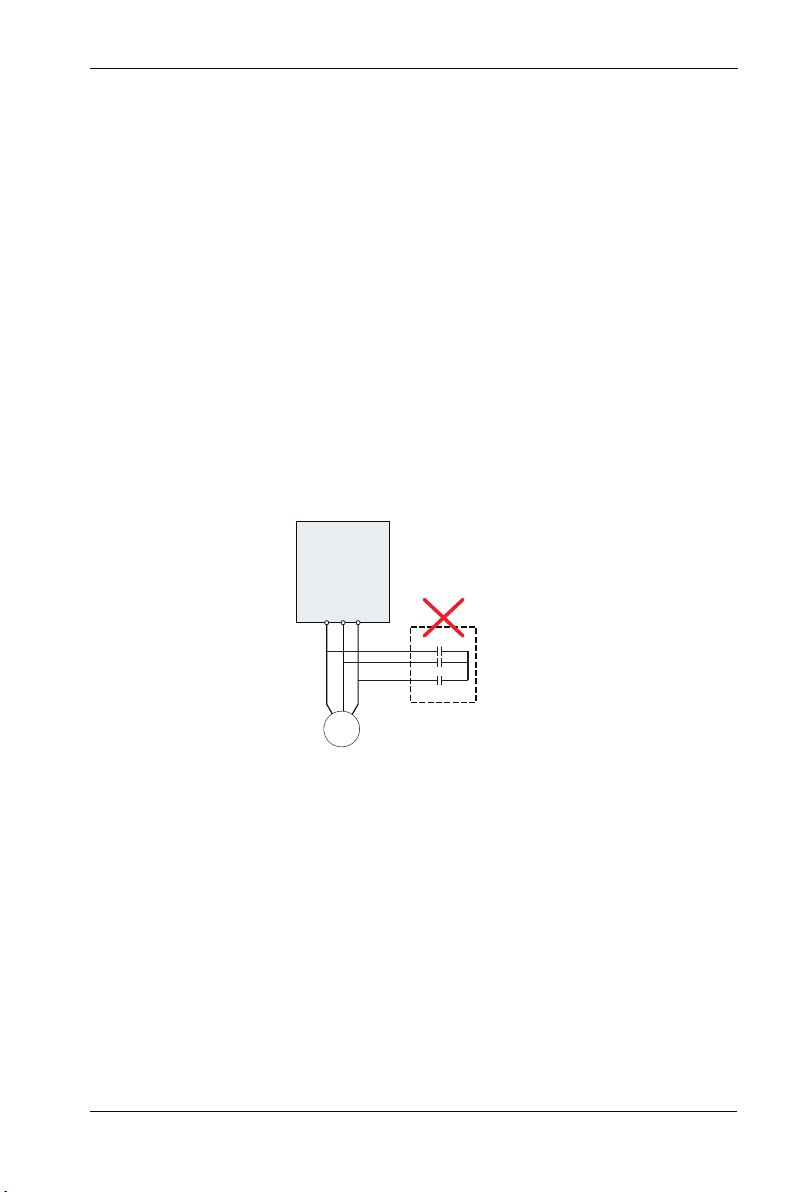
1.3.7 Voltage-sensitive device or capacitor on output side of the AC drive
Do not in stall t he capa citor f or impr oving p ower factor or lig htnin g prote ction v oltag esen-
sitiv e resis tor on th e outpu t side of the AC dri ve beca use the outp ut of the AC drive is
PWM w ave. Ot herwi se, t he AC d rive ma y suffe r trans ient ov ercur rent or even
bedam aged.
AC Driver
W
U V
Capacitor or
M
voltage-sensitive resi stor
1.3.8 Contactor at the I/O terminal of the AC drive
When a co ntact or is ins talle d betw een the input side of th e AC driv e and the power
suppl y, the AC driv e must not be star ted or sto pped by sw itchi ng t he c ontac tor on or off.
If the AC d rive ha s to b e opera ted by th e conta ctor, e nsure t hat the t ime int erval b etwee n
switc hing is at le ast one ho ur since freq uent charg e and di schar ge wi ll short en th e
servi ce life o f the cap acito r insid e the AC dr ive.
When a co ntact or is ins talle d b etwee n the out put si de of the AC drive and the m otor, do
not tu rn o ff t he c ontac tor wh en t he A C dr ive is act ive. Othe rwise , mo dules insid e th e AC
drive m ay be dam aged.
-11-

Chapter 1 Safety and Cautions
SD300 User Manual
Contactor KM
380Vac
50/60Hz
Do n ot start/stop the AC drive by
switching the contactor on/off. If
the AC drive has to be operated
by the contact or, ensure that the
tiome interval is at least one hour.
R
S
AC Driver
T
Cont actor KM or
offer switche s
U
V
W
Turn on / off the contactor when
the A C d rive h as no ou tput.
Other wise,m odifies inside the AC
drive ma y be damaged.
M
1.3.9 The Use Occasion of the External Voltage Out of Rated Voltage Rage
The AC drive must not be used outsi de the all owabl e volt age ra nge sp ecifi ed in this
manua l. Other wise, th e AC driv e’s comp onent s may be dam aged. If re quire d, use a
corre spond ing vol tage st ep[-u p or step -down device.
1.3.10 The Above Derating of the Default
Diffe rent pow er gra de frequency i nvert er has it s defa ult ca rrier fr equen cy, whe n to ru n
at a high er carr ier fre quenc y, the AC D rive mu st to red uce the amount when runni ng.
1.3.11 Change Three Phase Input into Two Phase Input
It is no t allo wed to chang e the three pha se AC d rive i nto tw o phas e o ne . Ot herwi se , it
may cau se it may c ause fa ult or da mage th e AC driv e.
1.3.12 The Protection of the Lighting Impulse
Although t he AC d riv e has equipped wi th li ghtning overv olt age, overcurr ent device, whi ch
has a certain pro tec tion function f or th e induction lig hti ning. For the lightn ing prone areas ,
the user is neces sar y to in stall ligh tni ng protection d evi ce at the front of the AC drive ,
which will bene fit to the service lif e of th e tra nsducer.
1.3.13 Ambient Temperature and De-rating
Th e normal us e of th e frequency i nv er te r ambient t em pe ra tu re is -1 0℃ ~4 0℃ .
Te mp er at ur e exc ee ds 40 ℃, the equipment need to red uc e the am ou nt of use. The
am bi en t te mp er at ur e of ea ch inc re as e is reduced by 1.5 %, the maximum use of the
am bi en t te mp er at ur e is 5 0℃ .
1.3.14 Altitude and Derating
In p la ce s where the a lt it ud e is a bo ve 1000m and th e co ol in g effect reduces du e to t hi n
ai ri t is necessary to d e- ra te t he A C drive. Contact Ou r co mp an y for technical s up po rt .
1.3.15 Some Special Usages
If w ri ti ng that is no t de sc ri be d in this manual, s uc h as common DC bu s is a pp li ed , cont-
ac t th e agent or Ou r co mp an y fo r technical support.
-12-

SD300 User Manual
Chapter 1 Safety and Cautions
1.3.16 The Cautious of the AC drive Disposal
The electr olytic capaci tors on the main circu its and PCB may exp lor e when they are bur nt.
Poisonou s gas is generate d whe n the plasti c par ts ar e burn. Trea t the m as or dinary ind u-
strial ref er to r elevant na tio nal laws and regu lations.
1.3.17 Adaptable Motor
1. The stan dard par ameters of the adaptable motor is ada pta ble four -squirre l-cage
asynchro nous in duction motor or PMSM . For other t ype s of motor, select a pro per AC
drive acco rding to the rate d mot or cu rrent.
2. The cooling fan and rot or shaft of gene ral AC Drive are coaxial , which results in
reduced cooling e ffect w hen the ro tational speed decl ines. I f variabl e speed is
required , add a more powerf ul fa n or re place.
3. The standard par ameters of the adapt able motor have been con figured insi de t he A C
drive. It is st ill n ecessary to perfor m mot or au to-tunin g or modif y the defa ult valu es
based o n act ual condit ions. Othe rwi se, the runn ing result a nd protect ion p erforman ce
will be affe cte d.
4. The AC dr ive may ala rm or even be damaged whe n s hort-cir cuit exists on cables or
inside the m otor. Therefor e, per form i nsulation short-c ircuit test when t he mot or and
cables ar e newl y in stalled o r during r outine ma intenanc e. During the test, make sure
that the AC drive i s dis connecte d fro m the tested part s.
-13-


Chapter 2
Product Information
2.1 Chapter of This Content
This ch apter b riefl y intro duces t he operation principl e, prod uct fea tures , layou t, name pl-
ate, an d type of i nstru ction .
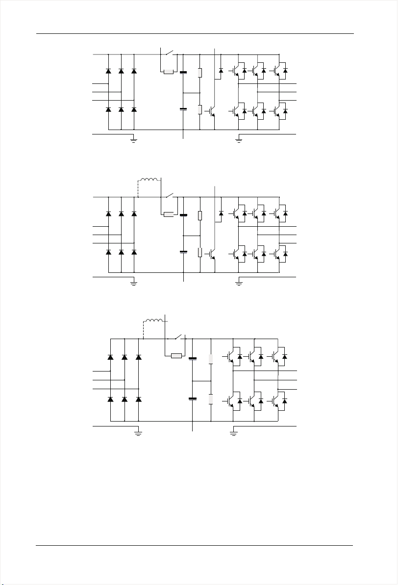
2.2 Basic Principle
SD300 i s a kind of A C drive u sed to co ntrol a synch ronous AC induct ion mot or.
The follo wing figu re s hows the AC drive mai n circuit d iagra m. R ectif ie m ake three -phas e
AC voltage i nto DC v oltag e. Capacitor grou ps of inte rmedi ate c ircui t sta biliz e the DC
volta ge .Th e AC dr ive converts o f the D C volt age to AC vol tage f or AC m otor u se. Wh en
the vol tage in the ci rcuit exceed s the m aximu m limit , the brakin g pipe wi ll co nnect an
exter nal bra king re sisto r to the in terme diate DC circuit to consu me the fe edbac k energ y.
-15-
Chapter 2 Product Information
SD300 User Manual
R
S
T
PE
P+
P-
PB
PE
Figur e 2-1 M ain Cir cui t Diagram( l ess t han 18. 5 kw (i ncluding ))
DC react or
R
S
T
PE
P+
P
P-
PB
PE
Figur e 2-2 M ain Cir cui t Diagram (2 2kw ~30kw )
DC reactor
P+
U
V
W
U
V
W
P
R
S
T
PE
P-
U
V
W
PE
Figur e 2-3 M ain Cir cui t Diagram (o ver 3 7kw)
Note:
Higher th an 2 2kw AC driv e (i ncluding ) su pport for exte rnal DC react or, b efore
1.
connecti ng, it need to take down t he br onze betwe en P an d P +. 1.
2. Low er than 30k w AC dri ve (inc luding) supp ort for ext ernal braking resis tor, hi gher
than 37kw AC d riv e (includi ng) s upport for exte rnal braking un it , br aking resi sto r.
-16-
SD300 User Manual
Chapter 2 Product Information
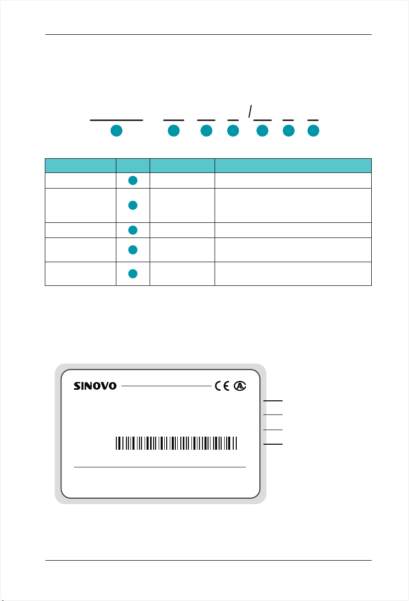
2.3 Naming Rules
In the mo del cod e conta ins the p roduc t information Users can find the c ode fro m the
trans ducer and sim ple nam eplat e.
SD300
Field Mark
Ac driv e ser ies
Volta ge Le vel
Adapt ive P ower
Funct ion T ype
braki ng Un it
1
1
2
3
4
5
4T
-
2 4
Explanation
Ac driv e ser ies
Volta ge Le vel
Adapt ive P ower
Funct ion T ype
braki ng Un it
Figur e 2-4 N ame Des ign ation Rule s
2.4 Nameplate
MODEL : SD300 -4T-5.5G/7.5P C
INPUT : AC3PH 3 80V 50/ 60Hz 14.6A/20.5A
OUTPU T: AC3P H 380V 0~600Hz 1 3A/17 A
S/N: FD LAGCA 0A040
SHENZHEN SINOVO ELECTRIC TECHNOLOGIES CO.,LTD.
G
11
3 3
Sinod riv e200 ab bre viated SD3 00
2S:si ngl e-pha se 22 0V
2T:Th ree -phas e 220 V
4T:Th ree -phas e 380 V
0.7KW ~50 0KW
G:Gen era l
P:Fan pum p
Null
C:
Only br aki ng unit
MADE IN CHINA
15
:None
C
P
5
4
Content
Model of the AC drive
Rated input voltage,
frequency and current
Rated output voltage,
frequency and current
Bar cod e
Figur e 2-4 N ame Des ign ation Rule s
-17-
Chapter 2 Product Information
2.5 SD300 Series of AC drive
SD300 User Manual
Model
SD 300 -2S -0. 7G
SD 300 - - 1.52S G
SD 300 - - 2.22S G
SD 300 -2T -0. 7G
SD 300 - - 1.52 T G
SD 300 - - 2.22 T G
SD 300 -4T -0. 7G
SD 300 -4T -1. 5G
SD 300 -4T -2. 2G
SD 300 -4T -4. 0G
SD 300 -4T -5. 5G
SD 300 -4T -7. 5G
SD 300 -4T -11 G
SD 300 -4T -15 G
SD 300 -4T -18 .5G
SD 300 -4T -22 G
SD 300 -4T -30 G
SD 300 -4T -37 G
SD 300 -4T -45 G
SD 300 -4T -55 G
SD 300 -4T -75 G
SD 300 -4T -90 G
SD 300 -4T -11 0G
SD 300 -4T -13 2G
SD 300 -4T -16 0G
SD 300 -4T -18 5G
SD 300 -4T -20 0G
SD 300 -4T -22 0G
SD 300 -4T -25 0G
SD 300 -4T -28 0G
SD 300 -4T -31 5G
Power Capacity
(KVA)
single-p hase 220V Ra nge:-15%~20 %
1. 5
3. 0
4. 0
Three-ph ase 220V Ran ge:-15%~20%
1. 5
3. 0
4. 0
Three-ph ase 380V Ran ge:-15%~20%
1. 5
3. 0
4. 0
5. 9
8. 9
11
17
21
24
30
40
57
69
85
11 4
13 4
16 0
19 2
23 1
25 5
28 7
31 1
35 5
39 6
43 9
Input Current
(A)
8. 2 0.7 54.7 0.7 5
14 .0 7.5
23 .0
5. 5 0.7 54.7 0.7 5
7. 7 7. 5
12 .0
3. 4 0. 752. 3 0. 75
5. 0 3. 7
5. 8
10 .5 8. 5 4. 0
14 .6 13
20 .5
26 .0 25 11
35 .0 32
38 .5 37 18 .5
46 .5 45
62 .5 60 3 0
76 .0
92 .0 91 4 5
11 3
15 7
18 0 176 90
21 4
25 6 253 13 2
30 7 304 16 0
33 3 330 18 5
38 0 377 20 0
42 9 426 220
47 0 465 25 0
52 5 520 28 0
60 5 600 31 5
Output Current
Adaptable Motor
(A)
10 .0
10 .0
5. 1
17 7. 5
75
11 2
15 0
21 0 11 0
(KW)
1. 5
2. 2
1. 5
2. 2
1. 5
2. 2
5. 5
15
22
37
55
75
-18-
SD300 User Manual
Chapter 2 Product Information
Model
SD 300 -4T -40 0G
SD 300 -4T -45 0G
SD 300 -4T -50 0G
Power Capacity
(KVA)
47 9
53 0
60 0
66 0
Input Current
(A)
66 5 660 35 0SD 300 -4T -35 0G
73 0 725 40 0
82 5 820 45 0
91 0 900 50 0
Output Current
(A)
Adaptable Motor
(KW)
Note:
1. 0.75 ~ 315 kw AC dri ve in put current is th e mea sured resu lts , which under the c ond ition
of input vol tag e 380V, and witho ut DC reactor as we ll as i npu t and output reac tor;
2. 350 ~ 500 kw AC driv e inp ut cu rrent is the meas ured resul ts, w hich under the co ndi tion
of input vol tag e 380V, and equip ped with input re act or;
3. Rated out put c urrent is defin ed as t he output curre nt of the output vo lta ge 380V.
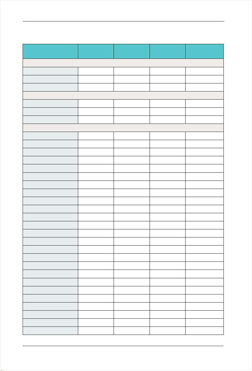
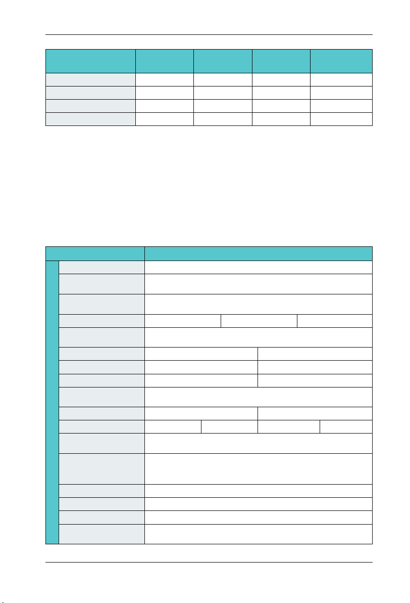
2.6 Technical Specifications
Item
Maximum frequency
Carrier frequency
Input frequency
resolution
Startup torque
Speed range
Speed stability accuracy
Basic Function
Torque control accuracy
Overload capacity
Torque boost
V/F curve
Accelerate/
Decelerate curve
DC braking
Jog contro l
Sim ple PLC Multi-speed
Onboard PI D
Auto voltage
regulation (AVR)
0~600Hz
1.0kHz~10kHz;The carrier frequency is automatically adjusted
based on the load features.
Digital setting:0.01Hz
Analog setting : Maximum frequency x 0.025%
G Type:0.5Hz/150%(SVC) 0Hz/180%(FVC)
P Type:0.5Hz/110%
G type:150% rated current for 60s
P type: 110% rated current for 60s
Line or S-curve Acc/Dec mode, four kinds of Acc/Dec time Range of
Acc/Dec time 0.0~6000.0s
DC braking frequency : 0.00Hz to Maximum frequency
braking time: 0.0 to 100.0s
braking current : 0.0 to 150%
Jog fre que ncy ran ge:0. 00Hz~Max imu m frequ enc y
16-speed o perating t hrough built- in PLC or cont rol terminal
It real ize s process-con troll ed cl osed loop co ntr ol syst em ea sily.
Jog fre que ncy ran ge:0. 00Hz~Max imu m frequ enc y
Specification
V/F
1:100(SVC)
±0.5%(SVC)
±10%(SVC)
Auto torque boost
Line
Multi-point
SVC FVC Control mode
1:1000(FVC)
±0.02%(FVC)
±5%(FVC)
Manual torque boost: 0.1%~20.0%
Square V/F curve
VF separation
-19-

Chapter 2 Product Information
SD300 User Manual
Item
Overvoltage/overc-
Function
Basic
urrent stall control
Rapid current limit
Torque control
High performance
Non stop function
Speed tracking start
Rapid current limit
Freatures
Virtual IO
Timing Control
Multi-motor switch
Bus Support
Motor overheating
protection
Multi-encoder
support
Command source
Frequency source
Auxiliary frequency
source
Input terminal
Running
Output terminal
Specification
The current and voltage are limited automatically during the running
process so as to avoid frequent tripping due to overvoltage/over-current.
It helps to av oid freque nt over- curren t faults of th e AC drive.
Open /c los ed-lo op ve ctor model c an re alize t orq ue control
High-performance current vector control technology to achieve a threephase AC induction motor control
Load feedback energy compens ates the voltage reduction so that the
AC drive can continue to r un in a short time in c ase of power interruption.
Identify the speed of rapidly rotating motor to realize a smooth start
without any rush.
Rapid software and hardware current limiting technology helps to avoid
frequent over-current fault.
Five sets of virtual DIDO enables easy logic control.
Timing control: set the time range 0.0Min~6500.0Min
Two independen t motor parameters enable two motors switching control
Two independent Modbus co mmunication, one CAN communication,
Profibus-DP
Optional IO expansion card 1, analog input AI3 acceptable the input of
motor temperature sensor .(PT100,PT1000)
Support differential, open colle ctor optical encoders, resolvers speed
sensor.
Given the control panel, control terminal, serial communication port
given. It can be switched by a variety of ways.
11 frequency sources: digital setting, analog voltage setting, analog current
setting, pulse setting and serial port. It can be switched by a variety of ways.
11 auxiliary frequency source. Flexible implementation of auxiliary
frequency tuning, frequency synthesis.
Standard:
. Six digital input terminals, one of which support to 50kHz high-speed
pulse input
. Three analog input terminals, two of which supports -10V~10V voltage
input
. One support 0 ~ 10V voltage input or 0 ~ 20mA current input Expansion
capability:
. Two digital inputs
. One analog input terminal, support -10V ~ 10V voltage input, and
supports PT100 / Pt1000
Standard:
. One high-speed pulse output terminal (optional open collector type),
support of 0 ~ 50kHz square wave signal output
. One digital output terminal
. Two relay output terminals
. Two analog output terminals, support 0~20mA current output or 0~10V
voltage output
Expansion capability:
. One digital output terminal
. One relay output terminal
. One analog output terminal, support 0~20mA current output or 0~10V
voltage output.
-20-

SD300 User Manual
Chapter 2 Product Information
Item
LED display
The key lock and
Display and
function selection
operation
Protection function
Accessories
Application
environment
Environment
Altitude
Ambient temperature
Humidity
Vibration
Storage temperature
Specification
Display each parameter of function code group
Achieve some or all of the keys locked and define the scope of partial
keys to prevent misuse.
Powered motor short circuit test; Input/output phase failure protection;
Over current protection; voltage protection; Under voltage protection;
Over heat protection ; Overload protection; braking resistor fault protection.
Braking assembly, simple IO expansion cards, multi-IO expansion card,
RS485 communication card, CAN communication card, differential input
PG card, resolver PG card, OC input PG card.
In-door, free from direct sunlight, dust, corrosive gas, combustible ga , oil
mist, steam , water drop and salt .
Lower than 1000m (1000m-3000m for derated use)
-10℃+40℃ (derated use in the ambient temperature of 40℃ to 50 ℃ )
Less than 95%RH, without condensation
Less than 5.9m/s(0.6g)
-20℃~+60℃
-21-
Chapter 2 Product Information
SD300 User Manual
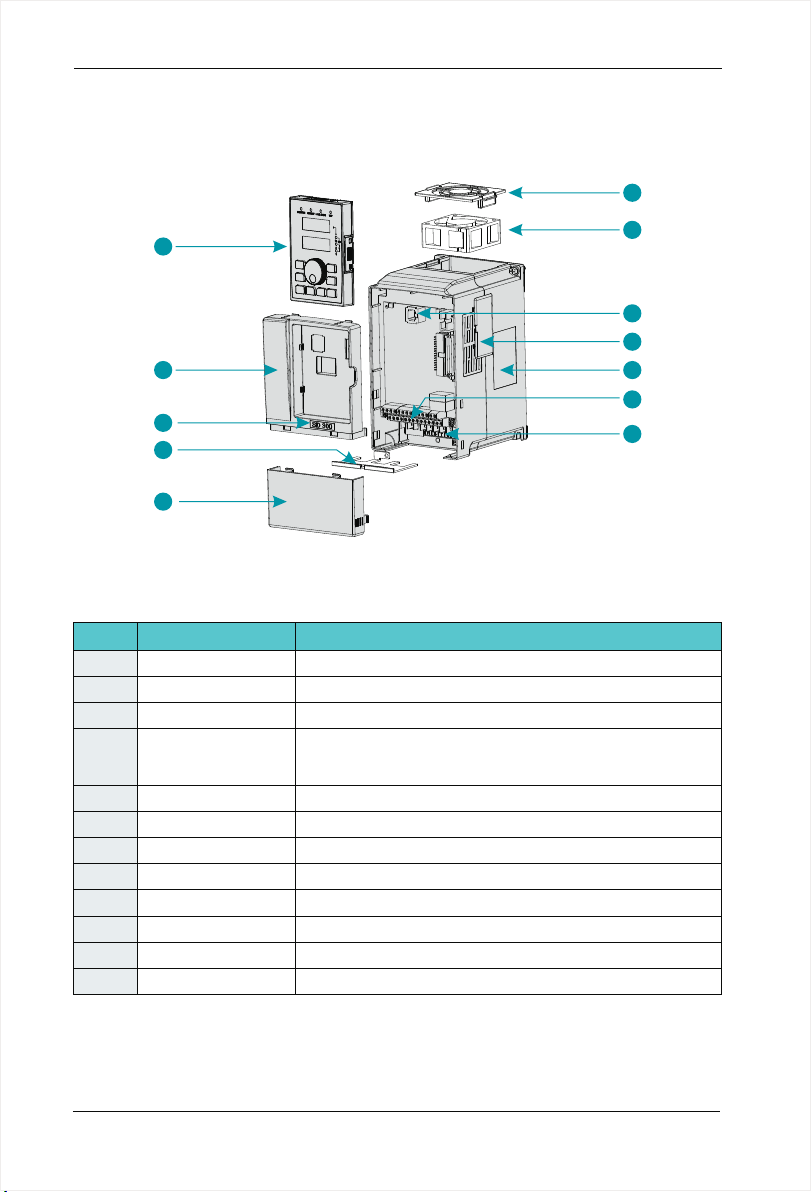
2.7 Structure diagram
2.7.1 The following figure shows the layout of the AC drive ( 7.5KW,for example).
1
8
9
10
11
12
No
1
2
3
4
5
6
7
8
9
10
11
12
Keypad interface
Control terminals
Main circuit terminals
Name
Fan-cover
Cooling fan
Vents-cover
Nameplate
Keypad
Cabinet-cover
Series Label
Apron
Lower-cover
2
3
4
5
6
7
Figur e 2-6 P roduc t str ucture dia gra m
Description
Protection fan.
Refer to 8.1 " Definition of Related Terms."
It is used to connect the Keypad.
Optional. with the vents-cover installed, the protection level will
increase and the AC drive internal temperature will increase as
well so please derating use the AC drive.
Refer to 2.4 "Nameplate"
Refer to 3.3 "Standard Wiring."
."
Refer to 3.3 "Standard Wiring."
Refer to chapter4 "Operation, Display and Application Examples."
Protect the internal components.
Refer to 2.3 "Naming Rules".
Convenient input and output wiring.
Protect the internal components.
-22-
SD300 User Manual
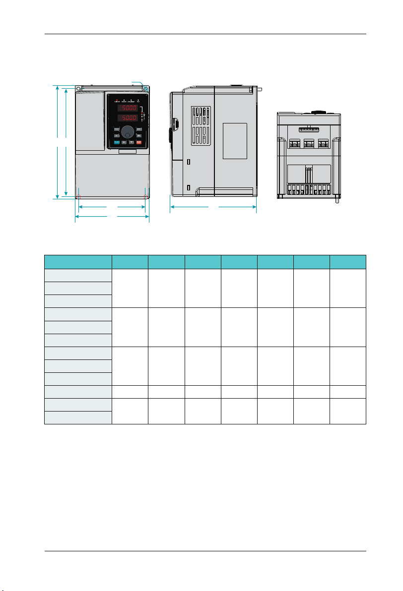
2.7.2 Product Outline, Installation Hole Size
2.7.2.1 SD300 series less than7.5KW (including 7.5KW)
Ø
H
H1
Chapter 2 Product Information
W1
W
D
Figur e 2-7 L ess tha n 7.5 K W AC drive ins tal latio n dim ensions an d ins talla tio n size
AC driv e mo del
H(mm) W(mm) D(mm)
H1(mm ) W1 (mm)
D
SD 300 -2S -0. 7G
SD 300 -2 -1 .5S G
19 0 11 0 15 0 17 8 98
SD 300 -2 -2 .2S G
SD 300 -2T -0. 7G
SD 300 -2T -1. 5G
19 0 11 0 15 0 17 8 98
SD 300 -2T -2. 2G
SD 300 -4T -0. 7G
SD 300 -4T -1. 5G
19 0 11 0 15 0 17 8 98
SD 300 -4T -2. 2G
SD 300 -4T -4. 0G
SD 300 -4T -5. 5G
SD 300 -4T -7. 5G
21 0 13 0 16 0 19 8 11 8
25 0
15 5
17 6 23 6
14 1
iameter
(mm)
Ø5
Ø5
Ø5
Ø5
Ø5
GW(kg)
2. 4
2. 4
2. 4
3. 5
4. 5
-23-
Chapter 2 Product Information
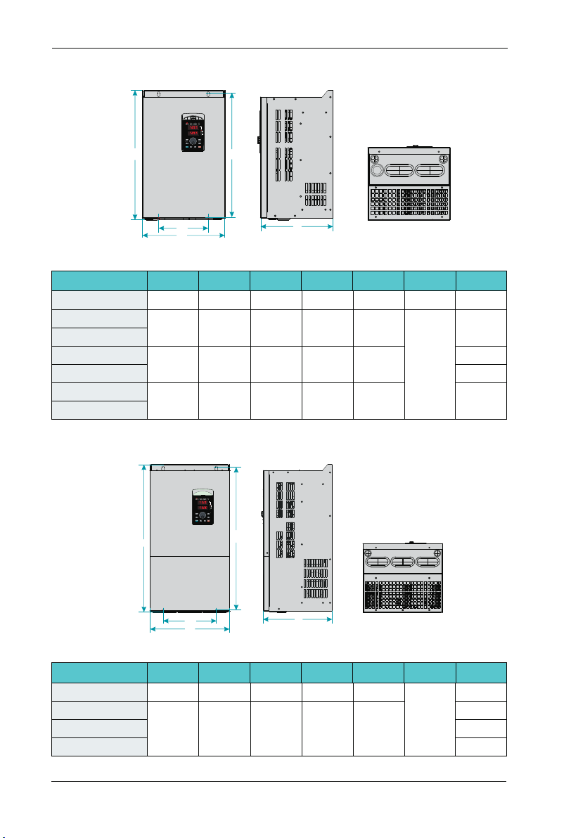
2.7.2.2 SD300 Series 11KW~45KW
SD300 User Manual
H
W1
W
Figur e 2-8 1 1kw~4 5kw A C drive inst all ation d ime nsion s and i nst allat ion s ize
AC driv e mo del
SD 300 -4T -11 G
SD 300 -4T -15 G
SD 300 -4T -18 .5G
SD 300 -4T -22 G
SD 300 -4T -30 G
SD 300 -4T -37 G
SD 300 -4T -45 G
H(mm) W(mm) D(mm)
28 5
33 2
38 7
17 0 16 2 27 0
22 0
25 0 22 0 37 3
27 0 25 2 42 6 2544 0
2.7.2.3 SD300 Series 55KW~110KW
H
H1
D
iameter
13 5
14 0
15 0
D
(mm)
Ø6
Ø7
GW(kg)
5. 1
9. 3
14
19
H1(mm ) W1 (mm)
21 4
31 8
18 0
H1
Fig 2-9 5 5~1 10KW AC d riv e installa tio n dimen sio ns and insta lla tion si ze
AC driv e mo del
SD 300 -4T -5 G5
SD 300 -4T -75 G
SD 300 -4T -90 G
SD 300 -4T -11 0G
W1
W
H(mm) W(mm) D(mm)
30 0 25 8 53 4 20 0
65 0
37 0 28 2 62 5 25 0
-24-
D
H1(mm ) W1 (mm)
D
iameter
(mm)
Ø9
GW(kg)
3255 0
52
55
58

SD300 User Manual
2.7.2.4 SD300 Series 132KW~185KW
H
H1
Chapter 2 Product Information
W1
W
D
Figur e 2-1 0 132KW ~18 5KW AC drive i nst allat ion d imension s and i nstal lat ion siz e
AC driv e mo del
H(mm) W(mm) D(mm)
H1(mm ) W1 (mm)
SD 300 -4T -13 2G
88 0 48 5 31 0 86 0 32 0
SD 300 -4T -18 5G
2.7.2.5 SD300 Series 200KW~500KW
H1
H
D
iameter
(mm)
Ø1 3
GW(kg)
99SD 300 -4T -16 0G
W1
W
D
Figur e 2-1 1 200KW ~50 0KW AC drive i nst allat ion d imension s and i nstal lat ion siz e
-25-
Chapter 2 Product Information
AC driv e mo del
H(mm) W(mm) D(mm)
SD 300 -4T -20 0G
SD 300 -4T -22 0G
12 50 50 0 40 0 100 0 440
SD 300 -4T -25 0G
SD 300 -4T -28 0G
SD 300 -4T -31 5G
13 50 65 0 40 0 110 5 513
SD 300 -4T -35 0G
SD 300 -4T -40 0G
SD 300 -4T -45 0G
18 10 85 0 40 5 141 0 513
SD 300 -4T -50 0G
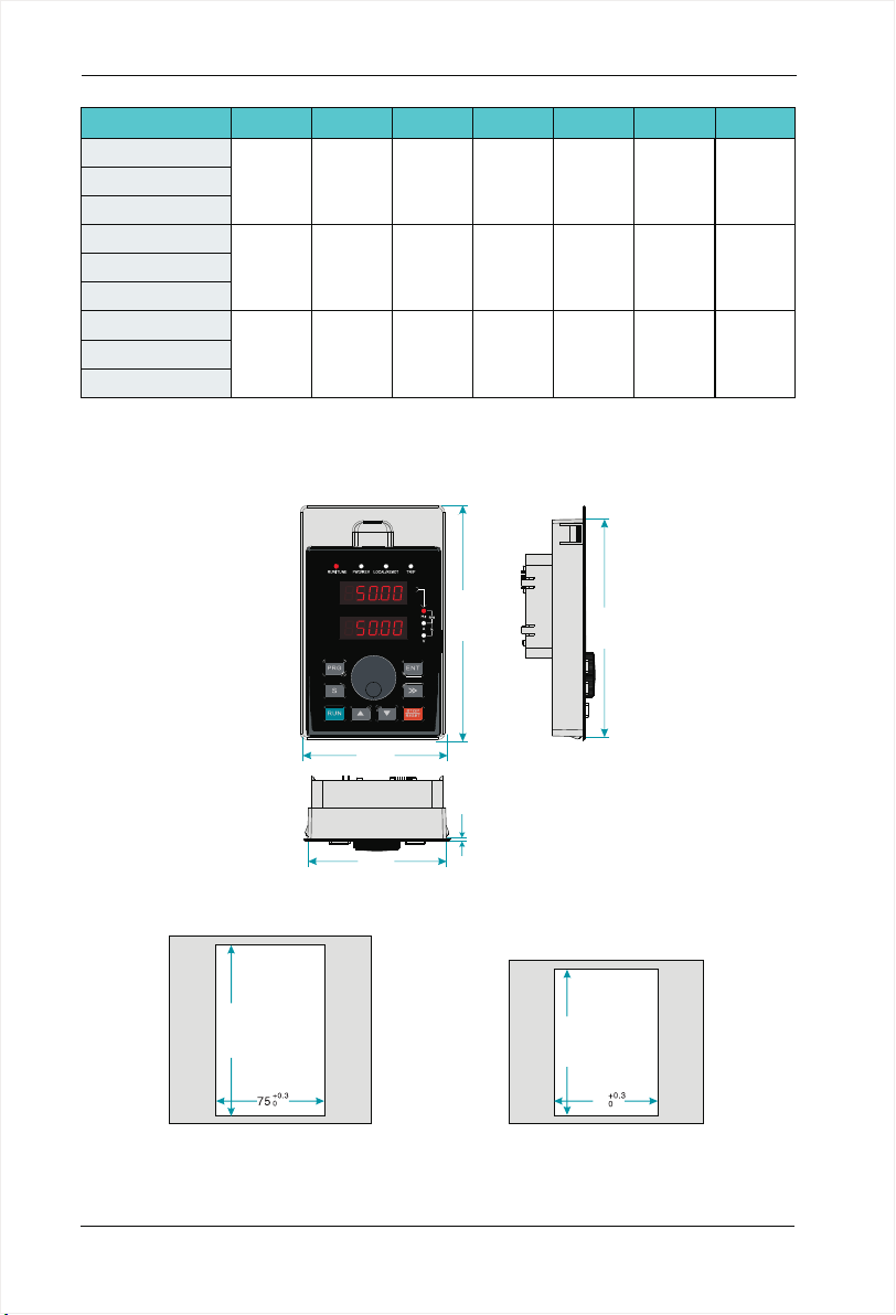
2.7.3 External Keypad Installation Dimensions
H1(mm ) W1 (mm)
SD300 User Manual
D
iameter
(mm)
Ø1 3
Ø1 3
Ø1 3
GW(kg)
16 7
20 6
41 5
79.00
74.80
Figur e 2-1 2 Keypa d Ins tallatio n dim ensio ns
+0. 3
0
119 .5
Figur e 2-1 3
Openi ng di mensi on di agram
for key pad w ith bas e
-26-
128.20
1.50
Openi ng di mensi on di agram
for key pad w ithou t bas e
119.00
+0. 3
0
100
70
Figur e 2-1 4
SD300 User Manual
Chapter 2 Product Information
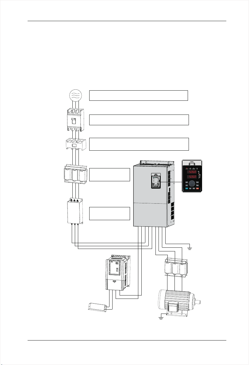
2.8 Peripheral Electrical Components System Structure
When usi ng SD300 serie s A C d rive t o c ontro l a synch ronou s moto r s ystem , you hav e t o
insta ll va rious elec trica l com ponents on the si de of inpu t and outp ut of the AC dr ive t o
guara ntee the stab ility and safe ty o f sy stem. In a dditi on, SD300 s eries A C drive is
equip ped w ith a va riety of o ption al accessories and expa nsion card to achi eve v ariou s
funct ions. Mor e th an 37kw ser ies three -phas e 38 0v syst em struct ure as show n in the
figur e below (The fi gure AC d rive te rminal refer to 55~110K W):
3-phas e AC
power su ppl y
Moulde d cas e
circui t bre ake ror
earth le aka ge
circui t bre ake rs
Electr oma gne tic
contac tor
AC re act or
Inp ut si de EM C
fil ter
Use with in th e all owa ble p ower supp ly sp eci fic ati on
of th e AC dr ive
Select a proper b reaker t o resistlarge in- rush cur rent
that fl ows into t he AC driv e at power-on
To guarantee sa fety, us e an electromagne tic cont actor.
Do not use it to star t or stop th e AC drive because su ch
operation red uces the s ervice life of the AC d rive
Suppress the hi gh
order harmoni c to
improve power f actor
AC Driver
Reduce the elec tromagnetic inter ferenc e
on the input side .
Bre ak un it
P
P+
R
P-
S
T
U
V
W
PE
Gro und
Out put r eac tor s
PB
P
P+
Brakin g res ist or
BR
P+
P-
Gro und
Motor
Figur e 2-1 5 Under 3 7 kw se ries 3-pha se 38 0 V syste m str ucture dia gra m
-27-

Chapter 2 Product Information
2.8.1 Peripheral Electrical Components Description
SD300 User Manual
Accessory
Name
MCCB
Conta ctor
AC input
reactor
EMC input
filter
DC reactor
AC output
reactor
Installation
position
Power
receiving side
Between MCCB
and the AC drive
input side
AC drive
input side
AC drive
input side
SD300 series
AC drive of
30G and above
configured
with DC reactor
as standard
Between the AC
drive output side
and the motor,
close to the AC
drive
Function Description
Inter rupt th e power s upply w hen ove rcurr ent occurs
ª
on down strea m devic es.
Start and stop the AC drive.Do not start and stop the AC
ª
drive frequently by switching the contactor on and off
(less than twice per minute) nor use it to directly start
the AC drive.
Improve the power factor of the input side;
ª
Eliminate the higher harmonics of the input side effecti-
ª
vely and prevent other devices from being damaged due
to distortion of the voltage waveform;
Eliminate the input current unbalance due to unbalance
ª
between the power phases;
Reduce the external conduction and radiation interfere-
ª
nce of the AC drive;
Decrease the conduction interference flowing from the
ª
power end to the AC drive and improve the anti-interfe rence capacity of the AC drive.
Improve the input power factor;
ª
Improve the efficiency and thermal stability of the AC
ª
drive;
Eliminate the impact of higher harmonics of the AC drive
ª
input side and reduce the external conduction and
radiation interference.
The output side of the AC drive generally has much
ª
higher harmonics. When the motor is far from the AC
drive, there is much distributed capacitance in the circuit
and certain harmonics may cause resonance in the
circuit, bringing about the following two impacts:
a.Degrade the motor insulation performance and damage
the motor in the long run.
b.Generate large leakage current and cause frequent AC
drive protection trips.
If the distance between the AC drive and the motor is
ª
greater than 100 m, install an AC output reactor.
-28-

SD300 User Manual
Chapter 2 Product Information
Note:
Do not install capacitor or surge su ppressor on the out put side of the AC drive.
1.
Otherwis e, it may ca use fa ults to the AC drive or damage to the capaci tor an d s urge
suppress or;
2. I nput/out put (main circ uit ) o f t he AC dri ve include har monic componen ts, which may
interfer e with the AC drive att achment commun ica tions equ ipment. Theref ore , inst all
an anti-al iasing filter t o min imize the inter ference;
3. Details o f per ipherals a nd op tions refer to Ch apt er 2 selecti on of p eripheral dev ices.
2.8.2 Peripheral electrical components selection guidance
AC Drive mod el
SD 300 -2S -0. 7G
SD 300 -2 -1 .5S G
SD 300 -2 -2 .2S G
SD 300 -2T -0. 7G
SD 300 -2T -1. 5G
SD 300 -2T -2. 2G
SD 300 -4T -0. 7G
SD 300 -4T -1. 5G
SD 300 -4T -2. 2G
SD 300 -4T -4. 0G
SD 300 -4T -5. 5G
SD 300 -4T -7. 5G
SD 300 -4T -11 G
SD 300 -4T -15 G
SD 300 -4T -18 .5G
SD 300 -4T -22 G
SD 300 -4T -30 G
SD 300 -4T -37 G
SD 300 -4T -45 G
SD 300 -4T -5 G5
MCCB(A)
Recommended
contactor
Recommended
input side main
circuit wire mm2
Recommended
output side main
circuit wire mm2
Single pha se 220V
16
20
32
16
25
25
10
16
20
Three phas e 220V
10
16
16
2. 5
4. 0
6. 0
2. 5
4. 0
4. 0
2. 5
2. 5
4. 0
2. 5
2. 5
4. 0
380VThree phas e
10
16
16
25 16 4. 0 4. 0 1.0
32 25 4. 0 4. 0 1.0
40 30 4. 0 6. 0 1.0
63
63
10 0
10 0
12 5
16 0
20 0
25 0
6
10
10
40
40
63
63
10 0
10 0
12 5
16 0
2. 5
2. 5
2. 5
4. 0
6. 0
10
16
16
25
50
2. 5
2. 5
2. 5
6. 0
10
6
10
10
16
25
25
35
Recommended
control loop
wire mm2
1. 0
1. 0
1. 0
1. 0
1. 0
1. 0
1. 0
1. 0
1. 0
1. 0
1. 0
1. 5
1. 5
1. 5
1. 5
1. 5
1. 5
-29-
 Loading...