

Sinovo SD200-4T-0.7G, SD200-2T-1.5G, SD200-2S-0.7G, SD200-2T-2.2G, SD200-2S-1.5G User Manual
...Page 1

Preface
SD200 User Manual
Preface
Thank you for purchasing the SD200 series AC drive developed by Our company.
SD200 series AC drive is a general-purpose high-performance vector control AC drive,
and it is mainly used for controlling and regulating the speed of the three-phase AC
asynchronous motor. It is a new generation of AC Drive with latest technology. SD200
series is characterized in the high-performance V/F control and Vector control 0
Algorithm technology, high torque output at low frequency and strong overload capacity.
It possess good stability, dynamic performance, communication bus functions, rich
powerful and stable performance, with perfect anti-tripping control and the ability to
adapt to bad power grid. It is used to drive various automatic produc tion equipments
involving the industry of textile, papermaking, wire drawing, machine tools, packa ging,
food, fans and pumps and so on.
SD200 Series AC drive Features
Advanced Vector Control Algorithm.
ªVector c on trol 0 Algori th m with low speed stability, high torque output a t low
frequency an d dy namic performance.
ªsmaller, com pa ct volume.
ªIn the full power range, the same power type compared to the old series products, it
reduces the volume of 20%~40%. As the vol ume is reduced, the optimized thermal
design ensur es t he favorable temperature rise of the whole AC drive.
ª485 Communication , externa l high precisi on PID, multi-stag e speed and simple PIC,
swing freque nc y, length and counting value functions.
Stronger functions:
Unpacking Inspection Cautions
The op timized VF control and sensorless vec to r control is more st ab le at low speed,
more powerful in the ability of low frequency torque output and w ith better dynamic
response and both the sensorless ve ctor and sensor vector mode support speed control
and torque con tr ol.
Every AC Drive have been tes te d strictly in factory prior to shipment. Upon u npacking,
check:
ªWhether the pr od uct is damaged;
ªWhether the na me plate of model and AC drive ratings are consistent with your order.
Page 2

-2 -
SD200 User Manual
Preface
First-time Use
For th e users who use this product for the first time, read the manual carefully. If in doubt
concerning some functi on s or performan ce s, co nt act t he tech ni cal s up port pe rsonnel of
Our company to e ns ure correct use.
SD200 series AC drives have passed CE test and also meet the requirements of following International Standard.
ªIEC/EN 6180 0- 5-1:2003 Sa fety re qu irements fo r adjus ta ble spe ed el ectric dr ive
systems.
ªIEC/EN 61800-3:2004 adjustable speed electric drive systems:(The third par)the
electromag ne tic compatibility standard of the product and its specific test method.
ªIEC/EN 610 00- 2-1 ,2-2,3-2,3 -3, 4-2 ,4-3,4- 4,4 -5, 4-6:EMC Intern ati onal an d EU
Standards.
The instruction s are subject to change, without notice , due to product upgrade,
specificat io n modification as well as efforts to increase the accuracy and convenience of
the manual.
ªWhether the box contains the AC drive, certificate of conformity, user manual and
warranty car d. I f you find any omission or damage, contact Our company or your supplier
immediatel y.
Page 3

Contents
SD200 User Manual
Contents
Preface.......................................................................................................................................01
Contents....................................................................................................................................03
Chapter 1 Safety and Cautions.........................................................................................07
1.1 Safety and Cautions De finition
1.2 Safety Cauti on s
1.3 Precautio ns
............ .. .. ........................................07
............ .. .. .............................................................08
............ .. .. ..................................................................10
Chapter 2 Product Information.........................................................................................15
2.1 Ch ap te r of This Content................................................ . ...............
2.2 Basic Principle............................................. .. ..............................
2.3 Naming Rules.................................................... .. .. .......................
2.4 Nameplate.................................................... .. .............................
2.5 SD200 Series of AC d rive.............................................................
2.6 Te ch nical Specifications......................................... .. .. ..................
2.7 Structure Diagram......................................... .. .. ...........................
2.8 Per ip heral Electrical Components System Structure............... .. .. .....
2.9 SD 20 0 Optional Parts................................................. .. .. ...............
2.10 Connection Methods............................................ .. .. ...................
. 15
15
17
17
18
19
22
27
29
31
Chapter 3 Mechanical and Electrical Installation........................................................33
3.1 Ch ap te r of This Content................................................ .. .. .............33
3.2 Mechanical Installation..................................... .. .. ........................34
3.3 Standard Wiring.................................................... .. .. ....................39
3.4 Layout Protection............................................. .. .. ........................49
Chapter 4 Operation, Display and Application Examples.........................................51
4.1 Ch ap te r of this Content............................... ............ .. .. ......51
4.2 Introduction of the Keypad............................................. .. .. ............52
4.3 D is play of Keypad.................................................. .. .. ...................54
4.4 Keypad Operation.................................................... .. .. .................55
............ .
Chapter 5 Function Parameter Table..............................................................................57
5.1 Ch ap te r of this Content.................................................. .. .. ............57
5.2 Fu nction Parameter Table....................................... .. .. ..................58
-3 -
Page 4

SD200 User Manual
Contents
-4 -
Chapter 6 Parameter Description.....................................................................................83
Group F00: Basic Func ti on Group........................... ............ .. .. ............84
Group F 01 : Start-stop Control Group.................................. .. .. ..............91
Group F 04 : V/Fcontrol Group......................................... .. .. ..................99
Group F05: Input T er minal Group..................................... .. .. ..............105
Group F06: Output Terminal Group......................................... .. .. ........113
Group F0 7: H MI Group..................................................... .. .. ..............119
Group F08: Strengthen th e Functional Groups................................. .. .. 125
Group F0 9: P ID Control Group............................................... .. .. .........132
Group F0A:Wobble, Length, Count and Ti mi ng Parameter Group..........142
Group F0B: Simple PLC and Multi-sp ee d Control Group....................... 14 5
Group F0C: Protection P arameter Group................................... .. .. ......149
Group F0D: Motor 2 Parameter Group....................................... .. .. ......154
Group F0E : Serial Communication Function Group...................... .. .. ....156
A01: A1 Curve Settin g Function Group...................................... .. .. ......159
A02: Stat us Check Function Group....................................... .. .. ..........161
..
Chapter 7 EMC.....................................................................................................................163
7.1 ............ .. .. .............................. ..........16 4
7.2 EMC Standard Introduction............................................. .. .. .........164
7.3 Selection of Peripheral EMC Devices................................... .. .. .....165
7.4 Shielded Cable.................................................. .. .. .....................169
7.5 Requ ir ement for Leakage Current........................................ .. .. .....171
7.6 Solutions to Common EMC Inter fe re nce Problems....................... .. 17 2
Definition o f Related Terms ..
Chapter 8 Troubleshooting and Maintenance...........................................................173
8.1 ...... .. ...... .. .. ..174
8.2 Warranty Agreement............................................ .. .. ...................175
8.3 Contents of This Chapter............................................ .. .. .............175
8.4 Al ar m and Fault Inductions........................................ .. .. ..............176
8.5 Fault Reset........................................................ .. .. .....................176
8.6 Fault History................................................... .. .. ........................176
8.7 Faul t Instruction and Solution........................................... .. .. ........176
8.8 C ommon Fault Analysis............................................ .. .. ...............181
Daily Re pa ir a nd Maintenance ............ .. .. ................ ..
Page 5

Chapter 9 Communication Protocol.............................................................................187
9.1 Networking Mode.................................................. .. .. ...... ......187
9.2 Interface Mode................................................ .. .. .......................188
9.3 Protocol Fram e Format............................................. .. .. ...............188
9.4 Fu nction Protocol.................................................. .. .. ..................189
9.5 Communication P ar ameters Address................................ .. .. ........192
......
SD200 User Manual
Contents
-5 -
Page 6

Page 7
Chapter 1
Safety and Cautions
1.1 Safety and Cautions Definition
Read this manual carefully so that you have a thorough understanding. Installat io n,
commission in g or maintenance ma y be performed in conjunction with this chapter. Our
company will assume no ability an d responsibility for any in ju ry or loss caused by
improper ope ra tion.
Danger
Note
Operations which are not performed comply with the requirements may cause severe
hurt or even dea th .
Operations which are not perf or med comply with requirements may caus e personal
injury or prop er ty damage.
-7 -
Page 8

SD200 User Manual
Chapter 1 Safety and Cautions
-8 -
1.2 Safety Cautions
1
Use Stage Safety Grade
Precautions
Danger
Before
Installati on
Do not install t he e quipment if you find water seepage,
ª
component mi ss ing or damage upon unpacking.
Do not install t he e quipment if the packing list does not
ª
conform to the p ro duct you received.
Danger
Handle the e qu ip ment with care during transportation
ª
to prevent dam ag e to the equipment.
Do not use the equ ip ment if any component is damaged
ª
or missing. Fa il ure to comply will result in personal
injury.
Do not touch the c om ponents with your hands. Failure
ª
to comply will r es ult in static electricity damage.
Danger
During
Installati on
Install the eq ui pment on incombustible objects such as
ª
metal, and kee p it a way from combustible materials.
Failures to co mp ly may result in a fire.
Do not loosen th e fi xed screws of the components,
ª
especial ly t he s crews withe red marks.
Do not drop wire e nd o r screw into the AC drive. Failure
ª
it will result i n da mage to the AC drive.
Install the AC d ri ve in places free of vibration and direct
ª
sunlight.
When two AC driv es a re laid in the same cabinet
ª
,arrange the i ns tallation positions properly to ensure
the cooling ef fe ct.
Danger
At wiring
A circuit brea ke r must be used to isolate the power
ª
supply and the A C dr ive. Failure to comply may result a
fire.
Ensure that th e po wer supply is cut off before wiring.
ª
Failure to com pl y may result in electric shock.
Never connec t th e power cables to the output
ª
terminals( U, V,W) of the AC drive. Pay attention to the
marks of the wir in g terminals and ensure correct
wiring. Fail ur e to comply may result in damage to the
AC drive.
Ensure that th e ma in cable line comply with the
ª
standard, th e li ne meets the EMC requirements and
the area safet y st andard. Failure to comply may result
in risk or accid en t.
Never connec t th e power cables the braking resistor
ª
between the DC b us t erminals P+, P-. Failure to
comply may res ul t in a fire.
Note
Page 9
1
-9 -
SD200 User Manual
Chapter 1 Safety and Cautions
Use Stage Safety Grade
Precautions
Danger
At wiring
Use a shield ed c ab le for the encoder, and ensure that
ª
the shieldin g la yer is reliably grounded.
Danger
Before
Power-on
Please confi rm t he peripheral equipment and cable
ª
converter is c on figured in this manual of the
recommende d mo del, all the configuration line in
accordance w it h the connection method of the manual
provides the c or rect wiring. Failure to comply will result
in acciden ts .
Check that the v ol tage class of the power supply is
ª
consistent w it h the rated voltage class of the AC drive.
Danger
After
Power-on
Do not open the AC d ri ve’s cover after power-on.
ª
Failure to com pl y may result in electric shock.
Do not touch the o pe ration of AC drive during the
ª
hands is wet. Fa il ure to comply will result in accident.
Do not touch any I /O t er minal of the AC drive. Failure
ª
to comply may re su lt in electric shock.
Do not change th e de fault settings of the AC drive.
ª
Failure to com pl y will result in damage to the AC drive.
Do not touch the r ot ating part of the motor during the
ª
motor auto-t un ing or running. Failure to comply will
result in acci de nt.
Danger
During
Operation
Signal detec ti on must be performed only by qualified
ª
personnel du ri ng operation. Failure to comply will
result in pers on al injury or damage to the AC drive.
Do not touch the f an o r th e discharging resistor to
ª
check the temp er ature. Failure to comply will result in
personal bur nt .
Danger
Avoid obje ct s fa lling into the AC drive when it is
ª
running. Fai lu re to comply will result in damage to the
AC drive.
Do not start or st op t he A C drive by turning the
ª
contactor ON /O FF . Failure to comply will result in
damage to the AC d ri ve.
Danger
After
Power-on
Do not repair or m ai ntain the AC drive at power-on.
ª
Failure to com pl y will result in electric shock.
Ensure that th e AC d rive is disconnected from all
ª
power suppli er s before staring repair or maintenance
on the AC drive.
Repair or main te nance of the AC drive may be
ª
performed on ly b y qualified personnel. Failure to
comply will re su lt in personal injury or damage to the
AC drive.
Page 10
Danger
After
Power-on
Set and check th e pa rameters again after the AC drive
ª
is replaced.
Use Stage Safety Grade
Precautions
SD200 User Manual
Chapter 1 Safety and Cautions
-1 0-
1
1.3 Cautions
1.3.1 Requirement on Residual Current Device(RCD)
The AC drive generates high leakage current d uring running, which f lows earthing (PE)
conductor. Thus i nstall a type-B RCD at the transient and steady-state leakage current
to ground that may be generated at st artup and during running of the AC dri ve . You can
select a special iz ed RCD with the function of suppre ss in g high harmonics o r general-
purpose RCD wi th r elatively large residual current.
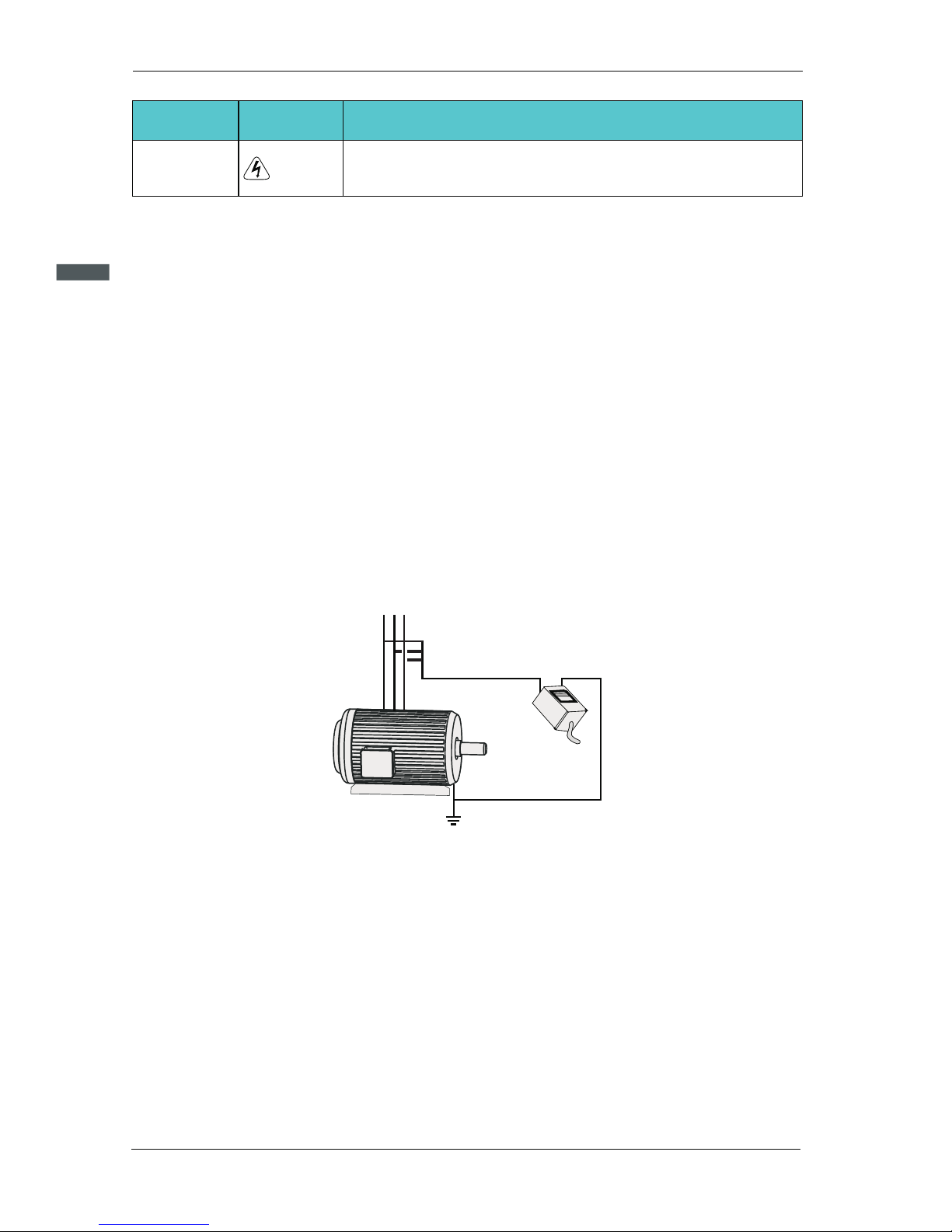
1.3.2 Motor Insulation Test
Perform the insulation test when the motor is used for the first time, or when i t is reused
after being stored for a long time, o r in a regular check-up, i n order to prevent the p oo r
insulation of motor wind in gs from damaging the AC drive during the insulatio n test. A
500-V mega-Ohm meter is recommended for the test. The insula ti on resistance must not
be less than 5 MΩ.
UVW
Input terminals of the motor
Megger
Ground
1.3.3 Thermal Protection of Motort
If the selected AC drive doe s not match the rated capacity of the motor , especially when
the ra te d power of the AC drive is higher than that of the motor, adjust the parameters for
motor protec ti on in the AC drive or to install thermal relay to protect the motor .
1.3.4 Running Below and Above Rated Frequency
The AC drive provides frequency output of 0 to 60 0.00Hz. When th e users use the
frequency converter for a long time, please pay attention to the motor cooling o r use o f
variable fr eq ue ncy motor. If the AC drive is required to run at over 50Hz, consid er th e
capacity of th e ma chine.
Page 11

1
-1 1-
SD200 User Manual
Chapter 1 Safety and Cautions
1.3.5 Vibration of mechanical device
The AC drive may e nc ounter the mechanical resonance point at some output frequencies,
which can be avo id ed by setting the skip frequency. If the operating frequency of the cus-
tomer coinci de w ith the resonant frequency please modify the operating frequency or
change the inh er ent resonance frequency of the mechanical system.
1.3.6 Motor heat and noise
The output of th e AC drive is pulse width modulation (PWM) wav e with certain harmonic
frequencie s, and therefore, the motor temperature, noise, and vibration are sli ghtly
greater than t ho se when the AC drive runs at power frequency (50 Hz).
1.3.7 Voltage-sensitive device or capacitor on output side of the AC drive
Do not install t he c apacitor for improving power factor or lightning protection voltagesen-
sitive resistor on the output side of th e AC dr ive because the output of the AC drive is
PWM wave. Otherwise, the AC drive may suffer tr ansient overcurrent o r even
bedamage d.
1.3.8 Contactor at the I/O terminal of the AC drive
When a contactor is installed between t he input side of the AC drive and the power
supply, the AC dri ve must not be started or stopped by switching the contactor on or off.
If the AC driv e has to be operated by the contactor, ensure that the time interval betw ee n
switching is at le as t one hour since frequent charge and discharge will shorten the
service life o f th e capacitor inside the AC drive.
When a contactor is i ns talled between the o ut put side of the AC drive and the motor,do
not turn off the contactor when the AC drive is active. Otherwise, modules inside the AC
drive may be dam ag ed.
M
U V
W
AC Driver
Capacitor or
voltage-sensitive resistor
Page 12

SD200 User Manual
Chapter 1 Safety and Cautions
-1 2-
1
M
380Vac
50/60Hz
R
S
T
U
V
W
Contactor KM
Do not start/stop the AC drive by
switching the contactor on/off. If
the AC drive has to be operated
by the contactor, ensure that the
tiome interval is at least one hour.
Contactor KM or
offer switches
AC Driver
Turn on /off the contactor when
the AC drive has no output.
Otherwise,modifies inside the AC
drive may be damaged.
1.3.9 The Use Occasion of the External Voltage Out of Rated Voltage Rage
The AC drive must not be used outside the allowable voltage range specified in th is
manual. Otherwise, the AC drive’s components may be damaged . If required, use a
correspond in g voltage step[-up or step-down device.
1.3.10 The Above Derating of the Default
Different power grade frequenc y converter has its default carrier frequenc y, when to
run at a higher ca rr ier frequency, the AC Drive must to reduce the amount when running.
1.3.11 Change Three Phase Input into Two Phase Input
It is not allowed to change the three ph as e AC drive into two phase one . O th er wise , it
may cause it may c au se fault or damage the AC drive.
1.3.12 The Protection of the Lighting Impulse
Although the AC drive has equipped with lightning overvoltage, overcurrent device, which
has a certain protection function for the induction lightining. For the lightning prone areas,
the user is necessary to install lightning protection device at the front of the AC drive,
which will benefit to the service life of the transducer.
1.3.13 Ambient Temperature and De-rating
The nor mal use o f the fre quency con verter amb ient te mpe rature is -10℃~40 ℃.
Tempe rat ure exce eds 40℃, the e quipment ne ed t o reduce t he a mou nt o f use. The
ambie nt tem perature of e ach inc rease is reduced by 1.5%, the maximum use of the
ambie nt te mperatur e is 50 ℃.
1.3.14 Altitude and Derating
In places where the altitude is a bove 1000m an d the c ool ing e ffe ct re duces due to th in
airit is necessary to de-rat e the AC d rive. Contact Our company for t echnical supp ort .
1.3.15 Some Special Usages
If writing that is n ot de scribed in th is ma nual, su ch as comm on DC bus is ap plied, cont-
act the agent o r Our comp any f or te chn ical support.
Page 13

SD200 User Manual
Chapter 1 Safety and Cautions
1.3.16 The Cautious of the AC drive Disposal
The electrolytic capacitors on the main circuits and PCB may explore when they are burnt.
Poisonous gas is generated when the plastic parts are burn. Treat them as ordinary indu-
strial refer to relevant national laws and regulations.
1.3.17 Adaptable Motor
1. The standard parameters of the adaptable motor is adaptable four-squirrel-cage
asynchronous induction motor or PMSM. For other types of motor, select a proper AC
drive according to the rated motor current.
2. The cooling fan and rotor shaft of general AC Drive are coaxial, which results in
reduced cooling effect when the rotational speed declines. If variable speed is
required, add a more powerful fan or replace.
3. The standard parameters of the adaptable motor have been configured inside the AC
drive. It is still necessary to perform motor auto-tuning or modify the default values
based on actual conditions. Otherwise, the running result and protection performance
will be affected.
4. The AC drive may alarm or even be damaged when short-circuit exists on cables or
inside the motor. Therefore, perform insulation short-circuit test when the motor and
cables are newly installed or during routine maintenance. During the test, make sure
that the AC drive is disconnected from the tested parts.
1
-1 3-
Page 14

Page 15

Chapter 2
Product Information
2.1 Chapter of This Content
This chapter b ri efly introduces the operation principle, product features, layout, namepl -
ate, and type of i ns tr uction.
2.2 Basic Principle
SD200 is a kind of A C dr ive used to control asynchronous AC induction motor.
The following figure shows the AC drive main circuit diagram. R ec ti fie make th ree-phase
AC v ol ta ge into DC voltage. Capacitor groups of i nt ermediate circuit stabilize the D C
voltage . Th e AC drive converts of the DC voltage to AC voltage for AC mot or use. When
the voltage in the circuit e xceeds the maxi mu m limit, the braking pipe will connect an
external bra ki ng resistor to the intermediate DC circuit to consume the feedback energy.
-1 5-
Page 16

Figure 2-1 Main Circu it Diagram( less than 1 8.5 kw (including))
P+
R
S
T
U
V
W
PE
PE
PB
P-
Figure 2-2 Main Circu it Diagram (22kw~30 kw)
R
S
T
U
V
W
PE
PE
PB
P-
DC reactor
P
P+
Figure 2-3 Main Circu it Diagram (over 30kw )
DC reactor
P
R
S
T
U
V
W
PE
PE
P+
P-
2
SD200 User Manual
Chapter 2 Product Information
-1 6-
Note:
1.
connecting, it need to take down the bronze between P and P +. 1.
2. Lower than 30kw AC drive (including) support for external braking resistor, higher
than 37kw AC drive (including) support for external braking unit , braking resistor.
Higher than 22kw AC drive (including) support for external DC reactor, before
Page 17
2
SD200 User Manual
Chapter 2 Product Information
-1 7-
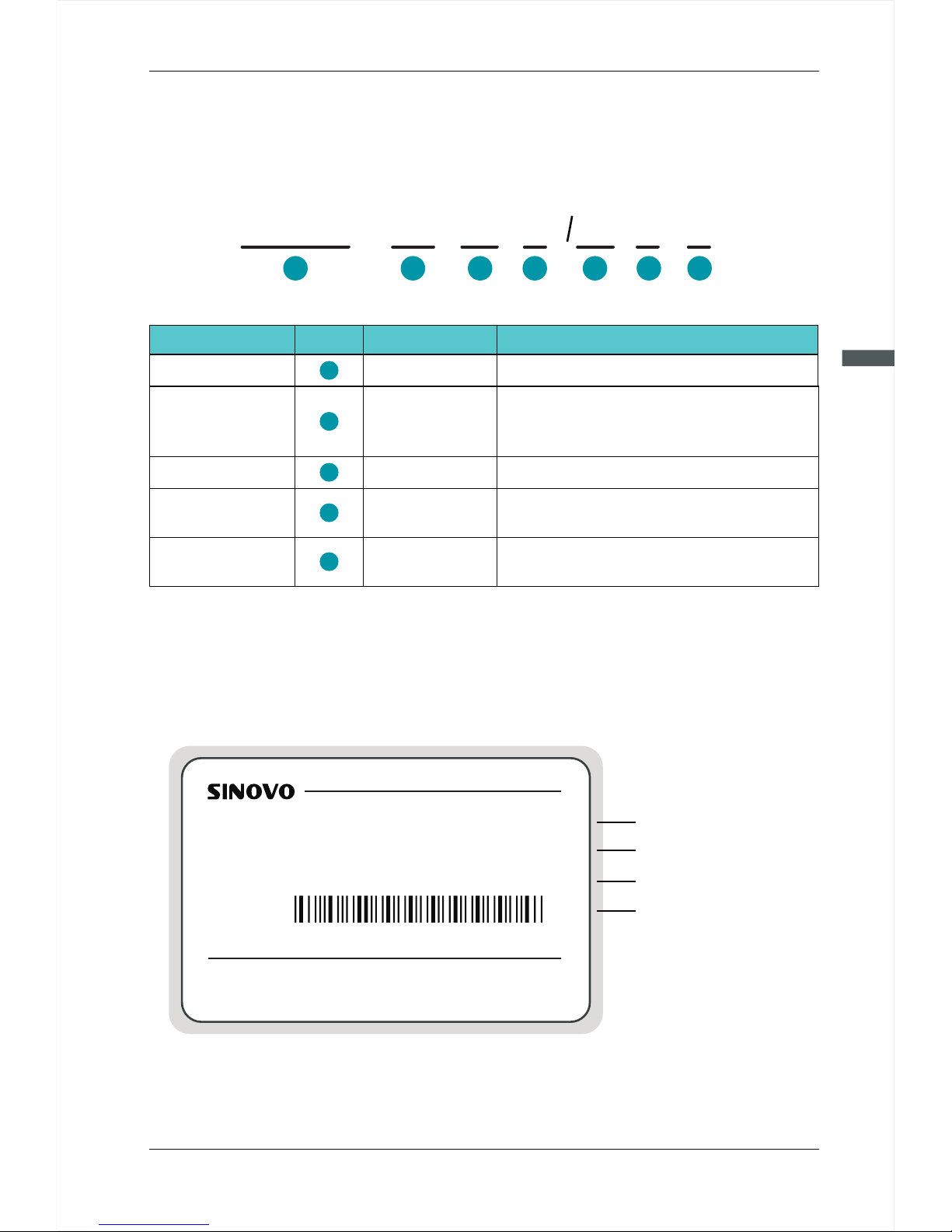
2.3 Naming Rules
In the model cod e co ntains the product information Users can find the code from the
transducer an d simple nameplate.
-
SD200
4T
11
G
P
15
1
2 4
5
C
3 3
4
Field M ark
Content
Explanation
Sinodrive200 abbr eviated SD200
Ac drive series
2S:single-phase 2 20V
2T:Three-phase 22 0V
4T:Three-phase 38 0V
Voltage Level
Adaptive Power
Null
C:
:None
Only braking unit
braking Unit
0.7KW~500KW
G:General
P:Fan pump
Function Type
Ac drive series
Voltage Level
Adaptive Pow er
braking Unit
Function Type
2
4
3
5
1
Figure 2-4 Name Desig nation Rules
Figure 2-4 Name Desig nation Rules
2.4 Nameplate
SHENZHEN SINOVO ELECTRIC TECHNOLOGIES CO.,LTD.
MODEL: SD200-4T-5.5G/7.5P C
INPUT: AC3PH 380V 50/60Hz 14.6A/20.5A
OUTPUT: AC3PH 380V 0~600Hz 13A/17A
S/N: FDLAGCA0A040
MADE IN CHI NA
Model of the AC drive
Rated input voltage,
frequency and current
Bar code
Rated output voltage,
frequency and current
Page 18
2
SD200 User Manual
Chapter 2 Product Information
-1 8-
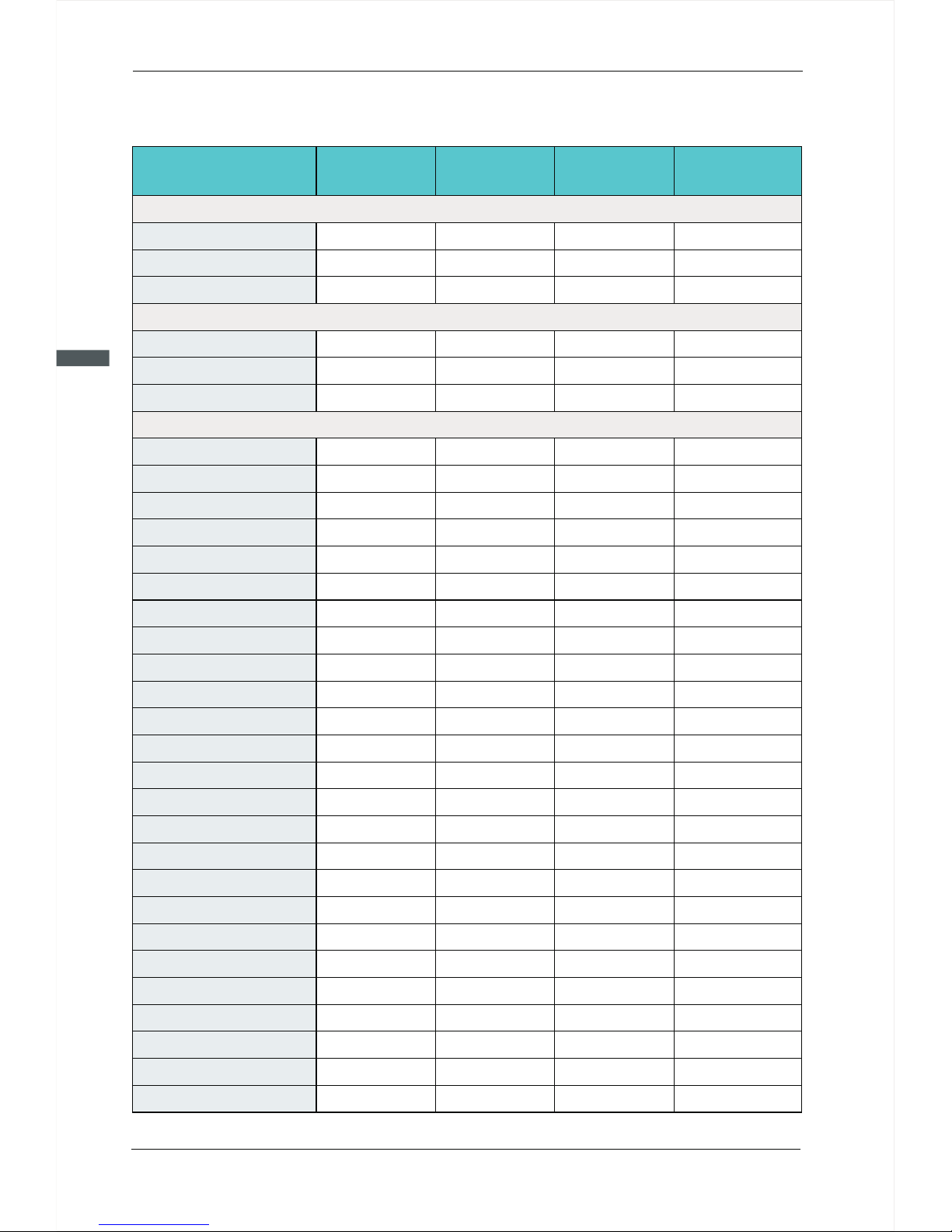
2.5 SD200 Series of AC drive
Model
Power Capacity
(KVA)
1. 5
Input Current
(A)
Output Current
(A)
Adaptable Motor
(KW)
3. 4 0. 752. 3 0. 75
Three-phase 380V Range:-15%~20%
3. 0
4. 0
5. 9
8. 9
11
40
57
69
85
11 4
13 4
16 0
19 2
17
21
24
30
23 1
35 5
25 5
39 6
28 7
43 9
31 1
5. 0 3. 7
1. 5
5. 8
5. 1
2. 2
10 .5 8. 5 4. 0
14 .6 13
5. 5
20 .5
17 7. 5
62 .5 60 30
76 .0
75
37
92 .0 91 45
11 3
11 2
55
15 7
15 0
75
18 0 176 90
21 4
21 0 110
25 6 253 1 32
26 .0 25 11
35 .0 32
15
38 .5 37 18.5
46 .5 45
22
30 7 304 16 0
47 0 465 25 0
33 3 330 18 5
52 5 520 28 0
38 0 377 20 0
60 5 600 31 5
42 9 426 220
SD 200-4 T-55G
SD 200-4 T-75G
SD 200-4 T-90G
SD 200-4 T-110G
SD 200-4 T-132G
SD 200-4 T-160G
SD 200-4 T-185G
SD 200-4 T-200G
SD 200-4 T-220G
SD 200-4 T-250G
SD 200-4 T-280G
SD 200-4 T-315G
SD 200-4 T-0.7G
SD 200-4 T-1.5G
SD 200-4 T-2.2G
SD 200-4 T-4.0G
SD 200-4 T-5.5G
SD 200-4 T-7.5G
SD 200-4 T-11G
SD 200-4 T-15G
SD 200-4 T-18.5G
SD 200-4 T-22G
SD 200-4 T-30G
SD 200-4 T-37G
SD 200-4 T-45G
1. 5
8. 2 0.754.7 0.75
single-phase 220V Range:-15%~20%
3. 0
4. 0
14 .0 7.5
1. 5
23 .0
10 .0
2. 2
SD 200-2 S-0.7G
SD 200- -1 .52S G
SD 200- -2 .22S G
1. 5
5. 5 0.754.7 0.75
Three-phase 220V Range:-15%~20%
3. 0
4. 0
7. 7 7. 5
1. 5
12 .0
10 .0
2. 2
SD 200-2 T-0.7G
SD 200- -1. 52T G
SD 200- -2. 22T G
Page 19
2
SD200 User Manual
Chapter 2 Product Information
-1 9-
53 0
60 0
66 0
47 9
73 0 725 40 0
82 5 820 45 0
91 0 900 50 0
66 5 660 35 0SD 200-4 T-350G
SD 200-4 T-400G
SD 200-4 T-450G
SD 200-4 T-500G
Model
Power Capacit
(KVA)
Input Current
(A)
Output Current
(A)
Adaptable Motor
(KW)
Note:
1. 0.75 ~ 315 kw AC drive input current is the measured results, which under the condition
of input voltage 380V, and without DC reactor as well as input and output reactor;
2. 350 ~ 500 kw AC drive input current is the measured results, which under the condition
of input voltage 380V, and equipped with input reactor;
3. Rated output current is defined as the output current of the output voltage 380V.
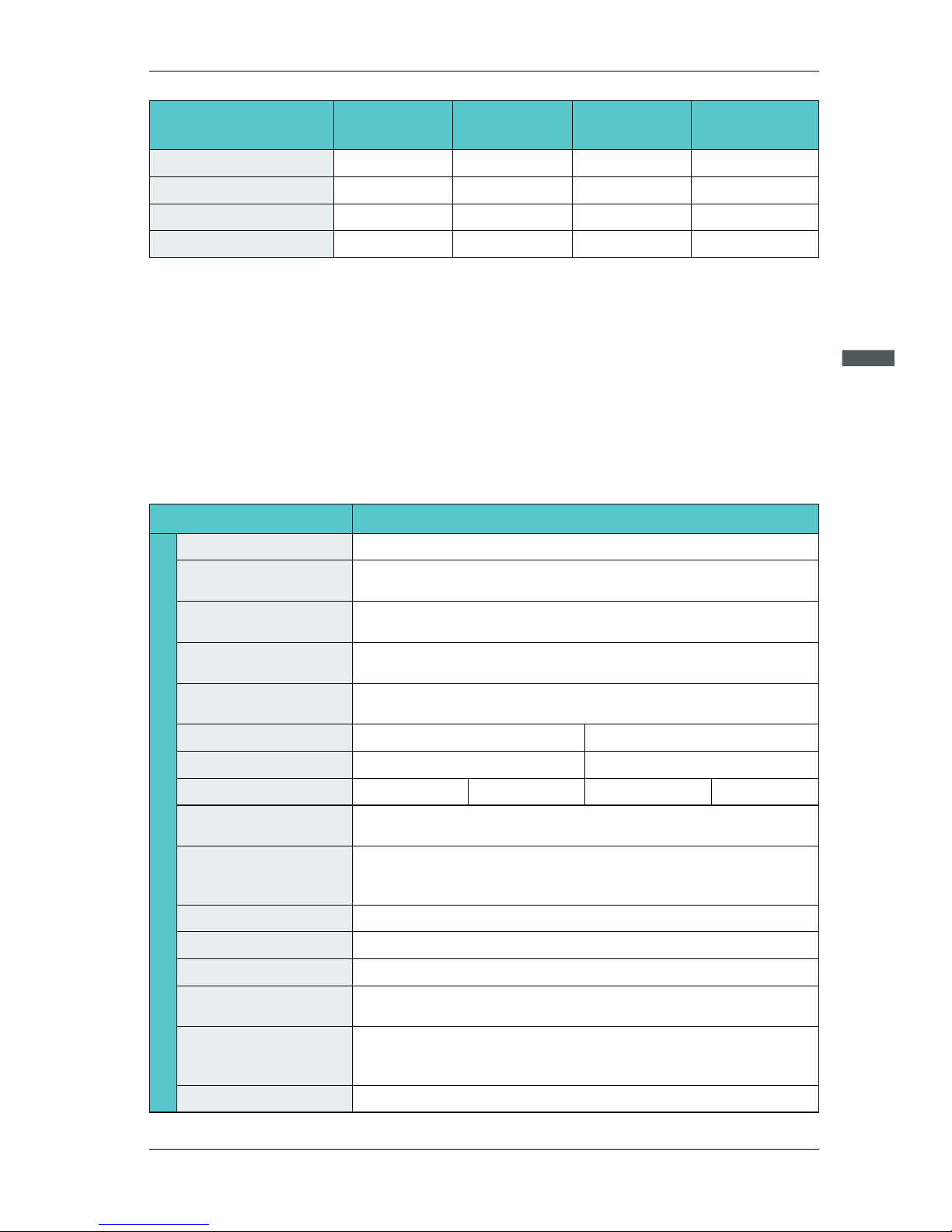
2.6 Technical Specifications
Item
Specification
0~600Hz
2.0kHz~10kHz; The carrier frequency is automatically adjusted
based on the load features.
1:50(vector control 0 mode)
1HZ/150% Rated troque
G type:150% rated current for 60s
Auto torque boost
Line or S-curve Acc/Dec mode, four kinds of Acc/Dec time Range of
Acc/Dec time 0.0~6000.0s
DC braking frequency : 0.00Hz to Maximum frequency
braking time: 0.0 to 100.0s
braking current : 0.0 to 150%
16-speed operatin g through built-in PL C or control terminal
It realizes proce ss-controlled clo sed loop control syst em e asily.
Jog frequency range:0 .00Hz~Maximum fre quency
The current and voltage are limited automatically during
the running process so as to avoid frequent tripping due to
overvoltage/overcurrent.
It helps to avoid frequ ent over- current fau lts of the AC drive.
P type: 110% rated current for 60s
Manual torque boost: 0.1%~20.0%
Maximum frequency
Carrier frequency
Input frequency
resolution
Overload capacity
Torque boost
V/F curve
Accelerate/
Decelerate curve
DC braking
Simple PLC Multi-speed
Onboard PID
Auto voltage
regulation (AVR)
Overvoltage/overcurrent
stall control
Rapid current limit
Jog frequency range:0 .00Hz~F00.03Max imum frequency
Jog control
Digital setting:0.01Hz
Analog setting : Maximum frequency x 0.025%
Basic Function
0:V/F control
1:Vector control 0 mode
Control mode
Speed range
Line
Multi-point
Square V/F curve
VF separation
Page 20

2
SD200 User Manual
Chapter 2 Product Information
-2 0-
Item
Specification
Freatures
Identify the speed of rapidly rotating motor to realize a smooth start
without any rush.
Load feedback energy compensates the voltage reduction so that
the AC drive can continue to run in a short time in case of power
interruption.
Speed tracking start
Non stop function
Rapid software and hardware current limiting technology helps to
avoid frequent over-current fault.
Rapid current limit
Four sets of virtual DO, five groups of virtual DI, enables easy logic
control.
Virtual IO
Timing Control
Two independent motor parameters enable two motors switching
control
Multi-motor switch
Timing control: set the time range 0.0Min~6500.0Min
Bus Support
Two independent Modbus communication, profibus-DP
Optional IO expansion card 1, analog input AI5 acceptable the input
of motor temperature sensor .(PT100,PT1000)
Motor overheating
protection
Running
Given the control panel, control terminal, serial communication port
given. It can be switched by a variety of ways.
Frequency source
Command source
11 frequency sources: digital setting, analog voltage setting, analog
current setting, pulse setting and serial port. It can be switched by a
variety of ways.
11 auxiliary frequency source. Flexible implementation of auxiliary
frequency tuning, frequency synthesis.
Auxiliary frequency
source
Standard:
. Six digital input terminals, one of which support to 50kHz high speed pulse input
. Three analog input terminals, two of which supports -10V~10V
voltage input
. One support 0 ~ 10V voltage input or 0 ~ 20mA current input
Expansion capability:
. Two digital inputs
. One analog input terminal, support -10V ~ 10V voltage input, and
supports PT100 / Pt1000
Input terminal
Standard:
. One high-speed pulse output terminal (optional open collector
type), support of 0 ~ 50kHz square wave signal output
. One digital output terminal
. Two relay output terminals
. Two analog output terminals, support 0~20mA current output or
0~10V voltage output
Expansion capability:
. One digital output terminal
. One relay output terminal
. One analog output terminal, support 0~20mA current output or
0~10V voltage output.
Output terminal
Display each parameter of function code group
LED display
Achieve some or all of the keys locked and define the scope of
partial keys to prevent misuse.
The key lock and
function selection
Display and
operation
Protection function
Powered motor short circuit test; Input/output phase failure protection; Over current protection; voltage protection; Under voltage protection; Over heat protection ; Overload protection; braking resis-
Page 21

2
SD200 User Manual
Chapter 2 Product Information
-2 1-
Item
Specification
Protection function
tor fault protection.
Display each parameter of function code group
Accessories
In-door, free from direct sunlight, dust, corrosive gas, combustible
ga , oil mist, steam , water drop and salt .
Application environment
Altitude
Lower than 1000m (1000m-3000m for derated use)
Environment
Ambient temperature
-10℃+40℃ (derated use in the ambient temperature of 40℃ to 50 ℃ )
Humidity
Less than 95%RH, without condensation
Vibration
Less than 5.9m/s(0.6g)
Storage temperature
-20℃~+60℃
Page 22
2
SD200 User Manual
Chapter 2 Product Information
-2 2-
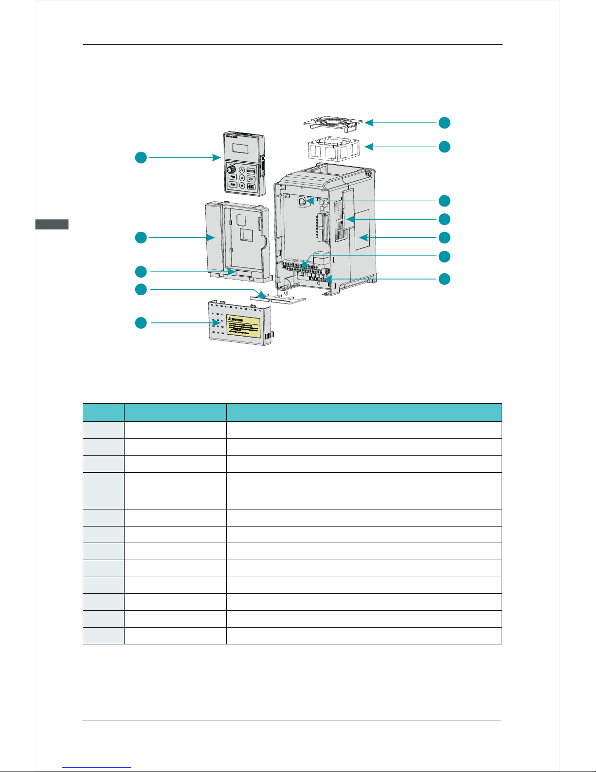
2.7 Structure diagram
2.7.1 The following figure shows the layout of the AC drive ( 7.5KW,for example).
1
2
3
4
5
6
7
8
9
10
11
12
Figure 2-6 Product st ructure diagram
Name
Description
1
No
2
3
4
5
6
7
8
9
10
11
12
Fan-cover
Protection fan.
Refer to 8.1 "Maintenance and hardware diagnostics."
It is used to connect the Keypad.
Optional. with the vents-cover installed, the protection level will
increase and the AC drive internal temperature will increase as
well so please derating use the AC drive.
Refer to 2.4 "Operating principle and Product Overview."
Refer to 3.3 "Electrical Installation."
Refer to 3.3 "Electrical Installation."
Refer to chapter4 "Keypad operating procedures."
Protect the internal components.
Refer to 2.3 "Naming Rules".
Convenient input and output wiring.
Protect the internal components.
Cooling fan
Keypad interface
Vents-cover
Nameplate
Control terminals
Main circuit terminals
Keypad
Cabinet-cover
Lower-cover
Series Label
Apron
Page 23
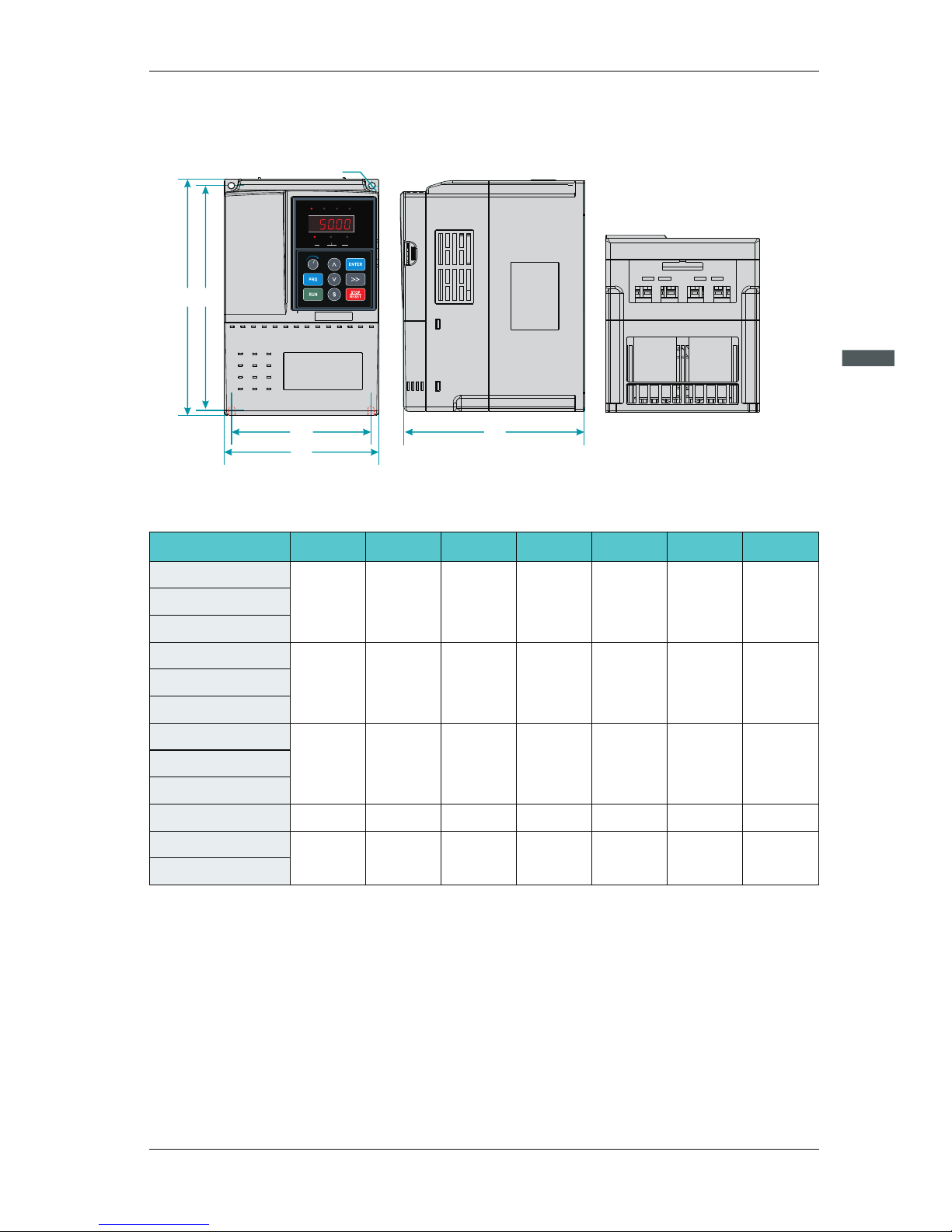
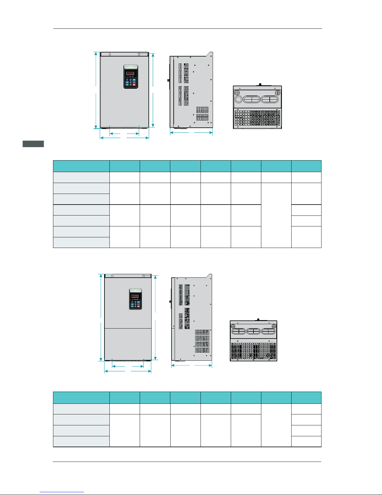
Figure 2-7 Less than 7. 5 KW AC drive installat ion dimensions and in st allation size
D
H
W
W1
H1
Ø
DIGI TAL PAN EL
DIGI TAL PAN EL
Hz
A
V
RPM
%
FWDREV/RUNTUNE/ LOCALREMOT/ TRIP
2
SD200 User Manual
Chapter 2 Product Information
-2 3-
2.7.2.1 SD200 series less than7.5KW (including 7.5KW)
2.7.2 Product Outline, Installation Hole Size
AC drive model
H(mm) W(mm) D(mm)
H1(mm) W1(mm)
D
(mm)
iameter
GW(kg)
SD 200-4 T-0.7G
SD 200-4 T-1.5G
SD 200-4 T-2.2G
SD 200-4 T-4.0G
SD 200-4 T-5.5G
SD 200-4 T-7.5G
19 0 11 0 15 0 17 8 98
Ø5
2. 4
21 0 13 0 16 0 19 8 11 8
Ø5
3. 5
25 0
15 5
17 6 23 6
14 1
Ø5
4. 5
SD 200-2 S-0.7G
SD 200-2 -1.5S G
SD 200-2 -2.2S G
SD 200-2 T-0.7G
SD 200-2 T-1.5G
SD 200-2 T-2.2G
19 0 11 0 15 0 17 8 98
Ø5
2. 4
19 0 11 0 15 0 17 8 98
Ø5
2. 4
Page 24
2
SD200 User Manual
Chapter 2 Product Information
-2 4-
2.7.2.2 SD200 Series 11KW~45KW
D
H
W
W1
H1
DIGITAL PANEL
DIGITAL PANEL
Hz
A
V
RPM
%
FWD/REVRUN/TUNE LOCAL/REMOTTRIP
Figure 2-8 11kw~45k w AC drive installati on dimensions and insta llation size
17 0 16 2 27 0
Ø6
22 0
21 4
31 8
Ø7
25 0 22 0 37 3
5. 1
9. 3
19
28 5
33 2
38 7
27 0 25 2 42 6 2544 0
13 5
14 0
15 0
18 0
SD 200-4 T-11G
SD 200-4 T-15G
SD 200-4 T-18.5G
SD 200-4 T-22G
SD 200-4 T-30G
SD 200-4 T-37G
SD 200-4 T-45G
14
AC drive model
H(mm) W(mm) D(mm)
H1(mm) W1(mm)
D
(mm)
iameter
GW(kg)
D
H
H1
W1
DIGITAL PANEL
DIGITAL PANEL
Hz
A
V
RPM
%
FWD/REVRUN/TUNE LOCAL/REMOTTRIP
W
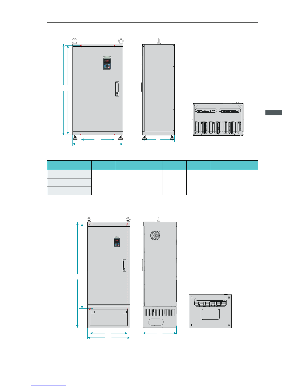
2.7.2.3 SD200 Series 55KW~110KW
Fig 2-9 55~110KW AC dri ve installation dim ensions and installat ion size
30 0 25 8 53 4 20 0
37 0 28 2 62 5 25 0
Ø9
3255 0
65 0
52
55
58
SD 200-4 T-5 G5
SD 200-4 T-75G
SD 200-4 T-90G
SD 200-4 T-110G
AC drive model
H(mm) W(mm) D(mm)
H1(mm) W1(mm)
D
(mm)
iameter
GW(kg)
Page 25
2
SD200 User Manual
Chapter 2 Product Information
-2 5-
SD 200-4 T-132G
88 0 48 5 31 0 86 0 32 0
Ø1 3
99SD 200-4 T-160G
SD 200-4 T-185G
AC drive model
H(mm) W(mm) D(mm)
H1(mm) W1(mm)
D
(mm)
iameter
GW(kg)
2.7.2.4 SD200 Series 132KW~185KW
H
H1
W
W1
DIGITAL PANEL
DIGITAL PANEL
Hz
A
V
RPM
%
FWD/REVRUN/TUNE LOCAL/REMOTTRIP
D
Figure 2-10 132KW~1 85KW AC drive install ation dimensions and in stallation size
2.7.2.5 SD200 Series 200KW~500KW
H
H1
W1
DIGITAL PANEL
DIGITAL PANEL
Hz
A
V
RPM
%
FWD/REVRUN/TUNE LOCAL/REMOTTRIP
W
D
Figure 2-11 200KW~5 00KW AC drive install ation dimensions and in stallation size
Page 26
2
SD200 User Manual
Chapter 2 Product Information
-2 6-
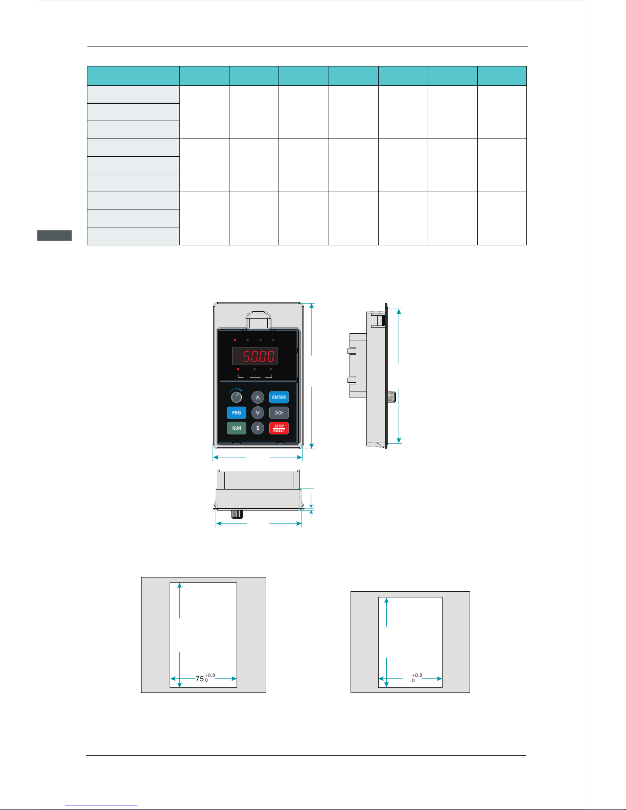
2.7.3 External Keypad Installation Dimensions
Figure 2-12 Keypad In stallation dimens ions
119.00
128.20
79.00
DIG ITAL PA NELDIG ITAL PA NEL
Hz
A
V
RPM
%
FWDREV/RUNTUNE/ LOCALREMOT/ TRIP
74.80
1.50
AC drive model
H(mm) W(mm) D(mm)
H1(mm) W1(mm)
D
(mm)
iameter
GW(kg)
SD 200-4 T-200G
SD 200-4 T-220G
SD 200-4 T-250G
SD 200-4 T-280G
12 50 50 0 40 0 100 0 440
Ø1 3
16 7
SD 200-4 T-315G
SD 200-4 T-350G
SD 200-4 T-400G
SD 200-4 T-450G
SD 200-4 T-500G
13 50 65 0 40 0 110 5 513
Ø1 3
20 6
18 10 85 0 40 5 141 0 513
Ø1 3
41 5
Figure 2-14
Opening dimension d iagram
for keypad without ba se
Figure 2-13
Opening dimension d iagram
for keypad with base
11 9.5
+0. 3
0
10 0
+0. 3
0
70
Page 27
2
SD200 User Manual
Chapter 2 Product Information
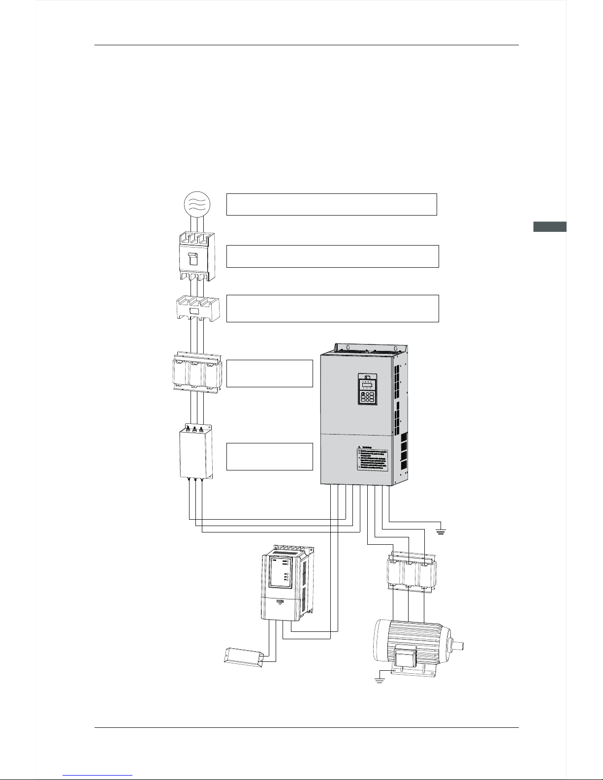
-2 7-
When using SD200 s eries AC drive to control a sy nchronous motor syste m, you have to
install va ri ous electrical components on the side of input and output o f the AC drive to
guarantee the stabili ty and safety of s ys te m.In addition, SD200 series AC drive is
equipped with a variety of optional accessories and expansion card to achieve various
functions. More than 37kw series three-phase 380v system structure as sh ow n in the
figure below (T he figure AC drive terminal refer to 55~110KW):
2.8 Peripheral Electrical Components System Structure
Figure 2-15 Under 37 kw s eries 3-phase 380 V sys tem structure diagr am
T
S
R
P-
P+
P
PB
P+
BR
PE
W
V
U
P
P-
P+
3-phase AC
power supply
Use within the allowable power supply specif icati on
of the AC d rive
Moulded case
circuit breakeror
earth leakage
circuit breakers
Select a proper breaker to resistlarge in-rush current
that flows into the AC drive at power-on
To guarantee safety, use an electromagnetic contactor.
Do not use it to start or stop the AC drive because such
operation reduces the service life of the AC drive
Suppress the high
order harmonic to
improve power factor
Electromagnetic
contactor
AC reactor
Reduce the electromagnetic interference
on the input side.
Input side EMC
filter
Break unit
Braking resistor
Ground
Output reactors
Ground
Motor
AC Driver
Page 28

2.8.1 Peripheral Electrical Components Description
2
SD200 User Manual
Chapter 2 Product Information
-2 8-
Installation
position
Function Description
Accessory
Name
MCCB
Interrupt th e po wer supply when overcurrent occurs
ª
on downstrea m de vices.
Power
receiving side
Contactor
ª
drive frequently by switching the contactor on and off
(less than twice per minute) nor use it to directly start
the AC drive.
Start and stop the AC drive.Do not start and stop the AC
Between MCCB
and the AC drive
input side
AC input
reactor
ª
Eliminate the higher harmonics of the input side effecti-
ª
vely and prevent other devices from being damaged due
to distortion of the voltage waveform;
Eliminate the input current unbalance due to unbalance
ª
between the power phases;
Improve the power factor of the input side;
AC drive
input side
EMC input
filter
ª
nce of the AC drive;
Decrease the conduction interference flowing from the
ª
power end to the AC drive and improve the anti-interfe rence capacity of the AC drive.
Reduce the external conduction and radiation interfere-
AC drive
input side
DC reactor
ª
Improve the efficiency and thermal stability of the AC
ª
drive;
Eliminate the impact of higher harmonics of the AC drive
ª
input side and reduce the external conduction and
radiation interference.
Improve the input power factor;
SD200 series
AC drive of
30G and above
configured
with DC reactor
as standard
AC output
reactor
ª
higher harmonics. When the motor is far from the AC
drive, there is much distributed capacitance in the circuit
and certain harmonics may cause resonance in the
circuit, bringing about the following two impacts:
a.Degrade the motor insulation performance and damage
the motor in the long run.
b.Generate large leakage current and cause frequent AC
drive protection trips.
If the distance between the AC drive and the motor is
ª
greater than 100 m, install an AC output reactor.
The output side of the AC drive generally has much
Between the AC
drive output side
and the motor,
close to the AC
drive
Page 29
2
SD200 User Manual
Chapter 2 Product Information
-2 9-
Note:
1.
Otherwise, it may cause faults to the AC drive or damage to the capacitor and surge
suppressor;
2. Input/output (main circuit) of the AC drive include harmonic components, which may
interfere with the AC drive attachment communications equipment. Therefore, install
an anti-aliasing filter to minimize the interference;
3. Details of peripherals and options refer to Chapter 2 selection of peripheral devices.
Do not install capacitor or surge suppressor on the output side of the AC drive.
2.9 SD200 Optional Parts
Peripheral optional braking unit, each function expansion card and the outer lead operator,
etc..As shown below. Seeing detailed usage instructions for use of the accessory. For the
following options, please note when ordering.
Type
RemarkName
Internal
braking unit
Models
followed
by letter "C”
Function
Models power under 22KW are
installed with the internal braking
unit as standard configuration
External
braking unit
SDBUN
37KW and above need to be
configured with an external
braking unit
For 30KW model power,
the braking unit is optional
Multiple braking ones are
connected in parallel for
the models above 90KW
Multi-function
I/O expansion
card
SDIO1
Increase 3 digital inputs, 2 digital
outputs, two relay outputs, two
analog voltage input T_Motor
It applies to all models
Modbus
communication
card
SDCM01
One RS - 485 communication
card, one CAN communication
card.
Coming soon
Profibus-DP
card
SDDP01
Profibus-DP card,DB9interface
Coming soon
External LCD
panel
SDPG01
External LCD display and keypad,
you supply copy parameters
Coming soon
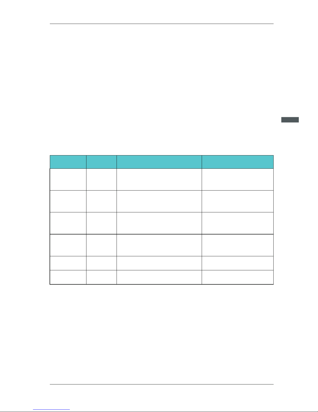
2.9.1 Selection Braking Unit
The section recommend braking assembly is instructional data, user can select different
resistance value and power according to actual situation. (Resistance values can not be
lower than the recommended ones , the power can be higher than recommended ones).
Braking rem inertia, deceleration time, energy of potential energy load. Customs select
the AC drive should comply esistance can be selected according to the power of motor in
actual applied system. They are also related to systwith the actual situation. The bigger of
the system inertia, the shorter of the deceleration time, the more frequent of the braking,
and the braking resistence should select larger power and smaller resistance .
Page 30
2
SD200 User Manual
Chapter 2 Product Information
-3 0-
2.9.1.1 The Selection of Resistance Value
When braking, almost all renewable energy consumption of the motor is on the braking
resistor,According to the formula:
U*U/R=Pb
ª U------ Braking voltage at stable braking system.
(System selections differs in braking voltages, The AC380Vsystem usually selects
DC700V braking voltage.)
ª Pb-----Braking power
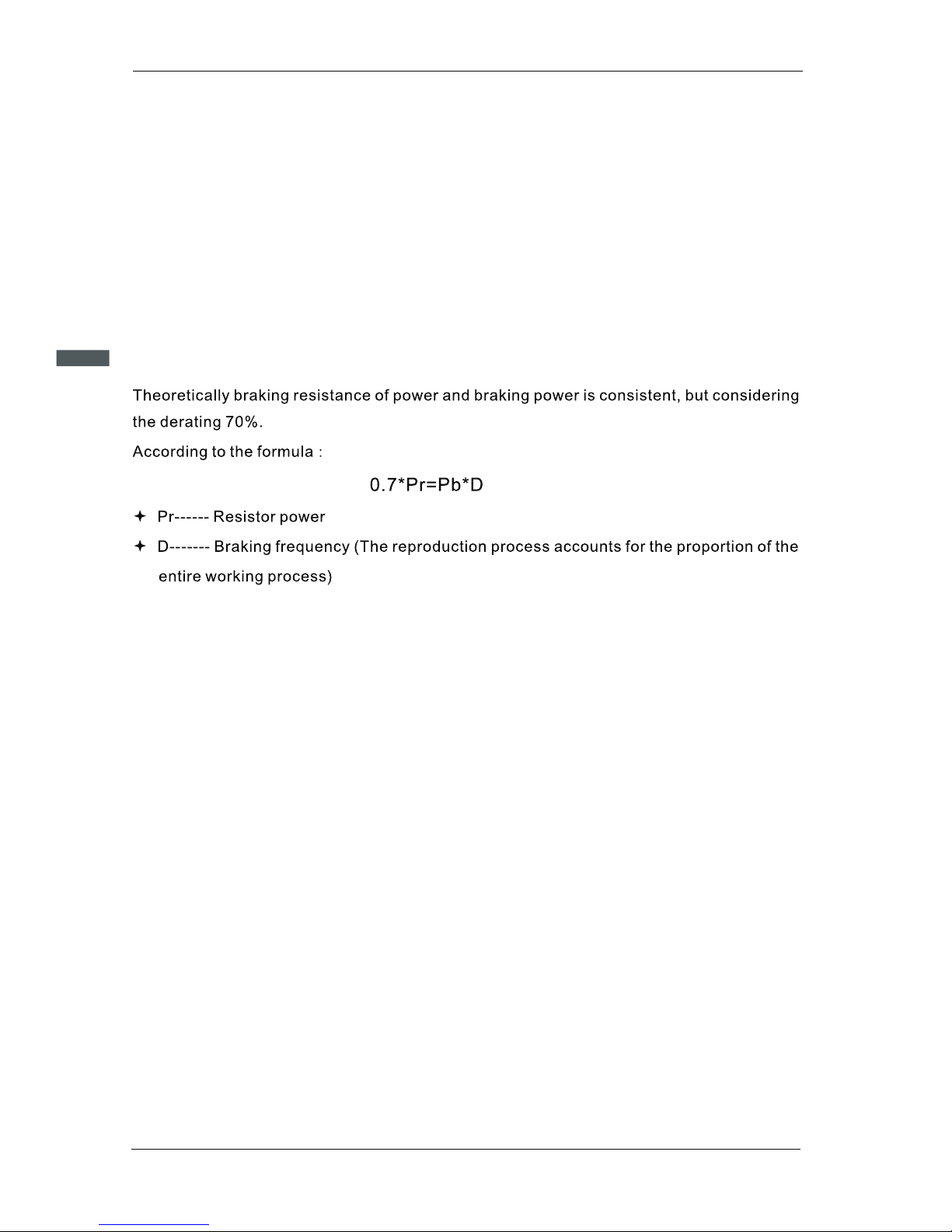
2.9.1.2 The Selection of braking Resistor Power
Elevator---20%~30% Open and draw volume---20%~30%
Centrifuge---50%~60% Accidental braking load---5%
Commonly take 10%
2.9.1.3 Selection of Reference
When the AC drive is driven by the control device requiring rapid braking, the braking unit
needs to release the power of the motor braking feedback to the DC bus. 400V voltage
level 0.4 ~30kw is equipped with built-in braking unit, if you need to rapid stop, please
refer to the appropriate braking to select the unit and braking resistance, AC drive
capacity, if need to stop, it can be directly connected to the braking resistance. Please
choose the appropriate braking unit according to the braking resistance of the AC drive
capacity.
Page 31

2
SD200 User Manual
Chapter 2 Product Information
-3 1-
AC drive
Capacity
(kw)
Braking Unit
Specification
Quantity
Braking Resistor
Resistance
Power
Quantity
≥30 0Ω0. 4
0. 75
1. 5
2. 2
4. 0
5. 5
7. 5
11
15
18 .5
22
30
Built-in as
standard
1
1
1
1
1
1
1
1
1
1
1
1
≥30 0Ω
≥22 0Ω
≥20 0Ω
≥13 0Ω
≥90 Ω
≥65 Ω
≥40 Ω
≥32 Ω
≥25 Ω
≥22 Ω
≥16 Ω
15 0W
15 0W
15 0W
25 0W
30 0W
40 0W
50 0W
80 0W
10 00W
13 00W
15 00W
25 00W
1
1
1
1
1
1
1
1
1
1
1
1
37
45
55
75
90
1
1
1
2
2
≥16 Ω
≥16 Ω
≥8Ω
37 00W
45 00W
55 00W
37 00W
45 00W
1
1
1
EHBU70
11 0
16 0
20 0
13 2
18 5
22 0
2
3
4
3
4
4
55 00W
55 00W
55 00W
37 00W
45 00W
55 00W
≥8Ω
≥8Ω
≥8Ω
≥8Ω
≥8Ω
≥8Ω
≥8Ω
≥8Ω
2
2
2
3
4
3
4
4
SD200 series under 30KW(30KW included) AC drive braking resistor connection as shown
in figure 2-16.
2.10 Connection Methods
2.10.1 Braking Resistor Connection
Figure 2-16 braking r esistor connectio n
Braking
resistor
P+
PB
AC Driver
Page 32

SD200 User Manual
Chapter 2 Product Information
-3 2-
2
SD200 series AC drive and the braking unit connection as shown in figure 2 -17.
2.10.2 Braking Unit Connection
Wh en a s ingle braking unit failin g t o m eet the needs of the braking energ y, two or more
br aking on es ar e requir ed in paralle l connection, as shown in figure 2-18.
2.10.3 Braking ones in Parallel Connection
Figure 2-17 braking u nit connection
+
-
B2
B1
braking
unit
P+
P-
AC Driver
Braking
resistor
Figure 2-18 braking o nes in parallel conne ct ion
+
-
B2
B1
P+
P-
+
-
B2
B1
AC Driver
Braking
resistor
braking
unit
Braking
resistor
braking
unit
Page 33

Chapter 3
Mechanical and Electrical Installation
3.1 Chapter of This Content
This chapter i nt roduce the mechanical and electrical installation of the AC drive.
Danger
Only those who are traine d a nd qualified professi onals can operate the wor k de scribed
ª
in thi s c hapter. Please operate according to the se ction of "pay attentio n to security
matters", failure t o these may cause perso nal injury or damage to e qu ipment.
Power supply of AC dr ive must be disconn ec ted before the inst allation. If the AC d rive
ª
has connected to power, please power off fir st an d the n wai t not le ss th an th e time
marked on the AC drive an d confirm the Charge La mp was already of f, users in such
condition are advised to use the multim eter to measure if the DC bus voltage of the AC
drive is under 36v.
The installation and design of the AC drive must comply with relevant laws and
ª
regulations of th e installation regi on. If the installa tion of the AC drive vi olates the
requirements of local l aw s an d re gulations, We Our company d oes not as su me any legal
responsibility. In addition, if user are not comply with the recommendati on s, the AC
drive may appear some f aults not covered by th e warranty.
-3 3-
Page 34

SD200 User Manual
Chapter 3 Mechanical and Electrical Installation
-3 4-
3
3.2 Mechanical Installation
3.2.1 Installation Environment
In order to ma ke full use of th e perfor mance of the AC drive an d mainta in its functi on for a
lo ng time, it is ver y im portant to instal l the envi ronment . Please install the AC drive in the
fo llowing table of the desc ribed environment .
Conditions
Environment
Installation site Indoor
Ambient
temperature
ª
If the ambien t temperature of the AC drive is above 40℃, dera te
ª
3% for every add it ional 1℃.
It is not recommended to use the AC drive if the ambient
ª
temperatur e is a bove 50℃.
In order to impr ov e the reliability of the device, do not use the
ª
inverter if th e am bient temperature changes frequently.
Please provide co ol ing fan or ai r conditioner to control the
ª
internal ambient temperature below the required one if the AC
drive is used in a c lo se space such as in the control cabinet.
When the temperature is too low, if the AC drive needs to restart
ª
to run after a long stop, it is necessary to provide an extern al
heating device to increase the internal temperature, other wi se
damage to the de vi ces may occur.
-10~+50℃
Humidity
ª
No condensation is allowed, The maximum relative humidity should
ª
be equal to or less than 60% in corrosive air.
Rh≤90%
Storage
temperature
-30~+60℃
Running
Environment
Condition
The installation site of the AC drive should:
keep away from the electromagnetic radia tion source
ª
keep away from contaminative air, such as corrosive gas, oil mi st
ª
and flammable gas;
ensure foreign objects,such as metal pow er,dust,oil,water can not
ª
enter into the AC drive(do not install the AC drive on the flammable
materials such as wood)
keep away from direct sunlight,oil mist,steam and vibration
ª
environment;
;
Altitude
<1000m,If th e se a level is above 100m,please derate 1% for every
addition al 1 00 m.
Vibration
≤5.8m//s²(0 .6 g)
Installation
direction
AC drive shoul d be i nstalled on an upright position to ensure sufficient
cooling effe ct .
Page 35

SD200 User Manual
Chapter 3 Mechanical and Electrical Installation
-3 5-
Note:
1.
ing to enclosure classification.
2. Cooling air must be clean,free from corrosive materials and electrically conductive dust.
SD200 series AC drive should be installed in a clean and ventilated environment accord-
3.2.2 Installation Direction
Th e AC driv e may be installe d on the wall or in a cabinet.
Th e AC driv e must be install ed in an upright position. Check th e instal lation site accord ing
to the requ irements below.Re fer to chapter 3. 1 outlin e diagra m for fra me de tails.
Figure 3-1 Installa tion direction of AC dr ive
OK
A. Vert ical installation
B. Alinic installation
NG
C. Tran sverse installation
NG
Figure3-2 Install ation manner
3.2.3 Installation Manner
Wa ll mo unting(for the AC drive of 380V≤315KW)
1.
charpter;
2. Fix the screws or bolts to the marked locations;
3. Put the AC drive against the wall;
4. Tighten the screws in the wall securely.
Mark the hole location. The location of the holes is shown in the outline diagram in 3.2
3
Page 36

SD200 User Manual
Chapter 3 Mechanical and Electrical Installation
-3 6-
3
3.2.4 Single Installation
3.2.5 Multiple Installation
Figure 3-3 Single ins tallation
Note:
The minimum space of B and C is 100mm.
Figure 3-4 Parallel i nstallation
Warm Air
Cool Air
C
C
A
A
B
B
D
Note:
1.
ience of later maintenance;
2. The minimum space of B, D and C is 100mm.
Before installing the different sizes AC drive, please align their top position for the conven-
B B
A
A
C
C
Warm Air
Cool Air
Page 37

3
SD200 User Manual
Chapter 3 Mechanical and Electrical Installation
-3 7-
3.2.6 Vertical Installation
Figure 3-5 Vertical i nstallation
C
ool
A
ir
Wind Board
Warm
Ai
r
Wind Board
W
a
rm
A
ir
Cool Ai
r
Note:
Windscreen should be installed in vertical installation for avoiding mutual impact and insuffici-
ent cooling.
Page 38

SD200 User Manual
Chapter 3 Mechanical and Electrical Installation
-3 8-
3
3.2.7 Canted Installation
Figure 3-6 Tilt insta llation
W
arm A
i
r
C
o
ol
Ai
r
W
ar
m
A
i
r
Cool A
i
r
W
a
rm
Air
Cool A
i
r
Note:
Ensure the seperation of the wind input and output channels in tilt installation for avoiding
mutual impact..
Page 39

3
SD200 User Manual
Chapter 3 Mechanical and Electrical Installation
-3 9-
3.3 Standard Wiring
3.3.1 Main Circuit Wiring Diagram
Figure 3-7 Main circu it wiring diagram
M
P+ P-
18.5KW
(including)Below
MCCB
R
S
T
3-phase 380V
input power 50/60HZ
PB
W
V
U
PE
R
S
T
braking resistor
R
S
T
22~30KW
P
P+
P-
M
PB
DC reac tor
R
S
T
W
V
U
PE
3-phase 380V
input power 50/60HZ
MCCB
37KW
(including)Above
P
P+
P-
braking unit
DC reac tor
braking r esistor
M
W
V
U
PE
R
S
T
R
S
T
3-phase 380V
input power 50/60HZ
MCCB
Note:
1. DC reactor, braking unit and braking resistor are optional accessories”.
2. P1 and(+) are short circuited in factory, if need to connect with the DC reactor, please
remove the contact tag between P1 and (+).
3.3.2 Main Circuit Terminals Diagram
Figure 3-8 7.5KW belo w main circuit termin al diagram
P+ P- PB R S T U V WP+ P- PB R S T U V W
PEPE
Page 40

SD200 User Manual
Chapter 3 Mechanical and Electrical Installation
-4 0-
3
Figure 3-9 11~18.5k w main circuit termin al diagram
P+ P- PB R S T U V W
PE
P+ P- PB R S T U V W
PE
P+ P- P B R S T U V W PEP+ P- P B R S T U V W PE
DIGITAL PANEL
FWD/REVRUN/TUNE LOCAL/REMOTTRIP
Hz A V
RPM
%
Figure 3-10 22kw main c ircuit terminal dia gram
PE
P P+ P- P B R S T U V W
PE
P P+ P- P B R S T U V W
DIGITAL PANEL
FWD/REVRUN/TUNE LOCAL/REMOTTRIP
Hz A V
RPM
%
PE
P P+ P- PB R S T U V W
PE
P P+ P- PB R S T U V W
Figure 3-11 30kw main c ircuit terminal dia gram
R S T PB P P+ P- U V W R S T PB P P+ P- U V W
R S T PB P P+ P - U V W
PE
R S T PB P P+ P - U V W
PE
DIGITAL PANEL
FWD/REVRUN/TUNE LOCAL/REMOTTRIP
Hz A V
RPM
%
PEPE
Figure 3-12 37~45kw m ain circuit termina l diagram
R S T P P+ P- U V W
R S T U V W P P+ P-
POWE R(电源)
POWE R(电源)
MOTO R(电机)
MOTO R(电机)
PE
PE
DIGITAL PANEL
FWD/REVRUN/TUNE LOCAL/REMOTTRIP
Hz A V
RPM
%
R S T P P+ P- U V W
R S T U V W P P+ P-
PO W ER (电源)
PO W ER (电源)
MO T OR (电机)MO T OR (电机)
PEPE
Page 41

3
SD200 User Manual
Chapter 3 Mechanical and Electrical Installation
-4 1-
Figure 3-14 380V 132~ 185kw main circuit te rminal diagram
R
R
S
S
T
T
P
P
P-
P-
U
U
V
V
W
W
PE
PE
P+
P+
R
R
S
S
T
T
P
P
P-
P-
U
U
V
V
W
W
PE
PE
P+
P+
DIGITAL PANEL
FWD/REVRUN/TUNE LOCAL/REMOTTRIP
Hz A V
RPM
%
Figure 3-15 380V 200~ 500kw main circuit te rminal diagram
P+
P+
R
R
S
S
T
T
P
P
U
U
V
V
W
W
PEPE
P-
P-
P+
P+
R
R
S
S
T
T
P
P
UUV
V
W
W
PE
PE
P-
P-
DIGITAL PANEL
FWD/REVRUN/TUNE LOCAL/REMOTTRIP
Hz A V
RPM
%
Figure 3-13 55~110k w main circuit termin al diagram
P P+ P- R S T U V W
P P+ P- R S T U V W
POW ER(电 源)
POW ER(电 源)
MOT OR(电 机)MOT OR(电 机)
PEPE
DIGITAL PANEL
FWD/REVRUN/TUNE LOCAL/REMOTTRIP
Hz A V
RPM
%
P P+ P- R S T U V W
P P+ P- R S T U V W
POWE R(电源)
POWE R(电源)
MOTO R(电机)
MOTO R(电机)
PE
PE
Page 42

SD200 User Manual
Chapter 3 Mechanical and Electrical Installation
-4 2-
3
Terminal
Terminal Name
18.5KW
(including)
below
Function Description
22~33KW
R、S T、
Power input of the main circuit
3-phase AC input terminals
which are generally connected with the power supply.
Braking resistor
terminal
P
Without the
terminal
P+
P、P1 and (+) are connected
with the terminals of DC
reactor.
(+) and (-) are connected
with the terminals of braking
unit.
PB and (+) are connected
with the terminals of braking
resistor.
P P
P
DC reactor
terminal
P-
/
/
PB
400V:Grounding resistance is less than 10Ω
PE
Protective grounding terminals, every machine is provided 2 PE terminals as the
standard configuration.These
terminals should be grounded
with proper techniques.
37KW
(including)
above
DC reactor
terminal
DC reactor
terminal
braking unit
terminal
Braking unit
terminal
Without the
terminal
AC drive output
U、V W、
Three-phase AC output terminals, general connected to
the motor.
DC reactor
terminal braking resistor
terminal
Braking resistor
terminal
Braking resistor
terminal
Note:
1. Do not use an asymmetrically constructed motor cable. If there is a sysmmetically cons-
tructed grounding conductor in the motor cable in addition to the conductive shield,con-
nect the grounding conductor to the grounding terminal at the AC drive and motor ends;
2. Braking resistor, braking unit and DC reactor are optional parts;
3. Route the motor cable,input power cable and control cables seperately;
4. If the terminal description is"/",the machine does not provide the terminal as the external
terminal.
Page 43

3
SD200 User Manual
Chapter 3 Mechanical and Electrical Installation
-4 3-
3.3.3 Main Circuit Terminal Wiring Process
1. Fasten the grounding conductor of the input power cable with the grounding terminal of
the AC drive(PE)by 360 degree grounding technique. Connect the phase conductors to
R, S, and T terminals and fasten;
2. Strip the motor cable and connect the shield to the grounding terminal of the AC drive by
360 degree grounding technique. Connect the phase conductors to U, V and W
terminals and fasten;
3. Connect the optional brake resistor with a shielded cable to the designated position by
the same procedures in the previous step;
4. Secure the cables outside the AC drive mechanically.
Figure 3-15 Screw ins tallation diagram
NG Y
Screws are not fastened Screws are fastened
Figure 3-16 360-deg ree grounding techn iq ue diagram
PE
OK
Enclosure
Enclosure
Correct grounding method
PE
PE
NG
Enclosure
Enclosure
Wrong grounding method
Page 44

3.3.4 Control Circuit Wiring Diagram
SD200 User Manual
Chapter 3 Mechanical and Electrical Installation
-4 4-
3
Figure 3-17 Wiring di agram of Control Circ uit
3-phase380V/480V
Input power 50/60Hz
braking resistor
Digital input 1
Digital input 2
Digital input 3
Digital input 4
Digital input 5
High-speed pulse input
Keypad interface
Open collector output 1
(High-speed pulse output)
Open collector output2
Relay output1
Relay output2
Expansion card interface
MCCB
AI 2
AI 1
+1 0V
DC:0~10V/0~20mA
DC:-10V~10V
1kΩ 5kΩ~
R
S
T
SD200
1
2
3
GND
CO M
DI 5
HD I1
DI 4
DI 3
DI 2
DI 1
OP EN
DI SP1
J7
AO 2
GN D
HD O1
CM E
CM E
T1 C
T1 B
T1 A
DO 1
J4
I
V
Analog output AO 1,AO2
0V-10V/0mA-20mA
J9
I
V
T2 C
T2 A
AO 1
J3
I
V
A
B
485 communication interface
+2 4V
485
OFF
ON
DC:-10V~10V
AI 3
A
B
T
S
R
S
T
U
V
W
PB
P-
P+
M
Main circuit
Control circuit
PE (connec t ca binet )
An alog inpu t
re ference v oltage
An alog inpu t 1
An alog inpu t 2
An alog inpu t 3
Note:
This diagram is only suitable for the AC drive’s power rate below SD200-4T-18.5,for other
power rate refer to this chapter 3.3"Main Circuit Terminal Wiring".
Page 45

3
SD200 User Manual
Chapter 3 Mechanical and Electrical Installation
-4 5-
DIGITAL PANEL
FWD/REVRUN/TUNE LOCAL/REMOT TRIP
Hz A V
RPM
%
A
+10V
AI2
AO1 AO2 HDI 1 DI2 DI4 OPEN +24V COM
T1A
B
AI1
GND
AI3
GND D I1
DI3 DI5
COM CME HOD1 DO1
T1B T1C
T2A
T2C
3.3.5 Control Panel Terminals
Figure 3-18 Control t erminal diagram
Control Panel Terminal Function Instructions
Specification
Type
Analog
input
Terminal
+10V
Terminal name
Analog input
reference
voltage
10.5V(+3%)
Maximum output current 25mA/ the potentiometer
resistance range is more than 4KΩ.
Internal isolated with COMGND
Analog ground
0~20mA:Input resistance 500Ω, max input current is 25mA
Input range: 0–10VDC/0–20 mA, switched by jumper J9 on
the control board and factory defaulted as voltage input.
0~10V:Input resistance 100KΩ, max input voltage 12.5V
AI1
Analog Input 1
-10V~10V:Input resistance 25KΩ
Max. input voltage range:-12.5V~+12.5V
AI2
Analog Input 2
-10V~10V: Input resistance 25KΩ
Max input voltage range: -12.5V~+12.5V
AI3
Analog Input 3
0~20mA:Input resistance 200Ω~500Ω
Input range: 0–10 VDC/4–20 mA, switched by jumper J3 on
the control board and factory defaulted as voltage input.
0~10V:Input resistance >10KΩ
AO1
Analog output 1
Digital
output
0~20mA:Input resistance 200Ω~500Ω
Input range: 0–10 VDC/4–20 mA, switched by jumper J4 on
the control board and factory defaulted as voltage input.
0~10V:Input resistance >10KΩ
AO2
Analog output 2
Internal isolated with COMGND
Analog ground
Switch the high and low electric level during digital input, it
was connected with + 24 V short circuit in factory which
means it’s effective when the digital input is with low level.
24V±10%,Internal isolated with GND
+24V +24V
OPEN
Digital input
terminal common
Page 46

SD200 User Manual
Chapter 3 Mechanical and Electrical Installation
-4 6-
3
Cont rol Panel Terminal Function Instructions(continued)
Specification
Type
Digital
input
Terminal
DI1~DI5
Terminal name
Digital input 1-5
Input specification:24VDC,5mA
Internal isolated with GNDCOM
+24V
Frequency range:0~200Hz
Voltage range:10V~30V
HDI1
High-speed
pulse input /
digital input 6
Voltage range:10~30V
Digital input: equal with DI1~DI5
Voltage Pulse input Maximum frequency 50KHz:
DO1
Open collector
output
Current range:0~50mA
Voltage range:0~24V
Digital
output
HDO1
High-speed
pulse output
Pulse output::0~50KHz
CME
DO1/HDO1
Digital output
public ground
CME and COM is internal isolated, but the factory has an
external short circuit (DOI default is + 24V drive). when DO1
driven with an external power supply, it must be disconne cted the external shorting of CME and COM.
0~20mA: Input impedance: 500Ω Max input current: 25mA ,
T1A、
T1B、
T1C
Relay 1 output
Contact capacity:250VAC/5A,30VDC/5A
T1A-T1B:NC T1A-T1C:NO
Relay
output
T2A、
T2C
Relay 2 output
Contact capacity:250VAC/3A,30VDC/3A
T2A-T2C:NO
A
485 differential
signal +
Speed rate:1200/2400/4800/9600/19200/38400
Rs485
commun
-ication
485 differential
signal -
Use twisted pair or shielded cable, the longest distance:300m
B
Internal isolated with COMGND
Analog ground
Switching Dial Code Switch Function Description
Factory setting
Name
Jumpers
Figure
Function
485
ON
OFF
AI1
I
V
0~10V
OFF
Rs485 communication terminating resistor selection
ON: 120Ω termination resistor connection is valid
OFF: Without termination resistor connection
I is the current input(0~20mA)
V is voltage input(0~10V)
AO1
I
V
0~10V
I is current output(0~20mA)
V is voltage output(0~10V)
Page 47

Switching Dial Code Switch Function Description(continued)
Factory setting
Name
Jumpers
Figure
Function
J14,J15
Choose whether connect PE with GND/COM.
Occcasions with interference, Connect PE
with GND/COM can improve the ablility to
resist the interference.
AO2
I
V
0~10V
I is current output(0~20mA)
V is voltage output(0~10V)
3
SD200 User Manual
Chapter 3 Mechanical and Electrical Installation
-4 7-
T/A,S/B
TAS
B
T S
A
B
Speed tracking / closed-loop encoder input
function selection
T and S group: speed tacking option
A and B group: closed-loop encoder impulse
selection
Note:
only allow appear the following
combination:T and S, or A and B
COM
GND
J15
J14
When no connection(Jumper is
on the right side of the control
board when you face to the
control board)
Note:
For the selection of the jumper of T/A,S/B, when you choose the speed tracking start func-
tion, please set the combination of T and S.
3.3.6 Input/output signal connection diagram
3.3.6.1 AI Analog input terminal
We ak analog volta ge signals are easy to suf fer e xternal inte rferenc e, and t herefore the
sh ielded c able mus t be us ed and the cabl e length must b e less than 20 m, as shown in
fo llowing figure3-19.In applic ations where the analog signal suffers severe inter ference,
in stall fi lter cap acitor or ferrit e magnet ic core at the analog signal so urce, as shown in th e
fo llowing figure 3-20.
Fig3-19 Analog inpu t and output terminal w iring diagram
+10V
AI1
GND
PE
<20米
AC Driver
Figure 3-20 Analog in put terminal proces s wiring diagram
AI1
GND
In the same direction or in the same
direction through about 2 to 3 turns
Ferrite bead
0.022UF
50V
C
AC Driver
Page 48

3.3.6.2 DI Digital Input Terminals
Ge nerally, select shielded cable no longer th an 20 m. When active driving is adopted,nece ssary fi ltering measures shall be taken to prevent the interfere nce to th e power supply.
It is recommend ed to use the contact control mode.
SD200 User Manual
Chapter 3 Mechanical and Electrical Installation
-4 8-
3
+24V
+24V
OPEN
+VCC
Singnal
DI1
DI5
COM
2.4K
0V
2.4K
NPN
3.3Ω
External
controller
AC drive control board
Figure 3-21 Sink wiri ng
Th is is t he most commonly used wiring mode. To apply external power supply, remove
ju mpers between +24 V and O PEN and connect the 24V pos itive pole of e xternal power
su pply to OPEN and connec t the ext ernal p ower 0V to the c orresponding DI terminal via
co ntrol th e contact control.
Note
In this In such wiring mo de, the DI terminals of d ifferent AC drives ca nn ot be connected in
ª
parallel. Otherwi se, DI mal-function m ay result. If paralle l co nnection (differe nt AC drives)
is required, connec t a diode in series at the DI a nd the diode needs to sat is fy the
requirement: IF>1 0mA, UF <1 V.As shown in Fi gure 3-22.
Figure 3-22 DI termin als connected in
parallel in SINK mo de
+24V
OPEN
+VCC
信号
DI1
DI1
COM
2.4K
0V
2.4K
NPN
3.3Ω
+24V
+24V
OPEN
COM
AC drive 1
control board
AC drive 2
control board
External
controller
+VCC
+24V
+24V
OPEN
2.4K
2.4K
0V
DI5
3.3Ω
PNP
信号
DI1
COM
AC drive
control board
External
controller
Figure 3-23 Source Wi ring
Page 49

In such wiring mode, remove the j umper between +24 V and O P. Con nect + 24 V to the
co mmon port of ext ernal control ler an d meanwhile connect OP to COM. If exte rnal power
su pply is ap plied, remove the jumper between +24V and OPEN,.and conn ect t he OP EN
wi th the 0V of the ex ternal powe r su pply, the external power +24 V ne ed to be connecte d
to the c orrespond ing DI terminal on its way pa ssing the co ntact c ontrol of ex ternal
co ntroller.
3
SD200 User Manual
Chapter 3 Mechanical and Electrical Installation
-4 9-
3.3.6.3 DO Digital Output Terminal
Wh en the digital o utput terminal need s to drive the relay, an absorptio n di ode sh all be
in stalled betwe en two sides of the relay coil. O therwise, it m ay caus e damag e to the 24
VD C power supply. The dr iving ca pacity is not mor e than 50 mA.
Figure 3-24 DO Termin al Wiring diagram
COM
CME
DO1
+24V
electric relay
diode
AC Driver
Note
Do not reverse the pola rity of the absorptio n diode during instal la tion. Otherwise, th e 24V
ª
DC power supply will be d amaged immediatel y on ce there is digital out put.
When the product leav ing factory, digita l output CME and COM are ex te rnal short connect
ª
(Do1 is the default +24 V drive). When the DO dri ven by external power , re move the exter-
nal connection betw een CME and COM short con nection.
3.4 Layout Protection
3.4.1 Protect the AC drive and input power cable in short-circuit situations
Pr otect th e AC driv e and inp ut po wer cabl e in shor t circui t situations and against therma l
ov erload. Arrange the protec tion acc ording to the fol lowing guidelines .
Figure 3-25 Fuse conf iguration diagram
M
3~
Input cable
Fuse
AC drive
DIGITAL PANELDIGITAL PANEL
Hz
A
V
RPM
%
FWD/REVRUN/TUNE LOCAL/REMOTTRIP
Page 50

SD200 User Manual
Chapter 3 Mechanical and Electrical Installation
-5 0-
3
Note:
Select the fuse as the manual indicated.The fuse will protect the input power cable from da-
mage in short-circuit situations. It will protect the surrounding devices when the internal of
the AC drive is short circuited.
3.4.2 Protecting the motor and motor cable in short-circuit situations.
Th e AC drive prote cts th e motor an d moto r cabl e in a shor t-cir cuit situation when the moto r cable is dimen sione d according to th e rated cu rrent of the AC drive. No addit ional prot ection devices are ne eded.
Note
If the AC drive is connected to multipl e mo tors, a seperate thermal over load switch or a
ª
circuit b reaker must be used for protecting each c able and motor. These devic es may
require a seperate fu se to cut off the short-c ircuit current.
Ac cording to reg ulations, the motor m ust be protected against thermal overload an d the
cu rrent must be switched o ff when overload is dete cted. The A C d rive inclu des a motor
th ermal protect ion function that prote cts the motor and closes the output to switch off the
cu rrent wh en ne cessary.
3.4.3 Protecting the motor against thermal overload
It is ne cessary to set power frequency and variable fre quency conv ersion circ uits for the
as surance of c ontinious norma l work of the A C driv e if faults occur in so me sig nificant
si tuations.In some spe cial situa tions, for example, i f it is only us ed in soft start, the AC
dr ive c an be conversed into po wer f requenc y run ning after st arting and some
co rresponding bypass should be added.
3.4.4 Implementing a bypass connection
Note
Never conn ect the supply powe r to th e AC dr ive output termina ls U,V ,W .Power l in e
ª
voltage applied to th e output can result in pe rmanent damage to the A C dr ive.
If frequent shifting i s re qu ired, employ mechanically connected switches or contactors to
ensure th at the motor terminals are not connected to the AC power li ne and inverter output
terminals sim ul taneously.
Page 51

Chapter 4
Operation, Display and Application Examples
4.1 Chapter of This Content
This chapter contains following operation:
Buttons, indicating lights and the screen as well as the methods to inspect, modify and set
function codes by keypad.
-5 1-
Page 52

Th e keypad is us ed to co ntrol SD200 series AC drive, read the state data and adju st pa ram eters.
DIGITAL PANELDIGITAL PANEL
Hz
A
V
RPM
%
FWD/REVRUN/TUNE LOCAL/REMOT TRIP
1
2
4
5
3
Figure 4-1 Keypad dia gram
4
SD200 User Manual
Chapter 4 Operation, Display and Application Examples
4.2 Introduction of the keypad
Name
No.
Status
indicator
Instructions
LED off means that the AC drive is in the stopping state;
LED blinking means the AC drive is in the parameter
autotuning state;
LED on means the AC drive is in the running state.
RUN/TUNE
OFF means the AC drive is in the forward rotation state
ON means the AC drive is in the reverse rotation state.
FWD/REV
LOCAL/
REMOT
Operation pa ne l control
Terminal con tr ol
Communicat io n control
○ FF LOCAL/REMOT:O
● LOCAL/REMOT:PN
○ LOCAL/REMOT:Fla sh
TRIP
LED for faults
LED on when the AC drive is in the fault state;
LED off in normal state
LED blinking means the AC drive is in the pre-alarm state.
1
-5 2-
It is necessary to use M3 scre w or inst allation bracket t o fix the ex ternal keypad. The
in stallation bracket f or AC drive o f 7.5KW is op tional bu t it is stand ard for the A C drive of
be low 11KW .
Note:
Page 53

SD200 User Manual
Chapter 4 Operation, Display and Application Examples
-5 3-
Name
No.
Unit
indicator
Instructions
2
It represents the current display of the Keypad
Hz
A
V
RPM
%
Hz
A
V
RPM
%
Hz
A
V
RPM
%
Hz
A
V
RPM
%
Hz
A
V
RPM
%
Hz
A
V
RPM
%
Frequency unit
Voltage unit
Speed unit
Percentage
Current unit
Code
Display
Zone
3
5-figure LED display displays various monitoring data and alarm code
such as set frequency and output frequency.
Digital
potent-
iometer
4
When the frequency source A or B is set to 1, the setting of the frequency source is determined by the analog potentiometer input voltage .
The maximum output voltage corresponding to the maximum frequency,
minimum voltage corresponding to 0 Hz
Display
letter
Correspo-
nding letter
Display
letter
Display
letter
0
3
6
9
C
F
L
o
S
v
1
4
7
A
d
H
N
P
t
.
2
5
8
b
E
I
n
r
U
-
Correspo-
nding letter
Correspo-
nding letter
4
Program key
Entry key
Up key
Down key
Right-Shift
key
Enter or escape from the first level menu and
remove the parameter quickly
Enter the menu step-by-step confirm parameters
Keypad
button
zone
5
Increase data or function code progressively
Decrease data or function code progressively
Move right to select the displaying parameter
circularly in stopping and running mode. Select
the parameter modifying digit during the parameter modification
Page 54

4
SD200 User Manual
Chapter 4 Operation, Display and Application Examples
-5 4-
Name
No.
Instructions
Stop/Reset
Run key
S Key
This key is used to stop in running state; This key
is used to reset all control modes in the fault
alarm state..
The key is used to operate on the AC drive in key
operation mode
Keypad
button
zone
5
F07.01=0 without function
F07.01=1 jog running
F07.01=2 shift key to change the display state
F07.01=3 switch between forward and reverse
F07.01=4 clear UP/DOWN setting
F07.01=5 coast to stop
SD 200 se ries K eypad display statu ssis d ivided into stopping stat e para meter, running
st ate para meter, function co de parameter editing state an d fault alarm state an d so on.
4.3 Display of Keypad
When the AC drive is in the stopping st ate, the keypad will display stopping parameters. In
the stopping state,various kinds of parameters can b e displayed. Select the parameters
to b e displayed or not by F07.04.See the instructions of F07.04 for the detailed definition
of each bi t.
In the stopping state, ther e are 14 stopping pa ra me te rs can be selected to be displayed or
not. They are: set frequency, bus voltage, input terminals state, output terminals state,
PID given value, PID feedback value, torque set value,AI1,AI2,AI3,HDI,PLC and the
current stage of multi-step speeds, pulse counting value, length value.F07.04can select
the parameter to b e displayed or not by bit and press > > button can s hift the parameters
from left to right, press butoon "S" (F 07 .01 = 2) can shift th e parameters from right to le ft .
4.3.1 Displayed state of stopping parameter
After the AC drive receives valid running commands, the AC dr iv e will enter into the
running state and the keypad will display the running parameters , the "RUN" LED on the
keypad i s on, while the "FWD/REV" is determined by t he current running direction which
is shown as figure 4-2.
In the running sta te , there are 24 parameters can selected to b e displayed or not. They
are: running frequency, set frequency, bus voltage, ou tp ut vo lt ag e, ou tp ut torque, PID
given va lu e, P ID feedback value, input terminals state, output te rminals state, torque set
value, length value, PLC and the current stage of multi-step spe ed s, pulse counting
value,AI1,AI2,AI3,HDI,percentage of motor overload, percentage of AC drive overload,
ramp given value, Linear s pe ed , AC input current.F07.02 and F07.03 c an selec t the
parameter to be dis pl ayed or not by bit and press > > bu tt on can shift the parameters from
left to ri ght, press "S" (F7.01 = 2) can shift the parameters fr om right to left.
4.3.2 Displayed state of running parameters
Page 55

SD200 User Manual
Chapter 4 Operation, Display and Application Examples
-5 5-
4
If the AC drive detects the fault signal, it will en te r into the fault pre-alarm displaying st at e.
The keypad will display the fault code by flicking. The "TRIP key" LED on the keypad is on,
and the fa ult reset can be operated by the "STOP/RST key" on the keypad, control terminals or communication commands.
4.3.3 Displayed state of fault
In the state of stopping, running or fault, press "PRG" to enter into editing state(if there is a
password, see F07.00).The editing state is displayed on two classes of menu, and the order
is: function code group/function code number > function code parameter, press "ENTER"
into the displayed state of function parameter. On this state, you can press "ENTER" to save
the parameters or press "PRG " to retreat.
4.3.4 Function Code Editor Displays Status
4.4 Keypad Operation
Op erate the AC d rive via operat ions pan el. See the detailed str ucture d escript ion of
fu nction code in th e brief diagram of function co des.
4.4.1 How to modify the function codes of the inverter
Th e AC driv e has thr ee-leve l menus, they are:
1. Group number of functio n code(f irst-leve l menu)
2.Tab of function code(second-leve l menu)
3.Set val ue of functio n code(t hird-leve l menu)
Op eration procedu re on the oper ation pa nel:
PRG
50.00 F00
F00.03 F00.04
50.00
ENT ER
ENT ER
return
PRG
return
PRG
ENT ER
(modify storage)
return
PRG
Display parameter
interface
level 1 menu
level 2 menu
level 3 menu
Press modify parameters
Note:
Press both the "PRG" and the "ENTER" key to return to level2 menu from the level3 menu.
The difference is: pressing "ENTER" will save the set parameters into the control panel,
and then return to the level2 menu with shifting to the next function code automatically;
while pressing "PRG" will directly return to the level 2 menu without saving the parameters,
and keep staying at the current function code.
Page 56

Example: Set function code F0C.02 from 10.00Hz to 15Hhz.
4
SD200 User Manual
Chapter 4 Operation, Display and Application Examples
-5 6-
In Level 3 menu, if the parameter has no blinking digit, it means tha t the parameter cannot
be modified. This may be because:
a. Suc h a function code is only readable, such as, AC drive mod el , actually detected
parameter an d running record parameter;
b. Suc h a function code cannot be modified in the running state and can only be changed
at sto p.
Figure 4-3 Modifyin g parameters diagra m
F0C.00
PRG
ENT ER
50.00
F00
F0C
F0C.02
10.00
PRG
F0C F0C.03
15.00
10.00
ENT ER
ENT ER
PRG
SD200 series AC drive provide password protection function to users. Set F07.00 to gain
the password and the password protection becomes valid instantly after quitting from the
fu nctio n code editing state . Pres s "PRG " again t o the f uncti on code e ditin g
state,“0.0.0.0.0”will be displayed. Unless using the correct password, the operators cannot
enter it.
Set F07.00 to 0 to cancel password protection function.
The password protection becomes effective instantly after retreating form the function code
editing state. Press "PRG" again to the function code editing state, “0.0.0.0.0”will be
displayed. Unless using the correct password, the operators cannot enter it.
4.4.2 Password Setting
F07.00
PRG
ENT ER
50.00
F00
F07
0.0.0.0.0
PRG
F07 F07.01
ENT ER
ENT ER
PRG
X.X.X.X.X
Figure 4-4 Password s etting diagram
SD200 series AC drive provide groupA02 as the sate inspection group. Users can enter into
A02 directly to watch the state. Operations procedure as follows:
4.4.3 How to watch the AC drive state through function codes
A02.00
PRG
ENT ER
50.00
F00
A02
PRG
A02
A02.06
ENT ER
ENT ER
PRG
A02.05
1400
Figure 4-5 Motor spee d diagram
Page 57

Chapter 5
Function Parameter Table
5.1 Chapter of This Content
This chapter lists and describes the function parameters.
-5 7-
Page 58

SD200 User Manual
Chapter 5 Function Parameter Table
-5 8-
5
5.2 Function Parameter Table
The function paramete rs of SD 200 series AC drive have been divided into 19 groups (F00-
F0F and A00-A02) acco rding to the fu nc tion. Each functi on group contai ns certain
func ti on codes applying3-level me nus. For example, "F08.08" mean s the eighth function
code in the F8 group function, F0F group i s factory Reserved, and users are forb id den to
acce ss these parameters.
For the convenience of function codes set ti ng, the function group number corresponds to
the fir st level menu, the function co de corresponds to the level 2 men u a nd the function
code corresponds to the level 3 men u.
1. Be low is the instructi on of the function lists:
The first line"Function code":codes of function parameter group and parameters;
The second li ne"Name":full name of function pa rameters;
The third line"Setting range":effective setting value of the funct io n parameters;
The fourth li ne"Default va lue":the or iginal fact ory values of the fun ction parameter;
The fifth line"Modify":t he modifying character of function codes(the parameters ca n
be modified or not and the modifying condi ti ons), below is the instruction:
“○”:mea ns the set value of the paramet er can be modified on stop an d running st ate;
“◎”:mea ns the set value of the paramet er can not be modifi ed on the running stat e;
“● ” :means the v alue of the parameter is the real detection value wh ic h can not be
modi fi ed.
2. "Paramete r radix " is decim al(DEC), if the p arameter is expressed by hex, then the
para meter is separated from each other when editing. The setting range of the certain bits
are0 -F(hex).
3."T he de fault value" means the function parameter will restore to the def au lt valu e
duri ng default parameters resto ring. But the detected para me ter or recorded value won 't
be restored.
4. For a better parameter protection, the AC drive provides password protectio n to the
para meters. A ft er sett in g the password(s et F07.00 to any non-zero number),the system
will come into the state of password verificati on firstly after the user press "PR G" to come
into the function code editing state .And then “0 .0 .0.0.0”will be displayed. Unless the user
inpu t right password, they cannot enter into the system. For the factory setting parameter
zone , it needs correct factory password(remind that the u se rs cannot modify the factory
para meters by themselves, othe rwise, if the parameter setting is incorr ect, dama ge to the
AC drive may occ ur ).If the passw or d protection is un locked, the user can modify the
pass word freely and the AC drive will work as the last s etting one. When F07.0 0 is set to
0,th e pass word can be cancele d. If F07. 00 is no t 0 during pow er ing on, then the
para meter is protected by the password. When modify the parameters by seria l
comm un ication the function of the pa ss word follow s the abov e rules, too.
Page 59

SD200 User Manual
Chapter 5 Function Parameter Table
-5 9-
0:V/F control
1: Vector control 0 mode
F00.00
1
Group F00 Basic Function Group
◎
Name
Setup range
Function
code
Default
Value
Modifi-
cation
Motor 1 control mode
0: Keypad run command channel(LED is OFF)
1: Terminal command channel / Keypad STOP
disabled(LED is ON)
2: Terminal command channel / Keypad STOP
enable(LED is ON)
3:Terminal command channel / Keypad
STOP disabled(LED is flashes)
4:Terminal command channel / Keypad
STOP enabled(LED is flashes)
F00.01
0
Run command
channel
○
0: MODBUS Communication channel
1: CAN Communication channel
Note:
1 means to extension, need to insert the card
F00.02
Communication run
command channel
selection
0
○
F00.04~600.00HzF00.03 50.00Hz
◎
Max output frequency
F00.05~F00.03(Maximum frequency)
F00.04 50.00Hz
◎
Upper limit frequency
0.00Hz~F00.04(Operating frequency upper
limit)
F00.05 0.00Hz
◎
Lower limit frequency
0: Keypad digital setting
1: Keypad potentiometer setting
2:Analog AI1 setting
3:Analog AI2 setting
4:Analog A 3 setting
5: High-speed pulse HDI1 setting
6:Simple PLC program setting
7: Multi-speed running setting
8: PID control setting
9: MODBUS Communication setting
10: CAN Communication setting
Note: 10 means to extension function, need to
insert the card
I
F00.06
0
A frequency
command
○
0: Keypad digital setting
1: Keypad potentiometer setting
2: Analog AI1 setting
3:Analog AI2 setting
4:Analog A 3 setting
5: High-speed pulse HDI1 setting
6: Simple PLC program setting
7: Multi-speed running setting
8: PID control setting
9: MODBUS Communication setting
10: CAN Communication setting
Note:10 means to extension function, need
to insert the card
I
F00.07
3
B frequency
command selection
○
0:Maximum output frequency
1:A frequency command
F00.08
0
B frequency
command reference
5
○
Page 60

SD200 User Manual
Chapter 5 Function Parameter Table
-6 0-
5
Name
Setup range
Function
code
Default
Value
Modifi-
cation
0.0~100.0%
F00.09
100.0%
B frequency maximum
output frequency
○
0: A
1:B
2:(A+B)
3: (A-B)
4: MAX(A,B)
5: MIN(A,B)
F00.10 0
Combination of the
setting codes
○
0.00 Hz~F00.03(Max. frequency)
F00.11 50.00Hz
Keypad setting
frequency
○
0.0~6000.0sF00.12
Depend
on
model
Acc-time 1
○
0.0~6000.0sF00.13
Depend
on
model
Dec-time 1
○
0:Runs at the default direction
1:Runs at the reverse direction
2:Forbid to run in reverse direction
F00.14 0
Running direction
○
2.0~10.0kHzF00.15
Depend
on
model
Carrier frequency
setting
○
0: Forward and reverse can be tracked
1: Fixed forward track
2: Fixed reverse track
F00.16 0
Speed track
direction setting
◎
0:No operation
1:Rotation autotuning
2:Static autotuning
F00.17 0
Motor parameter
autotuning
◎
0:No operation
1:Restore the default value
2:Cancel the fault record
F00.18 0
Function restore
parameter
◎
Group F01 Startup and stop Control
0:Start-up directly
1:Start-up after DC braking
2:Start-up after Speed tracking
F01.00 0
Start mode
◎
0.00~10.00HzF01.01 0.50Hz
Starting frequency
of direct start
0.0~100.0sF01.02 0.0s
Retention time of the
starting frequency
0.0~150.0%
F01.03
0.0%
The braking current
before starting
◎
◎
◎
0.0~100.0sF01.04
0.0s
The braking time
before starting
◎
0:Linear type
1:S-curve type
F01.05 0
ACC/DEC selection
◎
0.0~50.0%(Acc/Dec time)
F01.06
30.0%
S curve start ratio
◎
Page 61

SD200 User Manual
Chapter 5 Function Parameter Table
-6 1-
0:Decelerate to stop
1 Coast to stop:
F01.08
0
Name
Setup range
Function
code
Default
Value
Modifi-
cation
Stop Mode
5
0.0~50.0%(Acc/Dec time)
F01.07
30.0%
S curve end ratio
◎
○
0.00~F00.03(Max. frequency)
F01.09
0.00Hz
Starting frequency
of DC braking
○
0.0~100.0s 0.0s
Waiting time of
DC braking
○
0.0~150.0% 0.0%
Stopping DC
braking current
○
0.0~100.0s 0.0s
Stopping DC
braking time
○
0.0~6000.0s 0.0s
Dead time of
FWD/REV rotation
○
0.00~100.00Hz 0.50Hz
Stopping frequency
Reserved
0
Reserved
Reserved
0
Reserved
●
●
○
F01.10
F01.11
F01.12
F01.13
F01.14
F01.15
F01.16
0: Invalid operation command on terminal
1: valid operation command on terminal
0
The protection of
theelectric terminals
○
F01.17
0:prohibit restart
1:allow restart
0
Select restart
after power failure
○
F01.18
0.0~6000.0s(F01.18 equal to1is valid)
1.0s
Restart waiting time
Reserved
0
Reserved
●
○
F01.19
F01.20
0~2 0
Action if running
frequency<lower limit
frequency(valid>0)
F01.21
◎
0.0sF01.22
○
Hibernation
restore delay time
00.0~3600.0s(F01.21 equal to 2 is valid)
Group F02 Motor 1 Parameter Group
0:G type(Constant torque/ overloaded type)
1:P type(Variable torque/ lightload type)
0
Load Type
F02.00
◎
0:Ordinary asynchronous motor (with low frequency compensation)
1:AC drive motor (without low frequency
compensation)
0
Motor type 1
F02.01
◎
0.1~1000.0kW
F02.02
Depend
on
model
Rated power of
motor 1
0~1200V
F02.03
Depend
on
model
Rated voltage of
motor 1
0.8~6000.0A
F02.04
Depend
on
model
Rated current of
motor 1
◎
◎
◎
Page 62

SD200 User Manual
Chapter 5 Function Parameter Table
-6 2-
5
Name
Setup range
Function
code
Default
Value
Modifi-
cation
0.01Hz~F00.03(Maximum)F02.05 50.00Hz
Rated frequency
of motor 1
1~36000rpm
F02.06
Depend
on
model
Rated speed of
motor1
0.001~65.535Ω
F02.07
Depend
on
model
Stator resistance
of motor 1
○
0.001~65.535Ω
F02.08
Depend
on
model
rotor resistance
of motor 1
0.1~6553.5mH
F02.09
Depend
on
model
leakage inductance
of motor 1
○
0.1~6553.5mH
F02.10
Depend
on
model
Mutual inductance
of motor 1
0.1~6553.5A
F02.11
Depend
on
model
Non-load current
of motor 1
○
○
○
○
○
0 0
Reserved
F02.12
~24
●
0:Protection is not valid
1: Protection is valid
1
Motor 1 overload
protection selection
F02.25
50.0~120.0%
100.0%
Motor 1 overload
protection coefficient
F02.26
○
◎
Group F04 V / F Control Group
0:Straight line V / F curve
1:Multi-dots V / F curve
2:1.3th power low torque V/F curve
3:1.7th power low torque V/F curve
4:2.0th power low torque V/F curve
5:Customized V/F(V/F separation)
F04.00 0
Motor 1V / F
curve setting
◎
0.0%(automatic torque boost)
0.1%~20.0%(Manual torque boost)
0.0%
Torque boost
of motor 1
F04.01
0.0%~50.0%
(Relative motor 1 rated frequency)
20.0%
Torque boost
close of motor 1
F04.02
○
○
0.00Hz~F04.05 0.00Hz
V/F frequency 1
of motor 1
F04.03
○
0.0%~100.0%(motor1 rated voltage)
00.0%
V/F Voltage 1
of motor 1
F04.04
○
F04.03~F04.07 0.00Hz
V/F frequency 2
of motor 1
F04.05
○
0.0%~100.0%(motor1 rated voltage)
00.0%
V/F Voltage 2
of motor 1
F04.06
○
F04.05~F02.02
(motor1 rated frequency)
0.00Hz
V/F frequency 3
of motor 1
F04.07
○
Page 63

SD200 User Manual
Chapter 5 Function Parameter Table
-6 3-
Name
Setup range
Function
code
Default
Value
Modifi-
cation
5
0.0%~100.0%(motor1 rated voltage)
00.0%
V/F Voltage 3 of motor 1
F04.08
○
0.0~200.0% 100.0%
V/F slip compensation
on gain of motor 1
F04.09
○
0~30
2
Vibration control
factor at low
frequency of motor 1
F04.10
○
0~30
2
Vibration control
factor at high
frequency of motor 1
F04.11
0.00Hz~F00.03(max. frequency)
30.00Hz
Vibration control
threshold of motor 1
F04.12
○
0:Straight V / F curve
1:Multi-point V / F curve
2:1.3 thpower decreasing torque V/F curve
3:1.7 th power decreasing torque V/F curve
4:2.0 th power decreasing torque V/F curve
5:Custom V / F (V / F separation)
F04.13 0
Motor 2 V/F curve setting
◎
0.0%(automatic torque boost)
0.1%~20.0%
0.0%
Torque boost of motor 2
F04.14
○
0.0%~50.0%
(relative to motor rated frequency)
20.0%
Torque boost
close of motor 2
F04.15
○
0.00Hz~F04.18
0.00Hz
V/F frequency 1 of motor 2
F04.16
○
0.0%~100.0%(motor 2 r ated voltage)
F04.16~F04.20
0.0%~100.0%(motor 2 r ated voltage)
F04.18~F0D.06(mot or 2 rated frequency)
0.0%~100.0%(motor 2 r ated voltage)
00.0%
00.00Hz
00.0%
00.00Hz
00.0%
V/F voltage 1 of motor 2
V/F frequency 2 of motor 2
V/F voltage 2 of motor 2
V/F frequency 3 of motor 2
V/F voltage 3 of motor 2
F04.17
F04.18
F04.19
F04.20
F04.21
○
○
○
○
○
0.0~200.0% 100%
V/F slip compensation
gain of motor 2
F04.22
○
0~30
2
Vibration control factor
at low frequency of motor 2
F04.23
○
0~30
2
Vibration control factor at
high frequency of motor 2
F04.24
○
0.00Hz~F00.03(max. frequency)
30.00Hz
Vibration control
threshold of motor 2
F04.25
○
0:No operation
1:Automatic energy-saving operation
0
Energy-saving operation
F04.26
◎
Page 64

SD200 User Manual
Chapter 5 Function Parameter Table
-6 4-
5
Name
Setup range
Function
code
Default
Value
Modifi-
cation
0:Keypad: the output voltage is determined
by F04.28
1:AI1 setting voltage
2:AI2 setting voltage
3:AI3 setting voltage
4:HDI1 setting voltage
5:Multi-setp setting voltage
(setting value is determined by F0B set of
parameters of multi-speed )
6:PID setting voltage
7:MODBUS communication setting voltage
8: CAN communication setting voltage
Note: 8 means to extension, it need to insert
the card
F04.27 0
Voltage setting
○
0.0%~100.0%
0.0~6000.0s
100.0%
5.0s
Keypad setting voltage
Voltage increasing time
F04.28
F04.29
○
○
0.0~6000.0s 5.0s
Voltage decreasing time
F04.30
○
F04.32~100.0%
( the rated voltage of the motor)
100.0%
Maximum output voltage
F04.31
◎
0.0%~F04.31
( the rated voltage of the motor)
0.0%
Minimum output voltage
F04.32
◎
0:Invalid
1:Valid
1
AVR function selection
F04.33
○
0 0
Reserved
F04.34
●
Group F05 Input Terminal Group
0: High pulse input ( see F05.29 ~ F05.34)
1: Digital inputs ( see F05.08)
F05.00 0
HDI1 input selection
◎
0:No function
1:Forward rotation operation
2:Reverse rotation operation
3:Three-wire control operation
4:Forward Jogging
5:Reverse Jogging
6:Coast to stop
7:Fault reset
8:Operation Pause
9:External fault input
10:Increase frequency setting (UP)
11:Decrease frequency setting (DOWN)
12: Frequency setting clear
13:Shift between A setting and B setting
14:Shift between combination setting and
A setting
15:Shift between combination setting and
B setting
16:Multi-step speed terminal 1
17:Multi-step speed terminal 2
18:Multi-step speed terminal 3
F05.01
1
DI2 terminals
function selection
◎
F05.02
4
DI1 terminals
function selection
◎
F05.03
7
DI3 terminals
function selection
◎
F05.04 0
DI4 terminals
function selection
◎
Page 65

SD200 User Manual
Chapter 5 Function Parameter Table
-6 5-
5
19:Multi-step speed terminal 4
20:Multi-step speed pause
21:DEC/ACC time 1
22:DEC/ACC time 2
23:Simple PLC stop reset
24:Simple PLC pause
25:PID control pause
26:Traverse pause (stop at the current
frequency)
27:Traverse reset (return to the center
frequency)
28:Counter reset
29:Torque control disabling
30:DEC/ACC disabling
31:Counter trigging
32:Length reset
33:Cancel the frequency change setting
temporarily
34:DC brake
35:Shift the motor 1 into motor 2
36:Shift the command to the keypad
37:Shift the command to the terminal1
38:Shift the command to the terminal 2
39:Shift the command to the communication 1
40:Shift the command to the communication 2
41: Depend on model
42: PID Parameters Switching
F05.05 0
◎
0
DI5 terminals
function selection
◎
0
◎
0
◎
Name
Setup range
Function
code
Default
Value
Modifi-
cation
DI6 terminals
function selection
F05.06
0x00~0xFF 0x00
○
F05.07
DI7 terminals
function selection
F05.08
HDI1 terminal
function selection
Polarity selection of
the input terminals
F05.09
0:Virtual terminal disabled
1:MODBUS communication virtual terminal
enabled
0
○
Virtual terminals setting
F05.11
0:2-wire control 1
1:2-wire control 2
2:3-wire control 1
3:3-wire control 2
0
Terminals control
running mode
F05.12
◎
0.000~50.000s 0.000s
○
Switch-on delay
of DI1 terminal
F05.13
0.000~50.000s 0.000s
○
Switch-off delay
of DI1 terminal
F05.14
0.000~50.000s 0.000s
○
Switch-on delay
of DI2 terminal
F05.15
0.000~50.000s 0.000s
○
Switch-off delay
of DI2 terminal
F05.16
0.000~50.000s 0.000s
○
Switch-on delay
of DI3 terminal
F05.17
0.000~50.000s 0.000s
○
Switch-off delay
of DI3 terminal
F05.18
0.000~1.000s 0.010s
ON-OFF filter time
F05.10
○
Page 66

SD200 User Manual
Chapter 5 Function Parameter Table
-6 6-
5
Name
Setup range
Function
code
Default
Value
Modifi-
cation
0.000~50.000s 0.000s
○
Switch-on delay
of DI4 terminal
F05.19
0.000~50.000s 0.000s
○
Switch-off delay
of DI4 terminal
F05.20
0.000~50.000s 0.000s
○
Switch-on delay
of DI5 terminal
F05.21
0.000~50.000s 0.000s
○
Switch-off delay
of DI5 terminal
F05.22
0.000~50.000s 0.000s
○
Switch-on delay
of DI6 terminal
F05.23
0.000~50.000s 0.000s
○
Switch-off delay
of DI6 terminal
F05.24
0.000~50.000s 0.000s
○
Switch-on delay
of DI7 terminal
F05.25
0.000~50.000s 0.000s
○
Switch-off delay
of DI7 terminal
F05.26
0.000~50.000s(only F05.00=1 enable)
0.000s
○
Switch-on delay
of HDI1 terminal
F05.27
0.000~50.000s(only F05.00=1 enable)
0.000s
○
Switch-off delay
of terminal HDI1
F05.28
0:Frequency setting input
1:Counter input
2:Length counting input
0
Hdi high-speed pulse
input function selection
F05.29
◎
0.00KHz~F05.32
0.00
KHz
○
Lower limit
frequency of Hdi1
F05.30
-100.0%~100.0% 0.0%
○
Corresponding setting of
lower limit frequency of HDI1
F05.31
F05.30~50.00KHz
50.00
KHz
○
Upper limit
frequency of HDI 1
F05.32
-100.0%~100.0% 100.0%
○
Corresponding setting of
upper limit frequency of HDI1
F05.33
0.000s~10.000s 0.100s
○
HDI1 frequency
input filter time
F05.34
0 0.010s
Reserved
F05.35
●
Group F06 Output Terminal Group
0:Open collector pole high speed pulse
output( See F06.16 for detailed infor mation of the related function)
1:Open collector pole output(See F06.02
for detailed information of the related
function)
F06.00 0
HDO1 output
◎
Page 67

SD200 User Manual
Chapter 5 Function Parameter Table
-6 7-
5
Name
Setup range
Function
code
Default
Value
Modifi-
cation
0:Invalid
1:In operation
2:Forward rotation operation
3:Reverse rotation operation
4:Jogging operation
5:AC drive fault
6:Frequency degree test FDT1
7:Frequency degree test FDT2
8:Frequency arrival
9:Zero-speed running
10:Upper limit frequency arrival
11:Lower limit frequency arrival
12:Ready for operation
13:Pre-Magnetizing
14:Overload pre-alarming
15:Underload per-alarming
16:Completion of Simple PLC stage
17:Completion of Simple PLC Circle
18:Setting count value arrival
19:Defined count value arrival
20:External fault valid
21:Length arrival
22:Running time arrival
23:MODBUS communications virtual terminal
output
24:AC drive is sleeping
25~30:Reserved
F06.01 0
5
D 1 output O
0
1
HDO1 output
F06.02
F06.03
Relay T1 output
F06.04
Relay T2 output
○
○
○
○
0x00~0x0F:
BIT3 BIT2 BIT1 BIT0
T2 T1 HDO1 DO1
0x00
Polarity of output
terminals
F06.05
○
0.000~50.000s 0.000s
DO1 switch-on delay time
F06.06
○
0.000~50.000s 0.000s
DO1 switch- off delay time
F06.07
○
0.000~50.000s(o nly F06.00=1 enable ) 0.000s
HDO1 switch-on delay time
F06.08
○
0.000~50.000s(o nlyF06.00=1 enabl e) 0.000s
HDO1 switch- off delay time
F06.09
○
0.000~50.000s 0.000s
T1 switch-on delay time
F06.10
○
0.000~50.000s 0.000s
T1 switch-off delay time
F06.11
○
0.000~50.000s 0.000s
T2 switch-on delay time
F06.12
○
0.000~50.000s 0.000s
Relay T2 switch-off
delay time
F06.13
○
0:Running frequency
1:Set frequency
2:Ramp reference frequency
3:Running rotation speed
4:Output current (relative to the rated current
of AC drive)
5:Output current (relative to the rated current
of the motor)
6:Output voltage
0
AO1 output
F06.14
○
0
AO2 output
F06.15
○
Page 68

SD200 User Manual
Chapter 5 Function Parameter Table
-6 8-
5
Name
Setup range
Function
code
Default
Value
Modifi-
cation
7:Output torque
8:Set torque value
9:Output torque
10:Analog A I1 input value
11:Analog A I2 input value
12:Analog A I3 input value
13:High speed pulse HDI1 input value
14:PID reference
15:PID feedback
16:Modbus communications reference 1
17:Modbus communications reference 2
18:Bus voltage
19~20:Reserved
-100.0%~F06.19
-10.00V~10.00V
HDO1 output
F06.16
Lower output limit of AO1
F06.17
Corresponding AO1
output of lower limit
F06.18
0
○
0.0%
○
0.00V
○
F06.17~100.0%
-10.00V~10.00V
Upper output limit of AO1
F06.19
The corresponding AO1
output of upper limit
F06.20
100.0%
○
10.00V
○
-100.0%~F06.24
-10.00V~10.00V
Lower output limit of AO2
F06.22
Corresponding AO2
output of lower limit
F06.23
0.0%
○
0.0%
○
0.000s~10.000s
AO1 output filter time
F06.21
0.000s
○
F06.22~100.0%
Upper output limit of AO2
F06.24
100.0%
○
0.00V~10.00V
The corresponding AO2
output of upper limit
F06.25 10.00V
○
0.000~10.000s
AO2 output filter time
F06.26 0.000s
○
0.0%~F06.29
Lower output limit of HDO1
F06.27
0.0%
○
0.00~50.00kHz
Corresponding HDO1
output of lower limit
F06.28 0.00Hz
○
F06.27~100.0%
Upper output limit of HDO1
F06.29
100.0%
○
0.00~50.00kHz
Corresponding HDO1
output of upper limit
F06.30
50.00
kHz
○
0.000s~10.000s
HDO1 output filter time
F06.31 0.000s
○
Group F07 HMI Group
0:Without function
1:Jogging
2:Shift the display state by the shifting key
3:Shift between forward rotations and reve rse rotations
4:Clear UP / DOWN settings
5:Coast to stop
6:Switching between keypad and terminal
running command
F07.01 0
The key of S
function selection
◎
0~65535
User’s password
F07.00 0
○
Page 69

SD200 User Manual
Chapter 5 Function Parameter Table
-6 9-
5
Name
Setup range
Function
code
Default
Value
Modifi-
cation
0x0000~0xFFFF
BIT0:Running frequency(Hz ON)
BIT1:Setting frequency(Hz flickering)
BIT2:Bus voltage(V ON)
BIT3:Output voltage(V ON)
BIT4:Output current(A ON)
BIT5:Runing rotation speed(rpm ON)
BIT6:Output power(% ON)
BIT7:Output torque(% ON)
BIT8:PID reference (% ON)
BIT9:PID feedback(% ON)
BIT10:Input state
BIT11:Output terminal state
BIT12: Torque setting value(% ON)
BIT13: Pulse count value
BIT14: Length value
BIT15: PLC current segment number
F07.02 0x00FFParameters state 1
○
0x0000~0x03FF
BIT0:The current number of multistage speed
BIT1:AI1(V on)
BIT2:AI2(V on)
BIT3:AI3(V on)
BIT4:HDI frequency
BIT5:motor overload precentage(% on)
BIT6:the inverter overload percentage(% on)
BIT7:ramp frequency given value(Hz on)
BIT8:Linear speed
BIT9:AC inlet current(A on)
BIT10~15:Reserved
0X0000Parameters state 2F07.03
○
0x0000~0x7FFF
BIT0:set frequency(Hz on, frequency flicking
slowly)
BIT1:bus voltage(V on)
BIT2:input terminals state
BIT3:output terminals state
BIT4:PID reference(% flicking)
BIT5:PID feedback value(% on)
BIT6:Ttorque refernece(% on)
BIT7:AI1(V on)
BIT8:AI2(V on)
BIT9:AI3(V on)
BIT10:HDI1 frequency
BIT11:PLC current stage
BIT12: the current stage in multi-step speed
BIT13:Pulse counters
BIT14:Length value
BIT15:Resreved
0x00FF
Parameters for
stopping state
F07.04
○
0.01~10.00
Display frequency=Running frequency ×F07.05
Frequency coefficient
F07.05 1.00
○
0.1~999.9%
Mechanical rotation speed=60×diapalyed
running frequency×F07.06/Motor pole pairs
Rotation Speed
F07.06
100.0%
○
Page 70

SD200 User Manual
Chapter 5 Function Parameter Table
-7 0-
5
Name
Setup range
Function
code
Default
Value
Modifi-
cation
0.1~999.9%
Mechanical rotation speed=60×diapalyed
running frequency×F07.06/Motor pole pairs
Linear speed coefficient
F07.07
100.0%
○
20.0~120.0
Rectifier bridge
module temperature
F07.08
----
●
20.0~120.0
Converter module
temperature
F07.09
----
●
1.00~655.35
Software version
F07.10
----
●
0~65535h
Local accumulative
running time
F07.11
----
●
0
Reserved
F07.12
----
●
0
Reserved
F07.13
----
●
Load Type
F07.14
----
●
0:G type Constant torque load
1:P type Variable torque load
0.4~1000.0kW
AC drive rated power
F07.15
----
●
20~1200V
AC drive rated voltage
F07.16
----
●
0.1~6000.0A
AC drive rated current
F07.17
----
●
Please refer to Chapter 6 F07
F07.18
Current fault type
The 1 times
before fault type
F07.19
F07.20
The 2 times
before fault type
F07.21
The 3 times
before fault type
F07.22
The 4 times
before fault type
F07.23
The 5 times
before fault type
----
●
----
----
----
----
----
●
●
●
●
●
Running frequency
at current fault
F07.24
0.00Hz
----
Ramp reference
frequency at current fault
F07.25
0.00Hz
----
output voltage
at the current fault
F07.26 0V
----
output current
at current fault
F07.27 0.0A
----
Bus voltage at current fault
F07.28 0.0V
----
The Max. temperature
at current fault
F07.29 0.0
----
●
●
●
●
●
●
Page 71

SD200 User Manual
Chapter 5 Function Parameter Table
-7 1-
5
Name
Setup range
Function
code
Default
Value
Modifi-
cation
Input terminals state
at current fault
F07.30 0
----
●
Output terminals state
at current fault
F07.31 0
----
●
Running frequency
at previous fault
F07.32
0.00Hz
----
●
Ramp reference frequency
at previous fault
F07.33
0.00Hz
----
●
Output voltage
at previous fault
F07.34 0V
----
●
The output current
at previous fault
F07.35 0.0A
----
●
Bus voltage
at previous fault
F07.36 0.0V
----
●
The Max. temperature
at previous fault
F07.37
0.0℃
----
●
Input terminals state
at previous fault
F07.38 0
----
●
Output terminals
state at previous fault
F07.39 0
----
●
Running frequency
at previous 2 fault
F07.40 0.0A
----
●
Ramp reference frequency
at previous 2 fault
F07.41 0.0V
----
●
Output voltage
at previous 2 faults
F07.42
0.0℃
----
●
Output current
at previous 2 fault
F07.43 0
----
●
Bus voltage
at previous 2 fault
F07.44 0
----
●
The Max. temprature
at previous 2 fault
F07.45
0.0℃
----
Input terminals state
at previous 2 fault
F07.46 0
----
Output terminals state
at previous 2 fault
F07.47 0
----
Group F08 Strengthen Function Groups
0.0~6000.0s
ACC time2
F08.00
Model
dependent
0.0~6000.0s
DEC time2
F08.01
Model
dependent
●
●
●
○
○
Page 72

SD200 User Manual
Chapter 5 Function Parameter Table
-7 2-
5
Name
Setup range
Function
code
Default
Value
Modifi-
cation
0.0~6000.0s
0.0~6000.0s
0.0~6000.0s
0.0~6000.0s
0.00~F00.03(Max. fr equency)
ACC time3
DEC time3
ACC time4
DEC time4
Jogging frequency
F08.02
F08.03
F08.04
F08.05
F08.06
Model
dependent
Model
dependent
Model
dependent
Model
dependent
5.00Hz
○
○
○
○
○
0.00~F00.03(Max. fr equency)
Jogging ACC time
F08.07
○
0.00~F00.03(Max. fr equency)
Jogging DEC time
F08.08
○
Model
dependent
Model
dependent
Fault reset times
F08.09 00~10
○
0.1~100.0s
Interval time of
automatic fault reset
F08.10
○
0.00~10.00Hz
Frequency decreasing
ratio of the dropping control
F08.11
○
1.0s
0.00Hz
0:Terminal shifting
1:MODBUS Communication shifting
2:CAN Communication shifting
Motor shifting
F08.12 0
◎
0.00~F00.03 Ma x. frequency( )
FDT1 electrical
level detection value
F08.13
○
50.00Hz
-100.0~100.0% FDT1electricall evel( )
0.00~F00.03 Ma x. frequency( )
-100.0~100.0% FDT2 level( )
FDT1 retention
detection value
FDT2 electrical
level detection
FDT2 retention
detection value
F08.14
F08.15
F08.16
○
○
○
5.0%
50.00Hz
5.0%
0.0~F00.03(Max. fre quency)
Frequency arrival
detection value
F08.17
○
0.00Hz
0:Disable
1:Enable
Energy braking enable
F08.18
○
Threshold voltage
F08.19 100.0~2000.0 V
○
0
220V
(380V)
380V
(700V)
0:Invalid
1:Valid
PWM over
commission selection
F08.20
1
◎
Page 73

SD200 User Manual
Chapter 5 Function Parameter Table
-7 3-
5
Name
Setup range
Function
code
Default
Value
Modifi-
cation
0x000~0x1221
LED ones: Frequency control selection
0:∧/∨keys are valid
1:∧/∨key are invalid
LED tens: Frequency control selection
0:Only valid when F00.06=0 orF00.07=0
1:Valid for all frequency setting manner
2:Invalid for multi-step when multi-step
has the priority
LED hundreds: Action selection during stopping
0:Setting is valid
1:Valid during running, cleared after stopping
2:Valid during running, cleared after receiving
the stop command
LED thousands: ∧/∨ keys integral function
0:The integral function is valid
1:The integral function is invalid
Keypad data control
F08.21 0x0000
○
0.1~100.0s
Integral ratio
of the keypad∧/∨
F08.22
○
1.0s
UP/DOWN
terminal control
F08.23 0x0000
○
0.01~50.00s
UP terminals frequency
changing ratio
F08.24
○
0.50s
0.01~50.00s
DOWN terminals
frequency changing ratio
F08.25
○
0.50s
0x000~0x111
LED ones: Action selection when power off
0:Save when power off
1:Clear when power off
LED tens: Action selection when MODBUS set
frequency off
0:Save when power off
1:Clear when power off
LED hundreds: Action selection when other
frequency set frequency off
0:Save when power off
1:Clear when power off
Frequency
setting at power loss
F08.26 0x0000
○
0x00~0x221
LED ones: Frequency control selection
0:UP/DOWN terminals setting valid
1:UP/DOWN terminals setting invalid
LED tens: Frequency control selection
0:Only valid when F00.06=0 or F00.07=0
1:All frequency means are valid
2:When the multi-step are priority, it is invalid
to the multi-step
LED hundreds: Action selection when stop
0:Setting valid
1:Valid in the running, clear after stop
2:Valid in the running, clear after receiving the
stop commands
Page 74

SD200 User Manual
Chapter 5 Function Parameter Table
-7 4-
5
Name
Setup range
Function
code
Default
Value
Modifi-
cation
0:Invalid
1~100: The bigger the coefficient, the stronger the
braking is)
Magnetic flux braking
F08.27
○
0.50s
Auxiliary Monitoring
F08.28
1
Please refer to Chapter 6 F08
Reserved
F08.29 00
●
Group F09 PID control Group
0:Keypad(F09.01)
1:AI1
2:AI2
3:AI3
4:HDI
5:Multi-step speed set
6:MODBUS communication set
7:CAN communication setting
Note: 7 CAN communication setting need
corresponding extension cards.
PID reference source
F09.00 0
○
Keypad PID preset
F09.01
0.0%-100.0%~100.0%
○
Keypad
feedback source
F09.02 0
○
0:PID output is positive
1:PID output is negative
PID output feature
F09.03
○
0
0:AI1
1:AI2
2:AI3
3:HDI
4:MODBUS communication set
5:CAN communication setting
Note: 5 CAN communication setting need
corresponding extension cards.
Proportional gain(Kp)
F09.04
0.500.00~100.00
○
Intergal time(Ti)
Differential time(Td)
Sampling cycle(T)
PID control deviation limit
Output upper limit of PID
Output lower limit of PID
F09.05
F09.06
F09.07
F09.08
F09.09
F09.10
0.20s
0.00s
0.10s
0.0%
0.0%
100.0%
0.00~10.00s
0.00~10.00s
0.00~10.00s
0.00~10.00%
F09.10~100.0%(m ax. frequency or volt age)
-100.0~F09.09(m ax. frequency or volt age)
○
○
○
○
○
○
0.0~100.0%
Detection value
of feedback offline
F09.11
○
0.0%
0.0~3600.0s
Detection time
of feedback offline
F09.12
○
1.0s
IO expansion card
F08.30 00~1
○
○
Page 75

SD200 User Manual
Chapter 5 Function Parameter Table
-7 5-
5
Name
Setup range
Function
code
Default
Value
Modifi-
cation
Please refer to Chapter 6 Group F09.13
for details.
PID adjustment
F09.13 0x0000
○
Group F0A Swing Frequency, Fixed Length, Count and Timing
0.0~100.0%(Setting frequency)
Swing frequency
amplitude
F0A.00
○
0.0%
0.0~100.0%(Swing frequency amplitude)
Kick frequency
amplitude
F0A.01
○
0.0%
0.0~3600.0s
Rise time of
swing frequency
F0A.02
○
0.0s
0.0~3600.0s
Decline time of
swing frequency
F0A.03
○
0.0s
0~65536m
Setup length
F0A.04
○
0m
0~65536m
Designed length
F0A.05 0m
●
1~10000
The number of
pulses of each rotate
F0A.06
○
1
0.01~100.00cm
Circumference
of the shaft
F0A.07
○
10.00cm
0.001~10.000
Length multiples
F0A.08
○
1.000
0.001~1.000
Length correction factor
F0A.09 1.000
F0A.11~65535
Set count value
F0A.10
○
0
○
0: No switching
1: According to the switching input bias
2: According terminal switching
PID Parameters
Switching
F09.17 0
0.00~100.00
Proportional gain 2(Kp2)
F09.14
○
0.50
0.00~10.00s
Integral time(Ti2)
F09.15
○
0.2S
0.00~10.00s
Differential time(Td2)
F09.16
○
0.00S
◎
0.0%~100.0%
Deviation threshold
when PID is switching
F09.18 20%
○
-100%~100.0%
PID initial value
F09.19
○
0.0%
0.0~600.0s
Time for PID initial value
F09.20
○
0.0S
0.0~100.0%
PID Awaken Value
F09.21
○
0.0%
0.0~60.0s
PID Awaken
Value delay time
F09.22
○
0.5S
0~F0A.10
Designated count value
F0A.11 0
○
0~65535min
Running time setting
F0A.12 0
○
0: Invalid
1: setting length arrive
2: setting count value arrive
Exact stop mode
F0A.13
○
0
Reserved
F0A.14 00
●
Page 76

0: Power loss without memory
1: Power loss memory
Simple PLC
memory selection
F0B.01
○
0
SD200 User Manual
Chapter 5 Function Parameter Table
-7 6-
5
Name
Setup range
Function
code
Default
Value
Modifi-
cation
-100.0~100.0%
Multi-step speed 0
F0B.02
○
0.0%
0.0~6553.5s(min)The running time of step 0
F0B.03
0.0s
○
-100.0~100.0%
-100.0~100.0%
-100.0~100.0%
-100.0~100.0%
-100.0~100.0%
-100.0~100.0%
-100.0~100.0%
-100.0~100.0%
-100.0~100.0%
-100.0~100.0%
-100.0~100.0%
Multi-step speed 1
Multi-step speed 2
Multi-step speed 3
Multi-step speed 4
Multi-step speed 5
Multi-step speed 6
Multi-step speed 7
Multi-step speed 8
Multi-step speed 9
Multi-step speed 10
Multi-step speed 11
F0B.04
F0B.06
F0B.08
F0B.10
F0B.12
F0B.14
F0B.16
F0B.18
F0B.20
F0B.22
F0B.24
○
○
○
○
○
○
○
○
○
○
○
0.0%
0.0%
0.0%
0.0%
0.0%
0.0%
0.0%
0.0%
0.0%
0.0%
0.0%
0.0~6553.5s(min)
0.0~6553.5s(min)
0.0~6553.5s(min)
0.0~6553.5s(min)
0.0~6553.5s(min)
0.0~6553.5s(min)
0.0~6553.5s(min)
0.0~6553.5s(min)
0.0~6553.5s(min)
0.0~6553.5s(min)
The running time of step 1
The running time of step 2
The running time of step 3
The running time of step 4
The running time of step 5
The running time of step 6
The running time of step 7
The running time of step 8
The running time of step 9
The running time of step 10
F0B.05
F0B.07
F0B.09
F0B.11
F0B.13
F0B.15
F0B.17
F0B.19
F0B.21
F0B.23
0.0s
0.0s
0.0s
0.0s
0.0s
0.0s
0.0s
0.0s
0.0s
0.0s
○
○
○
○
○
○
○
○
○
○
Group F0B Simple PLC and Multi-speed Control Group
0: Stop after running once
1: Run at the final value after running once
2: Cycle running
Simple PLC
F0B.00
○
0
-100.0~100.0%
-100.0~100.0%
Multi-step speed 12
Multi-step speed 13
F0B.26
F0B.28
○
○
0.0%
0.0%
0.0~6553.5s(min)
0.0~6553.5s(min)
0.0~6553.5s(min)
The running time of step 11
The running time of step 12
The running time of step 13
F0B.25
F0B.27
F0B.29
0.0s
0.0s
0.0s
○
○
○
Page 77

SD200 User Manual
Chapter 5 Function Parameter Table
-7 7-
5
Name
Setup range
Function
code
Default
Value
Modifi-
cation
0.0~6553.5s(min)The running time of step 15
F0B.33
0.0s
○
0x0000~0xFFFF
Simple PLC 0-7 step
ACC/DEC time
F0B.34
○
0x0000
0x0000~0xFFFF
Simple PLC 8-15 step
ACC/DEC time
F0B.35
○
0x0000
0: Restart from the first stop
1: Continue to run from the stop frequency
PLC restart
F0B.36 0
◎
0: S
1: Min
Multi-step time unit
F0B.37 0
◎
Group F0C Protection Parameters Group
0x00~0x11
LED ones:
0: Input phase loss protection disable
1: Input phase loss protection enable
LED tens:
0: Input phase loss protection disable
1: Input phase loss protection enable
Phase loss protection
F0C.00
0x11
◎
0: Enable
1: Disable
Frequency decreasing
at sudden power loss
F0C.01 0
0.00Hz~F00.03/s(max. frequency)
Frequency decreasing
ratio at sudden power loss
F0C.02
10.00
Hz/s
◎
0: Invalid
1: Valid
Over-voltage
stall protection
F0C.03
1
120~150%(AC drive standard bus voltage )
Voltage protection
of over-voltage stall
F0C.04
120%
(220V)
140%
(380V)
○
○
○
0: Disable
1: Enable
Current limit
action selection
F0C.05
1
50.0~200.0%
Automatic current limit
F0C.06
160%(G-type load)
120%(P-type load)
○
◎
-100.0~100.0%
Multi-step speed 14
F0B.30
○
0.0%
0.0~6553.5s(min)The running time of step 14
F0B.31 0.0s
○
-100.0~100.0%
Multi-step speed 15
F0B.32
○
0.0%
0.00~50.00Hz/s
Frequency decreasing
ratio during current limit
F0C.07
10.00
Hz/s
◎
Page 78

SD200 User Manual
Chapter 5 Function Parameter Table
-7 8-
5
Name
Setup range
Function
code
Default
Value
Modifi-
cation
0x000~0x111
LED ones:
0: Overload pre-alarm of the motor, relative to
the rated current of the motor
1: Overload pre-alarm of the AC drive, relative
to the rated current of the AC drive
LED tens:
0: The AC drive continues to work after
underload pre-alarm
1: The AC drive continues to work after
underload pre-alarm and the AC drive stops
to run after overload fault
Phase loss protection
F0C.08
0x0000
○
LED hundreds:
0: Detection all the time
1: Detection in constant running
Phase loss protection
F0C.08
0x0000
F0C.12~200%
Overload pre-alarm
detection
F0C.09
G type:150%
P type: 120%
0.1~60.0s
Overload pre-alarm
detection time
F0C.10 0.0s
0x000~0x111
LED ones:
0: Motor underload pre-alarm, relative to the
motor rated current
1: Motor underload pre-alarm, relative to the
AC drive rated current
LED tens:
0: AC drive continue running after overload
alarm
1: AC drive stops after underload fault
LED hunreds:
0: Detection all the time
1: Detection in constant running
Underload pre-alarm
of motor/AC drive
F0C.11
0x0000
0%~F0C.09
Underload
pre-alarm detection
F0C.12
30%
0.1~60.0s
Underload
pre-alarm detection time
F0C.13
1.0s
0x00~0x11
LED ones:
0: Action under fault undervoltage
1: No action under fault undervoltage
LED tens:
0: Action during the automatic reset
1: No action during the automatic reset
Output terminal
action during fault
F0C.14
0x0000
○
○
○
○
○
○
○
Page 79

SD200 User Manual
Chapter 5 Function Parameter Table
-7 9-
5
Name
Setup range
Function
code
Default
Value
Modifi-
cation
0: V/F control
1: Vector mode 0 control
Motor type 2 control mode
F0D.00 0
◎
Group F0D Motor 2 Parameter Group
0:G-type (constant torque load)
1:P-type (variable torque / light load)
Load type
F0D.01
0
◎
0:Ordinary asynchronous motor
(with low-frequency compensation)
1:Frequency asynchronous motor
(without low frequency compensation)
Motor type2
F0D.02 0
◎
0.1~3000.0kW
Rated power of motor 2
F0D.03
Depend
on model
◎
0~1200V
Rated voltage of motor 2
F0D.04
Depend
on model
◎
0.8~6000.0A
Rated current of motor 2
F0D.05
Depend
on model
◎
0.01Hz~F00.03(max. frequency)
1~36000rpm
0.001~65.535Ω
0.001~65.535Ω
0.1~6553.5mH
0.1~6553.5mH
Rated frequency of motor 2
Rated speed of motor 2
Stator resistor of motor2
Rotor resistor of motor 2
Leakage inductance
of motor 2
Mutual inductance
of motor 2
F0D.06
F0D.07
F0D.08
F0D.09
F0D.10
F0D.11
Depend
on model
Depend
on model
Depend
on model
Depend
on model
Depend
on model
Depend
on model
◎
◎
◎
◎
◎
◎
0x00~0x11
LED ones:
0: Fixed carrier frequency
1: Carrier frequency automatically adjust as
the temperature arises.
LED tens:
0: Fixed carrier frequency
1: Carrier frequency is automatically adjusted
when it is overloaded
Carrier frequency
adjustment selection
F0C.15
0x0000
○
0: Three-phase modulation
1: Three-phase and two-phase modulation
switching
PWM mode
F0C.16
1
◎
0: Low frequency filter valid
1: Low frequency filter invalid
Low frequency
filter selection
F0C.17
1
◎
Reserved
F0C.18
0
0
●
Page 80

SD200 User Manual
Chapter 5 Function Parameter Table
-8 0-
5
Name
Setup range
Function
code
Default
Value
Modifi-
cation
0: 1200BPS
1: 2400BPS
2: 4800BPS
3: 9600BPS
4: 19200BPS
5: 38400BPS
Communication baud ratio
F0E.01
4
○
0: No check(N, 8, 1)for RTU
1:Even check(E, 8, 1)for RTU
2:Odd check(O ,8, 1)for RTU
3:No check(N, 8, 2)for RTU
4:Even check(E, 8, 2)for RTU
5:Odd check(O, 8, 2)for RTU
Digital bit checkout
F0E.02
1
○
Answer delay
F0E.03
50~20 0ms
○
0.0(Invalid) 0.1~60.0s
Fault time of
communication overtime
F0E.04 0.0s
○
0:Alarm and stop freely
1:No alarm and continue to run
2:No alarm and stop according to the stop mode
(Only under the communication control)
3:No alarm and stop according to the stop mode
(Under all control modes)
Transmission
fault proccessing
F0E.05 0
○
0:Write with response
1:Write without response
Communication
processing action selection
F0E.06 0x0000
○
Group A01 A1 Curve Setting Function Group
-100.0%~100.0%
Corresponding setting
of the lower limit of AI 1
A01.01
0.0%
○
0.00V~ A01.02
Lower limit of AI 1
A01.00 0.00V
○
A01.00~10.00VA01.02
Upper limit of AI 1
A01.02 10.00V
○
0.1~6553.5A
Non-load current of motor 2
F0D.12
Depend
on model
◎
0
Reserved
F0D.13
~25
0
●
0:Invalid
1:Valid
Motor 2 overload
protection selection
F0D.26
1
◎
50.0%~120.0%
Motor 2 overload
protection factor
F0D.27
100.0%
◎
Group F0E Serial Communication Function Group
0~247 (0 is communication address)
Local communication
address
F0E.00
1
○
○
○
10ms-5000ms
Interval time send by Master
F0E.07
200ms
0:Standard RTU mode
1:Mode 1
2:Mode 2
MODBUS Communication
mode selection
F0E.08 0
Page 81

SD200 User Manual
Chapter 5 Function Parameter Table
-8 1-
5
Name
Setup range
Function
code
Default
Value
Modifi-
cation
0.000s~10.000s
AI2 input filter time
A01.11
0.100s
○
-10.00V~A01.14
Lower limit of AI3
A01.12
0.00V
○
-100.0%~100.0%
Corresponding setting
of the lower limit of AI3
A01.13
0.0%
○
A01.12~10.00V
Upper limit of AI3
A01.14 10.00V
○
-100.0%~100.0%
Corresponding setting
of the upper limit of AI3
A01.15
100.0%
○
A01.12~A01.14
Middle value of AI3
A01.16 0.00V
○
-100.0%~100.0%
Corresponding
middle setting ofAI3
A01.17
0.0%
○
0.000s~10.000s
AI3 input filter time
A01.18 0.100s
○
0.000~10.000s
Keypad analog filter time
A01.19 0.100s
○
Group A02 Monitoring Function Group
0.00Hz~F00.03
Setting frequency
A02.00 0.00Hz
0.00Hz~F00.03
Output frequency
A02.01 0.00Hz
0.00Hz~F00.03
Ramp reference frequency
A02.02 0.00Hz
0~1200V
Output voltage
A02.03 0V
0.0~5000.0A
Output current
A02.04 0.0A
●
●
●
●
●
0~65535rpm
-300.0~300.0%(the rated current of the motor)
-250.0~250.0%(the rated current of the motor)
0.00~F00.03
Motor speed
Motor Power
Output torque
Evaluated motor frequency
A02.05
A02.06
A02.07
A02.08
A02.09
A02.10
0rpm
0.0%
0.0%
0.00Hz
●
●
●
●
0.000s~10.000s
Ai1 input filter time
A01.04 0.100s
○
-10.00V~ A01.09
Lower limit of AI2
A01.05 -10.00V
○
-100.0%~100.0%
Corresponding setting
of the lower limit of AI2
A01.06
0.0%
○
A01.09~10.00V
Upper limit of AI2
A01.07
10.00V
○
-100.0%~100.0%
Corresponding setting
of the upper limit of AI2
A01.08
100.0%
○
A01.05~A01.07
Middle value of AI2
A01.09 0.00V
○
-100.0%~100.0%
Corresponding
middle setting ofAI2
A01.10
0.0%
○
-100.0%~100.0%
Corresponding setting
of the upper limit of AI 1
A01.03
100.0%
○
Reserved
00
●
Reserved
00
●
Page 82

SD200 User Manual
Chapter 5 Function Parameter Table
-8 2-
5
Name
Setup range
Function
code
Default
Value
Modifi-
cation
-10.00~10.00V
AI3 input voltage
A02.21 0.00V
●
0.00~50.00kHz
-100.0~100.0%
-100.0~100.0%
-100.0~100.00%
-1.00~1.00
0~65535min
HDI1input frequency
PID reference
PID feedback
PID output
Power factor of the motor
Current running time
A02.22
A02.23
A02.24
A02.25
A02.26
A02.27
0.00kHz
0.0%
0.0%
0.00%
0.0
0m
●
●
●
●
●
●
0~15
Simple PLC and the current
step of the multi-step speed
A02.28 0
○
-300.0%~300.0%(the rated current of the motor)
ASR controller output
A02.29
0.0%
●
0x00~0xFF
Digital input terminals state
A02.12 0x00
0x0~0xF
Digital output terminals state
A02.13 0x00
0.00Hz~F00.03
-300.0%~300.0%(the rated current of the motor)
0~65535
0~65535
0~65535
0.00~10.00V
10.00~10.00V
Digital adjustment
Torque reference
Linear speed
Length value
Counting value
AI1 input voltage
AI2 input voltage
A02.14
A02.15
A02.16
A02.17
A02.18
A02.19
A02.20
0.00Hz
0.0%
0
0
0
0.00V
0.00V
●
●
●
●
●
●
●
●
●
0.0~2000.0V
DC bus voltage
A02.11 0V
●
0.0~5000.0A
-3000.0Nm~3000.0Nm
0~100 (100 report E.OPL1 fault)
AC current
Output torque
Count value of
motor overload
A02.30
A02.31
A02.32
A02.33
A02.34
A02.35
A02.36
0.0A
0.0Nm
0
●
●
●
1: Current motor 1
2: Current motor 2
Current motor seletion
A02.37
1
●
Reserved
00
●
Reserved
00
●
Reserved
00
●
Reserved
00
●
Page 83

Chapter 6
Parameter Description
The Content of This Chapter
This chapter lists the function code table, and give a brief description of the function code
table.
-8 3-
Page 84

Group F00 Basic Function Group
SD200 User Manual
Chapter 6 Parameter Description
-8 4-
6
0~1
F00.00
1
◎
Motor 1 control mode
Name
Setup range
Function
code
Default
Value
Modifi-
cation
0: V/F Control M od e:
It suitable f or the less load demanding occasion, for e xample, fans and pumps load. It
canbe used fo r Single one AC drive to drive several motors or the applications in which
the motor par am eter auto-tuning function cannot operated, or other cases.
1: Vector cont ro l 0 mo de
Low frequenc y, h igh torque output, strong load adaptability, one AC drive is used to
drive multip le m otors; need to obtain exact motor parameters by auto-tuning function.
0~4
F00.01
Name
Setup range
Function
code
Default
Value
Modifi-
cation
Select the run control command of the AC d rive channel. The control comman d of the
AC drive inclu de s: Start-up, stop, forward, reverse, jogging and fault reset.
0:Keypad runni ng c ommand channel(“LOCAL/REMOT” light off)
Carry out command control by R UN, STOP / RST on th e keypadl. Set the multi-functionl
key S set to FWD / REV shifting function (F07.02 = 3)to change the running direction;
press RUN and STOP / RST simultaneously in running state to make the AC drive coast
to stop.
1:Terminal run ni ng command channel(“LOCAL/REMOT” ON)
Carry out the running command control by the forward rotation, reverse rotation and
forward jogging and reverse joggi ng of the multi-function terminals, the K eypad STOP
invalid.
2:Terminal run ni ng command channel(“LOCAL/REMOT” is ON)
Carry out the running command control by the forward rotation, reverse rotation and
forward j og ging and reverse jogging of the multi-function t erminals, the Keypad STOP
valid.
3:Communic at io n run command channel(“LOCAL/REMOT” is FLASH)
The running command is controlled by the upper mon it or via communication , th e
Keypad STOP in va lid.
4:Communic at io n running command channel(“LOCAL/REMOT” is FLASH)
The running command i s controlled by the upper monitor via communication, the
Keypad STOP va li d.
0
Run command
channel
○
Page 85

SD200 User Manual
Chapter 6 Parameter Description
-8 5-
0~1
F00.02
Name
Setup range
Function
code
Default
Value
Modifi-
cation
0:MODBUS commu ni cation channel
1:CAN communic at ion channel
Note: 1 is exten si on functions which need corresponding extension card.
0
Communication run
command channel
selection
○
This parameter is used to set the maximum output frequency of the AC drive. User should
pay attention to this parameter because it is the foundation of the frequency setting and
the speed of acceleration and deceleration.
Name
Setup range
Function
code
Default
Value
Modifi-
cation
F00.04~600.00HzF00.03 50.00Hz
◎
Max output frequency
Name
Setup range
Function
code
Default
Value
Modifi-
cation
F00.05~F00.3(max. frequency)
F00.04
The upper li mi t of the running frequency is the upper limit of the output frequency of th e
AC drive which i s lo wer than or equal to the maximum frequency.
The AC drive runs at the upper limit f requency if th e s et frequency is higher than the
upper limi t on e.
50.00Hz
◎
Name
Setup range
Function
code
Default
Value
Modifi-
cation
0.00Hz~F00.04(Operating frequency upper
limit)
F00.05
The lower limi t of t he running is that of the ouput frequency of the AC drive.
The AC drive runs at the lower limit frequency if the set frequency is lower than the lower
limit one.
Note:Max. ou tp ut frequency≥Upper limit frequency≥Lower limit frequency.
◎
0.00Hz
Name
Setup range
Function
code
Default
Value
Modifi-
cation
0~10
F00.06
A frequency command
0
0~10
F00.07
A frequency command
3
○
○
6
Upper limit frequency
Lower limit frequency
Page 86

SD200 User Manual
Chapter 6 Parameter Description
-8 6-
6
0:Keypad
Modify the value F00.11(set the frequency by keypad)to modify the fre qu en cy by the
keypad.
1:Keypad poten ti ometer setting
Set the value of the specified frequency sour ce is set by an analog potenti om eter knob on
the Keypad, the user opera te s th e po te ntiometer knob to set and modify the value of the
frequency so ur ce.
2:Analog AI1 set ti ng
3:Analog AI2 set ti ng
4:Analog AI3 set ti ng
Set the frequency source by ana log input terminals. SD200 AC drive provide 3 ways
analog input terminals AI1 / AI2 and AI3 as the standar d configuration , of which Ai1 is th e
voltage/cu rr ent option e (0 ~ 10V / 0 ~ 20mA) which can be shifted by jumpers; whil e A I2 /
Ai3 are voltag e in put (-10V ~ + 10V).
Note:When analog AI1 select 0 ~ 20mA input, t he corresponding voltage of 20mA is10V.
100.0% of the analog input se tt ing corresponds to the ma ximum output frequency (F00.03)
in forward direction and -100.0% c or re sponds to the maximumoutput frequency in re verse
direction( fu nvtion code F00.03) the details function code refer to group A01 parameters.
5:High-spe ed p ul se HDI1 setting
The frequency is set by high-speed pulse terminals. SD200 se ri es AC drive provide 1 hi gh
speed pulse input as the standard configu ra tion. The pulse frequency range is 0.00 ~
50.00kHz. 10 0% o f the high speed pulse input setting corresponds to the
maxi mu m output frequency in forward direction ( F0 0. 03) and - 100.0% corresponds to the
maximum outp ut f requency in reverse direction (F00.03).
Note: T he pulse setting can only be input by enter multi-function terminal HDI1. Set
F05.00 (HD I1 input sele ct ion) to high-speed pulse input, F05.29 (HDI1 high-speed p ulse
input select io n) to frequency setting input.”
6:Simple PLC pro gr am setting
The AC drive runs at simple PLC program mode when F00. 06 = 6 or F 00 .0 7 = 6. Set F0B
(simple PLC and multi- st eo speed control) to select the running freq ue nc y, running
direction, ACC/DEC time and the keeping time of corresponding st ag e. See the fu nction
descriptio n of F 0B for detailed information.
7:Multi-step s pe ed running setting
The AC drive ru ns at m ul ti-step speed mode when F00.06 = 7 or F00.07 = 7, set F05 to
select the cur re nt running stage, and set F0B to select the current running frequency.
Note: The mult i- step speed has the priority when F00.06 or F00.07 does not equal to 7, but
the settin g st age can only be the 1 ~ 15 stage. The setting stage is 0 ~15 if F00.06 or
F00.07 equal t o 7.
Page 87

SD200 User Manual
Chapter 6 Parameter Description
-8 7-
6
8:PID control setting
The running mode of the AC drive is process PID control when F00.06 = 8 or F00.07 = 8.
The running frequency of the AC drive is th e value after PID effect. See F09 for the
detailed informa tion of the given source, given
value, feedback source of the PID.
9:MODBUS communica tion setting.
The frequency is set by the MODBUS communications.See F0E for detailed information.
10:CAN communicati on setting.
The frequency is set by CAN communication.
Note:10 is extension functions which need co rresponding extension card.
Name
Setup range
Function
code
Default
Value
Modifi-
cation
0: Maximum output frequency, 100% of B frequency setting corresponds to the maximum
output frequency.
1: A frequency command, 100% of B frequency setting o corresponds to the maximum
output frequency. Select this setting and F00.10 if it needs to adjusts on the base of A
frequency command.
0:Maximum output frequency
1:A frequency command
F00.08
0
B frequency
command reference
○
0.0~100.0%
F00.09
100.0%
B frequency maximum
output frequency
○
Name
Setup range
Function
code
Default
Value
Modifi-
cation
This parameter is the gain coefficient of the source B frequency running results.B
frequency source = B frequency source command (percentage) × B frequency command
reference object×B frequency source gain coefficient when the user selects B frequency
source as the auxiliary frequency source, it can set the auxiliary frequency source
affects to set frequency by this parameter setting.
0~5F00.10 0
○
Name
Setup range
Function
code
Default
Value
Modifi-
cation
0:A, The current frequency setting is A frequency command.
1:B, The current frequency setting is B frequency command.
2:A+B,The current frequency setting is A frequency command+ B frequency command.
Combination of the
setting codes
Page 88

SD200 User Manual
Chapter 6 Parameter Description
-8 8-
6
0~5F00.10 0
○
Name
Setup range
Function
code
Default
Value
Modifi-
cation
3:A-B,The current frequency setting is A frequency command- B frequency command.
4:MAX(A,B),Current frequency setting is the bigger one between A frequency and B freq-
uency.
5:MIN(A,B), Current frequency setting is the smaller one between A frequency and B fre-
quency.
Note:The combination manner can be shifted by F05 group ( terminal function).
Combination of the
setting codes
Name
Setup range
Function
code
Default
Value
Modifi-
cation
When A and B frequency commands are selected as "keypad settings", the value of the
function code is the original setting one of the frequency data of the AC drive .
0.00 Hz~F00.03(Max. frequency)
F00.11 50.00Hz
Keypad setting
frequency
○
Name
Setup range
Function
code
Default
Value
Modifi-
cation
ACC time mean the time needed if the AC drive speeds up from 0Hz to the Max. One
(F00.03) .
DEC time mean the time needed if the AC drive speeds down from the Max. output to 0Hz
frequency (F00.03).
SD200 series define four groups of ACC/DEC time which can be selected by F08. The
factor default ACC/DEC time of the AC drive is the first group.
0.0~6000.0sF00.12 Acc-time 1
Depend
on
model
○
0.0~6000.0sF00.13 Dec-time 1
Depend
on
model
○
0~2
F00.14
0
Name
Setup range
Function
code
Default
Value
Modifi-
cation
0: Runs at the default direction, the AC drive runs in the forward direction, FWD / REV
LED indicato r is O FF.
1: Runs at the reverse direction. the AC runs i n the reverse direction, FWD / REV LE D
indicator is O N.
Running direction
○
Page 89

SD200 User Manual
Chapter 6 Parameter Description
-8 9-
6
Modify the function code to shift the rotation direction of the motor. This effect equals to
the shifting the rotation direction by adjusting either two of the motor lines (U, V, W).
The motor rotation direction can be changed by the S key on the keypad. Refer to
parameter F07.01.
2:Forbid to run in reverse direction: It can be used in some special cases if the reverse
running is disabled.
Note:When the function parameter come back to the default value, the motor’s running
direction will come back to the default state, too. In some cases it should be used with
caution after commissioning if the change of rotation direction is disabled.
2.0~10.0kHzF00.15
Depend
on
model
Carrier frequency
setting
○
Name
Setup range
Function
code
Default
Value
Modifi-
cation
When A and B frequency commands are selected as "keypad settings", the value of the
function code is the original setting one of the frequency data of the AC drive .
1.5~1 1KW
6KHz
15~55 KW
4KHz
More th an 75KW
2KHz
Model
Carrier frequency Default
The relationship table of the
motor type and carrier frequency
Carrier
frequency
Electromagnetic
noise
Leakage
Current
Cooling
Degree
big
small
2kHz
5kHz
12kHz
big
small
big
small
The advantages of high carrier frequency: ideal current waveform, little current harmonic
wave and motor noise.
The disadvantages of high carrier frequency: increasing the switch loss, increasing AC
drive temperature and the impact to the output capacity. The AC drive needs to derate on
high carrier frequency. At the same time, the leakage and electrical magnetic
interference will increase. Apply low carrier frequency will cause unstable running, torque
decreasing and surge.
The the manufacturers has set a reasonal carrier frequency when the AC drive is in
factory. In general, users do not need to changethe parameters.
When users use over the default carrier frequency, it need to derating , each additional
1k carrier frequency, it need to derate 10% .
Page 90

0: Forward and reverse can be tracked
1: Fixed forward track
2: Fixed reverse track
F00.16 setting speed track start (F01.00=2) direction judge. In running, motor
forward/reverse direction revolve , the setting is 0. When the motor is determined to only
forward rotation , it can be set to 1. When the motor is determined to only reverse,it can
be set to 2.
0~2
Name
Setup range
Function
code
Default
Value
Modifi-
cation
F00.16
Speed track
direction setting
0
◎
SD200 User Manual
Chapter 6 Parameter Description
-9 0-
6
0: No operation
1: Rotation autotuning: Comprehensive motor parameter autotune. It is recommended to
use rotation autotuning when high control accuracy is needed.
2: Static autotuning: It is suitable in the cases when the motor can not de-couple from the
load. The antotuning for the motor parameter will impact the control accuracy.
0~2
Name
Setup range
Function
code
Default
Value
Modifi-
cation
F00.17 0
◎
Motor parameter
autotuning
0: No operation
1: Restore the default value
2: Cancel the fault record
Note:Restoring to the default value will cancel the user password, please use this function
with caution.
0~2
Name
Setup range
Function
code
Default
Value
Modifi-
cation
F00.18 0
◎
Function restore
parameter
Page 91

SD200 User Manual
Chapter 6 Parameter Description
-9 1-
6
Group F01 Start-up and Stop Control Group
0~2
F01.00
0
◎
Name
Setup range
Function
code
Default
Value
Modifi-
cation
0:Star-up directly: start from the starting frequency F01.01.
1:Star-up after DC braking: start the motor from the starting frequency after DC braking
(set the parameter F01.03 and F01.04). and then start the motor at the starting
frequency. For closed-loop vector control, the first pre-excitation generated stator flux,
and then start the motor running, it can effectively enhance the output and dynamic
response on startup.
2:Start-up after speed tracing : the AC drive automatically track the speed and direction
of the motor for rotating the motor in smooth start. Apply to certain high inertia loads with
rotation of the occasion when the starter motor rotor, SD200 AC drive hardware detection
method using motor speed track, has a wide range of speed track (0 ~ 600Hz), without
providing the advantages of other parameters.
Note: When select speed tracking start, the control board T/A, S/B terminal jumper
settings set as follows:
Start mode
Setting frequency of direct start-up means the original frequency during the AC drive
starting. See F01.02 for detailed information.
0.00~10.00Hz
Name
Setup range
Function
code
Default
Value
Modifi-
cation
F01.01 0.50Hz
◎
Starting frequency
of direct start
T
A
S
B
Set a proper starting frequency to increase the torque of the AC drive during starting.
During the retention time of the starting frequency, the output frequency of the AC drive is
the starting frequency. And then, the AC drive will run from the starting frequency to the
set frequency. If the set frequency is lower than the starting frequency,the AC drive will
stop running and keep in the stand-by state. The starting frequency is not limited the lower
frequency.
0.0~100.0s
Name
Setup range
Function
code
Default
Value
Modifi-
cation
F01.02 0.0s
◎
Retention time of the
starting frequency
Page 92

SD200 User Manual
Chapter 6 Parameter Description
-9 2-
6
frequency f
fmax
f1 set by F 01.01
t1 set by F 01.02
time
f1
t1
0.0~150.0% 0.0%
The braking current
before starting
◎
0.0~100.0s
0.0s
The braking time
before starting
◎
Function
code
F01.03
Name
Setup range
Default
Value
Modifi-
cation
F01.04
The AC drive will carry out DC braking at the braking current set before starting and it will
speed up after the DC braking time.If the DC braking is set to o, the DC braking current is
carried out according to the preset DC braking current . After setting the DC braking is
invalid.
The stronger the braking current, the bigger of the braking power. The DC braking
current before starting means the percentage of the rated current of the AC drive.
0.0~50.0%(Acc/Dec time)
F01.06
◎
Name
Setup range
Function
code
Default
Value
Modifi-
cation
F01.05 set starting and running frequency mode selection .
0: line type; the output frequency by line increment or decrement.
1: S curve type; output frequency by increases or decreases according of S curve.
S curve is generally used to relatively flat occasion for the start and stop the process ,
such as elevators, conveyor belt.
0~1
F01.05
0
◎
ACC/DEC selection
S curve start ratio
30.0%
0.0~50.0%(Acc/Dec time)
F01.07
30.0%
S curve end ratio
◎
Page 93

SD200 User Manual
Chapter 6 Parameter Description
-9 3-
6
Name
Setup range
Function
code
Default
Value
Modifi-
cation
The starting frequency of stop braking: the AC drive will carry on stop DC braking when the
frequency is arrived during the procedure of decelerating to stop.
The waiting time of stop braking: before the stop DC braking, the AC drive will close output
and begin to carry on the DC braking after the waiting time. This function is used to avoid
the overcurrent fault caused by DC braking when the speed is too high.
Stop DC braking current: the DC brake added. The stronger the current, the bigger the DC
braking effect.
The braking time of stop braking: the retention time of DC brake. If the time is 0, the DC
brake is invalid. The AC drive will stop at the set deceleration time.
Instruction: t1is t he start segment rati o of the S curve,
t2 is the end segment r at io of the S curve.
fmax
time
f(Out put fre quency)
t1
t2
fmax
time
f(Out put frequency)
t1 t2 t2 t1
0: Decelerate to stop: after the stop command because valid, the AC drive decelerates to
decrease the output frequency, during the set time. When the frequency decrease to 0Hz ,
the AC drive stop.
1: Coast to stop: after the stop command becomes invalid, the AC drive ceases the output
immediately. And the load coasts to stop at the mechanical inertia.
0~1
Name
Setup range
Function
code
Default
Value
Modifi-
cation
F01.08
0
Stop Mode
○
F01.09
Starting frequency
of DC braking
Waiting time of
DC braking
F01.10
0.00~F00.03(Max. frequency)
0.00Hz
○
0.0~100.0s 0.0s
○
Stopping DC
braking current
Stopping DC
braking time
F01.11
F01.12
0.0~150.0% 0.0%
○
0.0~100.0s 0.0s
○
Page 94

0: Invalid operation command on terminal
1: valid operation command on terminal
0
The protection of
theelectric terminals
○
F01.17
SD200 User Manual
Chapter 6 Parameter Description
-9 4-
6
During the procedure of switching FWD/REV rotation, set the threshold by F01.14, which
is as the table below:
Name
Setup range
Function
code
Default
Value
Modifi-
cation
0.0~6000.0s 0.0s
Dead time of
FWD/REV rotation
○
F01.13
Starting
frequency
Forward
Shift after the zero frequency
REV
Dead time
t
Shift after the starting frequency
Output
frequency f
F01.14 set the AC drive stop speed threshold. Below this value the AC drive to stop running.
Name
Setup range
Function
code
Default
Value
Modifi-
cation
Stopping frequency
F01.14 0.00~100.00Hz 0.50Hz
○
Name
Setup range
Function
code
Default
Value
Modifi-
cation
This parameter is Reserved.
Reserved
0
Reserved
Reserved
0
Reserved
●
●
F01.15
F01.16
Name
Setup range
Function
code
Default
Value
Modifi-
cation
When the running commands are controlled by the terminal, the system will detect the
state of the running terminal during powering on.
0: The terminal running is invalid when powering on. Even the running command is
detected to be valid during/powering on, the AC drive won’t run and the system keeps in
the protection state until the running command is canceled and enabled again.
Page 95

Reserved
0
Reserved
●
F01.20
SD200 User Manual
Chapter 6 Parameter Description
-9 5-
6
1: The terminal running command is valid when powering on. If the running command is
detected to be valid during powering, the system will start the AC drive automatically after
the initialization.
Note: This function should be selected with cautions, or serious result may follow.
Name
Setup range
Function
code
Default
Value
Modifi-
cation
This function can eable the AC drive start or not after the power off and then power on.
0:Prohibit restart
1: Allow restart, if the starting need is met, the AC drive will run automatically after
waiting for the time defined by F01.19.
Select restart
after power failure
F01.18
0:prohibit restart
1:allow restart
0
○
0.0~6000.0s(F01.18 equal to1is valid)
1.0s
Restart waiting time
○
F01.19
Name
Setup range
Function
code
Default
Value
Modifi-
cation
Valid when F01.18, the function determines the waiting time before the automatic running
of the AC drive when powering off and then powering on.
Output
frequency(f)
time
Running
power failure
power on
Running
t1=F01.19
Name
Setup range
Function
code
Default
Value
Modifi-
cation
This parameter is Reserved.
Name
Setup range
Function
code
Default
Value
Modifi-
cation
0~2 0
Action if running
frequency<lower limit
frequency(valid>0)
F01.21
◎
Page 96

SD200 User Manual
Chapter 6 Parameter Description
-9 6-
6
0: Run at the lower-limit frequency.
1: Stop .
2: Hibernation.
Name
Setup range
Function
code
Default
Value
Modifi-
cation
When the AC drive is hibernation state, the set frequency is above the lower limit one
again and it lasts for the time set by F01.22, the AC drive will run automatically.
0.0sF01.22
○
Hibernation
restore delay time
00.0~3600.0s(F01.21 equal to 2 is valid)
Group F02 Motor 1 Parameter Group
0~1
F02.00
0
◎
Name
Setup range
Function
code
Default
Value
Modifi-
cation
0:G type(Constant torque /heavyload type load)
1:P type(Variable torque / lightload type load)
Load Type
0~1
F02.01
0
◎
Name
Setup range
Function
code
Default
Value
Modifi-
cation
0 General asynchronous motor without independent cooling fans, at low frequencies the
cooling effect is poor, it will make the appropriate compensation when AC drive under
thermal protection.
1:The frequency variable asynchronous motor have independent cooling fan and don’t
need low frequency compensation.
:
Motor type 1
Name
Setup range
Function
code
Default
Value
Modifi-
cation
0.1~1000.0kW
F02.02
Depend
on
model
Rated power of
motor 1
0~1200V
F02.03
Depend
on
model
Rated voltage of
motor 1
0.8~6000.0A
F02.04
Depend
on
model
Rated current of
motor 1
◎
◎
◎
Page 97

SD200 User Manual
Chapter 6 Parameter Description
-9 7-
6
Name
Setup range
Function
code
Default
Value
Modifi-
cation
0.01Hz~F00.03(Maximum)F02.05 50.00Hz
Rated frequency
of motor 1
1~36000rpm
F02.06
Depend
on
model
Rated speed of
motor1
○
○
The function parameter is used to set the asynchronous motor nameplate parameters.
Regardless use the V/F control or vector control, in order to ensure the performance of
control, it must be in accordance with the asynchronous motor nameplate parameter and
set to the correct F02.02~F02.06 value. In addition, please be noted that, if the power of
motor and AC drive standard fitness machine, the distribution power gap is too large (over
two files of the power), that the control performance of the AC drive will significantly
decreased as well.SD200 provides parameter auto-tuning function. Accurate parameter
auto-tuning depends on proper setting of the motor nameplate parameters.
Note:Reset the motor rated power (F02.02), you can initialize F02.0~F02.11 motor
parameters.
Name
Setup range
Function
code
Default
Value
Modifi-
cation
F02.07 ~ F02.11 is asynchronous motor 1 identification parameters, these parameters are
not showed in general motor nameplate, they need to obtain from AC drive’s auto-tuning on
motor parameters. Dynamic auto-tuning can acquire F02.07~F02.15 all the parameters,
static auto-tuning only get 3 parameters of F02.07~F02.09 ,the other parameters remain
the factory default value.
0.001~65.535Ω
F02.07
Depend
on
model
Stator resistance
of motor 1
0.001~65.535Ω
F02.08
Depend
on
model
rotor resistance
of motor 1
0.1~6553.5mH
F02.09
Depend
on
model
leakage inductance
of motor 1
○
0.1~6553.5mH
F02.10
Depend
on
model
Mutual inductance
of motor 1
0.1~6553.5A
F02.11
Depend
on
model
Non-load current
of motor 1
○
○
○
○
Name
Setup range
Function
code
Default
Value
Modifi-
cation
F02.12-24 parameters are reserved.
0 0
Reserved
F02.12
~24
●
Page 98

SD200 User Manual
Chapter 6 Parameter Description
-9 8-
6
Name
Setup range
Function
code
Default
Value
Modifi-
cation
F02.25 set effectiveness of motor 1 overload protection.
Motor 1 overload protection curve is inverse curves, motor 1 electrical
overload=F02.26xmotor 1 rated current. When the actual load current <110%xMotor 1 ov-
erload current, overload protection invalid; when the actual load current=116%xMotor 1
overload current for 1 hour then report overload fault; when the actual load current = 200%x
motor 1 overload current for 1 min reports overload protection. Overload factor is larger, the
report contained over shorter time to failure, overload curves shown in the following figure:
0~1
1
Motor 1 overload
protection selection
F02.25
50.0~120.0%
100.0%
Motor 1 overload
protection coefficient
F02.26
○
◎
T
current(A)
116% 2 00%
1h
1min
Page 99

0~5 0
SD200 User Manual
Chapter 6 Parameter Description
-9 9-
6
Group F04 V/F Control Group
Name
Setup range
Function
code
Default
Value
Modifi-
cation
0:Straight line V/F curve
1:Multi-dots V/F curve
th
2:1.3 power low torque V/F curve
th
3:1.7 power low torque V/F curve
th
4:2.0 power low torque V/F curve
5:Customized V/F(V/F separation)
The various type of curves as shown in below, Vb in the below picture is the motor rated
voltage and fb is the motor rated frequency.
F04.00
Motor 1V / F
curve setting
◎
Name
Setup range
Function
code
Default
Value
Modifi-
cation
0.0%(automatic torque boost)
0.1%~20.0%(Manual torque boost)
0.0%
Torque boost
of motor 1
F04.01
0.0%~50.0%
(Relative motor 1 rated frequency)
20.0%
Torque boost
close of motor 1
F04.02
○
○
Outpu t voltage
fb
Vb
Square type
Straight type
th
1.3 power l ow torq ue V/F cu rve
th
1.7 power l ow torq ue V/F cu rve
th
2.0 power l ow torq ue V/F cu rve
Outpu t voltage
Input voltage
f
fb
Vb
V
Page 100

SD200 User Manual
Chapter 6 Parameter Description
-1 00-
6
Torque boost to the output voltage for the features of low frequency torque. F04.01 is for the
percentage of the rated motor voltage Vb. In practical application, torque boost should be
selected according to the load. The bigger the load is, the bigger the boost is. Too bigger
torque is inappropriate because the motor will run with over-magnetic,and the current of the
AC drive will increase to raise the temperature of the AC drive and decrease the efficiency.
When the torque boost is set to 0.0%, the AC drive is automatic torque boost, and AC drive
interior will according to the motor stator resistance value and the actual running current to
make compensation for stator resistance voltage.
F04.02 define a manual cut-off frequency of torque boost is relative to percentage of the
motor rated frequency fb. Torque boost threshold: under the threshold, the torque boost is
valid, but over the threshold, the torque boost is invalid.
Name
Setup range
Function
code
Default
Value
Modifi-
cation
When F04.00 =1(multi-point V/F curve), the user can set V/F curve through F04.03~
F04.08.V/F is generally according to the load of the motor.
Note:V1<V2<V3, f1<f2<f3.Too high low frequency voltage will heat the motor excessively
or cause damage. The AC drive may install when overcurrent of overcurrent protection.
0.00Hz~F04.05 0.00Hz
V/F frequency 1
of motor 1
F04.03
○
0.0%~100.0%(motor1 rated voltage)
00.0%
V/F Voltage 1
of motor 1
F04.04
○
F04.03~F04.07 0.00Hz
V/F frequency 2
of motor 1
F04.05
○
0.0%~100.0%(motor1 rated voltage)
00.0%
V/F Voltage 2
of motor 1
F04.06
○
F04.05~F02.02
(motor1 rated frequency)
0.00Hz
V/F frequency 3
of motor 1
F04.07
○
0.0%~100.0%(motor1 rated voltage)
00.0%
V/F Voltage 3 of motor 1
F04.08
○
fb
Outpu t voltage
Outpu t
frequency(Hz)
100%Vb
V3
V2
V1
f3f1 f2
 Loading...