

Sinovo SD200-2T-0.7G, SD200-2T-1.5G, SD200-2S-1.5G, SD200-2S-0.7G, SD200-2S-2.2G User Manual
...
SD200 AC Drive Us er Man ua l (Ve rs io n: V 3. 1)
AC DRIVE
Open-loop Vector Type
SD
002
AC DRIVE
User Manual
<
>
1
0
0
0
C
Z
E
Version: V3.1

Preface
SD200 User Manual
Unpacking Inspection Cautions
Every AC Drive have been tested strictly in factory prior to shipment. Upon unpacking,
check:
ªWhether the product is damaged;
ªWhether the nameplate of model and AC drive ratings are consistent with your order.
ªWhether the box contains the AC driv e, cert ificate of con formity, use r manua l and
warranty card. If you find any omiss ion or damage, contact Our company or your
supplier i mmediately.
First-time Use
For the users who use this product for the first time, read the manual carefully. If in doubt
concerning some functions or performances, contact the technical support personnel of
Our company to ensure correct use.
S 200 series AC drives have passed CE test and also meet the
D
require ments of following International Standard.
ªIEC/EN 61800-5-1:2003 Safety requirements for adjustable speed electric drive systems.
ªIEC/EN 61800-3:2004 adjustable speed electric drive systems:(The third par)the
electromagnetic compatibility standard of the product and its specific test method.
ªIEC/EN 61000-2-1,2-2,3-2,3-3,4-2,4-3,4-4,4-5,4-6:EMC International and EU Standards.
ªThe instructions are subject to change, without notice, due to product upgrade,
specification modification as well as efforts to increase the accuracy and convenience of
the manual.
-
-2 -

SD200 User Manual
Contents
Contents
Preface.................................................................................................................01
Contents..............................................................................................................03
Chapter 1 Safety and Cautions.........................................................................07
1.1 Safety and Cautions Definition
1.2 Safety Cautions.........................................................................................08
1.3 Precautions...............................................................................................10
Chapter 2 Product Information.........................................................................15
2.1 Chapter of This Content................................................. ......... .........
2.2 Basic Principle...........................................................................................15
2.3 Naming Rules............................................................................................17
2.4 Nameplate.................................................................................................17
2.5 SD200 Series of AC drive.........................................................................18
2.6 Technical Specifications............................................................................19
2.7 Structure Diagram.....................................................................................22
2.8 Peripheral Electrical Components System Structure................................27
2.9 SD200 Optional Parts...............................................................................30
2.10 Connection Methods...............................................................................32
..................................................................07
. ........ 15
Chapter 3 Mechanical and Electrical Installation............................................35
3.1 Chapter of This Content......................................................... ...........35
3.2 Mechanical Installation..............................................................................36
3.3 Standard Wiring........................................................................................41
3.4 Layout Protection......................................................................................51
........
Chapter 4 Operation, Display and Application Examples..............................53
4.1 Chapter of this Content............................... ......... ................53
4.2 Introduction of the Keypad........................................................................54
4.3 Display of Keypad.....................................................................................56
4.4 Keypad Operation.....................................................................................57
............. ........
Chapter 5 Function Parameter Table................................................................59
5.1 Chapter of this Content.......................................................... ...........59
5.2 Function Parameter Table.........................................................................60
........
-3 -

Contents
SD200 User Manual
Chapter 6 Parameter Description.....................................................................91
Group F00: Basic Function Group........................... .................. ......92
Group F01: Start-stop Control Group..............................................................99
Group F02: Motor 1 Parameter Group..........................................................104
Group F04: V/Fcontrol Group........................................................................107
Group F05: Input Terminal Group..................................................................113
Group F06: Output Terminal Group...............................................................121
Group F07: HMI Group.................................................................................127
Group F08: Strengthen the Functional Groups.............................................133
Group F09: PID Control Group.....................................................................143
Group F0A:Wobble, Length, Count and Timing Parameter Group..........,....153
Group F0B: Simple PLC and Multi-speed Control Group.............................156
Group F0C: Protection Parameter Group.....................................................160
Group F0D: Motor 2 Parameter Group.........................................................165
Group F0E: Serial Communication Function Group......................................167
Group A01: A1 Curve Setting Function Group..............................................170
Group A02: Status Check Function Group....................................................173
Group A03: DP Parameters Group...............................................................175
.. ..........,..
Chapter 7 EMC..................................................................................................185
7.1 .............................................. ..........186
Definition of Related Terms .............
7.2 EMC Standard Introduction.....................................................................186
7.3 Selection of Peripheral EMC Devices.....................................................187
7.4 Shielded Cable........................................................................................191
7.5 Requirement for Leakage Current..........................................................193
7.6 Solutions to Common EMC Interference Problems................................194
Chapter 8 Troubleshooting and Maintenance...............................................195
Daily Repair and Maintenance ................................ .. ........
8.1 ...... .. ...... ........196
8.2 Warranty Agreement...............................................................................197
8.3 Contents of This Chapter........................................................................197
8.4 Alarm and Fault Inductions......................................................................198
8.5 Fault Reset..............................................................................................198
8.6 Fault History............................................................................................198
8.7 Fault Instruction and Solution..................................................................198
8.8 Common Fault Analysis..........................................................................203
-4 -

SD200 User Manual
Contents
Chapter 9 Communication Protocol...................................................................209
9.1 Networking Mode............................................................ ..................209
9.2 Interface Mode........................................................................................210
9.3 Protocol Frame Format...........................................................................210
9.4 Function Protocol....................................................................................211
9.5 Communication Parameters Address.....................................................214
......
Warranty Agreement
Product warranty card
-5 -

-6 -

Chapter 1
Safety and Cautions
1.1 Safety and Cautions Definition
Read this manual carefully so that you have a thorough understanding. Installation,
commissioning or maintenance may be performed in conjunction with this chapter. Our
company will assume no ability and responsibility for any injury or loss caused by improper
operation.
Danger
Operations which are not performed comply with the requirements may cause severe hurt
or even death.
Note
Operations which are not performed comply with requirements may cause personal injury
or property damage.
-7 -
Chapter 1 Safety and Cautions
1.2 Safety Cautions
SD200 User Manual
Use Stage Safety Grade
Danger
Before
Installation
Danger
Danger
During
Installation
At wiring
Danger
Note
Precautions
Do not install the equipment if you find water seepage,
ª
component missing or damage upon unpacking.
Do not install the equipment if the packing list does not
ª
conform to the product you received.
Handle the equipment with care during transportation to
ª
prevent damage to the equipment.
Do not use the equipment if any component is damaged or
ª
missing. Failure to comply will result in personal injury.
Do not touch the components with your hands. Failure to
ª
comply will result in static electricity damage.
Install the equipment on incombustible objects such as
ª
metal, and keep it away from combustible materials.
Failures to comply may result in a fire.
Do not loosen the fixed screws of the components,
ª
especially the screws withe red marks.
Do not drop wire end or screw into the AC drive. Failure it
ª
will result in damage to the AC drive.
Install the AC drive in places free of vibration and direct
ª
sunlight.
When two AC drives are laid in the same cabinet ,arrange
ª
the installation positions properly to ensure the cooling
effect.
A circuit breaker must be used to isolate the power supply
ª
and the AC drive. Failure to comply may result a fire.
Ensure that the power supply is cut off before wiring. Failure
ª
to comply may result in electric shock.
Never connect the power cables to the output
ª
terminals(U,V,W) of the AC drive. Pay attention to the
marks of the wiring terminals and ensure correct wiring.
Failure to comply may result in damage to the AC drive.
Ensure that the main cable line comply with the standard,
ª
the line meets the EMC requirements and the area safety
standard. Failure to comply may result in risk or accident.
Never connect the power cables the braking resistor
ª
between the DC bus terminals P+, P-. Failure to comply
may result in a fire.
-8 -
SD200 User Manual
Chapter 1 Safety and Cautions
Use Stage Safety Grade
At wiring
Before
Power-on
After
Power-on
Danger
Danger
Danger
Danger
During
Operation
Danger
Precautions
Use a shielded cable for the encoder, and ensure that the
ª
shielding layer is reliably grounded.
Please confirm the peripheral equipment and cable
ª
converter is configured in this manual of the recommended
model, all the configuration line in accordance with the
connection method of the manual provides the correct
wiring. Failure to comply will result in accidents.
Check that the voltage class of the power supply is
ª
consistent with the rated voltage class of the AC drive.
Do not open the AC drive’s cover after power-on. Failure to
ª
comply may result in electric shock.
Do not touch the operation of AC drive during the hands is
ª
wet. Failure to comply will result in accident.
Do not touch any I/O terminal of the AC drive. Failure to
ª
comply may result in electric shock.
Do not change the default settings of the AC drive. Failure
ª
to comply will result in damage to the AC drive.
Do not touch the rotating part of the motor during the motor
ª
auto-tuning or running. Failure to comply will result in
accident.
Signal detection must be performed only by qualified
ª
personnel during operation. Failure to comply will result in
personal injury or damage to the AC drive.
Do not touch the fan or the discharging resistor to check the
ª
temperature. Failure to comply will result in personal burnt.
Avoid objects falling into the AC drive when it is running.
ª
Failure to comply will result in damage to the AC drive.
Do not start or stop the AC drive by turning the contactor
ª
ON/OFF. Failure to comply will result in damage to the AC
drive.
After
Power-on
Danger
Do not repair or maintain the AC drive at power-on. Failure
ª
to comply will result in electric shock.
Ensure that the AC drive is disconnected from all power
ª
suppliers before staring repair or maintenance on the AC
drive.
Repair or maintenance of the AC drive may be performed
ª
only by qualified personnel. Failure to comply will result in
personal injury or damage to the AC drive.
-9 -
Chapter 1 Safety and Cautions
SD200 User Manual
Use Stage Safety Grade
After
Power-on
Danger
Set and check the parameters again after the AC drive is
ª
replaced.
Precautions
1.3 Cautions
1.3.1 Requirement on Residual Current Device(RCD)
The AC drive generates high leakage current during running, which flows earthing (PE)
conductor. Thus install a type-B RCD at the transient and steady-state leakage current to
ground that may be generated at startup and during running of the AC drive. You can
select a specialized RCD with the function of suppressing high harmonics or general-
purpose RCD with relatively large residual current.
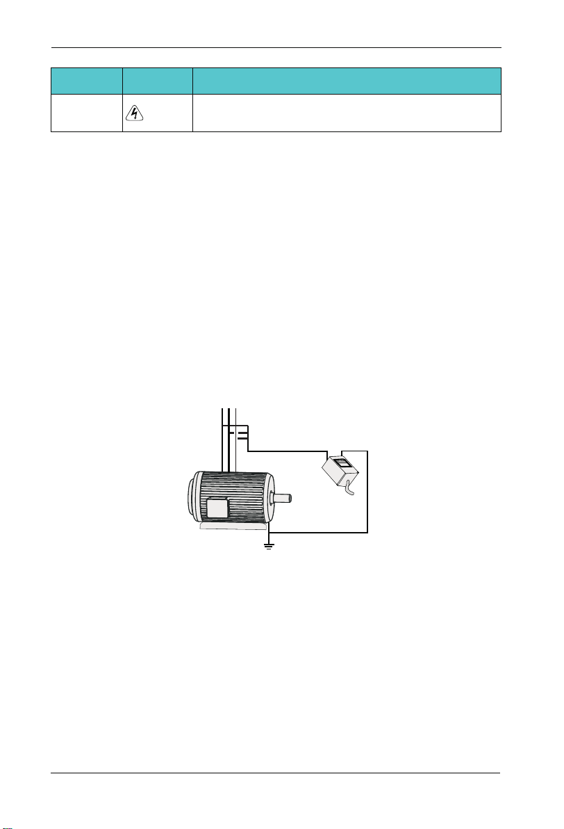
1.3.2 Motor Insulation Test
Perform the insulation test when the motor is used for the first time, or when it is reused
after being stored for a long time, or in a regular check-up, in order to prevent the poor
insulation of motor windings from damaging the AC drive during the insulation test. A 500-V
mega-Ohm meter is recommended for the test. The insulation resistance must not be less
than 5 MΩ.
UVW
Input terminals of the motor
Megger
Ground
1.3.3 Thermal Protection of Motort
If the selected AC drive does not match the rated capacity of the motor , especially when
the rated power of the AC drive is higher than that of the motor, adjust the parameters for
motor protection in the AC drive or to install thermal relay to protect the motor .
1.3.4 Running Below and Above Rated Frequency
The AC drive provides frequency output of 0 to 600.00Hz. When the users use the
frequency converter for a long time, please pay attention to the motor cooling or use of
variable frequency motor. If the AC drive is required to run at over 50Hz, consider the
capacity of the machine.
-1 0-
SD200 User Manual
1.3.5 Vibration of mechanical device
The AC drive may encounter the mechanical resonance point at some output frequencies,
which can be avoided by setting the skip frequency. If the operating frequency of the cus-
tomer coincide with the resonant frequency please modify the operating frequency or
change the inherent resonance frequency of the mechanical system.
1.3.6 Motor heat and noise
The output of the AC drive is pulse width modulation (PWM) wave with certain harmonic
frequencies, and therefore, the motor temperature, noise, and vibration are slightly greater
than those when the AC drive runs at power frequency (50 Hz).
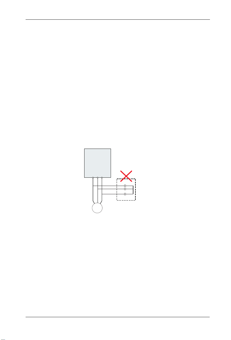
1.3.7 Voltage-sensitive device or capacitor on output side of the AC drive
Do not install the capacitor for improving power factor or lightning protection voltagesen-
sitive resistor on the output side of the AC drive because the output of the AC drive is PWM
wave. Otherwise, the AC drive may suffer transient overcurrent or even bedamaged.
AC Driver
W
U V
Chapter 1 Safety and Cautions
Capacitor or
voltage-sensitive resistor
M
1.3.8 Contactor at the I/O terminal of the AC drive
When a contactor is installed between the input side of the AC drive and the power supply,
the AC drive must not be started or stopped by switching the contactor on or off. If the AC
drive has to be operated by the contactor, ensure that the time interval between switching
is at least one hour since frequent charge and discharge will shorten the service life of the
capacitor inside the AC drive.
When a contactor is installed between the output side of the AC drive and the motor,do not
turn off the contactor when the AC drive is active. Otherwise, modules inside the AC drive
may be damaged.
-11 -

Chapter 1 Safety and Cautions
SD200 User Manual
Contactor KM
380Vac
50/60Hz
Do not start/stop the AC drive by
switching the contactor on/off. If
the AC drive has to be operated
by the contactor, ensure that the
tiome interval is at least one hour.
R
S
AC Driver
T
Contactor KM or
offer sw itche s
U
V
W
Turn on /off the contactor
when the AC drive has no
output. Otherwise,modifies
inside the AC drive may be
damaged.
M
1.3.9 The Use Occasion of the External Voltage Out of Rated Voltage Rage
The AC drive must not be used outside the allowable voltage range specified in this
manual. Otherwise, the AC drive’s components may be damaged. If required, use a
corresponding voltage step[-up or step-down device.
1.3.10 The Above Derating of the Default
Different power grade frequency converter has its default carrier frequency, when to run at
a higher carrier frequency, the AC Drive must to reduce the amount when running.
1.3.11 Change Three Phase Input into Two Phase Input
It is not allowed to change the three phase AC drive into two phase one . Otherwise , it
may cause it may cause fault or damage the AC drive.
1.3.12 The Protection of the Lighting Impulse
Although the AC drive has equipped with lightning overvoltage, overcurrent device, which
has a certain protection function for the induction lightining. For the lightning prone areas,
the user is necessary to install lightning protection device at the front of the AC drive, which
will benefit to the service life of the transducer.
1.3.13 Ambient Temperature and De-rating
The normal use of the frequency converter ambient temperature is -10℃ ~40℃ .
Temperature exceeds 40℃ , the equipment need to reduce the amount of use. The ambient
temperature of each increase is reduced by 1.5%, the maximum use of the ambient
temperature is 50℃ .
1.3.14 Altitude and Derating
In places where the altitude is above 1000m and the cooling effect reduces due to thin airit
is necessary to de-rate the AC drive. Contact Our company for technical support.
1.3.15 Some Special Usages
If writing that is not described in this manual, such as common DC bus is applied, contact
the agent or Our company for technical support.
-1 2-

SD200 User Manual
Chapter 1 Safety and Cautions
1.3.16 The Cautious of the AC drive Disposal
The electrolytic capacitors on the main circuits and PCB may explore when they are burnt.
Poisonous gas is generated when the plastic parts are burn. Treat them as ordinary
industrial refer to relevant national laws and regulations.
1.3.17 Adaptable Motor
1. The standard parameters of the adaptable motor is adaptable four-squirrel-cage
asynchronous induction motor or PMSM. For other types of motor, select a proper AC drive
according to the rated motor current.
2. The cooling fan and rotor shaft of general AC Drive are coaxial, which results in reduced
cooling effect when the rotational speed declines. If variable speed is required, add a more
powerful fan or replace.
3. The standard parameters of the adaptable motor have been configured inside the AC
drive. It is still necessary to perform motor auto-tuning or modify the default values based
on actual conditions. Otherwise, the running result and protection performance will be
affected.
4. The AC drive may alarm or even be damaged when short-circuit exists on cables or
inside the motor. Therefore, perform insulation short-circuit test when the motor and cables
are newly installed or during routine maintenance. During the test, make sure that the AC
drive is disconnected from the tested parts.
-1 3-

-1 4-

Chapter 2
Product Information
2.1 Chapter of This Content
This chapter briefly introduces the operation principle, product features, layout, namepl-ate,
and type of instruction.
2.2 Basic Principle
SD200 is a kind of AC drive used to control asynchronous AC induction motor.
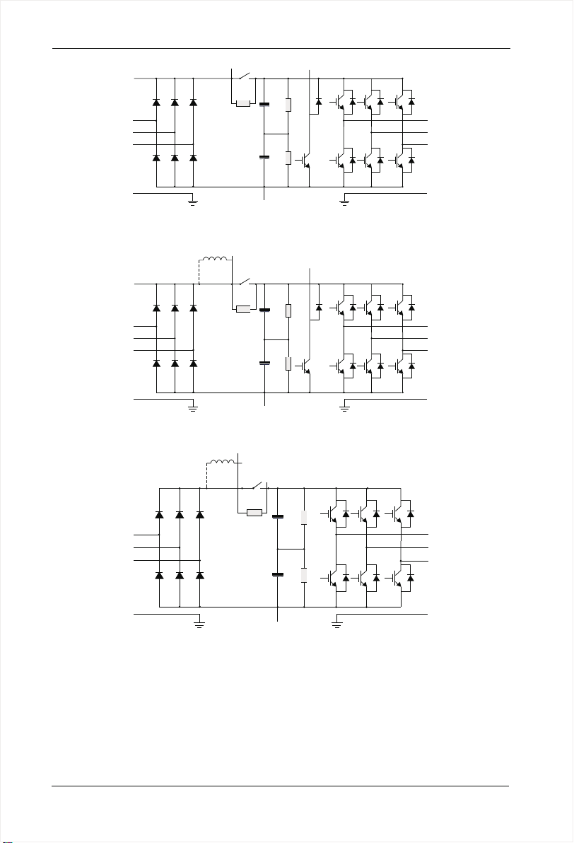
The following figure shows the AC drive main circuit diagram. Rectifie make three-phase
AC voltage into DC voltage. Capacitor groups of intermediate circuit stabilize the DC
voltage .The AC drive converts of the DC voltage to AC voltage for AC motor use. When
the voltage in the circuit exceeds the maximum limit, the braking pipe will connect an
external braking resistor to the intermediate DC circuit to consume the feedback energy.
-1 5-
Chapter 2 Product Information
SD200 User Manual
R
S
T
PE
P+
P-
PB
Figure 2-1 Main Circuit Diagram( less than 18.5 kw (including))
DC reactor
R
S
T
PE
P+
P
P-
PB
Figure 2-2 Main Circuit Diagram (22kw~30kw)
DC reactor
P+
U
V
W
PE
U
V
W
PE
P
R
S
T
PE
P-
U
V
W
PE
Figure 2-3 Main Circuit Diagram (over 30kw)
Note:
Higher than 22kw AC drive (including) support for external DC reactor, before
1.
connecting, it need to take down the bronze between P and P +. 1.
2. Lower than 30kw AC drive (including) support for external braking resistor, higher than
37kw AC drive (including) support for external braking unit , braking resistor.
-1 6-
SD200 User Manual
Chapter 2 Product Information
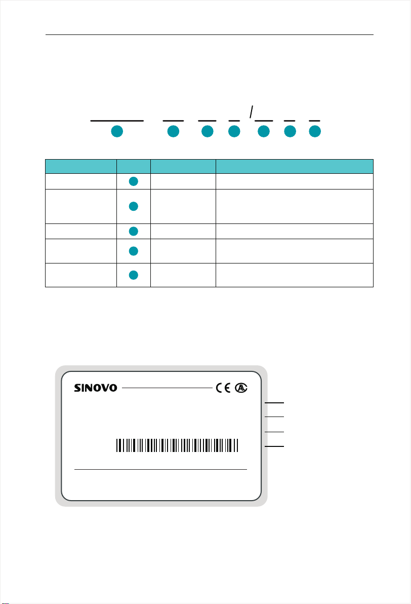
2.3 Naming Rules
In the model code contains the product information Users can find the code from the
transducerand simple nameplate.
SD200
Field Mark
Ac drive series
Voltage Level
Adaptive Power
Function Type
braking Unit
1
1
2
3
4
5
4T
-
2 4
Explanation
Ac drive series
Voltage Level
Adaptive Power
Function Type
braking Unit
Figure 2-4 Name Designation Rules
2.4 Nameplate
MODEL: SD200-4T-5.5 G/ 7. 5P C
INPUT: AC3PH 380V 50/60Hz 14. 6A /2 0. 5A
OUTPUT: AC3PH 380V 0 600Hz 13A/17A~
S/N: FDLAGCA0A040
11
-
3 3
G
15
P
C
4
Content
Sinodrive200 abbreviated SD200
2S:single-phase 220V
2T:Three-phase 220V
4T:Three-phase 380V
0.7KW~500KW
G:General
P:Fan pump
NullC::None
Only braking unit
Model of the AC drive
Rated input voltage,
frequency and current
Rated output voltage,
frequency and current
Bar code
5
SHENZHEN SINOVO ELECTRIC TECHNOLOGIES CO.,LTD.
Figure 2-4 Name Designation Rules
MADE IN C HINA
-1 7-
Chapter 2 Product Information
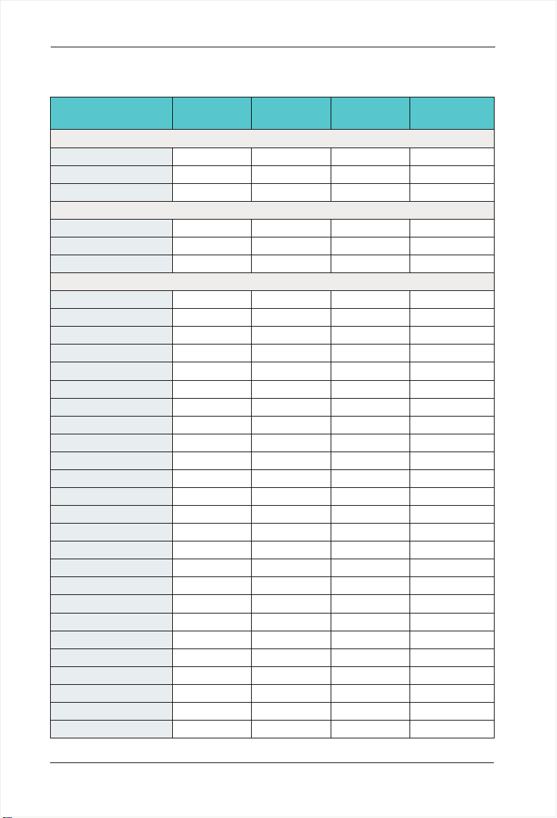
2.5 SD200 Series of AC drive
SD200 User Manual
Model
SD200-2S-0.7G
SD200- -1.52S G
SD200- -2.22S G
SD200-2T-0.7G
SD200- -1.52T G
SD200- -2.22T G
SD200-4T-0.7G
SD200-4T-1.5G
SD200-4T-2.2G
SD200-4T-4.0G
SD200-4T-5.5G
SD200-4T-7.5G
SD200-4T-11G
SD200-4T-15G
SD200-4T-18.5G
SD200-4T-22G
SD200-4T-30G
SD200-4T-37G
SD200-4T-45G
SD200-4T-55G
SD200-4T-75G
SD200-4T-90G
SD200-4T-110G
SD200-4T-132G
SD200-4T-160G
SD200-4T-185G
SD200-4T-200G
SD200-4T-220G
SD200-4T-250G
SD200-4T-280G
SD200-4T-315G
Power Capacity
(KVA)
Single-phase 220V Range:-15%~20%
1.5
3.0
4.0
Three-phase 220V Range:-15%~20%
1.5
3.0
4.0
Three-phase 380V Range:-15%~20%
1.5
3.0
4.0
5.9
8.9
11
17
21
24
30
40
57
69
85
114
134
160
192
231
255
287
311
355
396
439
Input Current
(A)
8.2 0.754.7 0.75
14.0 7.5
23.0
5.5 0.754.7 0.75
7.7 7.5
12.0
3.4 0.752.3 0.75
5.0 3.7
5.8
10.5 8.5 4.0
14.6 13
20.5
26.0 25 11
35.0 32
38.5 37 18.5
46.5 45
62.5 60 30
76.0
92.0 91 45
113
157
180 176 90
214
256 253 132
307 304 160
333 330 185
380 377 200
429 426 220
470 465 250
525 520 280
605 600 315
Output Current
Adaptable Motor
(A)
10.0
10.0
5.1
17 7.5
75
112
150
210 110
(KW)
1.5
2.2
1.5
2.2
1.5
2.2
5.5
15
22
37
55
75
-1 8-
SD200 User Manual
Chapter 2 Product Information
Model
SD200-4T-400G
SD200-4T-450G
SD200-4T-500G
Power Capacity
(KVA)
479
530
600
660
Input Current
(A)
Output Current
(A)
665 660 350SD200-4T-350G
730 725 400
825 820 450
910 900 500
Adaptable Motor
(KW)
Note:
1. 0.75 ~ 315 kw AC drive input current is the measured results, which under the condition
of input voltage 380V, and without DC reactor as well as input and output reactor;
2. 350 ~ 500 kw AC drive input current is the measured results, which under the condition
of input voltage 380V, and equipped with input reactor;
3. Rated output current is defined as the output current of the output voltage 380V.
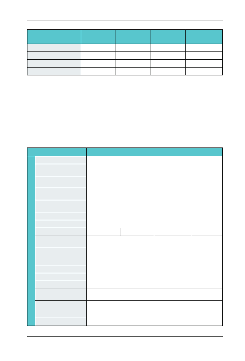
2.6 Technical Specifications
Item
Maximum frequency
Carrier frequency
Input frequency
resolution
Control mode
Speed range
Overload capacity
Basic Function
Torque boost
V/F curve
Accelerate/
Decelerate curve
DC braking
Jog control
Simple PLC Multi-speed
Onboard PID
Auto voltage
regulation (AVR)
Overvoltage/overcurrent
stall control
Rapid current limit
0~600Hz
2.0kHz~16.0kHz; The carrier frequency is automatically adjusted
based on the load features.
Digital setting: 0.01Hz
Analog setting : Maximum frequency x 0.025%
0:V/F control
1:Vector control 0 mode
1:50(vector control 0 mode)
G type:150% rated current for 60s
Line or S-curve Acc/Dec mode, four kinds of Acc/Dec time Range of
Acc/Dec time 0.0~6000.0s
DC braking frequency : 0.00Hz to Maximum frequency
braking time: 0.0 to 100.0s
braking current : 0.0 to 150%
Jog frequency range: 0.00Hz~F00.03Maximum frequency
16-speed operating through built-in PLC or control terminal
It realizes process-controlled closed loop control system easily.
Jog frequency range: 0.00Hz~Maximum frequency
The current and voltage are limited automatically during
the running process so as to avoid frequent tripping due to
overvoltage/overcurrent.
It helps to avoid frequent over- current faults of the AC drive.
Specification
Auto torque boost
Line
Multi-point
P type: 110% rated current for 60s
Manual torque boost: 0.1%~20.0%
Square V/F curve
VF separation
-1 9-

Chapter 2 Product Information
SD200 User Manual
Non stop function
Speed tracking start
Freatures
Rapid current limit
Timing Control
Multi-motor switch
Bus Support
Motor overheating
protection
Command source
Frequency source
Auxiliary frequency
source
Running
Input terminal
Output terminal
LED display
The key lock and
Display and
function selection
operation
Protection function
Protection function
Accessories
Item
Virtual IO
Specification
Load feedback energy compensates the voltage reduction so that
the AC drive can continue to run in a short time in case of power
interruption.
Identify the speed of rapidly rotating motor to realize a smooth start
without any rush.
Rapid software and hardware current limiting technology helps to
avoid frequent over-current fault.
Four sets of virtual DO, five groups of virtual DI, enables easy logic
control.
Timing control: set the time range 0.0Min~6500.0Min
Two independent motor parameters enable two motors switching
control
Two independent Modbus communication, profibus-DP
Optional IO expansion card 1, analog input AI5 acceptable the input
of motor temperature sensor .(PT100,PT1000)
Given the control panel, control terminal, serial communication port
given. It can be switched by a variety of ways.
12 frequency sources: digital setting, analog voltage setting, analog
current setting, pulse setting and serial port. It can be switched by a
variety of ways.
12 auxiliary frequency source. Flexible implementation of auxiliary
frequency tuning, frequency synthesis.
Standard:
. Six digital input terminals, one of which support to 50kHz high speed pulse input
. Three analog input terminals, two of which supports -10V~10V
voltage input
. One support 0 ~ 10V voltage input or 0 ~ 20mA current input
Expansion capability:
. Two digital inputs
. One analog input terminal, support 0-10.00V 0-20mA input, and
( )
supports PT100 / Pt1000
Standard:
. One high-speed pulse output terminal (optional open collector
type), support of 0 ~ 50kHz square wave signal output
. One digital output terminal
. Two relay output terminals
. Two analog output terminals, support 0~20mA current output or
0~10V voltage output
Display each parameter of function code group
Achieve some or all of the keys locked and define the scope of
partial keys to prevent misuse.
Powered motor short circuit test; Input/output phase failure protec
tion; Over current protection; voltage protection; Under voltage pr
otection; Over heat protection ; Overload protection; braking resis
tor fault protection.
Brake unit, Simple IO expansion card, Multi-functional IO expansion
card
-
-
-
-2 0-

SD200 User Manual
Chapter 2 Product Information
Item
Application environment
Environment
Altitude
Ambient temperature
Humidity
Vibration
Storage temperature
Specification
In-door, free from direct sunlight, dust, corrosive gas, combustible
ga , oil mist, steam , water drop and salt .
Lower than 1000m (1000m-3000m for derated use)
-10℃+40℃ (derated use in the ambient temperature of 40℃ to 50 ℃ )
Less than 95%RH, without condensation
Less than 5.9m/s(0.6g)
-20℃~+60℃
-2 1-
Chapter 2 Product Information
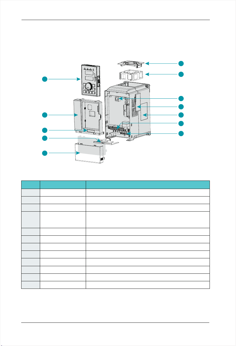
2.7 Structure diagram
2.7.1 The following figure shows the layout of the AC drive
( 2.2KW,for example).
SD200 User Manual
1
8
9
10
11
12
No
1
2
3
4
5
6
7
Main circuit terminals
8
9
10
11
12
Name
Fan-cover
Cooling fan
Keypad interface
Vents-cover
Nameplate
Control terminals
Keypad
Cabinet-cover
Series Label
Apron
Lower-cover
Figure 2-6 Product structure diagram
Description
Protection fan.
Refer to 8.1 " Definition of Related Terms."
It is used to connect the Keypad.
Optional. with the vents-cover installed, the protection level will
increase and the AC drive internal temperature will increase as
well so please derating use the AC drive.
Refer to 2.4 "Nameplate"
Refer to 3.3 "Standard Wiring."
."
Refer to 3.3 "Standard Wiring."
Refer to chapter4 "Operation, Display and Application Examples."
Protect the internal components.
Refer to 2.3 "Naming Rules".
Convenient input and output wiring.
Protect the internal components.
2
3
4
5
6
7
-2 2-
SD200 User Manual
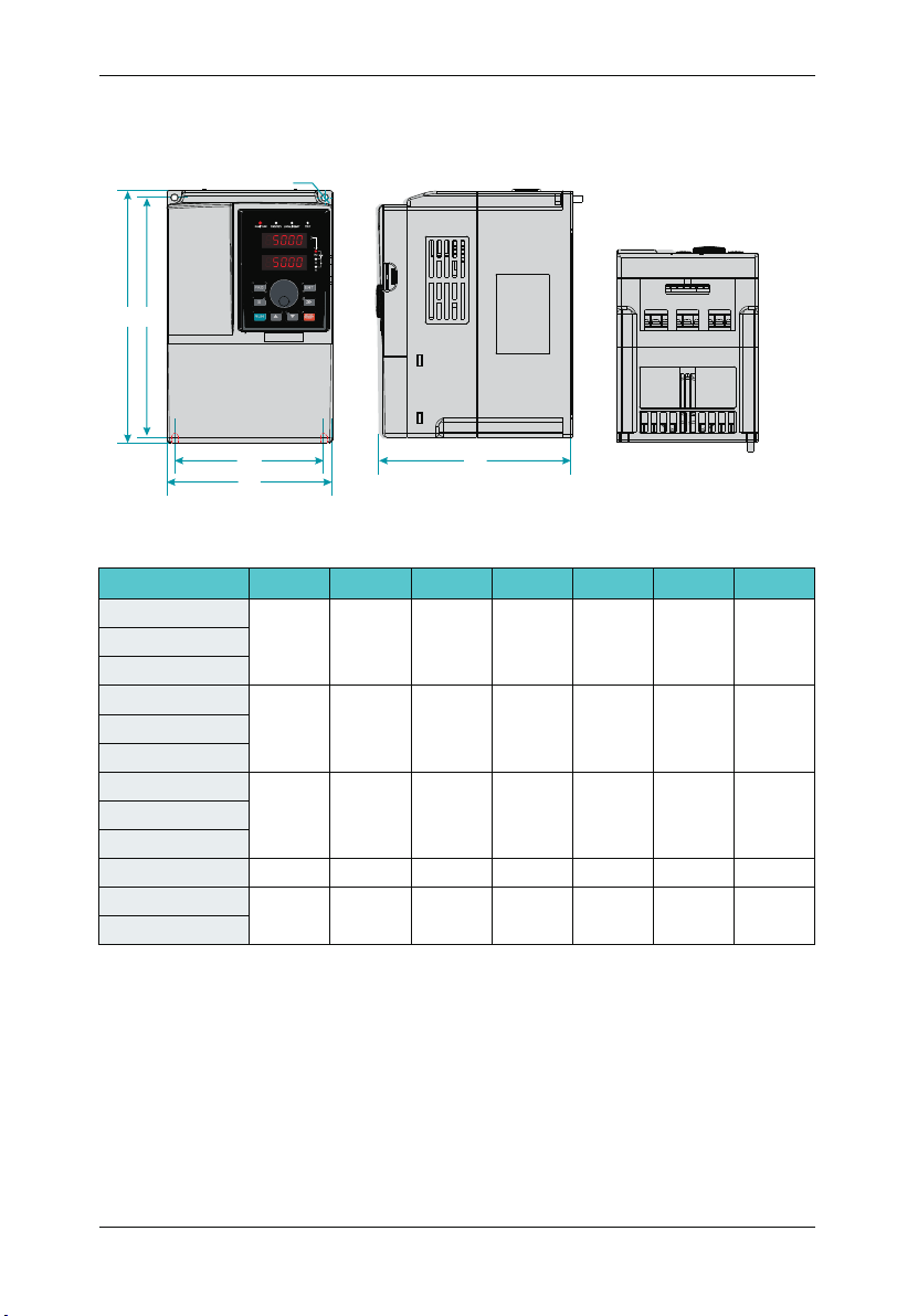
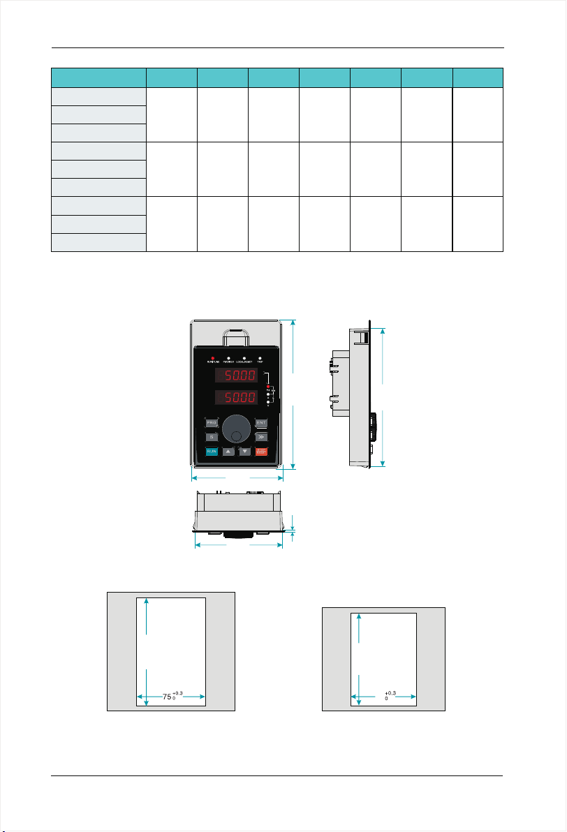
2.7.2 Product Outline, Installation Hole Size
2.7.2.1 SD200 series less than7.5KW (including 7.5KW)
Ø
H
H1
Chapter 2 Product Information
W1
W
D
Figure 2-7 Less than 7.5 KW AC drive installation dimensions and installation size
AC drive model
H(mm) W(mm) D(mm)
H1(mm) W1(mm)
D
SD200-2S-0.7G
SD200-2 -1.5S G
190 110 150 178 98
SD200-2 -2.2S G
SD200-2T-0.7G
SD200-2T-1.5G
190 110 150 178 98
SD200-2T-2.2G
SD200-4T-0.7G
SD200-4T-1.5G
190 110 150 178 98
SD200-4T-2.2G
SD200-4T-4.0G
SD200-4T-5.5G
SD200-4T-7.5G
210 130 160 198 118
250
155
176 236
141
iameter
(mm)
Ø5
Ø5
Ø5
Ø5
Ø5
GW(kg)
2.4
2.4
2.4
3.5
4.5
-2 3-

Chapter 2 Product Information
2.7.2.2 SD200 Series 11KW~45KW
SD200 User Manual
H
W1
W
Figure 2-8 11kw~45kw AC drive installation dimensions and installation size
AC drive model
SD200-4T-11G
SD200-4T-15G
SD200-4T-18.5G
SD200-4T-22G
SD200-4T-30G
SD200-4T-37G
SD200-4T-45G
H(mm) W(mm) D(mm)
285
332
387
170 162 270
220
250 220 373
270 252 426 22.5440
2.7.2.3 SD200 Series 55KW~110KW
H
H1
D
D
H1(mm) W1(mm)
214
318
135
140
150
iameter
(mm)
Ø6
Ø7
GW(kg)
6.5
10.3
13
15
180
H1
Fig 2-9 55~110KW AC drive installation dimensions and installation size
AC drive model
SD200-4T-5 G5
SD200-4T-75G
SD200-4T-90G
SD200-4T-110G
W1
W
H(mm) W(mm) D(mm)
550
650
300 258 534 200
370 282 625 250
-2 4-
D
H1(mm) W1(mm)
iameter
D
(mm)
Ø9
GW(kg)
35.6
53
54
55
SD200 User Manual
2.7.2.4 SD200 Series 132KW~185KW
H
H1
Chapter 2 Product Information
W1
W
D
Figure 2-10 132KW~185KW AC drive installation dimensions and installation size
AC drive model
H(mm) W(mm) D(mm)
H1(mm) W1(mm)
SD200-4T-132G
880 485 31 0 860 320
SD200-4T-185G
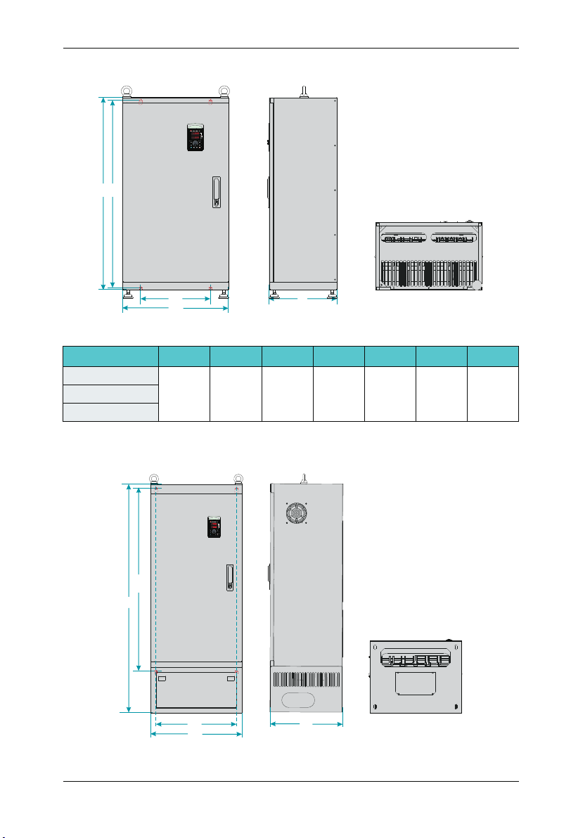
2.7.2.5 SD200 Series 200KW~500KW
H1
H
D
iameter
(mm)
Ø13
GW(kg)
99SD200-4T-160G
W1
W
D
Figure 2-11 200KW~500KW AC drive installation dimensions and installation size
-2 5-
Chapter 2 Product Information
AC drive model
H(mm) W(mm) D(mm)
H1(mm) W1(mm)
SD200-4T-200G
SD200-4T-220G
1250 500 400 1000 440
SD200-4T-250G
SD200-4T-280G
SD200-4T-315G
1350 650 400 1105 513
SD200-4T-350G
SD200-4T-400G
SD200-4T-450G
1810 850 405 1410 513
SD200-4T-500G
2.7.3 External Keypad Installation Dimensions
SD200 User Manual
iameter
D
(mm)
Ø13
Ø13
Ø13
GW(kg)
167
206
415
79.00
74.80
Figure 2-12 Keypad Installation dimensions
+0. 3
0
119. 5
Figure 2-13
Opening dimension diagram
for keypad with base
-2 6-
128.20
1.50
+0. 3
0
100
70
Figure 2-14
Opening dimension diagram
for keypad without base
119.00
SD200 User Manual
Chapter 2 Product Information
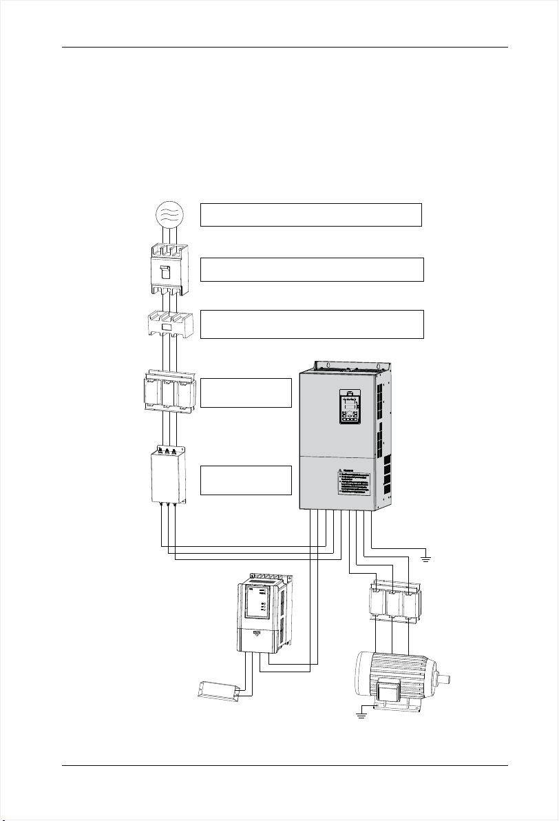
2.8 Peripheral Electrical Components System Structure
When using SD200 series AC drive to control asynchronous motor system, you have to
install various electrical components on the side of input and output of the AC drive to
guarantee the stability and safety of system.In addition, SD200 series AC drive is equipped
with a variety of optional accessories and expansion card to achieve various functions.
More than 37kw series three-phase 380v system structure as shown in the figure
below(The figure AC drive terminal refer to 55~110KW):
3-phase AC
power supply
Moulded case
circuit breakeror
earth leakage
circuit breakers
Electromagnetic
contactor
AC reactor
Input side EMC
filter
Use within the allowable power supply specification
of the AC drive
Select a proper breaker to resistlarge in-rush current
that flows into the AC drive at power-on
To guarantee safety, use an electromagnetic contactor.
Do not use it to start or stop the AC drive because such
operation reduces the service life of the AC drive
Suppress the high
order harmonic to
improve power factor
AC Driver
Reduce the electrom
agnetic interference
on the input side.
Break unit
-
P
P+
R
P-
S
T
U
V
W
PE
Ground
Output reactors
PB
P
P+
Braking resistor
BR
P+
P-
Ground
Motor
Figure 2-15 Under 37 kw series 3-phase 380 V system structure diagram
-2 7-

Chapter 2 Product Information
2.8.1 Peripheral Electrical Components Description
SD200 User Manual
Accessory
Name
MCCB
Contactor
AC input
reactor
EMC input
filter
DC reactor
AC output
reactor
Installation
position
Power
receiving side
Between MCCB
and the AC drive
input side
AC drive
input side
AC drive
input side
S 200 series
D
AC drive of
200G and above
configured
with DC reactor
as standard
Between the AC
drive output side
and the motor,
close to the AC
drive
Function Description
Interrupt the power supply when overcurrent occurs on
ª
downstream devices.
Start and stop the AC drive.Do not start and stop the AC
ª
drive frequently by switching the contactor on and off (less
than twice per minute) nor use it to directly start the AC
drive.
Improve the power factor of the input side;
ª
Eliminate the higher harmonics of the input side effecti-vely
ª
and prevent other devices from being damaged due
to distortion of the voltage waveform;
ª
Eliminate the input current unbalance due to unbalance
ª
between the power phases;
Reduce the external conduction and radiation interfere-
ª
nce of the AC drive;
ª
Decrease the conduction interference flowing from the
ª
power end to the AC drive and improve the anti-interfe-
ª
rence capacity of the AC drive.
ª
Improve the input power factor;
ª
Improve the efficiency and thermal stability of the AC drive;
ª
Eliminate the impact of higher harmonics of the AC drive
ª
input side and reduce the external conduction and
radiation interference.
The output side of the AC drive generally has much higher
ª
harmonics. When the motor is far from the AC drive, there
is much distributed capacitance in the circuit and certain
harmonics may cause resonance in the circuit, bringing
about the following two impacts:
a.Degrade the motor insulation performance and damage
ª
the motor in the long run.
b.Generate large leakage current and cause frequent AC
ª
drive protection trips.
If the distance between the AC drive and the motor is
ª
greater than 100 m, install an AC output reactor.
-2 8-

SD200 User Manual
Chapter 2 Product Information
Note:
Do not install capacitor or surge suppressor on the output side of the AC drive. Otherwise, it
1.
may cause faults to the AC drive or damage to the capacitor and surge suppressor;
2. Input/output (main circuit) of the AC drive include harmonic components, which may interfere
with the AC drive attachment communications equipment. Therefore, install an anti-aliasing filter
to minimize the interference;
3. Details of peripherals and options refer to Chapter 2 selection of peripheral devices.
2.8.2 Peripheral electrical components selection guidance
AC Drive model
SD200-2S-0.7G
SD200-2 -1.5S G
SD200-2 -2.2S G
SD200-2T-0.7G
SD200-2T-1.5G
SD200-2T-2.2G
SD200-4T-0.7G
SD200-4T-1.5G
SD200-4T-2.2G
SD200-4T-4.0G
SD200-4T-5.5G
SD200-4T-7.5G
SD200-4T-11G
SD200-4T-15G
SD200-4T-18.5G
SD200-4T-22G
SD200-4T-30G
SD200-4T-37G
SD200-4T-45G
SD200-4T-5 G5
SD200-4T-75G
MCCB(A)
100
100
125
160
200
250
210
Recommended
contactor
Single phase 220V
16
20
32
16
25
25
10
16
16
25 16 4.0 4.0 1.0
32 25 4.0 4.0 1.0
40 30 4.0 6.0 1.0
63
63
10
16
20
Three phase 220V
10
16
16
380VThree phase
6
10
10
40
40
63
63
100
100
125
160
160
Recommended
input side main
circuit wire mm2
2.5
4.0
6.0
2.5
4.0
4.0
2.5
2.5
2.5
4.0
6.0
10
16
16
25
50
60
6
Recommended
output side main
circuit wire mm2
2.5
2.5
4.0
2.5
2.5
4.0
2.5
2.5
2.5
6.0
10
10
10
16
25
25
35
50
Recommended
control loop
wire mm2
1.0
1.0
1.0
1.0
1.0
1.0
1.0
1.0
1.0
1.0
1.0
1.5
1.5
1.5
1.5
1.5
1.5
1.5
-2 9-
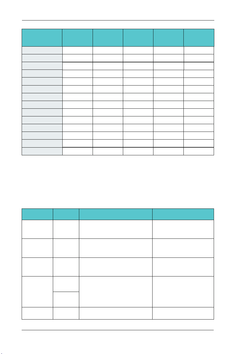
Chapter 2 Product Information
SD200 User Manual
AC Drive model
SD200-4T-90G
SD200-4T-110G
SD200-4T-132G
SD200-4T-160G
SD200-4T-185G
SD200-4T-200G
SD200-4T-220G
SD200-4T-250G
SD200-4T-280G
SD200-4T-315G
SD200-4T-350G
SD200-4T-400G
SD200-4T-450G
SD200-4T-500G
MCCB(A)
250
350
400
500
600
600
600
800
800 800 185*2 185*2
1000 800 150*3 150*3
1000 800 150*4 150*4
1200
1200
1600
Recommended
contactor
160
350
400
400
400
600
600
600
1000
1000
1000
Recommended
input side main
circuit wire mm2
70
120
150
185
185
150*2
150*2
185*2
150*4
150*4
150*4
Recommended
output side main
circuit wire mm2
50
120
150
185
185
150*2
150*2
185*2
150*4
150*4
150*4
Recommended
control loop
wire mm2
1.5
1.5
1.5
1.5
1.5
1.5
1.5
1.5
1.5
1.5
1.5
1.5
1.5
1.5
2.9 SD200 Optional Parts
Peripheral optional braking unit, each function expansion card and the outer lead operator,
etc..As shown below. Seeing detailed usage instructions for use of the accessory. For the
following options, please note when ordering.
Internal
braking unit
External
braking unit
Multi-function
I/O expansion
card
Modbus
communication
card
Profibus-DP
card
Type
Models
followed
by letter "C”
SDBUN
SDIO
SDRS485
SDCAN
SDDP
Function
Models power under 22KW are
installed with the internal braking
unit as standard configuration
37KW and above need to be
configured with an external
braking unit
Increase 3 digital inputs, 2 digital
outputs, two relay outputs, two
analog voltage input T_Motor
One RS - 485 communication
card, one CAN communication
card.
Profibus-DP card DB9interface,
-3 0-
RemarkName
For 30KW model power,
the braking unit is optional
Multiple braking ones are
connected in parallel for
the models above 90KW
It applies to all models
It applies to all models
It applies to all models
 Loading...