

Sinovo SD200-2T-0.7G, SD200-2T-1.5G, SD200-2S-1.5G, SD200-2S-0.7G, SD200-2S-2.2G User Manual
...Page 1
SD200 AC Drive Us er Man ua l (Ve rs io n: V 3. 1)
AC DRIVE
Open-loop Vector Type
SD
002
AC DRIVE
User Manual
<
>
1
0
0
0
C
Z
E
Version: V3.1
Page 2

Preface
SD200 User Manual
Unpacking Inspection Cautions
Every AC Drive have been tested strictly in factory prior to shipment. Upon unpacking,
check:
ªWhether the product is damaged;
ªWhether the nameplate of model and AC drive ratings are consistent with your order.
ªWhether the box contains the AC driv e, cert ificate of con formity, use r manua l and
warranty card. If you find any omiss ion or damage, contact Our company or your
supplier i mmediately.
First-time Use
For the users who use this product for the first time, read the manual carefully. If in doubt
concerning some functions or performances, contact the technical support personnel of
Our company to ensure correct use.
S 200 series AC drives have passed CE test and also meet the
D
require ments of following International Standard.
ªIEC/EN 61800-5-1:2003 Safety requirements for adjustable speed electric drive systems.
ªIEC/EN 61800-3:2004 adjustable speed electric drive systems:(The third par)the
electromagnetic compatibility standard of the product and its specific test method.
ªIEC/EN 61000-2-1,2-2,3-2,3-3,4-2,4-3,4-4,4-5,4-6:EMC International and EU Standards.
ªThe instructions are subject to change, without notice, due to product upgrade,
specification modification as well as efforts to increase the accuracy and convenience of
the manual.
-
-2 -
Page 3

SD200 User Manual
Contents
Contents
Preface.................................................................................................................01
Contents..............................................................................................................03
Chapter 1 Safety and Cautions.........................................................................07
1.1 Safety and Cautions Definition
1.2 Safety Cautions.........................................................................................08
1.3 Precautions...............................................................................................10
Chapter 2 Product Information.........................................................................15
2.1 Chapter of This Content................................................. ......... .........
2.2 Basic Principle...........................................................................................15
2.3 Naming Rules............................................................................................17
2.4 Nameplate.................................................................................................17
2.5 SD200 Series of AC drive.........................................................................18
2.6 Technical Specifications............................................................................19
2.7 Structure Diagram.....................................................................................22
2.8 Peripheral Electrical Components System Structure................................27
2.9 SD200 Optional Parts...............................................................................30
2.10 Connection Methods...............................................................................32
..................................................................07
. ........ 15
Chapter 3 Mechanical and Electrical Installation............................................35
3.1 Chapter of This Content......................................................... ...........35
3.2 Mechanical Installation..............................................................................36
3.3 Standard Wiring........................................................................................41
3.4 Layout Protection......................................................................................51
........
Chapter 4 Operation, Display and Application Examples..............................53
4.1 Chapter of this Content............................... ......... ................53
4.2 Introduction of the Keypad........................................................................54
4.3 Display of Keypad.....................................................................................56
4.4 Keypad Operation.....................................................................................57
............. ........
Chapter 5 Function Parameter Table................................................................59
5.1 Chapter of this Content.......................................................... ...........59
5.2 Function Parameter Table.........................................................................60
........
-3 -
Page 4

Contents
SD200 User Manual
Chapter 6 Parameter Description.....................................................................91
Group F00: Basic Function Group........................... .................. ......92
Group F01: Start-stop Control Group..............................................................99
Group F02: Motor 1 Parameter Group..........................................................104
Group F04: V/Fcontrol Group........................................................................107
Group F05: Input Terminal Group..................................................................113
Group F06: Output Terminal Group...............................................................121
Group F07: HMI Group.................................................................................127
Group F08: Strengthen the Functional Groups.............................................133
Group F09: PID Control Group.....................................................................143
Group F0A:Wobble, Length, Count and Timing Parameter Group..........,....153
Group F0B: Simple PLC and Multi-speed Control Group.............................156
Group F0C: Protection Parameter Group.....................................................160
Group F0D: Motor 2 Parameter Group.........................................................165
Group F0E: Serial Communication Function Group......................................167
Group A01: A1 Curve Setting Function Group..............................................170
Group A02: Status Check Function Group....................................................173
Group A03: DP Parameters Group...............................................................175
.. ..........,..
Chapter 7 EMC..................................................................................................185
7.1 .............................................. ..........186
Definition of Related Terms .............
7.2 EMC Standard Introduction.....................................................................186
7.3 Selection of Peripheral EMC Devices.....................................................187
7.4 Shielded Cable........................................................................................191
7.5 Requirement for Leakage Current..........................................................193
7.6 Solutions to Common EMC Interference Problems................................194
Chapter 8 Troubleshooting and Maintenance...............................................195
Daily Repair and Maintenance ................................ .. ........
8.1 ...... .. ...... ........196
8.2 Warranty Agreement...............................................................................197
8.3 Contents of This Chapter........................................................................197
8.4 Alarm and Fault Inductions......................................................................198
8.5 Fault Reset..............................................................................................198
8.6 Fault History............................................................................................198
8.7 Fault Instruction and Solution..................................................................198
8.8 Common Fault Analysis..........................................................................203
-4 -
Page 5

SD200 User Manual
Contents
Chapter 9 Communication Protocol...................................................................209
9.1 Networking Mode............................................................ ..................209
9.2 Interface Mode........................................................................................210
9.3 Protocol Frame Format...........................................................................210
9.4 Function Protocol....................................................................................211
9.5 Communication Parameters Address.....................................................214
......
Warranty Agreement
Product warranty card
-5 -
Page 6

-6 -
Page 7

Chapter 1
Safety and Cautions
1.1 Safety and Cautions Definition
Read this manual carefully so that you have a thorough understanding. Installation,
commissioning or maintenance may be performed in conjunction with this chapter. Our
company will assume no ability and responsibility for any injury or loss caused by improper
operation.
Danger
Operations which are not performed comply with the requirements may cause severe hurt
or even death.
Note
Operations which are not performed comply with requirements may cause personal injury
or property damage.
-7 -
Page 8
Chapter 1 Safety and Cautions
1.2 Safety Cautions
SD200 User Manual
Use Stage Safety Grade
Danger
Before
Installation
Danger
Danger
During
Installation
At wiring
Danger
Note
Precautions
Do not install the equipment if you find water seepage,
ª
component missing or damage upon unpacking.
Do not install the equipment if the packing list does not
ª
conform to the product you received.
Handle the equipment with care during transportation to
ª
prevent damage to the equipment.
Do not use the equipment if any component is damaged or
ª
missing. Failure to comply will result in personal injury.
Do not touch the components with your hands. Failure to
ª
comply will result in static electricity damage.
Install the equipment on incombustible objects such as
ª
metal, and keep it away from combustible materials.
Failures to comply may result in a fire.
Do not loosen the fixed screws of the components,
ª
especially the screws withe red marks.
Do not drop wire end or screw into the AC drive. Failure it
ª
will result in damage to the AC drive.
Install the AC drive in places free of vibration and direct
ª
sunlight.
When two AC drives are laid in the same cabinet ,arrange
ª
the installation positions properly to ensure the cooling
effect.
A circuit breaker must be used to isolate the power supply
ª
and the AC drive. Failure to comply may result a fire.
Ensure that the power supply is cut off before wiring. Failure
ª
to comply may result in electric shock.
Never connect the power cables to the output
ª
terminals(U,V,W) of the AC drive. Pay attention to the
marks of the wiring terminals and ensure correct wiring.
Failure to comply may result in damage to the AC drive.
Ensure that the main cable line comply with the standard,
ª
the line meets the EMC requirements and the area safety
standard. Failure to comply may result in risk or accident.
Never connect the power cables the braking resistor
ª
between the DC bus terminals P+, P-. Failure to comply
may result in a fire.
-8 -
Page 9
SD200 User Manual
Chapter 1 Safety and Cautions
Use Stage Safety Grade
At wiring
Before
Power-on
After
Power-on
Danger
Danger
Danger
Danger
During
Operation
Danger
Precautions
Use a shielded cable for the encoder, and ensure that the
ª
shielding layer is reliably grounded.
Please confirm the peripheral equipment and cable
ª
converter is configured in this manual of the recommended
model, all the configuration line in accordance with the
connection method of the manual provides the correct
wiring. Failure to comply will result in accidents.
Check that the voltage class of the power supply is
ª
consistent with the rated voltage class of the AC drive.
Do not open the AC drive’s cover after power-on. Failure to
ª
comply may result in electric shock.
Do not touch the operation of AC drive during the hands is
ª
wet. Failure to comply will result in accident.
Do not touch any I/O terminal of the AC drive. Failure to
ª
comply may result in electric shock.
Do not change the default settings of the AC drive. Failure
ª
to comply will result in damage to the AC drive.
Do not touch the rotating part of the motor during the motor
ª
auto-tuning or running. Failure to comply will result in
accident.
Signal detection must be performed only by qualified
ª
personnel during operation. Failure to comply will result in
personal injury or damage to the AC drive.
Do not touch the fan or the discharging resistor to check the
ª
temperature. Failure to comply will result in personal burnt.
Avoid objects falling into the AC drive when it is running.
ª
Failure to comply will result in damage to the AC drive.
Do not start or stop the AC drive by turning the contactor
ª
ON/OFF. Failure to comply will result in damage to the AC
drive.
After
Power-on
Danger
Do not repair or maintain the AC drive at power-on. Failure
ª
to comply will result in electric shock.
Ensure that the AC drive is disconnected from all power
ª
suppliers before staring repair or maintenance on the AC
drive.
Repair or maintenance of the AC drive may be performed
ª
only by qualified personnel. Failure to comply will result in
personal injury or damage to the AC drive.
-9 -
Page 10
Chapter 1 Safety and Cautions
SD200 User Manual
Use Stage Safety Grade
After
Power-on
Danger
Set and check the parameters again after the AC drive is
ª
replaced.
Precautions
1.3 Cautions
1.3.1 Requirement on Residual Current Device(RCD)
The AC drive generates high leakage current during running, which flows earthing (PE)
conductor. Thus install a type-B RCD at the transient and steady-state leakage current to
ground that may be generated at startup and during running of the AC drive. You can
select a specialized RCD with the function of suppressing high harmonics or general-
purpose RCD with relatively large residual current.
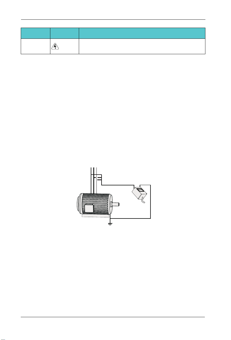
1.3.2 Motor Insulation Test
Perform the insulation test when the motor is used for the first time, or when it is reused
after being stored for a long time, or in a regular check-up, in order to prevent the poor
insulation of motor windings from damaging the AC drive during the insulation test. A 500-V
mega-Ohm meter is recommended for the test. The insulation resistance must not be less
than 5 MΩ.
UVW
Input terminals of the motor
Megger
Ground
1.3.3 Thermal Protection of Motort
If the selected AC drive does not match the rated capacity of the motor , especially when
the rated power of the AC drive is higher than that of the motor, adjust the parameters for
motor protection in the AC drive or to install thermal relay to protect the motor .
1.3.4 Running Below and Above Rated Frequency
The AC drive provides frequency output of 0 to 600.00Hz. When the users use the
frequency converter for a long time, please pay attention to the motor cooling or use of
variable frequency motor. If the AC drive is required to run at over 50Hz, consider the
capacity of the machine.
-1 0-
Page 11
SD200 User Manual
1.3.5 Vibration of mechanical device
The AC drive may encounter the mechanical resonance point at some output frequencies,
which can be avoided by setting the skip frequency. If the operating frequency of the cus-
tomer coincide with the resonant frequency please modify the operating frequency or
change the inherent resonance frequency of the mechanical system.
1.3.6 Motor heat and noise
The output of the AC drive is pulse width modulation (PWM) wave with certain harmonic
frequencies, and therefore, the motor temperature, noise, and vibration are slightly greater
than those when the AC drive runs at power frequency (50 Hz).
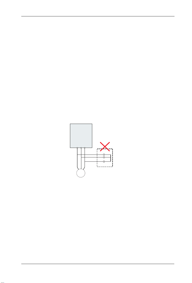
1.3.7 Voltage-sensitive device or capacitor on output side of the AC drive
Do not install the capacitor for improving power factor or lightning protection voltagesen-
sitive resistor on the output side of the AC drive because the output of the AC drive is PWM
wave. Otherwise, the AC drive may suffer transient overcurrent or even bedamaged.
AC Driver
W
U V
Chapter 1 Safety and Cautions
Capacitor or
voltage-sensitive resistor
M
1.3.8 Contactor at the I/O terminal of the AC drive
When a contactor is installed between the input side of the AC drive and the power supply,
the AC drive must not be started or stopped by switching the contactor on or off. If the AC
drive has to be operated by the contactor, ensure that the time interval between switching
is at least one hour since frequent charge and discharge will shorten the service life of the
capacitor inside the AC drive.
When a contactor is installed between the output side of the AC drive and the motor,do not
turn off the contactor when the AC drive is active. Otherwise, modules inside the AC drive
may be damaged.
-11 -
Page 12

Chapter 1 Safety and Cautions
SD200 User Manual
Contactor KM
380Vac
50/60Hz
Do not start/stop the AC drive by
switching the contactor on/off. If
the AC drive has to be operated
by the contactor, ensure that the
tiome interval is at least one hour.
R
S
AC Driver
T
Contactor KM or
offer sw itche s
U
V
W
Turn on /off the contactor
when the AC drive has no
output. Otherwise,modifies
inside the AC drive may be
damaged.
M
1.3.9 The Use Occasion of the External Voltage Out of Rated Voltage Rage
The AC drive must not be used outside the allowable voltage range specified in this
manual. Otherwise, the AC drive’s components may be damaged. If required, use a
corresponding voltage step[-up or step-down device.
1.3.10 The Above Derating of the Default
Different power grade frequency converter has its default carrier frequency, when to run at
a higher carrier frequency, the AC Drive must to reduce the amount when running.
1.3.11 Change Three Phase Input into Two Phase Input
It is not allowed to change the three phase AC drive into two phase one . Otherwise , it
may cause it may cause fault or damage the AC drive.
1.3.12 The Protection of the Lighting Impulse
Although the AC drive has equipped with lightning overvoltage, overcurrent device, which
has a certain protection function for the induction lightining. For the lightning prone areas,
the user is necessary to install lightning protection device at the front of the AC drive, which
will benefit to the service life of the transducer.
1.3.13 Ambient Temperature and De-rating
The normal use of the frequency converter ambient temperature is -10℃ ~40℃ .
Temperature exceeds 40℃ , the equipment need to reduce the amount of use. The ambient
temperature of each increase is reduced by 1.5%, the maximum use of the ambient
temperature is 50℃ .
1.3.14 Altitude and Derating
In places where the altitude is above 1000m and the cooling effect reduces due to thin airit
is necessary to de-rate the AC drive. Contact Our company for technical support.
1.3.15 Some Special Usages
If writing that is not described in this manual, such as common DC bus is applied, contact
the agent or Our company for technical support.
-1 2-
Page 13

SD200 User Manual
Chapter 1 Safety and Cautions
1.3.16 The Cautious of the AC drive Disposal
The electrolytic capacitors on the main circuits and PCB may explore when they are burnt.
Poisonous gas is generated when the plastic parts are burn. Treat them as ordinary
industrial refer to relevant national laws and regulations.
1.3.17 Adaptable Motor
1. The standard parameters of the adaptable motor is adaptable four-squirrel-cage
asynchronous induction motor or PMSM. For other types of motor, select a proper AC drive
according to the rated motor current.
2. The cooling fan and rotor shaft of general AC Drive are coaxial, which results in reduced
cooling effect when the rotational speed declines. If variable speed is required, add a more
powerful fan or replace.
3. The standard parameters of the adaptable motor have been configured inside the AC
drive. It is still necessary to perform motor auto-tuning or modify the default values based
on actual conditions. Otherwise, the running result and protection performance will be
affected.
4. The AC drive may alarm or even be damaged when short-circuit exists on cables or
inside the motor. Therefore, perform insulation short-circuit test when the motor and cables
are newly installed or during routine maintenance. During the test, make sure that the AC
drive is disconnected from the tested parts.
-1 3-
Page 14

-1 4-
Page 15

Chapter 2
Product Information
2.1 Chapter of This Content
This chapter briefly introduces the operation principle, product features, layout, namepl-ate,
and type of instruction.
2.2 Basic Principle
SD200 is a kind of AC drive used to control asynchronous AC induction motor.
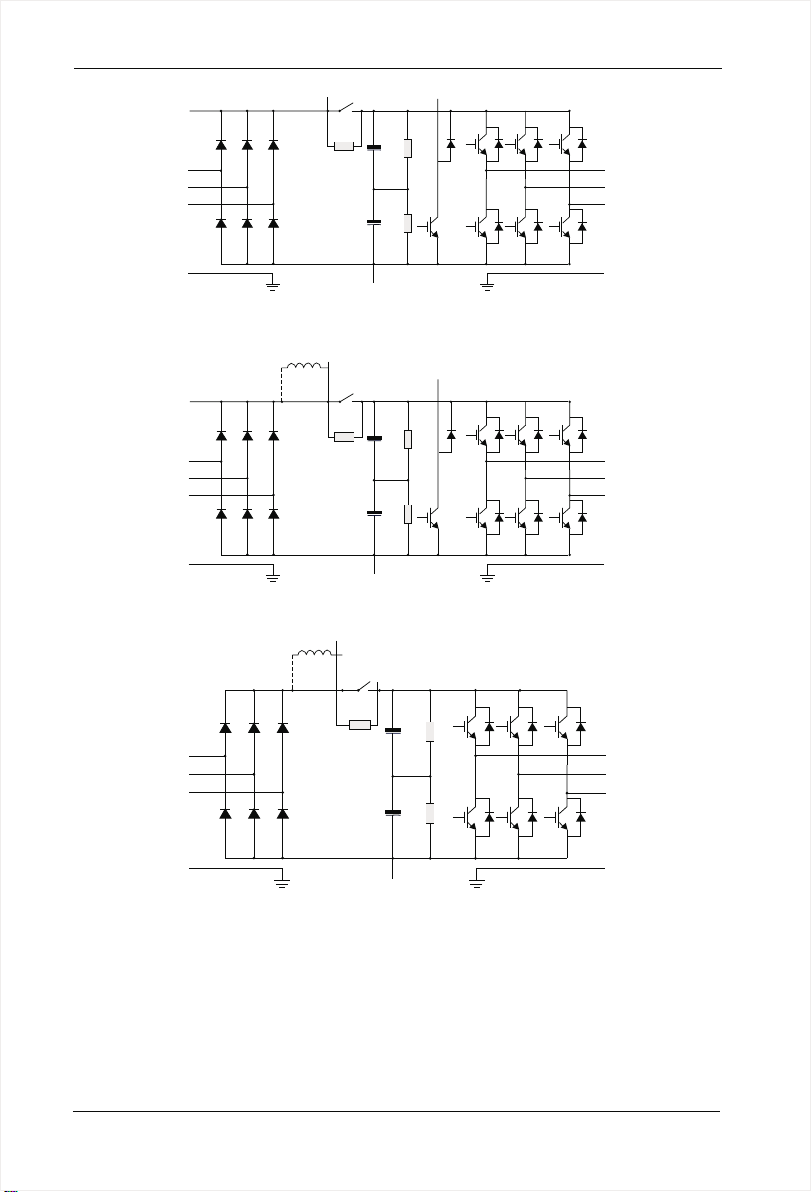
The following figure shows the AC drive main circuit diagram. Rectifie make three-phase
AC voltage into DC voltage. Capacitor groups of intermediate circuit stabilize the DC
voltage .The AC drive converts of the DC voltage to AC voltage for AC motor use. When
the voltage in the circuit exceeds the maximum limit, the braking pipe will connect an
external braking resistor to the intermediate DC circuit to consume the feedback energy.
-1 5-
Page 16
Chapter 2 Product Information
SD200 User Manual
R
S
T
PE
P+
P-
PB
Figure 2-1 Main Circuit Diagram( less than 18.5 kw (including))
DC reactor
R
S
T
PE
P+
P
P-
PB
Figure 2-2 Main Circuit Diagram (22kw~30kw)
DC reactor
P+
U
V
W
PE
U
V
W
PE
P
R
S
T
PE
P-
U
V
W
PE
Figure 2-3 Main Circuit Diagram (over 30kw)
Note:
Higher than 22kw AC drive (including) support for external DC reactor, before
1.
connecting, it need to take down the bronze between P and P +. 1.
2. Lower than 30kw AC drive (including) support for external braking resistor, higher than
37kw AC drive (including) support for external braking unit , braking resistor.
-1 6-
Page 17
SD200 User Manual
Chapter 2 Product Information
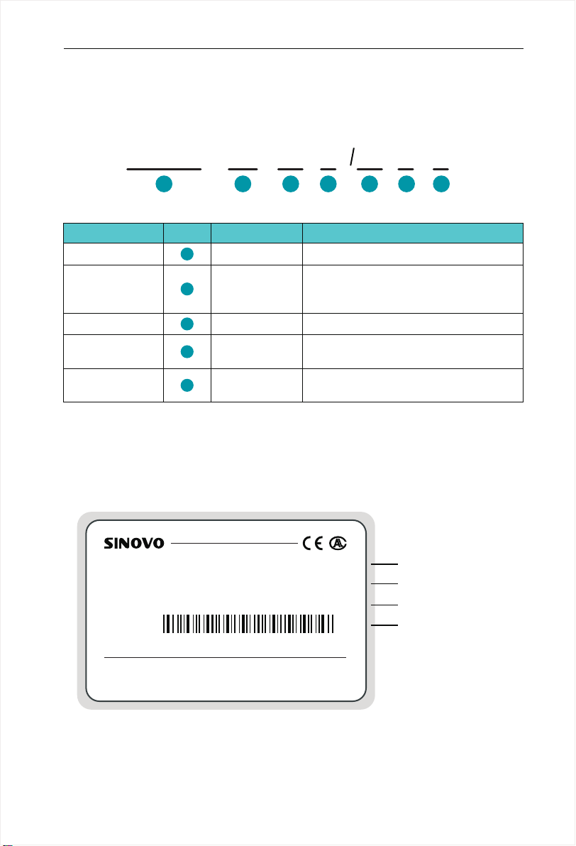
2.3 Naming Rules
In the model code contains the product information Users can find the code from the
transducerand simple nameplate.
SD200
Field Mark
Ac drive series
Voltage Level
Adaptive Power
Function Type
braking Unit
1
1
2
3
4
5
4T
-
2 4
Explanation
Ac drive series
Voltage Level
Adaptive Power
Function Type
braking Unit
Figure 2-4 Name Designation Rules
2.4 Nameplate
MODEL: SD200-4T-5.5 G/ 7. 5P C
INPUT: AC3PH 380V 50/60Hz 14. 6A /2 0. 5A
OUTPUT: AC3PH 380V 0 600Hz 13A/17A~
S/N: FDLAGCA0A040
11
-
3 3
G
15
P
C
4
Content
Sinodrive200 abbreviated SD200
2S:single-phase 220V
2T:Three-phase 220V
4T:Three-phase 380V
0.7KW~500KW
G:General
P:Fan pump
NullC::None
Only braking unit
Model of the AC drive
Rated input voltage,
frequency and current
Rated output voltage,
frequency and current
Bar code
5
SHENZHEN SINOVO ELECTRIC TECHNOLOGIES CO.,LTD.
Figure 2-4 Name Designation Rules
MADE IN C HINA
-1 7-
Page 18
Chapter 2 Product Information
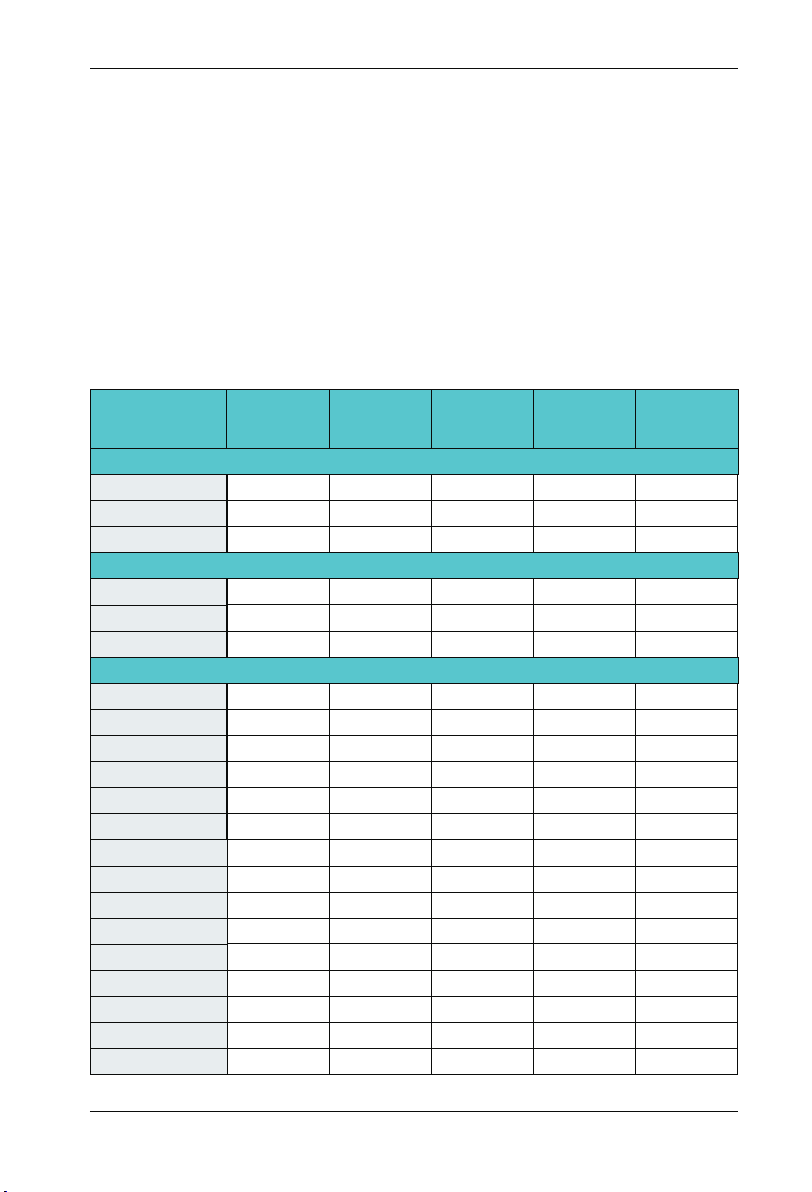
2.5 SD200 Series of AC drive
SD200 User Manual
Model
SD200-2S-0.7G
SD200- -1.52S G
SD200- -2.22S G
SD200-2T-0.7G
SD200- -1.52T G
SD200- -2.22T G
SD200-4T-0.7G
SD200-4T-1.5G
SD200-4T-2.2G
SD200-4T-4.0G
SD200-4T-5.5G
SD200-4T-7.5G
SD200-4T-11G
SD200-4T-15G
SD200-4T-18.5G
SD200-4T-22G
SD200-4T-30G
SD200-4T-37G
SD200-4T-45G
SD200-4T-55G
SD200-4T-75G
SD200-4T-90G
SD200-4T-110G
SD200-4T-132G
SD200-4T-160G
SD200-4T-185G
SD200-4T-200G
SD200-4T-220G
SD200-4T-250G
SD200-4T-280G
SD200-4T-315G
Power Capacity
(KVA)
Single-phase 220V Range:-15%~20%
1.5
3.0
4.0
Three-phase 220V Range:-15%~20%
1.5
3.0
4.0
Three-phase 380V Range:-15%~20%
1.5
3.0
4.0
5.9
8.9
11
17
21
24
30
40
57
69
85
114
134
160
192
231
255
287
311
355
396
439
Input Current
(A)
8.2 0.754.7 0.75
14.0 7.5
23.0
5.5 0.754.7 0.75
7.7 7.5
12.0
3.4 0.752.3 0.75
5.0 3.7
5.8
10.5 8.5 4.0
14.6 13
20.5
26.0 25 11
35.0 32
38.5 37 18.5
46.5 45
62.5 60 30
76.0
92.0 91 45
113
157
180 176 90
214
256 253 132
307 304 160
333 330 185
380 377 200
429 426 220
470 465 250
525 520 280
605 600 315
Output Current
Adaptable Motor
(A)
10.0
10.0
5.1
17 7.5
75
112
150
210 110
(KW)
1.5
2.2
1.5
2.2
1.5
2.2
5.5
15
22
37
55
75
-1 8-
Page 19
SD200 User Manual
Chapter 2 Product Information
Model
SD200-4T-400G
SD200-4T-450G
SD200-4T-500G
Power Capacity
(KVA)
479
530
600
660
Input Current
(A)
Output Current
(A)
665 660 350SD200-4T-350G
730 725 400
825 820 450
910 900 500
Adaptable Motor
(KW)
Note:
1. 0.75 ~ 315 kw AC drive input current is the measured results, which under the condition
of input voltage 380V, and without DC reactor as well as input and output reactor;
2. 350 ~ 500 kw AC drive input current is the measured results, which under the condition
of input voltage 380V, and equipped with input reactor;
3. Rated output current is defined as the output current of the output voltage 380V.
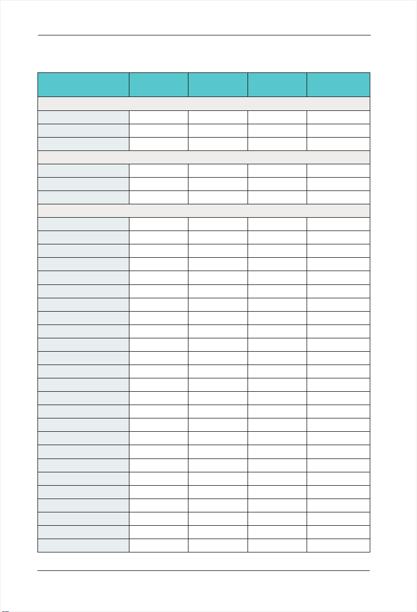
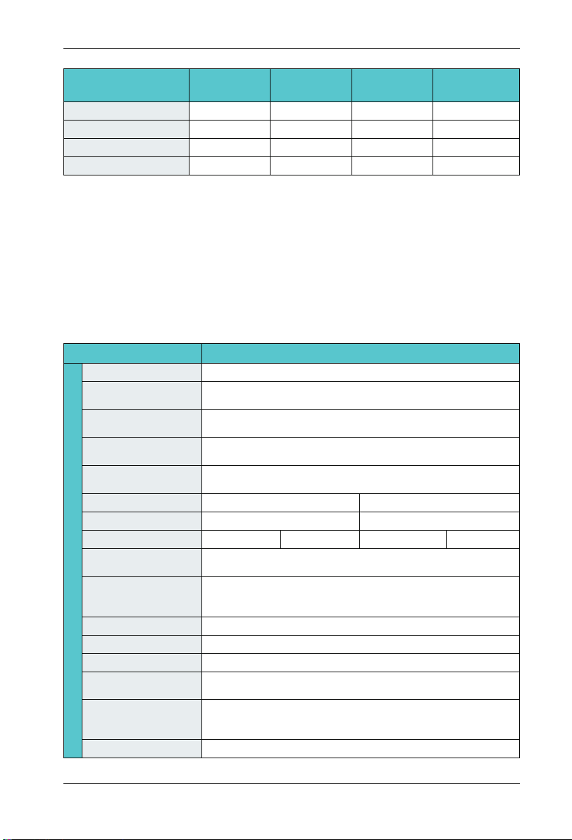
2.6 Technical Specifications
Item
Maximum frequency
Carrier frequency
Input frequency
resolution
Control mode
Speed range
Overload capacity
Basic Function
Torque boost
V/F curve
Accelerate/
Decelerate curve
DC braking
Jog control
Simple PLC Multi-speed
Onboard PID
Auto voltage
regulation (AVR)
Overvoltage/overcurrent
stall control
Rapid current limit
0~600Hz
2.0kHz~16.0kHz; The carrier frequency is automatically adjusted
based on the load features.
Digital setting: 0.01Hz
Analog setting : Maximum frequency x 0.025%
0:V/F control
1:Vector control 0 mode
1:50(vector control 0 mode)
G type:150% rated current for 60s
Line or S-curve Acc/Dec mode, four kinds of Acc/Dec time Range of
Acc/Dec time 0.0~6000.0s
DC braking frequency : 0.00Hz to Maximum frequency
braking time: 0.0 to 100.0s
braking current : 0.0 to 150%
Jog frequency range: 0.00Hz~F00.03Maximum frequency
16-speed operating through built-in PLC or control terminal
It realizes process-controlled closed loop control system easily.
Jog frequency range: 0.00Hz~Maximum frequency
The current and voltage are limited automatically during
the running process so as to avoid frequent tripping due to
overvoltage/overcurrent.
It helps to avoid frequent over- current faults of the AC drive.
Specification
Auto torque boost
Line
Multi-point
P type: 110% rated current for 60s
Manual torque boost: 0.1%~20.0%
Square V/F curve
VF separation
-1 9-
Page 20

Chapter 2 Product Information
SD200 User Manual
Non stop function
Speed tracking start
Freatures
Rapid current limit
Timing Control
Multi-motor switch
Bus Support
Motor overheating
protection
Command source
Frequency source
Auxiliary frequency
source
Running
Input terminal
Output terminal
LED display
The key lock and
Display and
function selection
operation
Protection function
Protection function
Accessories
Item
Virtual IO
Specification
Load feedback energy compensates the voltage reduction so that
the AC drive can continue to run in a short time in case of power
interruption.
Identify the speed of rapidly rotating motor to realize a smooth start
without any rush.
Rapid software and hardware current limiting technology helps to
avoid frequent over-current fault.
Four sets of virtual DO, five groups of virtual DI, enables easy logic
control.
Timing control: set the time range 0.0Min~6500.0Min
Two independent motor parameters enable two motors switching
control
Two independent Modbus communication, profibus-DP
Optional IO expansion card 1, analog input AI5 acceptable the input
of motor temperature sensor .(PT100,PT1000)
Given the control panel, control terminal, serial communication port
given. It can be switched by a variety of ways.
12 frequency sources: digital setting, analog voltage setting, analog
current setting, pulse setting and serial port. It can be switched by a
variety of ways.
12 auxiliary frequency source. Flexible implementation of auxiliary
frequency tuning, frequency synthesis.
Standard:
. Six digital input terminals, one of which support to 50kHz high speed pulse input
. Three analog input terminals, two of which supports -10V~10V
voltage input
. One support 0 ~ 10V voltage input or 0 ~ 20mA current input
Expansion capability:
. Two digital inputs
. One analog input terminal, support 0-10.00V 0-20mA input, and
( )
supports PT100 / Pt1000
Standard:
. One high-speed pulse output terminal (optional open collector
type), support of 0 ~ 50kHz square wave signal output
. One digital output terminal
. Two relay output terminals
. Two analog output terminals, support 0~20mA current output or
0~10V voltage output
Display each parameter of function code group
Achieve some or all of the keys locked and define the scope of
partial keys to prevent misuse.
Powered motor short circuit test; Input/output phase failure protec
tion; Over current protection; voltage protection; Under voltage pr
otection; Over heat protection ; Overload protection; braking resis
tor fault protection.
Brake unit, Simple IO expansion card, Multi-functional IO expansion
card
-
-
-
-2 0-
Page 21

SD200 User Manual
Chapter 2 Product Information
Item
Application environment
Environment
Altitude
Ambient temperature
Humidity
Vibration
Storage temperature
Specification
In-door, free from direct sunlight, dust, corrosive gas, combustible
ga , oil mist, steam , water drop and salt .
Lower than 1000m (1000m-3000m for derated use)
-10℃+40℃ (derated use in the ambient temperature of 40℃ to 50 ℃ )
Less than 95%RH, without condensation
Less than 5.9m/s(0.6g)
-20℃~+60℃
-2 1-
Page 22
Chapter 2 Product Information
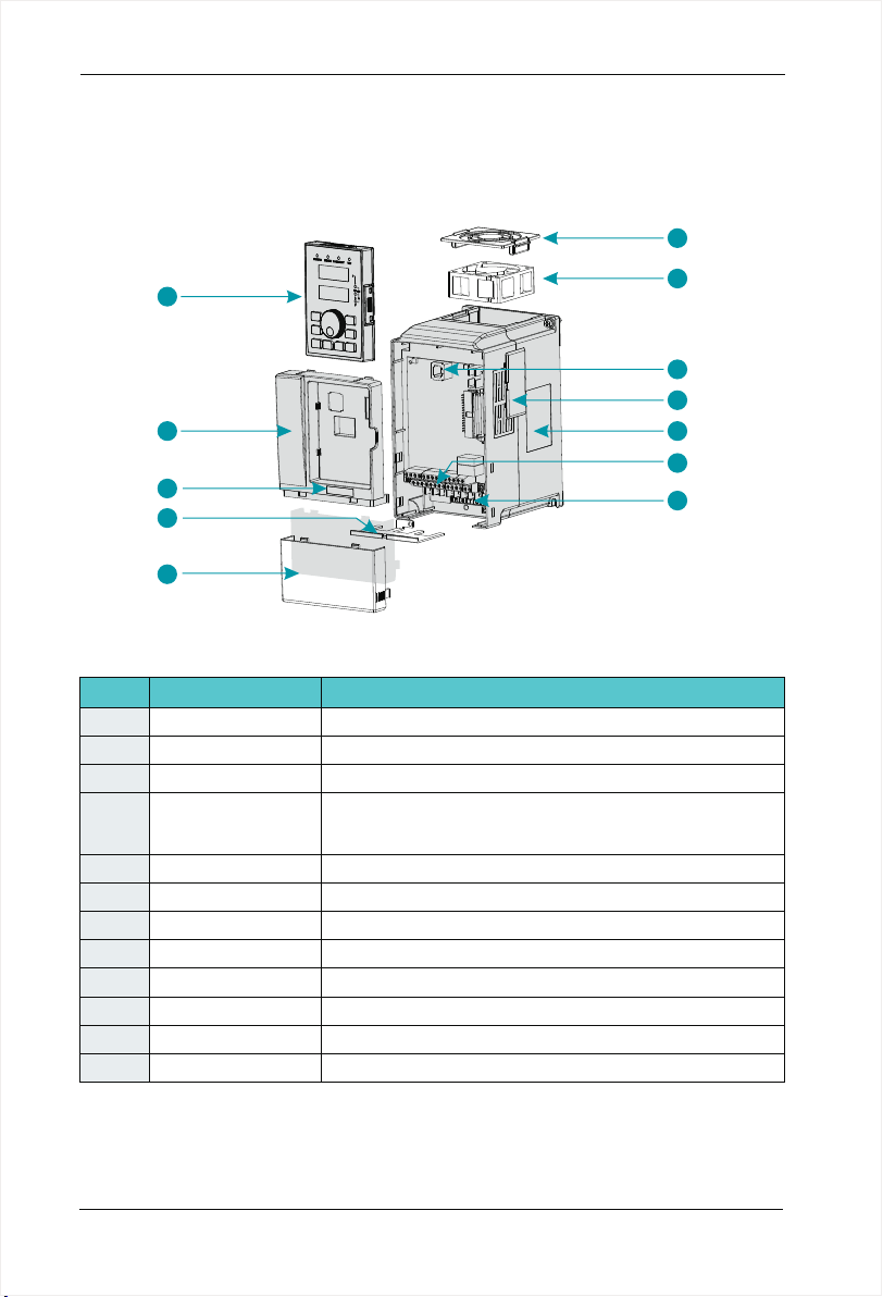
2.7 Structure diagram
2.7.1 The following figure shows the layout of the AC drive
( 2.2KW,for example).
SD200 User Manual
1
8
9
10
11
12
No
1
2
3
4
5
6
7
Main circuit terminals
8
9
10
11
12
Name
Fan-cover
Cooling fan
Keypad interface
Vents-cover
Nameplate
Control terminals
Keypad
Cabinet-cover
Series Label
Apron
Lower-cover
Figure 2-6 Product structure diagram
Description
Protection fan.
Refer to 8.1 " Definition of Related Terms."
It is used to connect the Keypad.
Optional. with the vents-cover installed, the protection level will
increase and the AC drive internal temperature will increase as
well so please derating use the AC drive.
Refer to 2.4 "Nameplate"
Refer to 3.3 "Standard Wiring."
."
Refer to 3.3 "Standard Wiring."
Refer to chapter4 "Operation, Display and Application Examples."
Protect the internal components.
Refer to 2.3 "Naming Rules".
Convenient input and output wiring.
Protect the internal components.
2
3
4
5
6
7
-2 2-
Page 23
SD200 User Manual
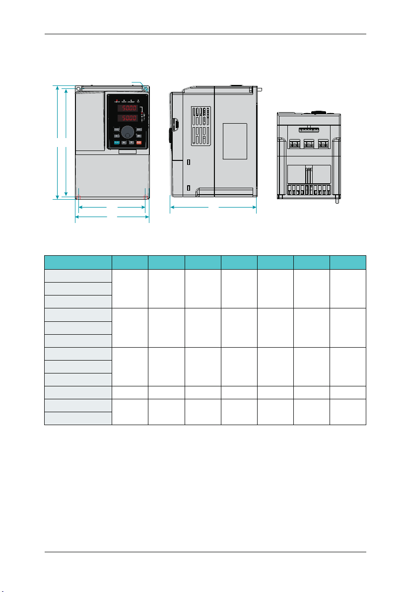
2.7.2 Product Outline, Installation Hole Size
2.7.2.1 SD200 series less than7.5KW (including 7.5KW)
Ø
H
H1
Chapter 2 Product Information
W1
W
D
Figure 2-7 Less than 7.5 KW AC drive installation dimensions and installation size
AC drive model
H(mm) W(mm) D(mm)
H1(mm) W1(mm)
D
SD200-2S-0.7G
SD200-2 -1.5S G
190 110 150 178 98
SD200-2 -2.2S G
SD200-2T-0.7G
SD200-2T-1.5G
190 110 150 178 98
SD200-2T-2.2G
SD200-4T-0.7G
SD200-4T-1.5G
190 110 150 178 98
SD200-4T-2.2G
SD200-4T-4.0G
SD200-4T-5.5G
SD200-4T-7.5G
210 130 160 198 118
250
155
176 236
141
iameter
(mm)
Ø5
Ø5
Ø5
Ø5
Ø5
GW(kg)
2.4
2.4
2.4
3.5
4.5
-2 3-
Page 24

Chapter 2 Product Information
2.7.2.2 SD200 Series 11KW~45KW
SD200 User Manual
H
W1
W
Figure 2-8 11kw~45kw AC drive installation dimensions and installation size
AC drive model
SD200-4T-11G
SD200-4T-15G
SD200-4T-18.5G
SD200-4T-22G
SD200-4T-30G
SD200-4T-37G
SD200-4T-45G
H(mm) W(mm) D(mm)
285
332
387
170 162 270
220
250 220 373
270 252 426 22.5440
2.7.2.3 SD200 Series 55KW~110KW
H
H1
D
D
H1(mm) W1(mm)
214
318
135
140
150
iameter
(mm)
Ø6
Ø7
GW(kg)
6.5
10.3
13
15
180
H1
Fig 2-9 55~110KW AC drive installation dimensions and installation size
AC drive model
SD200-4T-5 G5
SD200-4T-75G
SD200-4T-90G
SD200-4T-110G
W1
W
H(mm) W(mm) D(mm)
550
650
300 258 534 200
370 282 625 250
-2 4-
D
H1(mm) W1(mm)
iameter
D
(mm)
Ø9
GW(kg)
35.6
53
54
55
Page 25
SD200 User Manual
2.7.2.4 SD200 Series 132KW~185KW
H
H1
Chapter 2 Product Information
W1
W
D
Figure 2-10 132KW~185KW AC drive installation dimensions and installation size
AC drive model
H(mm) W(mm) D(mm)
H1(mm) W1(mm)
SD200-4T-132G
880 485 31 0 860 320
SD200-4T-185G
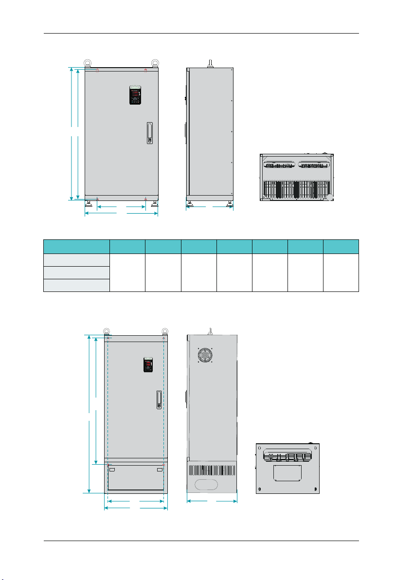
2.7.2.5 SD200 Series 200KW~500KW
H1
H
D
iameter
(mm)
Ø13
GW(kg)
99SD200-4T-160G
W1
W
D
Figure 2-11 200KW~500KW AC drive installation dimensions and installation size
-2 5-
Page 26
Chapter 2 Product Information
AC drive model
H(mm) W(mm) D(mm)
H1(mm) W1(mm)
SD200-4T-200G
SD200-4T-220G
1250 500 400 1000 440
SD200-4T-250G
SD200-4T-280G
SD200-4T-315G
1350 650 400 1105 513
SD200-4T-350G
SD200-4T-400G
SD200-4T-450G
1810 850 405 1410 513
SD200-4T-500G
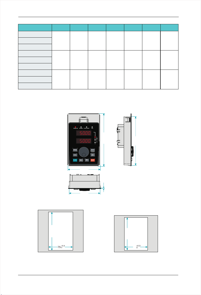
2.7.3 External Keypad Installation Dimensions
SD200 User Manual
iameter
D
(mm)
Ø13
Ø13
Ø13
GW(kg)
167
206
415
79.00
74.80
Figure 2-12 Keypad Installation dimensions
+0. 3
0
119. 5
Figure 2-13
Opening dimension diagram
for keypad with base
-2 6-
128.20
1.50
+0. 3
0
100
70
Figure 2-14
Opening dimension diagram
for keypad without base
119.00
Page 27
SD200 User Manual
Chapter 2 Product Information
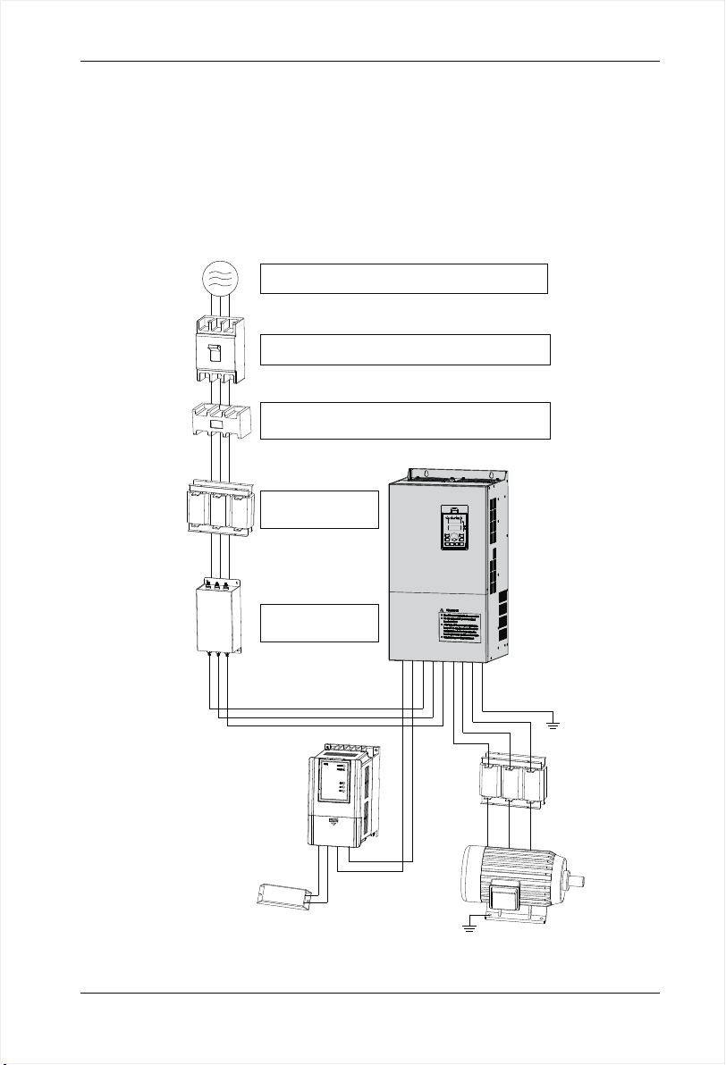
2.8 Peripheral Electrical Components System Structure
When using SD200 series AC drive to control asynchronous motor system, you have to
install various electrical components on the side of input and output of the AC drive to
guarantee the stability and safety of system.In addition, SD200 series AC drive is equipped
with a variety of optional accessories and expansion card to achieve various functions.
More than 37kw series three-phase 380v system structure as shown in the figure
below(The figure AC drive terminal refer to 55~110KW):
3-phase AC
power supply
Moulded case
circuit breakeror
earth leakage
circuit breakers
Electromagnetic
contactor
AC reactor
Input side EMC
filter
Use within the allowable power supply specification
of the AC drive
Select a proper breaker to resistlarge in-rush current
that flows into the AC drive at power-on
To guarantee safety, use an electromagnetic contactor.
Do not use it to start or stop the AC drive because such
operation reduces the service life of the AC drive
Suppress the high
order harmonic to
improve power factor
AC Driver
Reduce the electrom
agnetic interference
on the input side.
Break unit
-
P
P+
R
P-
S
T
U
V
W
PE
Ground
Output reactors
PB
P
P+
Braking resistor
BR
P+
P-
Ground
Motor
Figure 2-15 Under 37 kw series 3-phase 380 V system structure diagram
-2 7-
Page 28

Chapter 2 Product Information
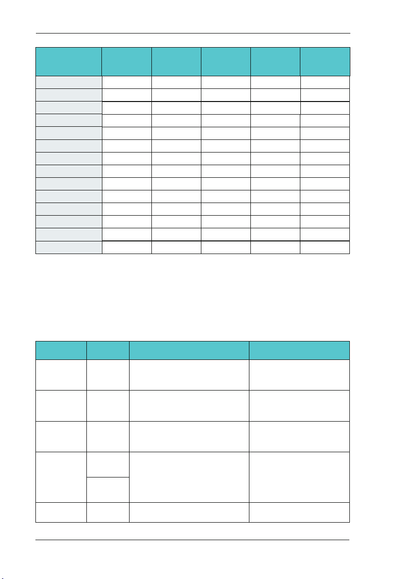
2.8.1 Peripheral Electrical Components Description
SD200 User Manual
Accessory
Name
MCCB
Contactor
AC input
reactor
EMC input
filter
DC reactor
AC output
reactor
Installation
position
Power
receiving side
Between MCCB
and the AC drive
input side
AC drive
input side
AC drive
input side
S 200 series
D
AC drive of
200G and above
configured
with DC reactor
as standard
Between the AC
drive output side
and the motor,
close to the AC
drive
Function Description
Interrupt the power supply when overcurrent occurs on
ª
downstream devices.
Start and stop the AC drive.Do not start and stop the AC
ª
drive frequently by switching the contactor on and off (less
than twice per minute) nor use it to directly start the AC
drive.
Improve the power factor of the input side;
ª
Eliminate the higher harmonics of the input side effecti-vely
ª
and prevent other devices from being damaged due
to distortion of the voltage waveform;
ª
Eliminate the input current unbalance due to unbalance
ª
between the power phases;
Reduce the external conduction and radiation interfere-
ª
nce of the AC drive;
ª
Decrease the conduction interference flowing from the
ª
power end to the AC drive and improve the anti-interfe-
ª
rence capacity of the AC drive.
ª
Improve the input power factor;
ª
Improve the efficiency and thermal stability of the AC drive;
ª
Eliminate the impact of higher harmonics of the AC drive
ª
input side and reduce the external conduction and
radiation interference.
The output side of the AC drive generally has much higher
ª
harmonics. When the motor is far from the AC drive, there
is much distributed capacitance in the circuit and certain
harmonics may cause resonance in the circuit, bringing
about the following two impacts:
a.Degrade the motor insulation performance and damage
ª
the motor in the long run.
b.Generate large leakage current and cause frequent AC
ª
drive protection trips.
If the distance between the AC drive and the motor is
ª
greater than 100 m, install an AC output reactor.
-2 8-
Page 29
SD200 User Manual
Chapter 2 Product Information
Note:
Do not install capacitor or surge suppressor on the output side of the AC drive. Otherwise, it
1.
may cause faults to the AC drive or damage to the capacitor and surge suppressor;
2. Input/output (main circuit) of the AC drive include harmonic components, which may interfere
with the AC drive attachment communications equipment. Therefore, install an anti-aliasing filter
to minimize the interference;
3. Details of peripherals and options refer to Chapter 2 selection of peripheral devices.
2.8.2 Peripheral electrical components selection guidance
AC Drive model
SD200-2S-0.7G
SD200-2 -1.5S G
SD200-2 -2.2S G
SD200-2T-0.7G
SD200-2T-1.5G
SD200-2T-2.2G
SD200-4T-0.7G
SD200-4T-1.5G
SD200-4T-2.2G
SD200-4T-4.0G
SD200-4T-5.5G
SD200-4T-7.5G
SD200-4T-11G
SD200-4T-15G
SD200-4T-18.5G
SD200-4T-22G
SD200-4T-30G
SD200-4T-37G
SD200-4T-45G
SD200-4T-5 G5
SD200-4T-75G
MCCB(A)
100
100
125
160
200
250
210
Recommended
contactor
Single phase 220V
16
20
32
16
25
25
10
16
16
25 16 4.0 4.0 1.0
32 25 4.0 4.0 1.0
40 30 4.0 6.0 1.0
63
63
10
16
20
Three phase 220V
10
16
16
380VThree phase
6
10
10
40
40
63
63
100
100
125
160
160
Recommended
input side main
circuit wire mm2
2.5
4.0
6.0
2.5
4.0
4.0
2.5
2.5
2.5
4.0
6.0
10
16
16
25
50
60
6
Recommended
output side main
circuit wire mm2
2.5
2.5
4.0
2.5
2.5
4.0
2.5
2.5
2.5
6.0
10
10
10
16
25
25
35
50
Recommended
control loop
wire mm2
1.0
1.0
1.0
1.0
1.0
1.0
1.0
1.0
1.0
1.0
1.0
1.5
1.5
1.5
1.5
1.5
1.5
1.5
-2 9-
Page 30
Chapter 2 Product Information
SD200 User Manual
AC Drive model
SD200-4T-90G
SD200-4T-110G
SD200-4T-132G
SD200-4T-160G
SD200-4T-185G
SD200-4T-200G
SD200-4T-220G
SD200-4T-250G
SD200-4T-280G
SD200-4T-315G
SD200-4T-350G
SD200-4T-400G
SD200-4T-450G
SD200-4T-500G
MCCB(A)
250
350
400
500
600
600
600
800
800 800 185*2 185*2
1000 800 150*3 150*3
1000 800 150*4 150*4
1200
1200
1600
Recommended
contactor
160
350
400
400
400
600
600
600
1000
1000
1000
Recommended
input side main
circuit wire mm2
70
120
150
185
185
150*2
150*2
185*2
150*4
150*4
150*4
Recommended
output side main
circuit wire mm2
50
120
150
185
185
150*2
150*2
185*2
150*4
150*4
150*4
Recommended
control loop
wire mm2
1.5
1.5
1.5
1.5
1.5
1.5
1.5
1.5
1.5
1.5
1.5
1.5
1.5
1.5
2.9 SD200 Optional Parts
Peripheral optional braking unit, each function expansion card and the outer lead operator,
etc..As shown below. Seeing detailed usage instructions for use of the accessory. For the
following options, please note when ordering.
Internal
braking unit
External
braking unit
Multi-function
I/O expansion
card
Modbus
communication
card
Profibus-DP
card
Type
Models
followed
by letter "C”
SDBUN
SDIO
SDRS485
SDCAN
SDDP
Function
Models power under 22KW are
installed with the internal braking
unit as standard configuration
37KW and above need to be
configured with an external
braking unit
Increase 3 digital inputs, 2 digital
outputs, two relay outputs, two
analog voltage input T_Motor
One RS - 485 communication
card, one CAN communication
card.
Profibus-DP card DB9interface,
-3 0-
RemarkName
For 30KW model power,
the braking unit is optional
Multiple braking ones are
connected in parallel for
the models above 90KW
It applies to all models
It applies to all models
It applies to all models
Page 31

SD200 User Manual
Chapter 2 Product Information
2.9.1 Selection Braking Unit
The section recommend braking assembly is instructional data, user can select different
resistance value and power according to actual situation. (Resistance values can not be
lower than the recommended ones , the power can be higher than recommended ones).
Braking rem inertia, deceleration time, energy of potential energy load. Customs select the
AC drive should comply esistance can be selected according to the power of motor in
actual applied system. They are also related to systwith the actual situation. The bigger of
the system inertia, the shorter of the deceleration time, the more frequent of the braking,
and the braking resistence should select larger power and smaller resistance .
2.9.1.1 The Selection of Resistance Value
When braking, almost all renewable energy consumption of the motor is on the braking
resistor,According to the formula:
ª U*U/R=Pb
ª U------ Braking voltage at stable braking system.
(System selections differs in braking voltages, The AC380Vsystem usually selects
DC700V braking voltage.)
ª Pb-----Braking power
2.9.1.2 The Selection of braking Resistor Power
Elevator---20%~30% Open and draw volume---20%~30%
Centrifuge---50%~60% Accidental braking load---5%
Commonly take 10%
2.9.1.3 Selection of Reference
When the AC drive is driven by the control device requiring rapid braking, the braking unit
needs to release the power of the motor braking feedback to the DC bus. 400V voltage
level 0.4 ~30kw is equipped with built-in braking unit, if you need to rapid stop, please refer
to the appropriate braking to select the unit and braking resistance, AC drive capacity, if
need to stop, it can be directly connected to the braking resistance. Please choose the
appropriate braking unit according to the braking resistance of the AC drive capacity.
-3 1-
Page 32

Chapter 2 Product Information
SD200 User Manual
AC drive
Capacity
(kw)
0.75
1.5
2.2
4.0
5.5
7.5
11
15
18.5
22
30
37
45
55
75
90
110
132
160
185
200
220
Braking Unit
Specification
Built-in as
standard
Built-in
Optional
EHBU70
Quantity
1
1
1
1
1
1
1
1
1
1
1
1
1
1
1
2
2
2
3
3
4
4
4
Resistance
≥300Ω0.4
≥300Ω
≥220Ω
≥200Ω
≥130Ω
≥90Ω
≥65Ω
≥40Ω
≥32Ω
≥25Ω
≥22Ω
≥16Ω
≥16Ω
≥16Ω
≥8Ω
≥8Ω
≥8Ω
≥8Ω
≥8Ω
≥8Ω
≥8Ω
≥8Ω
≥8Ω
Braking Resistor
Power
150W
150W
150W
250W
300W
400W
500W
800W
1000W
1300W
1500W
2500W
3700W
4500W
5500W
3700W
4500W
5500W
3700W
5500W
4500W
5500W
5500W
Quantity
1
1
1
1
1
1
1
1
1
1
1
1
1
1
1
2
2
2
3
3
4
4
4
2.10 Connection Methods
2.10.1 Braking Resistor Connection
SD200 series AC drive braking resistor connection as shown in figure 2-16.
P+
-3 2-
Braking
resistor
AC Driver
PB
Figure 2-16 braking resistor connection
Page 33

SD200 User Manual
Chapter 2 Product Information
2.10.2 Braking Unit Connection
SD200 series AC drive and the braking unit connection as shown in figure 2 -17.
P+
AC Driver
P-
Figure 2-17 braking unit connection
B1
+
braking
unit
B2
-
Braking
resistor
2.10.3 Braking ones in Parallel Connection
When a single braking unit failing to meet the needs of the braking energy, two or more
braking ones are required in parallel connection, as shown in figure 2-18.
P+
AC Driver
P-
B1
+
braking
unit
B2
-
Braking
resistor
B1
+
braking
unit
B2
-
Figure 2-18 braking ones in parallel connection
Braking
resistor
-3 3-
Page 34

-3 4-
Page 35

Chapter 3
Mechanical and Electrical Installation
3.1 Chapter of This Content
This chapter introduce the mechanical and electrical installation of the AC drive.
Danger
Only those who are trained and qualified professionals can operate the work described in
ª
this chapter. Please operate according to the section of "pay attention to security
matters", failure to these may cause personal injury or damage to equipment.
Power supply of AC drive must be disconnected before the installation. If the AC drive has
ª
connected to power, please power off first and then wait not less than the time marked on
the AC drive and confirm the Charge Lamp was already off, users in such condition are
advised to use the multimeter to measure if the DC bus voltage of the AC drive is under
36v.
The installation and design of the AC drive must comply with relevant laws and regulations
ª
of the installation region. If the installation of the AC drive violates the requirements of
local laws and regulations, We Our company does not assume any legal responsibility. In
addition, if user are not comply with the recommendations, the AC drive may appear
some faults not covered by the warranty.
-3 5-
Page 36

Chapter 3 Mechanical and Electrical Installation
SD200 User Manual
3.2 Mechanical Installation
3.2.1 Installation Environment
In order to make full use of the performance of the AC drive and maintain its function for a long
time, it is very important to install the environment. Please install the AC drive in the following
table of the described environment.
Environment
Installation site Indoor
-10~+50℃.
ª
If the ambient temperature of the AC drive is above 40℃, derate 3% for
ª
every additional 1℃.
It is not recommended to use the AC drive if the ambient temperature is
ª
above 50℃.
In order to improve the reliability of the device, do not use the inverter if
ª
Ambient
temperature
Humidity
Storage
temperature
Running
Environment
Condition
the ambient temperature changes frequently.
Please provide cooling fan or air conditioner to control the internal
ª
ambient temperature below the required one if the AC drive is used in a
close space such as in the control cabinet.
When the temperature is too low, if the AC drive needs to restart to run
ª
after a long stop, it is necessary to provide an external heating device
to increase the internal temperature, otherwise damage to the devices
may occur.
Rh≤90%
ª
No condensation is allowed, The maximum relative humidity should be
ª
equal to or less than 60% in corrosive air.
- ℃30~+60
The installation site of the AC drive should:
ª
keep away from the electromagnetic radiation source;
ª
keep away from contaminative air, such as corrosive gas, oil mist and
ª
flammable gas;
ensure foreign objects,such as metal power,dust,oil,water can not enter
ª
into the AC drive(do not install the AC drive on the flammable materials
such as wood)
keep away from direct sunlight,oil mist,steam and vibration environment;
ª
Conditions
Altitude
Vibration
Installation
direction
<
1000m,If the sea level is above 100m,please derate 1% for every
additional 100m.
≤5.8m//s²(0.6g)
AC drive should be installed on an upright position to ensure sufficient
cooling effect.
-3 6-
Page 37

SD200 User Manual
Chapter 3 Mechanical and Electrical Installation
Note:
1.
SD200 series AC drive should be installed in a clean and ventilated environment accord-
ing to enclosure classification.
2. Cooling air must be clean,free from corrosive materials and electrically conductive dust.
3.2.2 Installation Direction
The AC drive may be installed on the wall or in a cabinet.
The AC drive must be installed in an upright position. Check the installation site according to
the requirements below.Refer to chapter 3.1 outline diagram for frame details.
OK
NG
NG
A. Vertical installation
B. Alinic installation
Figure 3-1 Installation direction of AC drive
C. Transverse installation
3.2.3 Installation Manner
Wall mounting(for the AC drive of 380V 315KW)≤
Figure3-2 Installation manner
Mark the hole location. The location of the holes is shown in the outline diagram in 3.2
1.
charpter;
2. Fix the screws or bolts to the marked locations;
3. Put the AC drive against the wall;
4. Tighten the screws in the wall securely.
-3 7-
Page 38

Chapter 3 Mechanical and Electrical Installation
3.2.4 Single Installation
SD200 User Manual
A
B B
A
Figure 3-3 Single installation
Warm Air
Cool Air
Note:
B min. 5MM; C: 30KW below min. 200MM, 37KW above min. 300MM.
3.2.5 Multiple Installation
A
Warm Air
C
C
C
B
A
D
Figure 3-4 Parallel installation
B
Cool Air
C
Note:
1. When installing ac drives with different sizes, align the upper positions of each ac drives
before installing them. This is easy to maintain on later stage.
2. B, D min. size is 5MM; C: 30kw below min. 200MM, 37KW above mini. 300MM
-3 8-
Page 39

SD200 User Manual
3.2.6 Vertical Installation
W
arm Air
Chapter 3 Mechanical and Electrical Installation
Wind Board
Cool
Air
Wind Board
Cool Air
Warm Air
Figure 3-5 Vertical installation
Note:
Windscreen should be installed in vertical installation for avoiding mutual impact and
insufficient cooling.
-3 9-
Page 40

Chapter 3 Mechanical and Electrical Installation
3.2.7 Canted Installation
Air
ol
o
C
SD200 User Manual
r
i
m A
ar
W
ir
A
m
r
a
W
r
Cool Ai
ir
A
m
r
a
W
r
i
Cool A
Figure 3-6 Tilt installation
Note:
Ensure the seperation of the wind input and output channels in tilt installation for avoiding
mutual impact..
-4 0-
Page 41

SD200 User Manual
Chapter 3 Mechanical and Electrical Installation
3.3 Standard Wiring
3.3.1 Main Circuit Wiring Diagram
MCCB
R
S
3-phase 380V
input power 50/60HZ
3-phase 380V
input power 50/60HZ
3-phase 380V
input power 50/60HZ
T
MCCB
R
S
T
MCCB
R
S
T
Figure 3-7 Ma in c ir cuit wiring diagr am
braking resistor
PB
R
S
T
R
S
T
DC re actor
R
S
T
P+ P -
18.5KW
(including)Below
P
PB
P+
22~30KW
braki ng resist or
braki ng unit
P
P+
37KW
(including)Above
DC re actor
P-
P-
PE
PE
PE
U
V
W
U
V
W
U
V
W
Note:
1. DC reactor, braking unit and braking resistor are optional accessories”.
M
M
M
2. P1 and(+) are short circuited in factory, if need to connect with the DC reactor, please
remove the contact tag between P1 and (+).
3.3.2 Main Circuit Terminals Diagram
P+ P- P B R S T U V WP P PB R S T U V W+ -
PEPE
Figure 3-8 7.5KW below main circuit terminal diagram
-4 1-
Page 42

Chapter 3 Mechanical and Electrical Installation
+ -
P+ P- PB R S T U V W
P P PB R S T U V W
P+ P- PB R S T U V W PEP P PB R S T U V W PE+ -
Figure 3-9 11~18.5kw main circuit terminal diagram
P P+ P- P B R S T U V W
P P P P B R S T U V W + -
PE
P P+ P- PB R S T U V W
P P P PB R S T U V W + -
PE
Figure 3-10 22kw main circuit terminal diagram
SD200 User Manual
PE
PE
PE
PE
R S T PB P P+ P- U V W
R S T PB P P P U V W PE+ -
R S T P P+ P- U V W
R S T P P P U V W + -
POWER (电源)
POWER ( )电源
MOTOR (电机)
MOTOR ( )电机
R S T PB P P+ P - U V W R S T PB P P P U V W + -
PE
Figure 3-11 30kw main circuit terminal diagram
R S T P P+ P- U V W
R S T P P P U V W + -
PO WE R (电源)
PO WE R ( )电源
PE
PE
Figure 3-12 37~45kw main circuit terminal diagram
-4 2-
MO TO R (电机)MO TO R ( )电机
PEP E
PEPE
Page 43

SD200 User Manual
P P+ P- R S T U V W
P P P R S T U V W + -
POWER (电源)
POWER ( )电源
P+
P+
P-
P-
S
S
T
T
P
P
R
R
Chapter 3 Mechanical and Electrical Installation
P P+ P - R S T U V W
P P P R S T U V W + -
PE
PE
MOTOR (电机)
MOTOR ( )电机
Figure 3-13 55~110kw main circuit terminal diagram
S
S
T
R
R
U
U
PE
PE
W
W
V
V
Figure 3-14 380V 132~185kw main circuit terminal diagram
T
POW ER
POW ER
P+
P+
P-
P
P
P-
U
U
MOT ORM OTO R
V
V
PEP E
PE
PE
W
W
Figure 3-15 380V 200~500kw main circuit terminal diagram
-4 3-
Page 44

Chapter 3 Mechanical and Electrical Installation
Terminal Name
Terminal
18.5KW
(including)
22~33KW
below
R、S、T
U、V、W
P
P+
P-
PB
PE
Braking resistor
Braking resistor
Power input of the main circuit
AC drive output
Without the
terminal
terminal
/
terminal
400V:Grounding resistance is less than 10Ω
DC reactor
terminal
DC reactor
terminal braking resistor
terminal
/
Braking resistor
terminal
37KW
(including)
above
DC reactor
terminal
DC reactor
terminal
braking unit
terminal
Braking unit
terminal
Without the
terminal
SD200 User Manual
Function Description
3-phase AC input terminals
which are generally connected with the power supply.
Three-phase AC output terminals, general connected to
the motor.
P、P1 and (+) are connected
with the terminals of DC
reactor.
P(+) and P(-) are connected
with the terminals of braking
unit.
PB and P(+) are connected
with the terminals of braking
resistor.
Protective grounding terminals, every machine is provided 2 PE terminals as the
standard configuration.These
terminals should be grounded
with proper techniques.
Note:
1. Do not use an asymmetrically constructed motor cable. If there is a sysmmetically
constructed grounding conductor in the motor cable in addition to the conductive shield,connect
the grounding conductor to the grounding terminal at the AC drive and motor ends;
2. Braking resistor, braking unit and DC reactor are optional parts;
3. Route the motor cable,input power cable and control cables seperately;
4. If the terminal description is"/",the machine does not provide the terminal as the external
terminal.
-4 4-
Page 45

SD200 User Manual
Chapter 3 Mechanical and Electrical Installation
3.3.3 Main Circuit Terminal Wiring Process
1. Fasten the grounding conductor of the input power cable with the grounding terminal of the
AC drive(PE)by 360 degree grounding technique. Connect the phase conductors to R, S, and T
terminals and fasten;
2. Strip the motor cable and connect the shield to the grounding terminal of the AC drive by 360
degree grounding technique. Connect the phase conductors to U, V and W terminals and
fasten;
3. Connect the optional brake resistor with a shielded cable to the designated position by the
same procedures in the previous step;
4. Secure the cables outside the AC drive mechanically.
NG Y
Screws are not fastened Screws are fastened
Figure 3-15 Screw installation diagram
OK
PE
Correct grounding method
Enclosure
Enclosure
NG
PE
Wrong grounding method
PE
Enclosure
Figure 3-16 360-degree grounding technique diagram
Enclosure
-4 5-
Page 46

Chapter 3 Mechanical and Electrical Installation
3.3.4 Control Circuit Wiring Diagram
SD200 User Manual
braking resistor
MCCB
R
S
T
3-phase380V/480V
Input power 50/60Hz
Digital input 1
Digital input 2
Digital input 3
Digital input 4
Digital input 5
High-speed pulse input
3
DC:0~10V/0~20mA
2
1kΩ 5kΩ~
1
DC:-10V~10V
DC:-10V~10V
P-
R
S
T
SD200
Main circuit
+24V
OPEN
DI1
DI2
DI3
DI4
DI5
HDI1
COM
Analog input
reference voltage
+10V
Analog input 1
AI1
AI2
AI3
GND
PE(connect cabinet )
J9
V
I
Analog input 2
Analog input 3
T
S
Control circuit
P+
PB
U
V
W
DISP1
J7
485
ON
OFF
A
B
A
B
J3
AO1
V
I
J4
AO2
V
I
GND
HDO1
CME
DO1
CME
T1C
T1B
T1A
T2C
T2A
M
Keypad interface
Expansion card interface
485 communication interface
Analog output AO 1,AO2
0V-10V/0mA 20mA-
Open collector output 1
( )
High-speed pulse output
Open collector output2
Relay output1
Relay output2
Figure 3-17 Wiring diagram of Control Circuit
Note:
This diagram is only suitable for the AC drive’s power rate below SD200-4T-18.5,for other
power rate refer to this chapter 3.3"Main Circuit Terminal Wiring".
-4 6-
Page 47

SD200 User Manual
3.3.5 Control Panel Terminals
Figure 3-18 Control terminal diagram
Control Panel Terminal Function Instructions
+10V
A
B AI1 GND
Chapter 3 Mechanical and Electrical Installation
AI2
AO1 AO2 HDI1 DI2 DI4 OPEN +24V COM
AI3
GND DI1
DI3 DI5
COM CME HDO1 DO1
T1A
T1B T1C
T2A T2C
Type
Analog
input
Digital
output
Terminal
+10V
Terminal name
Analog input
reference
Analog ground
Analog Input 1
AI1
Analog Input 2
AI2
Analog Input 3
AI3
Analog output 1
AO1
Analog output 2
AO2
Analog ground
+24V +24V
OPEN
Digital input
terminal common
voltage
Specification
10.5V(+3%)
Maximum output current 25mA/ the potentiometer
resistance range is more than 4KΩ.
Internal isolated with COMGND
0~20mA Input resistance 500Ω, max input current is 25mA:
0~10V Input resistance 100KΩ, max input voltage 12.5V:
Input range: 0–10VDC/0–20 mA, switched by jumper J9 on
the control board and factory defaulted as voltage input.
- Ω10V~10V Input resistance 25K:
Max. input voltage range:-12.5V~+12.5V
- Ω10V~10V: Input resistance 25K
Max input voltage range: -12.5V~+12.5V
0~20mA:Input resistance 200Ω~ Ω500
0~10V Ω: Input resistance >10K
Input range: 0–10 VDC/4–20 mA, switched by jumper J3 on
the control board and factory defaulted as voltage input.
0~20mA:Input resistance 200Ω~ Ω500
0~10V Ω: Input resistance >10K
Input range: 0–10 VDC/4–20 mA, switched by jumper J4 on
the control board and factory defaulted as voltage input.
Internal isolated with COMGND
24V±10%: Internal isolated with GND
Switch the high and low electric level during digital input, it
was connected with + 24 V short circuit in factory which
means it’s effective when the digital input is with low level.
-4 7-
Page 48

Chapter 3 Mechanical and Electrical Installation
Control Panel Terminal Function Instructions(continued)
SD200 User Manual
Type
Digital
input
Digital
output
Relay
output
Rs485
commun
-ication
Terminal
DI1~DI5
HDI1
DO1
HDO1
CME
、
T1A
T1B、
T1C
T2A
、
T2C
A
B
Terminal name
+24V
Digital input 1-5
High-speed
pulse input /
digital input 6
Open collector
output
High-speed
pulse output
DO1/HDO1
Digital output
public ground
Relay 1 output
Relay 2 output
485 differential
signal +
485 differential
signal -
Specification
Internal isolated with GNDCOM
Input specification: 24VDC/5mA
Frequency range: 0~200Hz
Voltage range: 10V~30V
Voltage Pulse input: Maximum frequency 50KHz
Voltage range: 10~30V
Digital input: equal with DI1~DI5
Voltage range: 0~24V
Current range: 0~50mA
Pulse output: 0~50KHz
0~20mA: Input impedance: 500 Max input current: 25mA Ω,
CME and COM is internal isolated, but the factory has an
external short circuit (DOI default is + 24V drive). when DO1
driven with an external power supply, it must be disconne cted the external shorting of CME and COM.
T1A-T1B:NC T1A-T1C:NO
Contact capacity: 250VAC/5A/30VDC/5A
T2A-T2C:NO
Contact capacity: 250VAC/3A/30VDC/3A
Speed rate1200/2400/4800/9600/19200/38400
Use twisted pair or shielded cable, the longest distance:300m
Name
485
AI1
AO1
Jumpers
Figure
ON
OFF
I
V
I
V
Analog ground
Internal isolated with COMGND
Switchin g Dial Code Switch Fu nction Descript ion
Function
Rs485 communication terminating resistor selection
ON: 120Ω termination resistor connection is valid
OFF: Without termination resistor connection
I is the current input: 0~20mA.
V is voltage input: 0~10V.
I is current output: 0~20mA.
V is voltage output: 0~10V.
-4 8-
Factory setting
OFF
0~ 10V
0~ 10V
Page 49

SD200 User Manual
Chapter 3 Mechanical and Electrical Installation
Switching Dial Code Switch Function Description(continued)
Name
AO2
T/A,S/B
J14,J15
Jumpers
Figure
I
V
TAS
B
GND
J14
COM
J15
Function
I is current output: 0~20mA.
V is voltage output: 0~10V.
Speed tracking / closed-loop encoder input
function selection
T and S group: speed tacking option
A and B group: closed-loop encoder impulse
selection
Choose whether connect PE with GND/COM.
Occcasions with interference, Connect PE
with GND/COM can improve the ablility to
resist the interference.
Factory setting
0~10V
Note:
only allow appear the following
combination:T and S, or A and B
T S
B
When no connection(Jumper is
on the right side of the control
board when you face to the
control board)
A
Note:
For the selection of the jumper of T/A,S/B, when you choose the speed tracking start function, please set the combination of T and S.
3.3.6 Input/output signal connection diagram
3.3.6.1 AI Analog input terminal
Weak analog voltage signals are easy to suffer external interference, and therefore the
shielded cable must be used and the cable length must be less than 20 m, as shown in
following figure3-19.In applications where the analog signal suffers severe interference,
install filter capacitor or ferrite magnetic core at the analog signal source, as shown in the
following figure 3-20.
<20米
+10V
AC Driver
AI1
GND
PE
Fig3-19 Analog input and output
terminal wiring diagram
-4 9-
In the same direction or in the same
direction through about 2 to 3 turns
0.022UF
50V
C
Ferrite bead
Figure 3-20 Analog input terminal
process wiring diagram
AI1
GND
AC Driver
Page 50

Chapter 3 Mechanical and Electrical Installation
SD200 User Manual
3.3.6.2 DI Digital Input Terminals
Generally, select shielded cable no longer than 20 m. When active driving is
adopted,necessary filtering measures shall be taken to prevent the interference to the
power supply.
It is recommended to use the contact control mode.
+24V
+24V
OPE N
+VCC
Singnal
NPN
DI1
2.4 K
3.3Ω
External
controller
DI5
2.4K
COM
0V
AC drive control board
Figure 3-21 Sink wiring
This is the most commonly used wiring mode. To apply external power supply, remove
jumpers between +24 V and OPEN and connect the 24V positive pole of external power
supply to OPEN and connect the external power 0V to the corresponding DI terminal via
control the contact control.
Note
In this In such wiring mode, the DI terminals of different AC drives cannot be connected in
ª
parallel. Otherwise, DI mal-function may result. If parallel connection (different AC drives) is
required, connect a diode in series at the DI and the diode needs to satisfy the requirement:
IF>10mA, UF <1 V.As shown in Figure 3-22.
+24 V
+24 V
+VC C
信 号
NPN
3.3 Ω
OPE N
DI1
COM
+24 V
OPE N
DI1
COM
2.4 K
0V
External
controller
Figure 3-22 D I te rm inals connected i n
paralle l in S IN K mo de
2.4 K
AC drive 1
control board
AC drive 2
control board
+VC C
+24 V
3.3 Ω
PNP
信 号
COM
0V
External
controller
Figure 3-23 S ou rc e Wiring
+24 V
OPE N
2.4 K
DI1
DI5
2.4 K
AC drive
control board
-5 0-
Page 51

SD200 User Manual
Chapter 3 Mechanical and Electrical Installation
In such wiring mode, remove the jumper between +24 V and OP. Connect +24 V to the
common port of external controller and meanwhile connect OP to COM. If external power
supply is applied, remove the jumper between +24V and OPEN,.and connect the OPEN
with the 0V of the external power supply, the external power +24V need to be connected
to the corresponding DI terminal on its way passing the contact control of external
controller.
3.3.6.3 DO Digital Output Terminal
When the digital output terminal needs to drive the relay, an absorption diode shall be
installed between two sides of the relay coil. Otherwise, it may cause damage to the 24
VDC power supply. The driving capacity is not more than 50 mA.
AC Driver
Figure 3-24 DO Terminal Wiring diagram
+24V
DO1
CME
COM
electric relay
diode
Note
Do not reverse the polarity of the absorption diode during installation. Otherwise, the 24V DC
ª
power supply will be damaged immediately once there is digital output.
When the product leaving factory, digital output CME and COM are external short connect
ª
(Do1 is the default +24V drive). When the DO driven by external power, remove the exter-
nal connection between CME and COM short connection.
3.4 Layout Protection
3.4.1 Protect the AC drive and input power cable in short-circuit situations
Protect the AC drive and input power cable in short circuit situations and against thermal
overload. Arrange the protection according to the following guidelines.
Input cable
Fuse
Figure 3-25 Fuse configuration diagram
-5 1-
M
3~
Page 52

Chapter 3 Mechanical and Electrical Installation
SD200 User Manual
Note:
Select the fuse as the manual indicated.The fuse will protect the input power cable from da-
mage in short-circuit situations. It will protect the surrounding devices when the internal of
the AC drive is short circuited.
3.4.2 Protecting the motor and motor cable in short-circuit situations.
The AC drive protects the motor and motor cable in a short-circuit situation when the motor
cable is dimensioned according to the rated current of the AC drive. No additional
protection devices are needed.
Note
If the AC drive is connected to multiple motors, a seperate thermal overload switch or a
ª
circuit breaker must be used for protecting each cable and motor. These devices may
require a seperate fuse to cut off the short-circuit current.
3.4.3 Protecting the motor against thermal overload
According to regulations, the motor must be protected against thermal overload and the
current must be switched off when overload is detected. The AC drive includes a motor
thermal protection function that protects the motor and closes the output to switch off the
current when necessary.
3.4.4 Implementing a bypass connection
It is necessary to set power frequency and variable frequency conversion circuits for the
assurance of continious normal work of the AC drive if faults occur in some significant
situations.In some special situations, for example, if it is only used in soft start, the AC drive
can be conversed into power frequency running after starting and some corresponding
bypass should be added.
Note
Never connect the supply power to the AC drive output terminals U,V,W.Power line voltage
ª
applied to the output can result in permanent damage to the AC drive.
If frequent shifting is required, employ mechanically connected switches or contactors to
ensure that the motor terminals are not connected to the AC power line and inverter output
terminals simultaneously.
-5 2-
Page 53

Chapter 4
Operation, Display and Application Examples
4.1 Chapter of This Content
This chapter contains following operation:
Buttons, indicating lights and the screen as well as the methods to inspect, modify and set
function codes by keypad.
-5 3-
Page 54

Chapter 4 Operation, Display and Application Examples
SD200 User Manual
4.2 Introduction of the keypad
The keypad is used to control SD200 series AC drive, read the state data and adjust par-
ameters.
1
3
2
4
5
Figure 4-1 Keypad diagram
Note:
It is necessary to use M3 screw or installation bracket to fix the external keypad. The
installation bracket for AC drive of 7.5KW is optional but it is standard for the AC drive of
below 11KW.
1
NameNo.
Status
indicator
RUN/TUNE
FWD/REV
LOCAL/
REMOT
TRIP
LED off means that the AC drive is in the stopping state;
LED blinking means the AC drive is in the parameter
autotuning state;
LED on means the AC drive is in the running state.
OFF means the AC drive is in the forward rotation state
ON means the AC drive is in the reverse rotation state.
○ FF LOCAL/REMOT O:
● LOCAL/REMOT P: N
○ LOCAL/REMOT Flash:
LED for faults
LED on when the AC drive is in the fault state;
LED off in normal state
LED blinking means the AC drive is in the pre-alarm state.
Instructions
Operation panel control
Terminal control
Communication control
-5 4-
Page 55

SD200 User Manual
Chapter 4 Operation, Display and Application Examples
2
3
NameNo.
Unit
indicator
Code
Display
Zone
Instructions
It represents the current display of the Keypad
Hz
Hz
Hz
Hz
Hz
%
RPM
A
%
RPM
A
%
RPM
A
%
RPM
A
%
RPM
Hz
V
A
V
V
V
RPM
V
%
Frequency unit
Current unit
Voltage unit
Speed unit
Percentage
V
A
5-figure LED display displays various monitoring data and alarm code
such as set frequency and output frequency.
Display
letter
Correspo-
nding letter
0
3
6
9
C
F
L
o
S
v
Display
letter
Correspo-
nding letter
1
4
7
A
d
H
N
P
t
.
Display
letter
Correspo-
nding letter
2
5
8
b
E
I
n
r
U
-
4
5
Digital
potent-
iometer
Keypad
button
zone
When the frequency source A or B is set to 1, the setting of the frequency source is determined by the analog potentiometer input voltage .
The maximum output voltage corresponding to the maximum frequency,
minimum voltage corresponding to 0 Hz
Program key
Entry key
Up key
Down key
Enter or escape from the first level menu and
remove the parameter quickly
Enter the menu step-by-step confirm parameters
Increase data or function code progressively
Decrease data or function code progressively
Move right to select the displaying parameter
Right-Shift
key
circularly in stopping and running mode. Select
the parameter modifying digit during the parameter modification
-5 5-
Page 56

Chapter 4 Operation, Display and Application Examples
No.
5
Name
Run key
Stop/Reset
Keypad
button
zone
S Key
Instructions
The key is used to operate on the AC drive in key
operation mode
This key is used to stop in running state; This key
is used to reset all control modes in the fault
alarm state..
F07.01=0 without function
F07.01=1 jog running
F07.01=2 shift key to change the display state
F07.01=3 switch between forward and reverse
F07.01=4 clear UP/DOWN setting
F07.01=5 coast to stop
F07.01=6 command source swich
SD200 User Manual
4.3 Display of Keypad
SD200 series Keypad display statussis divided into stopping state parameter, running state
parameter, function code parameter editing state and fault alarm state and so on.
4.3.1 Displayed state of stopping parameter
When the AC drive is in the stopping state, the keypad will display stopping parameters. In
the stopping state,various kinds of parameters can be displayed. Select the parameters to
be displayed or not by F07.04.See the instructions of F07.04 for the detailed definition of
each bit.
In the stopping state, there are 16 stopping parameters can be selected to be displayed or
not. They are: set frequency, bus voltage, input terminals state, output terminals state, PID
given value, PID feedback value, torque set value,AI1,AI2,AI3,HDI,PLC and the current
stage of multi-step speeds, pulse counting value, length value.F07.04can select the
parameter to be displayed or not by bit and press > > button can shift the parameters from
left to right, press butoon "S" (F07.01 = 2) can shift the parameters from right to left.
4.3.2 Displayed state of running parameters
After the AC drive receives valid running commands, the AC drive will enter into the running
state and the keypad will display the running parameters , the "RUN" LED on the keypad is
on, while the "FWD/REV" is determined by the current running direction which is shown as
figure 4-2.
In the running state, there are 29 parameters can selected to be displayed or not. They are:
running frequency, set frequency, bus voltage, output voltage, output torque, PID given
value, PID feedback value, input terminals state, output terminals state, torque set value,
length value, PLC and the current stage of multi-step speeds, pulse counting
value,AI1,AI2,AI3,HDI,percentage of motor overload, percentage of AC drive overload, ramp
given value, Linear speed, AC input current.F07.02 and F07.03 can select the parameter to
be displayed or not by bit and press > > button can shift the parameters from left to right,
press "S" (F7.01 = 2) can shift the parameters from right to left.
-5 6-
Page 57

SD200 User Manual
Chapter 4 Operation, Display and Application Examples
4.3.3 Displayed state of fault
If the AC drive detects the fault signal, it will enter into the fault pre-alarm displaying state.
The keypad will display the fault code by flicking. The "TRIP key" LED on the keypad is on,
and the fault reset can be operated by the "STOP/RST key" on the keypad, control termin-
als or communication commands.
4.3.4 Function Code Editor Displays Status
In the state of stopping, running or fault, press "PRG" to enter into editing state(if there is a
password, see F07.00).The editing state is displayed on two classes of menu, and the
order is: function code group/function code number > function code parameter, press
"ENT" into the displayed state of function parameter. On this state, you can press "ENT" to
save the parameters or press "PRG " to retreat.
4.4 Keypad Operation
Operate the AC drive via operations panel. See the detailed structure description of
function code in the brief diagram of function codes.
4.4.1 How to modify the function codes of the inverter
The AC drive has three-level menus, they are:
1. Group number of function code(first-level menu)
2.Tab of function code(second-level menu)
3.Set value of function code(third-level menu)
Operation procedure on the operation panel:
50.00 F00
Display parameter
interface
PRG
ENT
F00.03 F00.04
ENT
50.00
PRG
PRG
return
return
ENT
PRG
(modify storage)
return
level 1 menu
level 2 menu
level 3 menu
Press / modify parameters
Note:
Press both the "PRG" and the "ENT" key to return to level2 menu from the level3 menu. The
difference is: pressing "ENT" will save the set parameters into the control panel, and then
return to the level2 menu with shifting to the next function code automatically; while pressing
"PRG" will directly return to the level 2 menu without saving the parameters, and keep
staying at the current function code.
-5 7-
Page 58

Chapter 4 Operation, Display and Application Examples
SD200 User Manual
In Level 3 menu, if the parameter has no blinking digit, it means that the parameter cannot
be modified. This may be because:
a. Such a function code is only readable, such as, AC drive model, actually detected
parameter and running record parameter;
b. Such a function code cannot be modified in the running state and can only be
changed to stop.
Example: Set function code F0C.02 from 10.00Hz to 15Hhz.
PRG
50.00 F00
PRG
PRG
F0C F0C.03
Figure 4-3 Modifying parameters diagram
F0C
ENT
15.00 10.00
ENT
F0C 00.
10.00
F0C 02.
ENT
4.4.2 Password Setting
Sd200 series AC drive provide password protection function to users. Set F07.00 to gain
the password and the password protection becomes valid instantly after quitting from the
function code editing state. Press "PRG" again to the function code editing
state,“0.0.0.0.0”will be displayed. Unless using the correct password, the operators cannot
enter it.
Set F07.00 to 0 to cancel password protection function.
The password protection becomes effective instantly after retreating form the function code
editing state. Press "PRG" again to the function code editing state, “0.0.0.0.0”will be
displayed. Unless using the correct password, the operators cannot enter it.
PRG
50.00 F00 F07
PRG
PRG
F07 F07.01
Figure 4-4 Password setting diagram
ENT
X X X X X. . . .
ENT
F07 00.
ENT
0 0 0 0 0. . . .
4.4.3 How to watch the AC drive state through function codes
SD200 series AC drive provide groupA02 as the sate inspection group. Users can enter
into A02 directly to watch the state. Operations procedure as follows:
ENT
A02 00.
ENT
A02 05.
50.00
PRG
A02
PRG
F00
PRG
A02.06
Figure 4-5 Motor speed diagram
A02
ENT
1400
-5 8-
Page 59

Chapter 5
Function Parameter Table
5.1 Chapter of This Content
This chapter lists and describes the function parameters.
-5 9-
Page 60

Chapter 5 Function Parameter Table
SD200 User Manual
5.2 Function Parameter Table
The function parameters of SD200 series AC drive have been divided into 18 groups(F00F0F and A01-A03) according to the function. Each function group contains certain function
codes applying3-level menus. For example, "F08.08" means the eighth function code in the
F8 group function, F0F group is factory Reserved, and users are forbidden to access these
parameters.
For the convenience of function codes setting, the function group number corresponds to
the first level menu, the function code corresponds to the level 2 menu and the function
code corresponds to the level 3 menu.
1. Below is the instruction of the function lists:
The first line"Function code":codes of function parameter group and parameters;
The second line"Name":full name of function parameters;
The third line"Setting range":effective setting value of the function parameters;
The fourth line"Default value":the original factory values of the function parameter;
The fifth line"Modify":the modifying character of function codes(the parameters can
be modified or not and the modifying conditions), below is the instruction:
:
“○” means the set value of the parameter can be modified on stop and running state;
:
“◎” means the set value of the parameter can not be modified on the running state;
:
“●” means the value of the parameter is the real detection value which can not be
modified.
2. "Parameter radix" is decimal(DEC), if the parameter is expressed by hex, then the
parameter is separated from each other when editing. The setting range of the certain bits
are0-F(hex).
3."The default value" means the function parameter will restore to the default value during
default parameters restoring. But the detected parameter or recorded value won't be
restored.
4. For a better parameter protection, the AC drive provides password protection to the
parameters. After setting the password(set F07.00 to any non-zero number),the system will
come into the state of password verification firstly after the user press "PRG" to come into
the function code editing state .And then “0.0.0.0.0”will be displayed. Unless the user input
right password, they cannot enter into the system. For the factory setting parameter zone, it
needs correct factory password(remind that the users cannot modify the factory parameters
by themselves, otherwise, if the parameter setting is incorrect, damage to the AC drive may
occur).If the password protection is unlocked, the user can modify the password freely and
the AC drive will work as the last setting one. When F07.00 is set to 0,the password can be
canceled. If F07.00 is not 0 during powering on, then the parameter is protected by the
password. When modify the parameters by serial communication the function of the
password follows the above rules, too.
-6 0-
Page 61

SD200 User Manual
Function
code
Name
Setup range
Chapter 5 Function Parameter Table
Default
Value
Group F00 Basic Function Group
0 V/F control
F00.00
Motor 1 control mode
:
1: Vector control 0 mode
0: Keypad run command channel(LED is OFF)
1: Terminal command channel / Keypad STOP
disabled(LED is ON)
2: Terminal command channel / Keypad STOP
F00.01
Run command
channel
enable(LED is ON)
3:Communication command / Keypad
STOP disabled(LED is flashes)
4:Communication command / Keypad
STOP enabled(LED is flashes)
0: MODBUS Communication channel
F00.02
Communication run
command channel
selection
Max output frequency
Upper limit frequency
F00.04 50.00Hz
Lower limit frequency
F00.05 0.00Hz
1: CAN Communication channel
2: Profibus-DP communication channel
Note:
1,2 means to extension, need to insert the card
F00.04~600.00HzF00.03 50.00Hz
F00.05~F00.03(Maximum frequency)
0.00Hz~F00.04(Operating frequency upper
limit)
0: Keypad digital setting
1: Keypad potentiometer setting
2: Analog AI1 setting
3: Analog AI2 setting
4: Analog AI3 setting
5: High-speed pulse HDI1 setting
F00.06
A frequency
command
6: Simple PLC program setting
7: Multi-speed running setting
8: PID control setting
9: MODBUS Communication setting
:
10 CAN Communication setting
:
11 Profibus-DP communication setting
Note:
10,11 means to extension function, need to
insert the card
1
0
0
0
Modifi-
cation
◎
○
○
◎
◎
◎
○
F00.07
B frequency
command
0: Keypad digital setting
1: Keypad potentiometer setting
2: Analog AI1 setting
3: Analog AI2 setting
4: Analog AI3 setting
5: High-speed pulse HDI1 setting
6: Simple PLC program setting
7: Multi-speed running setting
8: PID control setting
9: MODBUS Communication setting
:
10 CAN Communication setting
:
11 Profibus-DP communication setting
-6 1-
3
○
Page 62

Chapter 5 Function Parameter Table
Function
code
F00.07
F00.08
F00.09
Name
B frequency
command
B frequency
command reference
B frequency maximum
output frequency
Note:
10,11 means to extension function, need to
insert the card
0: Maximum output frequency
1: A frequency command
0.0~100.0%
Setup range
SD200 User Manual
0: A
1: B
F00.10 0
Combination of the
setting codes
2: A+B
3: A-B
4: MAX(A,B)
5: MIN(A,B)
Default
Value
3
0
100.0%
Modifi-
cation
○
○
○
○
F00.11 50.00Hz
Keypad setting
frequency
0.00 Hz~F00.03(Max. frequency)
0.0~6000.0sF00.12 Acc-time 1
0.0~6000.0sF00.13 Dec-time 1
Model de-
pendent
Model de-
pendent
0: Runs at the default direction
F00.14 0
Running direction
Carrier frequency
setting
F00.16 0
F00.17 0
F00.18 0
Speed track
direction setting
Motor parameter
autotuning
Function restore
parameter
1: Runs at the reverse direction
2: Forbid to run in reverse direction
2.0~16.0kHzF00.15
0: Forward and reverse can be tracked
1: Fixed forward track
2: Fixed reverse track
0: No operation
1: Rotation autotuning
2: Static autotuning
0: No operation
1: Restore the default value
2: Cancel the fault record
Model de-
pendent
Group F01 Startup and stop Control
0: Start-up directly
F01.00 0
Start mode
1: Start-up after DC braking
2: Start-up after Speed tracking
Starting frequency
Retention time of the
starting frequency
F01.03
The braking current
of direct start
before starting
0.00~10.00HzF01.01 0.50Hz
0.0~100.0sF01.02 0.0s
0.0~150.0%
0.0%
○
○
○
○
○
◎
◎
◎
◎
◎
◎
◎
-6 2-
Page 63

SD200 User Manual
Function
code
F01.04
F01.05
F01.06
F01.07
F01.08
F01.09
F01.10
F01.11
F01.12
F01.13
F01.14
F01.15
F01.16
F01.17
F01.18
F01.19
F01.20
F01.21
Name
The braking time
before starting
ACC/DEC selection
S curve start ratio
S curve end ratio
Stop Mode
Starting frequency
of DC braking
Waiting time of
DC braking
Stopping DC
braking current
Stopping DC
braking time
Dead time of
FWD/REV rotation
Stopping frequency
Reserved
Reserved
The protection of
theelectric terminals
Select restart
after power failure
Restart waiting time
Reserved
Action if running
frequency<lower limit
frequency(valid>0)
Chapter 5 Function Parameter Table
Setup range
0.0~100.0s
:
0 Linear type
1: S-curve type
0.0~50.0%(Acc/Dec time)
0.0~50.0%(Acc/Dec time)
0: Decelerate to stop
1: Coast to stop
0.00~F00.03(Max. frequency)
0.00~100.0s 0.05s
0.0~150.0% 0.0%
0.0~100.0s 0.0s
0.0~6000.0s 0.0s
0.00~100.00Hz 0.50Hz
Reserved
Reserved
0: Invalid operation command on terminal
1: valid operation command on terminal
0: prohibit restart
1: allow restart
0.0~6000.0s(F01.18 equal to1is valid)
Reserved
0 Operating frequency lower limit)
:
1 Stop(close PWM output)
:
:
2 Zero speed operation
Default
Value
0.0s
0
30.0%
30.0%
0
0.00Hz
0
0
0
0
1.0s
0
0
Modifi-
cation
◎
◎
◎
◎
○
○
○
○
○
○
○
●
●
○
○
○
●
◎
F01.22
F02.00
F02.01
Reserve
Load Type
Motor type 1
Group F02 Motor 1 Parameter Group
0: G type(Constant torque/ overloaded type)
1: P type(Variable torque/ lightload type)
0: Ordinary asynchronous motor (with low frequency compensation)
1: AC drive motor (without low frequency
compensation)
-6 3-
0
◎
0
◎
Page 64

Chapter 5 Function Parameter Table
Function
code
F02.11
F02.12
~24
F02.25
F02.26
Name
Rated power of
motor 1
Rated voltage of
motor 1
Rated current of
motor 1
Rated frequency
of motor 1
Rated speed of
motor1
Stator resistance
of motor 1
rotor resistance
of motor 1
leakage inductance
of motor 1
Mutual inductance
of motor 1
Non-load current
of motor 1
Reserved
Motor 1 overload
protection selection
Motor 1 overload
protection coefficient
0.1~1000.0kWF02.02
0~1200VF02.03
0.8~6000.0AF02.04
0.01Hz~F00.03(Maximum)F02.05 50.00Hz
1~36000rpmF02.06
0.001~65.535ΩF02.07
0.001~65.535ΩF02.08
0.1~6553.5mHF02.09
0.1~6553.5mHF02.10
0.1~6553.5A
0 0
0: Protection is not valid
1: Protection is valid
50.0~120.0%
Group F04 V / F Control Group
Setup range
SD200 User Manual
Default
Modifi-
Value
cation
Model de-
pendent
Model de-
pendent
Model de-
pendent
◎
◎
◎
○
Model de-
pendent
Model de-
pendent
Model de-
pendent
Model de-
pendent
Model de-
pendent
Model de-
pendent
○
○
○
○
○
○
●
◎
1
100.0%
○
0: Straight line V / F curve
1: Multi-dots V / F curve
F04.00 0
Motor 1V / F
curve setting
2: 1.3th power low torque V/F curve
3: 1.7th power low torque V/F curve
4: 2.0th power low torque V/F curve
5: Customized V/F(V/F separation)
0.0% automatic torque boost
F04.01
F04.02
F04.03
F04.04
Torque boost
of motor 1
Torque boost
close of motor 1
V/F frequency 1
of motor 1
V/F Voltage 1
of motor 1
( )
0.1%~20.0%(Manual torque boost)
0.0%~50.0%
(Relative motor 1 rated frequency)
0.0%
20.0%
0.00Hz~F04.05 0.00Hz
0.0%~100.0% motor1 rated voltage( )
00.0%
-6 4-
◎
○
○
○
○
Page 65

SD200 User Manual
Function
code
F04.05
F04.06
F04.07
F04.08
F04.09
V/F frequency 2
of motor 1
V/F Voltage 2
of motor 1
V/F frequency 3
of motor 1
V/F Voltage 3
of motor 1
V/F slip compensation
on gain of motor 1
Name
Setup range
F04.03~F04.07
0.0%~100.0%(motor1 rated voltage)
F04.05~F02.02
(motor1 rated frequency)
0.0%~100.0%(motor1 rated voltage)
0.0~200.0% 100.0%
Chapter 5 Function Parameter Table
Vibration control
F04.10
factor at low
0~30
frequency of motor 1
Vibration control
F04.11
factor at high
0~30
frequency of motor 1
F04.12
Vibration control
threshold of motor 1
0.00Hz~F00.03(max. frequency)
0: Straight V / F curve
1: Multi-point V / F curve
Motor 2 V/F curve setting
F04.13 0
2: 1.3 thpower decreasing torque V/F curve
3: 1.7 th power decreasing torque V/F curve
4: 2.0 th power decreasing torque V/F curve
5: Custom V / F (V / F separation)
Default
Value
0.00Hz
00.0%
0.00Hz
00.0%
2
2
30.00Hz
Modifi-
cation
○
○
○
○
○
○
○
◎
F04.14
F04.15
F04.16
F04.17
F04.18
F04.19
F04.20
F04.22
F04.23
F04.24
F04.25
Torque boost of motor 2
Torque boost
close of motor 2
V/F frequency 1 of motor 2
V/F voltage 1 of motor 2
V/F frequency 2 of motor 2
V/F voltage 2 of motor 2
V/F frequency 3 of motor 2
V/F voltage 3 of motor 2
F04.21
V/F slip compensation
gain of motor 2
Vibration control factor at
low frequency of motor 2
Vibration control factor at
high frequency of motor 2
Vibration control
threshold of motor 2
0.0% automatic torque boost;
:
0.1%~20.0%
0.0%~50.0%
(relative to motor rated frequency)
0.00Hz~F04.18
0.0%~100.0%(motor 2 rated voltage)
F04.16~F04.20
0.0%~100.0%(motor 2 rated voltage)
F04.18~F0D.06(motor 2 rated frequency)
0.0%~100.0(motor 2 rated voltage)
0.0%
20.0%
0.00Hz
00.0%
00.00Hz
00.0%
00.00Hz
00.0%
0.0~200.0% 100%
0~30
0~30
0.00Hz~F00.03(max. frequency)
2
2
30.00Hz
-6 5-
○
○
○
○
○
○
○
○
○
○
○
○
Page 66

Chapter 5 Function Parameter Table
Function
code
Energy-saving operation
F04.26 0
Name
0 No operation
:
1 Automatic energy-saving operation
:
:
0 Keypad: the output voltage is determined
Setup range
SD200 User Manual
by F04.28
:
1 AI1 setting voltage
:
2 AI2 setting voltage
:
3 AI3 setting voltage
:
4 HDI1 setting voltage
:
5 Multi-setp setting voltage
F04.27 0
Voltage setting
(setting value is determined by F0B set
of parameters of multi-speed )
:
6 PID setting voltage
:
7 MODBUS communication setting voltage
:
8 CAN communication setting voltage
:
9 Profibus-DP Communication setting
voltage
:
Note 8,9 means to extension, it need to
insert the card
F04.28
F04.29
F04.30
F04.31
F04.32
F04.33
Keypad setting voltage
Voltage increasing time
Voltage decreasing time
Maximum output voltage
Minimum output voltage
AVR function selection
F04.34
Reserved
0.0%~100.0%
0.0~6000.0s
0.0~6000.0s 5.0s
F04.32~100.0%
( the rated voltage of the motor)
0.0%~F04.31
( the rated voltage of the motor)
0 Invalid
:
1 Valid
:
0 0
Group F05 Input Terminal Group
F05.00
HDI1 input selection
0: High pulse input ( see F05.29 ~ F05.34)
1: Digital inputs ( see F05.08)
0: No function
F05.01
DI1 terminals
function selection
1: Forward rotation operation
2: Reverse rotation operation
3: Three-wire control operation
4: Forward Jogging
5: Reverse Jogging
6: Coast to stop
F05.02
DI2 terminals
function selection
7: Fault reset
8: Operation Pause
9: External fault input
10: Increase frequency setting (UP)
11: Decrease frequency setting (DOWN)
12: Frequency setting clear
13: Shift between A setting and B setting
14: Shift between combination setting and
F05.03
DI3 terminals
function selection
A setting
Default
Value
100.0%
5.0s
100.0%
0.0%
1
0
1
4
7
Modifi-
cation
◎
○
○
○
○
◎
◎
○
●
◎
◎
◎
◎
-6 6-
Page 67

SD200 User Manual
Function
code
F05.05
F05.06
DI5 terminals
function selection
DI6 terminals
function selection
(extension
card function)
F05.07
DI7 terminals
function selection
(extension
card function)
F05.08
HDI1 terminal
function selection
Name
Chapter 5 Function Parameter Table
Setup range
:
15 Shift between combination setting and
B setting
16: Multi-step speed terminal 1
17: Multi-step speed terminal 2
18: Multi-step speed terminal 3
19: Multi-step speed terminal 4
20: Multi-step speed pause
21: DEC/ACC time 1
22: DEC/ACC time 2
23: Simple PLC stop reset
24: Simple PLC pause
25: PID control pause
26: Traverse pause (stop at the current
frequency)
27: Traverse reset (return to the center
frequency)
28: Counter reset
29: Torque control disabling
30: DEC/ACC disabling
31: Counter trigging
32: Length reset
33: Cancel the frequency change setting
temporarily
34: DC brake
35: Shift the motor 1 into motor 2
36: Shift the command to the keypad
37: Shift the command to the terminal1
38: Shift the command to the terminal 2
39: Shift the command to the communication 1
40: Shift the command to the communication 2
41: Model dependent
42: PID Parameters Switching
43 External terminal stop(equal to keypad
:
STOP)
44 PID second digital given switching terminal
:
45
: External fault input 2
Length counter input terminals
46:
47~63 RESERVE
:
Default
Value
0
0
0
0
Modifi-
cation
◎
◎
◎
◎
Polarity selection of
F05.09
F05.10
F05.11
F05.12
F05.13
F05.14
the input terminals
ON-OFF filter time
Virtual terminals
setting
Terminals control
running mode
Switch-on delay
of DI1 terminal
Switch-off delay
of DI1 terminal
0x00~0xFF 0x00
0.000~1.000s 0.010s
:
0 Virtual terminal disabled
:
1 MODBUS communication virtual terminal
enabled
:
2 CAN communication virtual terminal is valid
:
3 Profibus-DP communication virtual terminal
0
is valid
:
0 2-wire control 1
:
1 2-wire control 2
:
2 3-wire control 1
:
3 3-wire control 2
0.000~50.000s
0.000~50.000s
0
0.000s
0.000s
-6 7-
○
○
○
◎
○
○
Page 68

Chapter 5 Function Parameter Table
Function
code
F05.15
F05.16
F05.17
F05.18
F05.19
F05.20
F05.21
F05.22
F05.23
F05.24
F05.25
F05.26
F05.27
F05.28
F05.29
F05.30
F05.31
of lower limit frequency
Name
Switch-on delay
of DI2 terminal
Switch-off delay
of DI2 terminal
Switch-on delay
of DI3 terminal
Switch-off delay
of DI3 terminal
Switch-on delay
of DI4 terminal
Switch-off delay
of DI4 terminal
Switch-on delay
of DI5 terminal
Switch-off delay
of DI5 terminal
Switch-on delay
of DI6 terminal
Switch-off delay
of DI6 terminal
Switch-on delay
of DI7 terminal
Switch-off delay
of DI7 terminal
Switch-on delay
of HDI1 terminal
Switch-off delay
of HDI1 terminal
Hdi high-speed pulse
input function selection
Lower limit
frequency of Hdi1
Corresponding setting
of HDI1
F05.32
F05.33
Upper limit
frequency of HDI 1
Corresponding setting
of upper limit frequency
of HDI1
F05.34
HDI1 frequency
input filter time
SD200 User Manual
Setup range
0.000~50.000s
0.000~50.000s
0.000~50.000s
0.000~50.000s
Default
Value
0.000s
0.000s
0.000s
0.000s
0.000~50.000s 0.000s
0.000~50.000s 0.000s
0.000~50.000s 0.000s
0.000~50.000s 0.000s
0.000~50.000s 0.000s
0.000~50.000s 0.000s
0.000~50.000s 0.000s
0.000~50.000s 0.000s
0.000~50.000s(only F05.00=1 enable)
0.000~50.000s(only F05.00=1 enable)
:
0 Frequency setting input
:
1 Counter input
:
2 Length counting input
0.00KHz~F05.32
0.000s
0.000s
0
0.00
KHz
-100.0%~100.0% 0.0%
F05.30~50.00KHz
50.00
KHz
-100.0%~100.0% 100.0%
0.000s~10.000s 0.100s
Modifi-
cation
○
○
○
○
○
○
○
○
○
○
○
○
○
○
◎
○
○
○
○
○
-6 8-
Page 69

SD200 User Manual
Function
code
F05.35
Reserved
Name
Setup range
0
Chapter 5 Function Parameter Table
Group F06 Output Terminal Group
0: Open collector pole high speed pulse
output( See F06.16 for detailed infor-
F06.00
HDO1 output
mation of the related function)
1: Open collector pole output(See F06.02
for detailed information of the related
function)
:
0 Invalid
1: In operation
F06.01 0
F06.02
F06.03
F06.04
F06.05
F06.06
F06.07
F06.08
F06.09
F06.10
F06.11
F06.12
F06.13
D 1 output O
HDO1 output
Relay T1 output
Relay T2 output
Polarity of output
terminals
DO1 switch-on delay time
DO1 switch- off delay time
HDO1 switch-on delay time
HDO1 switch- off delay time
T1 switch-on delay time
T1 switch-off delay time
T2 switch-on delay time
Relay T2 switch-off
delay time
2: Forward rotation operation
3: Reverse rotation operation
4: Jogging operation
5: AC drive fault
6: Frequency degree test FDT1
7: Frequency degree test FDT2
8: Frequency arrival
9: Zero-speed running
10: Upper limit frequency arrival
11: Lower limit frequency arrival
12: Ready for operation
13: Pre-Magnetizing
14: Overload pre-alarming
15: Underload per-alarming
16: Completion of Simple PLC stage
17: Completion of Simple PLC Circle
18: Setting count value arrival
19: Defined count value arrival
20: External fault valid
21: Length arrival
22: Running time arrival
23: MODBUS communications virtual
terminal output
24: AC drive is sleeping
25: PROFIBUS communication virtual
terminals output
26: l
Any frequency 1 arriva
2 : l;
7 Any frequency 2 arriva
28~30: Reserved
0x00~0x0F:
BIT3 BIT2 BIT1 BIT0
T2 T1 HDO1 DO1
0.000~50.000s 0.000s
0.000~50.000s 0.000s
0.000~50.000s(only F06.00=1 enable) 0.000s
0.000~50.000s(onlyF06.00=1 enable) 0.000s
0.000~50.000s 0.000s
0.000~50.000s 0.000s
0.000~50.000s 0.000s
0.000~50.000s 0.000s
Default
Value
0.010s
0
0
1
5
0x00
Modifi-
cation
●
◎
○
○
○
○
○
○
○
○
○
○
○
○
○
-6 9-
Page 70

Chapter 5 Function Parameter Table
Function
code
F06.14
F06.15
F06.16
Name
AO1 output
AO2 output
HDO1 output
Setup range
:
0 Running frequency
1: Set frequency
2: Ramp reference frequency
3: Running rotation speed
4: Output current (relative to the rated
current of AC drive)
5: Output current (relative to the rated
current of the motor)
6: Output voltage
7: Output torque
8: Set torque value
9: Output torque
10: Analog A I1 input value
11: Analog A I2 input value
12: Analog A I3 input value
13: High speed pulse HDI1 input value
14: PID reference
15: PID feedback
16: Modbus communications reference 1
17: Modbus communications reference 2
18: Bus voltage
19: Profibus-DP communication given 1
20: Profibus-DP communication given 2
SD200 User Manual
Default
Modifi-
Value
cation
0
○
0
○
0
○
Lower output limit of AO1
F06.17
F06.18
F06.19
F06.20
F06.21
F06.22
F06.23
F06.24
F06.25 10.00V
F06.26 0.000s
F06.27
F06.28 0.00Hz
F06.29
F06.30
F06.31 0.000s
Corresponding AO1
output of lower limit
Upper output limit of AO1
The corresponding AO1
output of upper limit
AO1 output filter time
Lower output limit of AO2
Corresponding AO2
output of lower limit
Upper output limit of AO2
The corresponding AO2
output of upper limit
AO2 output filter time
Lower output limit of HDO1
Corresponding HDO1
output of lower limit
Upper output limit of HDO1
Corresponding HDO1
output of upper limit
HDO1 output filter time
-100.0%~F06.19
0.00V~10.00V
F06.17~100.0%
0.00V~10.00V
0.000s~10.000s
-100.0%~F06.24
0.00V~10.00V
F06.22~100.0%
0.00V~10.00V
0.000~10.000s
0.0%~F06.29
0.00~50.00kHz
F06.27~100.0%
0.00~50.00kHz
0.000s~10.000s
0.0%
0.00V
100.0%
10.00V
0.000s
0.0%
0.0%
100.0%
0.0%
100.0%
50.00
kHz
Group F07 HMI Group
F07.00 0
User’s password
0~65535
○
○
○
○
○
○
○
○
○
○
○
○
○
○
○
○
-7 0-
Page 71

SD200 User Manual
Function
code
F07.01
F07.02
F07.04
The key of S
function selection
Parameters state 1
Parameters for
stopping state
Name
Chapter 5 Function Parameter Table
Setup range
:
0 Without function
:
1 Jogging
:
2 Shift the display state by the shifting key
:
3 Shift between forward rotations and reve rse rotations
:
4 Clear UP / DOWN settings
:
5 Coast to stop
:
6 Command source switch
0x0000~0xFFFF
BIT0: Running frequency(Hz ON)
BIT1: Setting frequency(Hz flickering)
BIT2: Bus voltage(V ON)
BIT3: Output voltage(V ON)
BIT4: Output current(A ON)
BIT5: Runing rotation speed( rpm ON)
BIT6: Output power(% ON)
BIT7: Output torque(% ON)
BIT8: PID reference (% ON)
BIT9: PID feedback(% ON)
BIT10: Input state
BIT11: Output terminal state
BIT12: Torque setting value(% ON)
BIT13: Pulse count value
BIT14: Length value
BIT15: PLC current segment number
0x0000~0x1FFF
BIT0:The current number of multistage speed
BIT1: AI1(V on)
BIT2: AI2(V on)
BIT3: AI3(V on)
BIT4: HDI frequency
BIT5: Motor overload precentage(% on)
BIT6: The inverter overload percentage
(% on)
BIT7: Ramp frequency given value(Hz on)
BIT8: Linear speed
BIT9: AC inlet current(A on)
BIT10: Set rotary speed
BIT11: Set linear speed
BIT112: IGBT temperature
BIT113~15: Reserve
0x0000~0xFFFF
:
BIT0 Set frequency(Hz on, frequency
flicking slowly)
:
BIT1 Bus voltage(V on)
:
BIT2 Input terminals state
:
BIT3 Output terminals state
:
BIT4 PID reference(% flicking)
:
BIT5 Set rotary speed
:
BIT6 Ttorque refernece(% on)
:
BIT7 AI1(V on)
:
BIT8 AI2(V on)
:
BIT9 AI3(V on)
:
BIT10 HDI1 frequency
Default
Value
0
0x0031
0X0000Parameters state 2F07.03
0x03FF
Modifi-
cation
◎
○
○
○
-7 1-
Page 72

Chapter 5 Function Parameter Table
Function
code
F07.04
F07.05 1.00
Name
Parameters for
stopping state
Frequency coefficient
:
BIT11 PLC current stage
:
BIT12 Set linear speed
:
BIT13 Pulse counters
:
BIT14 Length value
:
BIT15 IGBT temperature
0.01~20.00
Display frequency=Running frequency ×F07.05
Setup range
SD200 User Manual
Default
0x03FF
0.1~999.9%
F07.06
Rotation Speed
Mechanical rotation speed=60× running
frequency×F07.06/Motor pole pairs
100.0%
0.1~999.9%
Linear speed coefficient
F07.07
F07.08
F07.09
module temperature
Converter module
F07.10
F07.11
Local accumulative
F07.12
F07.13
F07.14
F07.15
F07.16
F07.17
AC drive rated power
AC drive rated voltage
AC drive rated current
Rectifier bridge
temperature
Software version
running time
Reserved
Reserved
Load Type
Mechanical rotation speed=60×diapalyed
running frequency×F07.06/Motor pole pairs
-20.0~120.0
-20.0~120.0
1.00~655.35
0~65535h
0
0
0: G type Constant torque load
1: P type Variable torque load
0.4~1000.0kW
20~1200V
0.1~6000.0A
Value
1.0%
----
----
----
----
----
----
----
----
----
----
Modifi-
cation
○
○
○
○
●
●
●
●
●
●
●
●
●
●
F07.18
F07.19
F07.20
F07.21
F07.22
F07.23
F07.24
Current fault type
The 1 times
before fault type
The 2 times
before fault type
The 3 times
before fault type
The 4 times
before fault type
The 5 times
before fault type
Running frequency
at current fault
Please refer to Chapter 8 8.7
Fault Instruction and Solution
----
-7 2-
----
----
----
----
----
----
0.00Hz
●
●
●
●
●
●
●
Page 73

SD200 User Manual
Chapter 5 Function Parameter Table
Function
code
F07.25 0.00Hz
frequency at current fault
F07.26 0V
F07.27 0.0A
F07.28 0.0V
F07.29 0.0
F07.30 0
F07.31 0
F07.32 0.00Hz
Ramp reference frequency
F07.33 0.00Hz
F07.34 0V
F07.35 0.0A
F07.36 0.0V
F07.37
F07.38 0
F07.39 0
F07.40 0.0A
Ramp reference frequency
F07.41 0.0V
F07.42
F07.43 0
F07.44 0
F07.45
Name
Ramp reference
output voltage
at the current fault
output current
at current fault
Bus voltage at
current fault
The Max. temperature
at current fault
Input terminals state
at current fault
Output terminals state
at current fault
Running frequency
at previous fault
at previous fault
Output voltage
at previous fault
The output current
at previous fault
Bus voltage
at previous fault
The Max. temperature
at previous fault
Input terminals state
at previous fault
Output terminals
state at previous fault
Running frequency
at previous 2 fault
at previous 2 fault
Output voltage
at previous 2 faults
Output current
at previous 2 fault
Bus voltage
at previous 2 fault
The Max. temprature
at previous 2 fault
----
----
----
----
----
----
----
----
----
----
----
----
----
----
----
----
----
----
----
----
----
Setup range
Default
Value
0.0℃
0.0℃
0.0℃
Modifi-
cation
●
●
●
●
●
●
●
●
●
●
●
●
●
●
●
●
●
●
●
●
●
-7 3-
Page 74

Chapter 5 Function Parameter Table
SD200 User Manual
Function
code
F07.46 0
F07.47 0
F08.00
F08.01
F08.02
F08.03
F08.04
F08.05
F08.06
F08.07
F08.08
F08.09 00~10
F08.10
F08.11
ratio of the dropping control
F08.12 0
Name
Input terminals state
at previous 2 fault
Output terminals state
at previous 2 fault
Group F08 Strengthen Function Groups
ACC time2
DEC time2
ACC time3
DEC time3
ACC time4
DEC time4
Jogging frequency
Jogging ACC time
Jogging DEC time
Fault reset times
Interval time of
automatic fault reset
Frequency decreasing
Motor shifting
----
----
0.0~6000.0s
0.0~6000.0s
0.0~6000.0s
0.0~6000.0s
0.0~6000.0s
0.0~6000.0s
0.00~F00.03(Max. frequency)
0.00~6000.0s
0.00~6000.0s
0.1~100.0s
0.00~10.00Hz
:
0 Terminal shifting
1: MODBUS Communication shifting
2: CAN Communication shifting
3: Profibus-DP communication switch
Note: 2,3 is function, only valid with card.
Setup range
dependent
dependent
dependent
dependent
dependent
dependent
dependent
dependent
Default
Value
Model
Model
Model
Model
Model
Model
5.00Hz
Model
Model
1.0s
0.00Hz
Modifi-
cation
●
●
○
○
○
○
○
○
○
○
○
○
○
○
◎
F08.13
F08.14
F08.15
F08.16
FDT1 electrical
level detection value
FDT1 retention
detection value
FDT2 electrical
level detection
FDT2 retention
detection value
0.00~F00.03(Max. frequency)
-100.0~100.0%(FDT1 level)
0.00~F00.03(Max. frequency)
-100.0~100.0%(FDT2 level)
-7 4-
50.00Hz
5.0%
50.00Hz
5.0%
○
○
○
○
Page 75

SD200 User Manual
Function
code
F08.17
F08.18
F08.19
F08.20
F08.21 0x0000
Name
Frequency arrival
detection value
Energy braking enable
Threshold voltage
PWM over
commission selection
Keypad data control
0.0~F00.03(Max. frequency)
0 Disable
:
1 Enable
:
350.0~2000.0V
620.0~2000.0V
0 Invalid
1 Valid: :
0x000~0x1221
LED ones: Frequency control selection
:
0 ∧/∨keys are valid
:
1 ∧/∨key are invalid
LED tens: Frequency control selection
:
0 Only valid when F00.06=0 orF00.07=0
:
1 Valid for all frequency setting manner
:
2 Invalid for multi-step when multi-step
has the priority
LED hundreds: Action selection during stopping
:
0 Setting is valid
:
1 Valid during running, cleared after stopping
:
2 Valid during running, cleared after receiving
the stop command
LED thousands: ∧/∨ keys integral function
:
0 The integral function is valid
:
1 The integral function is invalid
Setup range
Chapter 5 Function Parameter Table
Default
Value
0.00Hz
220V
(380V)
380V
(700V)
Modifi-
cation
1
1 ◎
○
○
○
○
F08.22
F08.23 0x000
F08.24
F08.25
Integral ratio
of the keypad∧/∨
UP/DOWN
terminal control
UP terminals frequency
changing ratio
DOWN terminals
frequency changing ratio
0.1~10.0s
0x00~0x221
LED ones: Frequency control selection
0: UP/DOWN terminals setting valid
1: UP/DOWN terminals setting invalid
LED tens: Frequency control selection
0: Only valid when F00.06=0 or F00.07=0
1: All frequency means are valid
2: When the multi-step are priority, it is invalid
to the multi-step
LED hundreds: Action selection when stop
0: Setting valid
1: Valid in the running, clear after stop
2: Valid in the running, clear after receiving the
stop commands
0.01~50.00s
0.01~50.00s
1.0s
0.50s
0.50s
-7 5-
○
○
○
○
Page 76

Chapter 5 Function Parameter Table
SD200 User Manual
Function
code
F08.26 0x000
F08.27
F08.28
Name
Frequency
setting at power loss
Magnetic flux braking
Auxiliary Monitoring
0x000~0x111
LED ones: Action selection when power off
0: Save when power off
1: Clear when power off
LED tens: Action selection when MODBUS set
frequency off
0: Save when power off
1: Clear when power off
LED hundreds: Action selection when other
frequency set frequency off
0: Save when power off
1: Clear when power off
0: Invalid
1~100: The bigger the coefficient,
the stronger the braking is)
0: Running frequency
1: Set frequency
2: Bus voltage
3: Output voltage
4: output current
5: Running rotation speed
6: Output power
7: Output torque
8: PID reference
9: PID feedback
10: Input terminals state
11: Output terminals state
12: Torque setting value
13: Pulse counter value
14: Length value
15: PLC current stage
16: The current number of multi-stage speed
17: AI1 value
18: AI2 value
19: AI3 value
20: HDI1 frequency
21: Motor overload percentage(% on)
22: AC drive overload percentage(% on)
23: Ramp frequency given value(Hz on)
24: Linear speed
25: AC inlet current(A on)
26: set rotary speed
27: set linear speed
28: IGBT temperature
Setup range
Default
Value
Modifi-
cation
○
0
○
○
1
F08.29
Parameter copy
selection
0: No operation;
1: Control panel parameter upload to the
keypad EEPROM;
2: Keypad EEPROM parameter download to
the control panel and do not download motor
parameter;
3: Keypad EEPROM parameter download to the
control panel and download motor parameter;
-7 6-
◎
0
Page 77

Chapter 5 Function Parameter Table
SD200 User Manual
Function
code
F08.30 0
F08.31
F08.32
Name
IO expansion card
Power failure under
voltage decelerate stop
Power failure under
voltage decelerate time
0: Enable
1: Disable
0 invalid
:
1: valid
0~6000.0 s
Run power failure
F08.33
F08.34
decelerate cut-off
voltage
Detection time 1 of
arbitrary frequency
80~800V
0~F00.03
Setup range
200V(3 phase)
120V(single phase)
arrival
F08.35
Detection width 1 of
arbitrary frequency
0~100.0%(Max. frequency)
arrival
F08.36
Detection time 2 of
arbitrary frequency
0~F00.03
arrival
F08.37 0
Detection width 2 of
arbitrary frequency
0~100.0%(Max. frequency)
arrival
Jogging selection
F08.38 0
under running situation
0 Enable
:
1 Disable
:
0x000~0xCCC
Unit's digit: Binding operation panel
command to frequency source
0: No binding
1: Keypad digital setting
2: Keypad potentiometer setting
3: Analog AI1 setting
F08.39
Binding command
source to frequency
source
4: Analog AI2 setting
5: Analog AI3 setting
6: High-speed pulse HDI1 setting
7: Simple PLC program setting
8: Multi-speed running setting
9: PID control setting
A: MODBUS Communication setting
:
B CAN Communication setting
:
C Profibus-DP communication setting
Ten's digit:Binding terminal command to
frequency source
0–C same as unit's digit
Hundred's digit (Binding communication
command to frequency source)
0–C, same as unit's digit
Default
Value
0
0.5S
50.00Hz
0
50.00Hz
0x000
Modifi-
cation
○
○
○
◎
○
○
○
◎
◎
◎
-7 7-
Page 78

Chapter 5 Function Parameter Table
SD200 User Manual
Function
code
F08.40 100.0%
F09.00
F09.01
F09.02
F09.03
F09.04
F09.05
F09.06
F09.07
F09.08
F09.09
F09.10
F09.11
F09.12
Name
Brake use ratio
PID reference source
Keypad PID preset
Keypad
feedback source
PID output feature
Proportional gain(Kp)
Intergal time(Ti)
Differential time(Td)
Sampling cycle(T)
PID control
deviation limit
Output upper
limit of PID
Output lower
limit of PID
Detection value
of feedback offline
Detection time
of feedback offline
0.0%~100.0%
Group F09 PID control Group
0: Keypad(F09.01)
1: AI1
2: AI2
3: AI3
4: HDI
5: Multi-step speed set
6: MODBUS communication set
7: CAN communication setting
8: Profibus-DP Communication set
9: Panel potentiometer
Note: 7,8 CAN communication setting need
corresponding extension cards.
0~100.0%
0:AI1
1:AI2
2:AI3
3:HDI
4:MODBUS communication set
5:CAN communication setting
6:Profibus-DP communication feedback
Note: 5 ,6 CAN communication setting need
corresponding extension cards.
0: PID output is positive
1: PID output is negative
0.00~100.00
0.00~10.00s
0.00~10.00s
0.00~10.00s
0.00~10.00%
F09.10~100.0%(max. frequency or voltage)
-100.0~F09.09 (max. frequency or voltage)
0.0~100.0%
0.0~3600.0s
Setup range
Default
Value
50.0%
0.50
0.20s
0.00s
0.10s
0.2%
0.0%
100.0%
0.0%
1.0s
Modifi-
cation
◎
0
○
○
0
○
0
○
○
○
○
○
○
○
○
○
○
-7 8-
Page 79

SD200 User Manual
SD200 User Manual
Function
code
F09.13
PID adjustment
Name
Chapter 5 Function Parameter Table
Chapter 5 Function Parameter Table
Setup range
0x0000~0x1111
LED ones
0:Keep on integral adjustment when the
frequency achieves the upper and low
limit; the integration shows the change
between the reference and the feedback
unless it reaches the internal integral limit.
When the trend between the reference
and the feedback changes, it needs more
time to offset the impact of continuous
working and the integration will change with
the trend.
1:Stop integral adjustment when the
frequency achieves the upper and low limit. If
the integration keeps stable, and the trend
between the reference and the feedback
changes, the integration will change with the
trend quickly.
LED tens
0:The same with setting direction; if the
output of PID adjustment is different from
the current running direction, the internal will
output 0 forcedly.
1:Opposite to the setting direction
LED hundreds
0:PID given value cannot adjust by the
UP/DOWN key.
1:PID given value can adjust by the
UP/DOWN key.
LED thousands
0:When AC drive power off, PID given value
set UP/DOWN by will not save.
1:When AC drive power off, PID given value
set UP/DOWN by will save.
Default
Value
0x1100
Modifi-
cation
○
Proportional gain 2(Kp2)
F09.14
F09.15
F09.16
F09.17
F09.18
F09.19 0.0
F09.20 30.0s
F09.21
F09.22
F09.23
Integral time(Ti2)
Differential time(Td2)
PID Parameters
Switching
Deviation threshold
when PID is switching
PID Hibernate Frequency
PID Hibernate Delay Time
PID Awaken Value
PID Awaken
Value delay time
PID Preset Value
0.00~100.00
0.00~10.00s
0.00~10.00s
0: No switching
1: According to the switching input bias
2: According terminal switching
0.0%~100.0%
0.00~F00.03(Max Frequency)
0.0~3600.0s
0.0~100.0%
0.0~60.0s
0.50
0.2S
0.00S
0
20%
0.0%
0.5S
0.0%0.0~100.0%
-7 9-
○
○
○
◎
○
○
○
○
○
○
Page 80

Chapter 5 Function Parameter Table
SD200 User Manual
Function
code
F09.24 0.0s0.0~600.0s
F09.25
F09.26
F09.27
F09.28
F09.29
F09.30
F09.31
F0A.00
F0A.01
F0A.02 0.0s
F0A.03 0.0s
F0A.04 0m
F0A.05 0m
F0A.06
F0A.07 10.00cm
F0A.08
F0A.09 1.000
F0A.10
F0A.11 0
F0A.12 0
F0A.13
F0A.14 00~65535min
Name
PID Preset Value
Keeping time
0: the frequency source is given from other
PID initial value
restarts effective
selection
PID second
digital given
PID range
PID range decimal
number
PID Hibernate
stop mode
PID feedback limit
detection value
PID feedback limit
detection time
Group F0A Swing Frequency, Fixed Length, Count and Timing
Swing frequency
amplitude
Kick frequency
amplitude
Rise time of
swing frequency
Decline time of
swing frequency
Setup length
Designed length
The number of
pulses of each rotate
Circumference
of the shaft
Length multiples
Length correction factor
Set count value
Designated count value
Running time setting
Exact stop mode
Actual running time
given switching to PID, and the initial
value is invalid.
1: the frequency source runs efficiently from
other given handover to PID given.
0.0~100.0%:
Note: through terminal function:
44, implement PID given source switch
0~9999
0~3
0 Decelerate to stop
:
1: Coast to stop
0.0~100.0%
0.0~3600.0s
0.0~100.0%(Setting frequency)
0.0~100.0%(Swing frequency amplitude)
0.0~3600.0s
0.0~3600.0s
0~65536m
0~65536m
1~10000
0.01~100.00cm
0.001~10.000
0.001~1.000
F0A.11~65535
0~F0A.10
0~65535min
0: invalid
1: setting length arrive
2: setting count value arrive
3: setting running time arrive
Setup range
Default
Value
0
50.0%
100
100.0%
1.0s
0.0%
0.0%
1.000
1
1
1
0
0
Modifi-
cation
○
○
○
○
○
○
○
○
○
○
○
○
○
●
○
○
○
○
○
○
○
○
●
-8 0-
Page 81

SD200 User Manual
Function
code
F0B.00 0
F0B.01
F0B.02
F0B.03 0.0s
F0B.04
The running time of step 1
F0B.05
F0B.06
The running time of step 2
F0B.07
F0B.08
The running time of step 3
F0B.09
F0B.10
The running time of step 4
F0B.11
F0B.12
The running time of step 5
F0B.13
F0B.14
The running time of step 6
F0B.15
F0B.16
The running time of step 7
F0B.17
F0B.18
The running time of step 8
F0B.19
F0B.20
The running time of step 9
F0B.21
F0B.22
F0B.23 0.0s
F0B.24
The running time of step 11
F0B.25
F0B.26
The running time of step 12
F0B.27
F0B.28
The running time of step 13
F0B.29
Name
Group F0B Simple PLC and Multi-speed Control Group
Simple PLC running
method
Simple PLC memory
selection when in
power loss
Multi-step speed 0
Multi-step speed 1
Multi-step speed 2
Multi-step speed 3
Multi-step speed 4
Multi-step speed 5
Multi-step speed 6
Multi-step speed 7
Multi-step speed 8
Multi-step speed 9
Multi-step speed 10
Multi-step speed 11
Multi-step speed 12
Multi-step speed 13
0: Stop after running once
1: Run at the final value after running once
2: Cycle running
0: Power loss without memory
1: Power loss memory
-100.0~100.0%
0.0~6553.5s(min)The running time of step 0
-100.0~100.0%
0.0~6553.5s(min)
-100.0~100.0%
0.0~6553.5s(min)
-100.0~100.0%
0.0~6553.5s(min)
-100.0~100.0%
0.0~6553.5s(min)
-100.0~100.0%
0.0~6553.5s(min)
-100.0~100.0%
0.0~6553.5s(min)
-100.0~100.0%
0.0~6553.5s(min)
-100.0~100.0%
0.0~6553.5s(min)
-100.0~100.0%
0.0~6553.5s(min)
-100.0~100.0%
0.0~6553.5s(min)The running time of step 10
-100.0~100.0%
0.0~6553.5s(min)
-100.0~100.0%
0.0~6553.5s(min)
-100.0~100.0%
0.0~6553.5s(min)
Chapter 5 Function Parameter Table
Setup range
Default
Value
0
0.0%
0.0%
0.0s
0.0%
0.0s
0.0%
0.0s
0.0%
0.0s
0.0%
0.0s
0.0%
0.0s
0.0%
0.0s
0.0%
0.0s
0.0%
0.0s
0.0%
0.0%
0.0s
0.0%
0.0s
0.0%
0.0s
Modifi-
cation
○
○
○
○
○
○
○
○
○
○
○
○
○
○
○
○
○
○
○
○
○
○
○
○
○
○
○
○
○
○
-8 1-
Page 82

Chapter 5 Function Parameter Table
SD200 User Manual
Function
code
F0B.30
F0B.31 0.0s
F0B.32
F0B.33 0.0s
F0B.34 0x0000
F0B.35 0x0000
F0B.36
F0B.37 0
F0B.38
Multi-step speed 0 source
F0C.00
F0C.01 0
F0C.02
ratio at sudden power loss
Name
Multi-step speed 14
Multi-step speed 15
Simple PLC 0-7 step
ACC/DEC time
Simple PLC 8-15 step
ACC/DEC time
PLC restart
Multi-step time unit
Group F0C Protection Parameters Group
Phase loss protection
Frequency decreasing
at sudden power loss
Frequency decreasing
-100.0~100.0%
0.0~6553.5s(min)The running time of step 14
-100.0~100.0%
0.0~6553.5s(min)The running time of step 15
0x0000~0xFFFF
0x0000~0xFFFF
0: Restart from the first stop
1: Continue to run from the stage range
frequency
2: Continue to run from the running
frequency
0: S
1: Min
0: Set by F0B.02
1: Keypad digital setting
2: Keypad potentiometer setting
3: Analog AI1 setting
4: Analog AI2 setting
5: Analog AI3 setting
6: High-speed pulse HDI1 setting
7: MODBUS Communication setting
0x00~0x11
LED ones:
0: Input phase loss protection disable
1: Input phase loss protection enable
LED tens:
0: Input phase loss protection disable
1: Input phase loss protection enable
0: Enable
1: Disable
0.00Hz~F00.03/s(Max. frequency)
Setup range
Default
Value
0.0%
0.0%
0x11
10.00
Hz/s
Modifi-
cation
○
○
○
○
○
○
◎
0
◎
◎
0
◎
○
◎
-8 2-
Page 83

SD200 User Manual
Chapter 5 Function Parameter Table
Function
code
F0C.03
F0C.04
F0C.05
F0C.06
F0C.07
F0C.08
Name
Over-voltage
stall protection
Voltage protection
of over-voltage stall
Current limit
action selection
Automatic current limit
Frequency decreasing
ratio during current limit
Phase loss protection
Setup range
0: Invalid
1: Valid
120~150%(AC drive standard bus voltage)
0: Disable
1: Enable
166%(G-type load)
50.0~200.0%
120%(P-type load)
0.00~50.00Hz/s
0x000~0x111
LED ones:
0: Overload pre-alarm of the motor, relative
to the rated current of the motor
1: Overload pre-alarm of the AC drive,
relative to the rated current of the AC drive
LED tens:
0: The AC drive continues to work after
underload pre-alarm
1: The AC drive continues to work after
underload pre-alarm and the AC drive
stops to run after overload fault
LED hundreds:
0: Detection all the time
1: Detection in constant running
Default
Value
1
120%
(220V)
130%
(380V)
1
10.00
Hz/s
0x000
Modifi-
cation
○
○
◎
○
◎
○
F0C.09
F0C.10
F0C.11
F0C.12
Overload pre-alarm
detection
Overload pre-alarm
detection time
Underload pre-alarm
of motor/AC drive
Underload
pre-alarm detection
F0C.12~200%
0.1~60.0s
0x000~0x111
LED ones:
0: Motor underload pre-alarm, relative to
the motor rated current
1: Motor underload pre-alarm, relative to
the AC drive rated current
LED tens:
0: AC drive continue running after
overload alarm
1: AC drive stops after underload fault
LED hunreds:
0: Detection all the time
1: Detection in constant running
0%~F0C.09
G type:150%
P type: 120%
-8 3-
1.0s
0x100
30%
○
○
○
○
Page 84

Chapter 5 Function Parameter Table
SD200 User Manual
Function
code
F0C.13
F0C.14
F0C.15
F0C.16
F0C.17
F0C.18
F0D.00
F0D.01
F0D.02
F0D.03
F0D.04
F0D.05
F0D.06
F0D.07
F0D.08
Name
Underload
pre-alarm detection time
Output terminal
action during fault
Carrier frequency
adjustment selection
PWM mode
Low frequency
filter selection
Reserved
Group F0D Motor 2 Parameter Group
Motor type 2 control mode
Load type
Motor type2
Rated power of motor 2
Rated voltage of motor 2
Rated current of motor 2
Rated frequency of motor 2
Rated speed of motor 2
Stator resistor of motor2
Setup range
0.1~60.0s
0x00~0x11
LED ones:
0: Action under fault undervoltage
1: No action under fault undervoltage
LED tens:
0: Action during the automatic reset
1: No action during the automatic reset
0x00~0x11
LED ones:
0: Fixed carrier frequency
1: Carrier frequency automatically adjust as
the temperature arises.
LED tens:
0: Fixed carrier frequency
1: Carrier frequency is automatically
adjusted when it is overloaded
0: Three-phase modulation
1: Three-phase and two-phase modulation
switching
0: Low frequency filter valid
1: Low frequency filter invalid
0
0: V/F control
1: Vector mode 0 control
0: G-type (constant torque load)
1: P-type (variable torque / light load)
0: Ordinary asynchronous motor
(with low-frequency compensation)
1: Frequency asynchronous motor
(without low frequency compensation)
0.1~1000.0kW
0~1200V
0.8~6000.0A
0.01Hz~F00.03(max. frequency)
1~36000rpm
0.001~65.535Ω
Default
Value
1.0s
0x00
0x00
1
1
0
1
0
0
Model de-
pendent
Model de-
pendent
Model de-
pendent
Model de-
pendent
Model de-
pendent
Model de-
pendent
Modifi-
cation
○
○
○
◎
◎
●
◎
◎
◎
◎
◎
◎
◎
◎
◎
-8 4-
Page 85

SD200 User Manual
Chapter 5 Function Parameter Table
Function
code
F0D.09
F0D.10
F0D.11
F0D.12
F0D.13
~25
F0D.26
F0D.27
F0E.00
F0E.01
F0E.02
F0E.03
F0E.04
F0E.05
F0E.06
F0E.07
F0E.08
Name
Leakage inductance
of motor 2
Mutual inductance
of motor 2
Non-load current of motor 2
Reserved
Motor 2 overload
protection selection
Motor 2 overload
protection factor
Group F0E Serial Communication Function Group
Local communication
address
Communication baud ratio
Digital bit checkout
Answer delay
Fault time of
communication overtime
Transmission
fault proccessing
Communication
processing action selection
Interval time send
by Master
MODBUS Communication
mode selection
Setup range
0.001~65.535ΩRotor resistor of motor 2
0.1~6553.5mH
0.1~6553.5mH
0.1~6553.5A
0
0: Invalid
1: Valid
50.0%~120.0%
0~247 (0 is communication address)
0: 1200BPS
1: 2400BPS
2: 4800BPS
3: 9600BPS
4: 19200BPS
5: 38400BPS
0: No check(N, 8, 1)for RTU
1: Even check(E, 8, 1)for RTU
2: Odd check(O ,8, 1)for RTU
3: No check(N, 8, 2)for RTU
4: Even check(E, 8, 2)for RTU
5: Odd check(O, 8, 2)for RTU
0~200ms
0.0: Invalid;
0.1~60.0s
0: Alarm and stop freely
1: No alarm and continue to run
2: No alarm and stop according to the stop
mode (Only under the communication control)
3: No alarm and stop according to the stop
mode (Under all control modes)
0: Write with response
1: Write without response
10ms-5000ms
0: Standard RTU mode
1: Mode 1
2: Mode 2
Default
Value
Model de-
pendent
Model de-
pendent
Model de-
pendent
Model de-
pendent
0
1
100.0%
1
4
1
5
0.0s
0
0
200ms
0
Modifi-
cation
◎
◎
◎
◎
●
◎
◎
○
○
○
○
○
○
○
○
○
-8 5-
Page 86

Chapter 5 Function Parameter Table
SD200 User Manual
Function
code
A01.00 0.00V
A01.01
A01.02 10.00V
A01.03
A01.04
A01.05
A01.06
A01.07
A01.08
A01.09
A01.10
A01.11
A01.12
A01.13
A01.14
A01.15
A01.16
A01.17
A01.18
A01.19
A01.20
Keypad analog filter time
Name
Group A01 A1 Curve Setting Function Group
Lower limit of AI 1
Corresponding setting
of the lower limit of AI 1
Upper limit of AI 1
Corresponding setting
of the upper limit of AI 1
Ai1 input filter time
Lower limit of AI2
Corresponding setting
of the lower limit of AI2
Upper limit of AI2
Corresponding setting
of the upper limit of AI2
Middle value of AI2
Corresponding
middle setting ofAI2
AI2 input filter time
Lower limit of AI3
Corresponding setting
of the lower limit of AI3
Upper limit of AI3
Corresponding setting
of the upper limit of AI3
Middle value of AI3
Corresponding
middle setting ofAI3
AI3 input filter time
AI lower than minimum
input setting selection
0.00V~ A01.02
-100.0%~100.0%
A01.00~10.00VA01.02
-100.0%~100.0%
0.000s~10.000s
-10.00V~ A01.09
-100.0%~100.0%
A01.09~10.00V
-100.0%~100.0%
A01.05~A01.07
-100.0%~100.0%
0.000s~10.000s
-10.00V~A01.14
-100.0%~100.0%
A01.12~10.00V
-100.0%~100.0%
A01.12~A01.14
-100.0%~100.0%
0.000s~10.000s
0.000~10.000s
:
Ones
AI1 lower than minimum input
setting selection 1-0.0%
:
Tens
AI2 lower than minimum input
setting selection(As above)
Hundreds
AI3 lower than minimum input
setting selection(As above)
Setup range
:
Default
Value
0.0%
100.0%
0.100s
-10.00V
-100.0%
10.00V
100.0%
0.00V
0.0%
0.100s
-10.00V
-100.0%
10.00V
100.0%
0.00V
0.0%
0.100s
0.050s
0x000
Modifi-
cation
○
○
○
○
○
○
○
○
○
○
○
○
○
○
○
○
○
○
○
○
◎
-8 6-
Page 87

Chapter 5 Function Parameter Table
SD200 User Manual
Function
code
A01.21
A01.22
A01.23
A01.24
A01.25
A01.26
A01.27
A01.28
A01.29
A01.30
A01.31
A01.32
A01.33
A01.34
A01.35
A01.36
A01.37
A01.38
A01.39
A01.40
A01.41
A02.00
A02.01
A02.02
A02.03
A02.04
A02.05
A02.06
A02.07
Name
AI,AO corrective active
selection
AI1display voltage1
AI1 measured voltage1
AI1display voltage 2
AI1measured voltage2
AI2 display voltage1
AI2 measured voltage1
AI2 display voltage 2
AI2 measured voltage 2
AI3 display voltage 1
AI3 measured voltage 1
AI3 display voltage 2
AI3 measured voltage 2
AO1 display voltage 1
AO1 measured voltage 1
AO1 display voltage 2
AO1 measured voltage 2
AO2 display voltage1
AO2 measured voltage1
AO2 display voltage 2
AO2 measured voltage 2
Group A02 Monitoring Function Group
Setting frequency
Output frequency
Ramp reference frequency
Output voltage
Output current
Motor speed
Reserved
Reserved
Setup range
:
0 No action
:
1 AI1 channel correction
:
2 AI2 channel correction
:
3 AI3 channel correction
:
4 A01 channel correction
5 A02 channel correction
:
-10.000~10.000V
-10.000~10.000V
-10.000~10.000V
-10.000~10.000V
-10.000~10.000V
-10.000~10.000V
0.00Hz~F00.03
0.00Hz~F00.03
0.00Hz~F00.03
0~1200V
0.0~5000.0A
0~65535rpm
0
0
Default
Value
0
1.0000~10.000V
1.0000~10.000V
9.0000~10.000V
9.0000~10.000V
1.000-10.000~10.000V
1.000-10.000~10.000V
9.000
9.000
1.000
1.000
9.000
9.000
1.0000~10.000V
1.0000~10.000V
9.0000~10.000V
9.0000~10.000V
1.0000~10.000V
1.0000~10.000V
9.0000~10.000V
9.0000~10.000V
0.00Hz
0.00Hz
0.00Hz
0V
0.0A
0rpm
0
0
Modifi-
cation
◎
◎
◎
◎
◎
◎
◎
◎
◎
◎
◎
◎
◎
◎
◎
◎
◎
◎
◎
◎
◎
●
●
●
●
●
●
●
●
-8 7-
Page 88

SD200 User Manual
Chapter 5 Function Parameter Table
Function
code
A02.08
A02.09
Evaluated motor frequency
A02.10
A02.11 0V
Digital input terminals state
A02.12 0x00
Digital output terminals state
A02.13 0x00
A02.14
A02.15
A02.16
A02.17
A02.18
A02.19
A02.20
A02.21 0.00V
A02.22
A02.23
A02.24
A02.25
A02.26
Power factor of the motor
A02.27
Simple PLC and the current
A02.28 0
step of the multi-step speed
A02.29
A02.30
A02.31
A02.32
A02.33
A02.34
A02.35
A02.36
A02.37
Name
Output power
Output torque
DC bus voltage
Digital adjustment
RESERVED
Linear speed
Length value
Counting value
AI1 input voltage
AI2 input voltage
AI3 input voltage
HDI1input frequency
PID reference
PID feedback
PID output
Current running time
ASR controller output
AO1 Output
AO2 Output
AC current
Output torque
Count value of
motor overload
Copy keypad EEPROM
software version
Reserved
Current motor seletion
-300.0~300.0%(the rated current of the motor)
-250.0~250.0%(the rated current of the motor)
0.00~F00.03
0.0~2000.0V
0x00~0xFF
0x0~0xF
0.00Hz~F00.03
0~65535
0~65535
0~65535
0.00~10.00V
-10.00~10.00V
-10.00~10.00V
0.00~50.00kHz
-100.0~100.0%
-100.0~100.0%
-100.0~100.00%
-1.00~1.00
0~65535min
0~15
-300.0%~300.0%
(the rated current of the motor)
0.0~5000.0A
-3000.0Nm~3000.0Nm
0~100 (100 report E.OPL1 fault)
1: Current motor 1
2: Current motor 2
Setup range
Default
Value
0.0%
0.0%
0.00Hz
0.00Hz
0.00V
0.00V
0.00kHz
0.0%
0.0%
0.00%
0.0%
0.0A
0.0Nm
0.0
0m
0
0
0
00-10.00V
00-10.00V
0
00
00
1
Modifi-
cation
●
●
●
●
●
●
●
●
●
●
●
●
●
●
●
●
●
●
●
●
○
●
●
●
●
●
●
●
●
●
-8 8-
Page 89

Chapter 5 Function Parameter Table
SD200 User Manual
Function
code
A03.00
A03.01
A03.02 0
A03.03
A03.04
A03.05
A03.06
A03.07
A03.08
A03.09
A03.10
A03.11
A03.14 0
A03.15 0
A03.16 0
A03.17 0
Name
PPO type
DP slave address
PZD3 Write
PZD4 Write
PZD5 Write
PZD6 Write
PZD7 Write
PZD8 Write
PZD9 Write
PZD10 Write
PZD11 Write
PZD12 Write
PZD3 Read
PZD4 Read
PZD5 Read
PZD6 Read
A03 Group DP Parameters
0~4
1~127
0: no operation
1: Communication setting frequency
(0~Fmax (Unit~0.01Hz))
2: PID Given value (-1000~1000,1000
corresponding 100.0%)
3: PID feedback (-1000~1000,1000
corresponding 100.0%)
4: Torque setting value (-3000~3000,1000
corresponding 100.0% motor rated current)
5: Forward up limit frequency setting value
(0~Fmax(unit: 0.01Hz))
6: Reverse up limit frequency setting valu
(0~Fmax(unit: 0.01Hz))
7: Electric torque up limit torque(0~3000,1000
correspondingto 100.0% inverter current)
8: Braking torque up limit torque(0~3000,1000
corresponding to100.0% motor rated current)
9: Particular control demand character:
Bit0~1: =00: motor1 =01: motor2
=10: motor3 =11: motor4
Bit2: =1: torque control =0: speed control
10: Virtual input terminal command, range:
0x000~0x1FF
11: Virtual output terminal command,range:
0x00~0x0F
12: Voltage setting value(V/F separation
purpose)(0~1000,1000 corresponding
100.0% motor rated voltage)
13: AO output setting value 1(-1000~1000,
1000 corresponding 100.0%)
14: AO output setting value 2(-1000~1000,
1000 corresponding 100.0%)
15: Reserve
16: Factory barcode 1
17: Factory barcode 2
18: Factory barcode 3
19: Factory barcode 4
20: Factory barcode 5
21: Factory barcode 6
0: running frequency(Hz on)
1: setting frequency(Hz blinking)
2: Bus voltage(V on)
3: output voltage (V on)
4: output current (A on)
5: running rotational speed (rpm on)
6: output frequency(%on)
7: output torque (%on)
8: PID given value(%on)
9: PID feedback value (%on)
10: input terminal status
Setup range
Default
Value
2
1
0
0
0
0
0
0
0
0
0
0
0
Modifi-
cation
◎
◎
○
○
○
○
○
○
○
○
○
○
○
○
○
○
○
○
-8 9-
Page 90

SD200 User Manual
Chapter 5 Function Parameter Table
Function
code
A03.18
A03.19
A03.20
A03.21
A03.22
A03.23
Name
PZD7 Read
PZD8 Read
PZD9 Read
PZD10 Read
PZD11 Read
PZD12 Read
Setup range
0: No-operation
1: Setting frequency(Hz flash)
2: Bus voltage(V ON)
3: Output voltage (V ON)
4: Output current (A ON)
5: Running rotation speed (rpm ON)
6: Output power (% ON)
7: Output torque (% ON)
8: PID reference(% Flash)
9: PID feedback(% ON)
10: Input terminal state
11: Output terminal state
12: Torque setting value(% ON)
13: Pulse count value
14: Length value
15: PLC current segment number
16: Current segment number of multiple speed
17: AI1 value (V ON)
18: AI2 value (V ON)
19: AI3 value (V ON)
20: HDI frequency
21: Motor overload percentage(% ON)
22: Inverter overload percentage(% ON)
23: Ramp frequency given value (Hz ON)
24: Linear speed
25: AC input current
26: Setting rotation speed
27: Setting linear speed
28: Converter module temperature
29: Reserve
30: Running frequency at current fault
31: Ramp reference frequency at current fault
32: Output voltage at current fault
33: Output current at current fault
34: Bus voltage at current fault
35: The max. temperature at current fault
36: Input terminal state at current fault
37: Output terminal state at current fault
38: Reserve
39: Reserve
40: Manufacturer Barcode 1
41: Manufacturer Barcode 2
42: Manufacturer Barcode 3
43: Manufacturer Barcode 4
44: Manufacturer Barcode 5
45: Manufacturer Barcode 6
Default
Value
0
0
0
0
0
0
Modifi-
cation
○
○
○
○
○
○
-9 0-
Page 91

Chapter 6
Parameter Description
The Content of This Chapter
This chapter lists the function code table, and give a brief description of the function code
table.
-9 1-
Page 92

Chapter 6 Parameter Description
SD200 User Manual
Group F00 Basic Function Group
Default
Function
code
F00.00
Name
Motor 1 control mode
0~1
Setup range
0: V/F Control Mode:
It suitable for the less load demanding occasion, for example, fans and pumps load. It
canbe used for Single one AC drive to drive several motors or the applications in which
the motor parameter auto-tuning function cannot operated, or other cases.
1: Vector control 0 mode
Low frequency, high torque output, strong load adaptability, one AC drive is used to
drive multiple motors; need to obtain exact motor parameters by auto-tuning function.
Function
code
F00.01
Name
Run command
channel
0~4
Setup range
Select the run control command of the AC drive channel. The control command of the
AC drive includes: Start-up, stop, forward, reverse, jogging and fault reset.
0: Keypad running command channel(“LOCAL/REMOT” light off)
Carry out command control by RUN, STOP / RST on the keypadl. Set the multi-functionl
key S set to FWD / REV shifting function (F07.01 = 3)to change the running direction;
press RUN and STOP / RST simultaneously in running state to make the AC drive coast to
stop.
Value
1
Default
Value
0
Modifi
cation
◎
Modifi
cation
○
-
-
1: Terminal running command channel(“LOCAL/REMOT” ON)
Carry out the running command control by the forward rotation, reverse rotation and
forward jogging and reverse jogging of the multi-function terminals, the Keypad STOP
invalid.
2: Terminal running command channel(“LOCAL/REMOT” is ON)
Carry out the running command control by the forward rotation, reverse rotation and
forward jogging and reverse jogging of the multi-function terminals, the Keypad STOP
valid.
3: Communication run command channel(“LOCAL/REMOT” is FLASH)
The running command is controlled by the upper monitor via communication , the Keypad
STOP invalid.
4: Communication running command channel(“LOCAL/REMOT” is FLASH)
The running command is controlled by the upper monitor via communication, the Keypad
STOP valid.
-9 2-
Page 93

SD200 User Manual
Function
code
Communication run
F00.02
command channel
selection
Name
Setup range
0~2
Chapter 6 Parameter Description
Default
Modifi
Value
cation
0
○
0: MODBUS communication channel
1: CAN communication channel
2: Profibus-DP communication channel
Note: 1,2 is extension functions which need corresponding extension card.
Default
Function
code
Name
Max output frequency
Setup range
F00.04~600.00HzF00.03 50.00Hz
Value
Modifi
cation
◎
This parameter is used to set the maximum output frequency of the AC drive. User should
pay attention to this parameter because it is the foundation of the frequency setting and
the speed of acceleration and deceleration.
Default
Function
code
Name
Setup range
Value
Modifi
cation
-
-
-
F00.04
Upper limit frequency
F00.05~F00.3 ( )max. frequency
50.00Hz
◎
The upper limit of the running frequency is the upper limit of the output frequency of the AC
drive which is lower than or equal to the maximum frequency.
The AC drive runs at the upper limit frequency if the set frequency is higher than the upper
limit one.
Default
Function
code
F00.05
Name
Lower limit frequency
Setup range
0.00Hz~F00.04 (Operating frequency upper
limit)
Value
0.00Hz
Modifi
cation
◎
The lower limit of the running is that of the ouput frequency of the AC drive.
when setting frequency is lower than the lower limit frequency, which is decided by F01.21.
Note:Max. output frequency≥Upper limit frequency≥Lower limit frequency.
Default
Function
code
F00.06
F00.07
Name
A frequency command
A frequency command
Setup range
0~11
0~11
Value
0
3
Modifi
cation
○
○
-9 3-
-
-
Page 94

Chapter 6 Parameter Description
SD200 User Manual
0: Keypad
Modify the value F00.11(set the frequency by keypad)to modify the frequency by the keypad.
1: Keypad potentiometer setting
Set the value of the specified frequency source is set by an analog potentiometer knob on the
Keypad, the user operates the potentiometer knob to set and modify the value of the
frequency source.
2: Analog AI1 setting
3: Analog AI2 setting
4: Analog AI3 setting
Set the frequency source by analog input terminals. SD200 AC drive provide 3 ways analog
input terminals AI1 / AI2 and AI3 as the standard configuration, of which Ai1 is the
voltage/current option e (0 ~ 10V / 0 ~ 20mA) which can be shifted by jumpers; while AI2 / Ai3
are voltage input (-10V ~ + 10V).
Note: When analog AI1 select 0 ~ 20mA input, the corresponding voltage of 20mA is10V.
100.0% of the analog input setting corresponds to the maximum output frequency (F00.03) in
forward direction and -100.0% corresponds to the maximumoutput frequency in reverse
direction(funvtion code F00.03) the details function code refer to group A01 parameters.
5: High-speed pulse HDI1 setting
The frequency is set by high-speed pulse terminals. SD200 series AC drive provide 1 high
speed pulse input as the standard configuration. The pulse frequency range is 0.00 ~
50.00kHz. 100% of the high speed pulse input setting corresponds to the maximum output
frequency in forward direction (F00.03) and - 100.0% corresponds to the maximum output
frequency in reverse direction (F00.03).
Note: The pulse setting can only be input by enter multi-function terminal HDI1. Set F05.00
(HDI1 input selection) to high-speed pulse input, F05.29 (HDI1 high-speed pulse input
selection) to frequency setting input.”
6: Smple PLC program setting
The AC drive runs at simple PLC program mode when F00.06 = 6 or F00.07 = 6. Set F0B
(simple PLC and multi-steo speed control) to select the running frequency, running direction,
ACC/DEC time and the keeping time of corresponding stage. See the function description of
F0B for detailed information.
7: Multi-step speed running setting
The AC drive runs at multi-step speed mode when F00.06 = 7 or F00.07 = 7, set F05 to
select the current running stage, and set F0B to select the current running frequency.
Note: The multi-step speed has the priority when F00.06 or F00.07 does not equal to 6 or 7,
but the setting stage can only be the 1 ~ 15 stage. The setting stage is 0 ~15 if F00.06 or
F00.07 equal to 7.
-9 4-
Page 95

SD200 User Manual
Chapter 6 Parameter Description
8: PID control setting
The running mode of the AC drive is process PID control when F00.06 = 8 or F00.07 = 8.
The running frequency of the AC drive is the value after PID effect. See F09 for the
detailed information of the given source, given value, feedback source of the PID.
9: MODBUS communication setting.
The frequency is set by the MODBUS communications.See F0E for detailed information.
10: CAN communication setting.
The frequency is set by CAN communication.
11: Profibus-DP communication setting.
Assigned frequency source setting value is decided by Profibus-DP communication.
Note:10,11 is extension functions which need corresponding extension card.
Default
Function
code
F00.08
Name
B frequency
command reference
Setup range
0:Maximum output frequency
1:A frequency command
Value
0
Modifi
cation
○
0: Maximum output frequency, 100% of B frequency setting corresponds to the maximum
output frequency.
1: A frequency command, 100% of B frequency setting o corresponds to the maximum
output frequency. Select this setting and F00.10 if it needs to adjusts on the base of A
frequency command.
Default
Function
code
F00.09
Name
B frequency maximum
output frequency
Setup range
0.0~100.0%
Value
100.0%
Modifi
cation
○
This parameter is the gain coefficient of the source B frequency running results.B
frequency source = B frequency source command (percentage) × B frequency command
reference object×B frequency source gain coefficient when the user selects B frequency
source as the auxiliary frequency source, it can set the auxiliary frequency source affects
to set frequency by this parameter setting.
Default
Function
code
Name
Combination of the
setting codes
Setup range
0~5F00.10 0
Value
Modifi
cation
○
-
-
-
0: A, The current frequency setting is A Frequency source.
-9 5-
Page 96

Chapter 6 Parameter Description
:
1 B, The current frequency setting is B Frequency source.
:
2 A+B,The current frequency setting is A Frequency source+ B Frequency source.
:
3 A-B,The current frequency setting is A Frequency source - B Frequency source.
:
4 MAX(A,B),Current frequency setting is the bigger one between A Frequency source B
SD200 User Manual
Frequency source.
:
5 MIN(A,B), Current frequency setting is the smaller one between A Frequency source
and B Frequency source.
:
Note The combination manner can be shifted by F05 group ( terminal function).
Default
Function
code
F00.11 50.00Hz
Name
Keypad setting
frequency
0.00 Hz~F00.03(Max. frequency)
Setup range
Value
Modifi
cation
When A and B frequency commands are selected as "keypad settings", the value of the
function code is the original setting one of the frequency data of the AC drive .
-
○
Default
Function
code
Name
Setup range
0.0~6000.0sF00.12 Acc-time 1
0.0~6000.0sF00.13 Dec-time 1
Value
Model de-
pendent
Model de-
pendent
Modifi
cation
○
○
ACC time mean the time needed if the AC drive speeds up from 0Hz to the Max.
One(F00.03) .
DEC time mean the time needed if the AC drive speeds down from the Max. output to 0Hz
frequency (F00.03).
SD200 series define four groups of ACC/DEC time which can be selected by F08. The
factor default ACC/DEC time of the AC drive is the first group.
Default
Function
code
F00.14
Name
Running direction
Setup range
0~2
Value
0
Modifi
cation
○
0: Runs at the default direction, the AC drive runs in the forward direction, FWD / REV LED
indicator is OFF.
1: Runs at the reverse direction. the AC runs in the reverse direction, FWD / REV LED
indicator is ON.
-9 6-
-
-
Page 97

SD200 User Manual
Chapter 6 Parameter Description
Modify the function code to shift the rotation direction of the motor. This effect equals to
the shifting the rotation direction by adjusting either two of the motor lines (U, V, W).
The motor rotation direction can be changed by the S key on the keypad. Refer to
parameter F07.01.
2 Forbid to run in reverse direction: It can be used in some special cases if the reverse
:
running is disabled.
Note When the function parameter come back to the default value, the motor’s running
:
direction will come back to the default state, too. In some cases it should be used with
caution after commissioning if the change of rotation direction is disabled.
Default
Modifi
Function
code
Name
Carrier frequency
setting
Setup range
2.0~10.0kHzF00.15
Value
Model de-
pendent
cation
○
-
When A and B frequency commands are selected as "keypad settings", the value of the
function code is the original setting one of the frequency data of the AC drive .
The relationship table of the
Carrier
frequency
2kHz
5kHz
12kHz
Electromagnetic
noise
big
small
Leakage
Current
big
small
Cooling
Degree
big
small
motor type and carrier frequency
Model
0.7~11KW 5KHz
15 30KW~
37 75KW~
More than 75KW
Carrier frequency Default
4KHz
3KHz
2KHz
The advantages of high carrier frequency: ideal current waveform, little current harmonic
wave and motor noise.
The disadvantages of high carrier frequency: increasing the switch loss, increasing AC
drive temperature and the impact to the output capacity. The AC drive needs to derate on
high carrier frequency. At the same time, the leakage and electrical magnetic interference
will increase. Apply low carrier frequency will cause unstable running, torque decreasing
and surge.
The the manufacturers has set a reasonal carrier frequency when the AC drive is in factory.
In general, users do not need to changethe parameters.
When users use over the default carrier frequency, it need to derating , each additional 1k
carrier frequency, it need to derate 10% .
-9 7-
Page 98

Chapter 6 Parameter Description
Function
code
F00.16
Name
Speed track
direction setting
Setup range
0 2~
SD200 User Manual
Default
Modifi
Value
cation
0
◎
0: Forward and reverse can be tracked
1: Fixed forward track
2: Fixed reverse track
F00.16 setting speed track start (F01.00=2) direction judge. In running, motor
forward/reverse direction revolve , the setting is 0. When the motor is determined to only
forward rotation , it can be set to 1. When the motor is determined to only reverse,it can be
set to 2.
Default
Function
code
F00.17 0
Name
Motor parameter
autotuning
0 2~
Setup range
Value
Modifi
cation
◎
0: No operation
1: Rotation autotuning: Comprehensive motor parameter autotune. It is recommended to
use rotation autotuning when high control accuracy is needed.
2: Static autotuning: It is suitable in the cases when the motor can not de-couple from the
load. The antotuning for the motor parameter will impact the control accuracy.
-
-
Default
Function
code
F00.18 0
Name
Function restore
parameter
0 2~
Setup range
Value
Modifi
cation
◎
0: No operation
1: Restore the default value
2: Cancel the fault record
Note:Restoring to the default value will cancel the user password, please use this function
with caution.
-9 8-
-
Page 99

SD200 User Manual
Chapter 6 Parameter Description
Group F01 Start-up and Stop Control Group
Default
Function
code
F01.00
Name
Start mode
0~2
Setup range
0: Star-up directly: start from the starting frequency F01.01.
1: Star-up after DC braking: start the motor from the starting frequency after DC braking
(set the parameter F01.03 and F01.04). and then start the motor at the starting frequency.
For closed-loop vector control, the first pre-excitation generated stator flux, and then start
the motor running, it can effectively enhance the output and dynamic response on startup.
2: Start-up after speed tracing : the AC drive automatically track the speed and direction of
the motor for rotating the motor in smooth start. Apply to certain high inertia loads with
rotation of the occasion when the starter motor rotor, SD200 AC drive hardware detection
method using motor speed track, has a wide range of speed track (0 ~ 600Hz), without
providing the advantages of other parameters.
Note: When select speed tracking start, the control board T/A, S/B terminal jumper
settings set as follows:
T
S
Value
0
Modifi
cation
◎
-
A
B
Default
Function
code
F01.01 0 50Hz.
Name
Starting frequency
of direct start
0.00~10.00Hz
Setup range
Value
Modifi
cation
◎
Setting frequency of direct start-up means the original frequency during the AC drive
starting. See F01.02 for detailed information.
Default
Function
code
F01.02 0.0s
Name
Retention time of the
starting frequency
0.0~100.0s
Setup range
Value
Modifi
cation
◎
Set a proper starting frequency to increase the torque of the AC drive during starting.
During the retention time of the starting frequency, the output frequency of the AC drive is
the starting frequency. And then, the AC drive will run from the starting frequency to the set
frequency. If the set frequency is lower than the starting frequency,the AC drive will stop
running and keep in the stand-by state. The starting frequency is not limited the lower
frequency.
-9 9-
-
-
Page 100

Chapter 6 Parameter Description
fmax
Function
code
F01.03
F01.04
Name
The braking current
before starting
The braking time
before starting
frequency f
f1
time
t1
f1 set by F01.01
t1 set by F01.02
Setup range
0.0~150.0% 0.0%
0.0~100.0s
SD200 User Manual
Default
Modifi
Value
cation
◎
0.0s
◎
-
The AC drive will carry out DC braking at the braking current set before starting and it will
speed up after the DC braking time.If the DC braking is set to o, the DC braking current is
carried out according to the preset DC braking current . After setting the DC braking is
invalid.
The stronger the braking current, the bigger of the braking power. The DC braking current
before starting means the percentage of the rated current of the AC drive.
Default
Function
code
F01.05
F01.06
F01.07
Name
ACC/DEC selection
S curve start ratio
S curve end ratio
Setup range
0~1
0.0~50.0%( )Acc/Dec time
0.0~50.0%( )Acc/Dec time
Value
0
30.0%
30.0%
Modifi
cation
◎
◎
◎
F01.05 set starting and running frequency mode selection .
0: line type; the output frequency by line increment or decrement.
1: S curve type; output frequency by increases or decreases according of S curve.
S curve is generally used to relatively flat occasion for the start and stop the process ,
such as elevators, conveyor belt.
-1 00 -
-
 Loading...