

Page 1
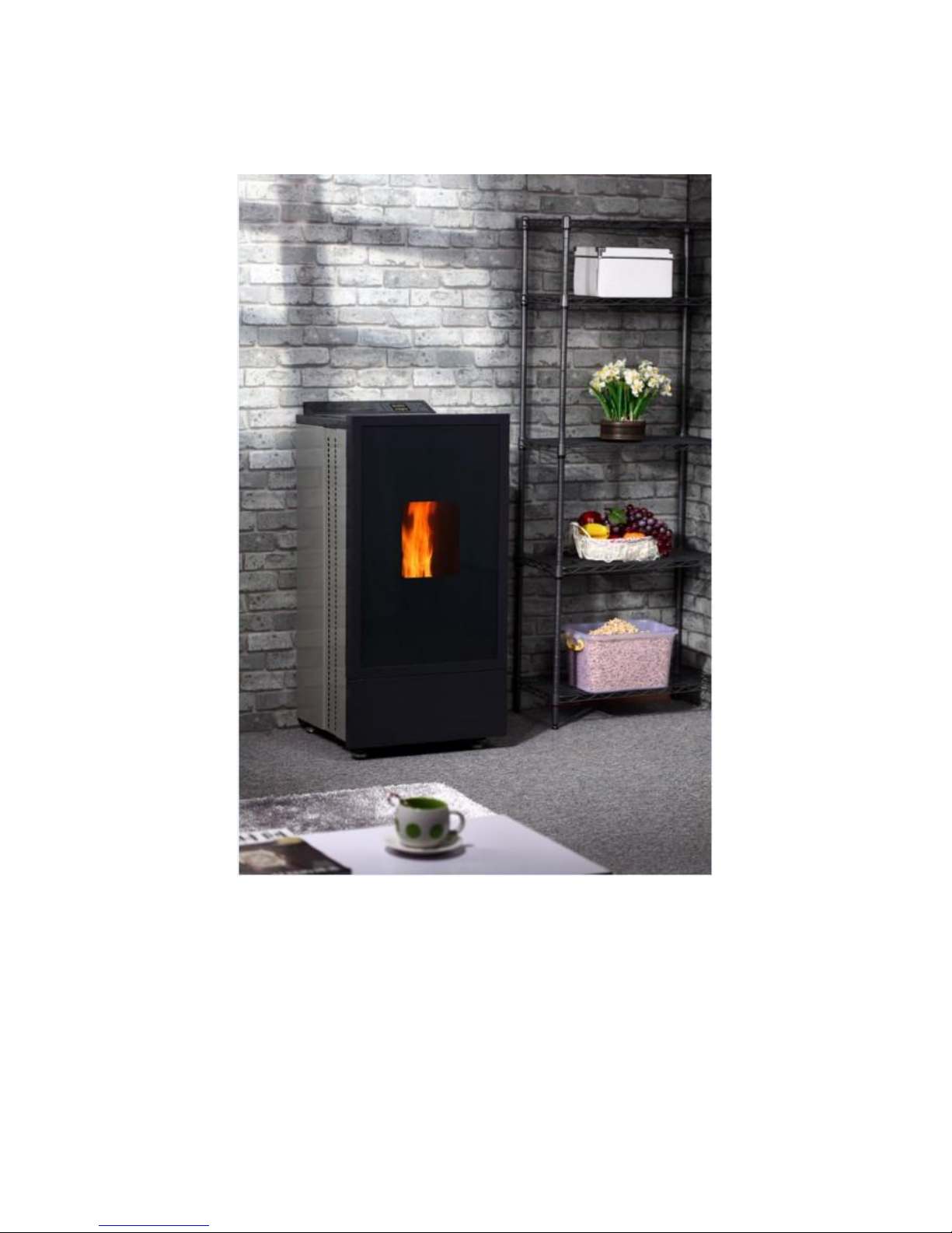
Pellet stove
-SINOLION LIMITED
USER MANUAL
MODEL:SL002
Page 2

1
Contents
1. Warning and Safety Devices ……… ……………………………….Page 2-3
2. Brief Introduction ……… ……………………………….Page 4-5
3. Technical Characteristics ……… ……………………………….Page 6-7
4. Wood Pellet ……… ……………………………….Page 8
5. Remote Control ……… ……………………………….Page 9
6. Pellet Stove ON and OFF ……… ……………………………….Page 10-11
7. Control Panel and Rear Panel ……… ……………………………….Page 12-14
8. Procedure Setting ……… ……………………………….Page 15-24
9. Wiring Diagram of Circuit Board ……… ……………………………….Page 25
10. Cleaning and Maintenance ……… ……………………………….Page 26-27
11. Smoke Channel ……… ……………………………….Page 28-29
12. Skilful Techniques ……… ……………………………….Page 30-31
13. Explore Drawing ……… ……………………………….Page 32-35
Page 3

2
CONGRATULATIONS!
We thank you for having chosen our company; our product is a great heating solution developed from the
most advanced technology with top quality machining and modern design, aimed at making you enjoy the
fantastic sensation that the heat of a flame gives, in complete safety.
The entire range of products is built in compliance with the following directives:
89/106EEC(Construction Products), 89/366EEC(EMC Directive),2004/108 CE (EMC Directive), 2006/95
CE (Low Voltage Directive), EN 14785,EN60335-2-102,EN 61000-3-3, EN 50366, EN 55014-1, EN 55014-2,
EN 303-5, EN 13240
Notes:
1. Please read the instruction book carefully before using the pellet stove of
our company.
2. Black bold contents in the instruction book are important. Please read
carefully.
3. Before using, please ensure every component is in correct position.
4. Please don’t open the door after start the stove, and don’t touch the glass
and the body of stove.
5. When you need to open the door, no less than 4 hours after turn off the
stove.
1 Warning and Safety Devices
The stoves produced by our establishment are built with attention to the individual components in a way to
protect both the user and the installer from any accidents. It is therefore recommended that after any
intervention on the product, that authorized staff pay particular attention to the electric connections, especially
Page 4

3
the stripped parts of the wires. These must not escape from the terminal board in any situation, thus
preventing possible contact with the live parts of the wire. Installation must be carried out by authorized
staff who must provide the buyer with a declaration of conformity for the system and will assume full
responsibility for final installation and as a consequence the correct functioning of the installed
product. It is necessary to bear in mind all laws and national, regional, provincial and town council
standards present in the country the appliance has been installed. The manufacturer cannot be held
responsible for the failure to comply with such precautions. The instruction manual is an integral part of
the product: make sure that it always accompanies the appliance, even if transferred to outer owners or user
or is transferred to another place, if it is damaged or lost, request another copy from the area technician. This
stove must be destined for the use for which it has been expressly realized. The manufacturer is exempt from
any liability, contractual and extra contractual, for injury/damage caused to persons/animals and objects, due
to installation, adjustment and maintenance errors and improper use. After the packaging has been removed,
check the integrity and completeness of the contents. If this does not comply, contact the dealer where the
appliance was purchased. All electric components that make up the stove must be replaced with original
spare parts exclusively by an authorized after sales centre, thus guaranteeing correct functioning. The stove
must be serviced at least once a year, programming it in advance with qualified staff and or the
manufacturer’s technical after-sales assistance.
For safety reasons, remember that:
The stove must not be used by persons (including children) with reduced physical, sensorial and mental
capacities or who are unskilled persons, unless they are supervised and trained regarding use of the
appliance by a person responsible for their safety.
Children must be controlled to ensure that they do not play with the appliance.
Do not touch the stove when you are barefoot or when parts of the body are wet or humid.
The safety and adjustment devices must not be modified without the authorization or indications of the
manufacturer.
Do not pull, disconnect, Twist electric cables leaving the stove, even if disconnected from the electric
power supply mains.
It is advised to position the power supply cable in a way that it does not come into contact with hot pars of
the appliance.
The power supply plug must be accessible after installation.
Do not close or reduce the dimensions of the airing vents in the place of installation. The airing vents are
indispensable for correct combustion.
Do not leave the packaging elements within reach of children or unassisted disabled persons.
The hearth door must always be closed during normal functioning of the product.
Avoid direct contact with pars of the appliance that tend to heat up during functioning.
Check for the presence of any obstructions before switching the appliance on following a prolonged
standstill period.
The stove has been designed to function in any climatic condition (also critical). In particularly adverse
conditions (strong wind, freezing) safety systems may intervene that switch the stove off. If this occurs,
contact the technical after-sales service and always disable the safety system.
If the flue should catch fire, be equipped with suitable systems for suffocating the flames or request help
from the fire service.
This appliance must not be used to bum waste.
Do not use any inflammable liquids for ignition.
During the filling phase do not allow the bag of pellets to come into contact with the product.
The majolica is top quality artisan products and as such can have microdots, crackles and chromatic
imperfections. These features highlight their valuable nature. Due to their different dilation coefficient,
enamel and majolica produce crackling. Which demonstrate their effective authenticity? To clean the
Page 5

4
majolica, it is recommended to use a soft, dry cloth. If a detergent or liquid is used, the latter could
penetrate inside the crackles, highlighting the same.
2 Brief Introduction
2.1 Ordinary Notice
The instruction book on installation, using and maintenance is an important part for the product. The
Page 6

5
users shall keep the book properly. Before installing, using and maintaining the machine, please read
the contents in the book carefully. It shall comply with local regulations and specifications, including
all national and European regulations and specifications. All maintenance behaviours shall be in
accordance with the book. The equipment can only be used in period of validity. Other improper
operation is not allowed, which may also cause risks. Users shall afford all losses caused by
improper operation. When taking maintenance and repair, qualified personnel are required to take
operation according to requirements of current laws and manufacturer of the product. Only part and
components produced by the manufacturer can be used when repairing and replacing the parts. The
manufacturer is exempt from all responsibilities for the injury or damage of persons, animals and
articles, which are caused by improper installation and maintenance. Make sure to cut off power
supply when clean and maintain the machine. Furthermore, the upstream equipments shall be turned
off. Fire-fighting equipments and other (power sockets) facilities for safe and correct operation of
instruments shall be installed on proper positions. Whenever changing parts or components, it must
use the parts or components manufactured by SINOLION LIMITED. Otherwise, the manufacturer will
not burden any responsibility according to related specifications. It can only use original parts of
SINOLION LIMITED. If the products are sold to other user, make sure to sell the product together with
the instruction book. SINOLION LIMITED owns the copyright of the instruction book. The
instruction book neither can be duplicated or sent to the third party without authorization of
SINOLION LIMITED nor can be used for competition.
2.2 Safety Rules
Personal Injury
Please read the important information in the instruction book when you use the pellet stove, or it may cause
enormous losses for Pellet Stove user.
Material Damage
It must comply with certain strict information and basic functions instruction. If not, it may cause severe
damages for the Pellet Stove.
Information
It the information cannot be complied with correctly, unsatisfied results may appear.
2.3 Standards and Suggestions
Suggestions:
Please read the instruction book carefully before using the product, because the understanding for
the information on the instruction book is a perquisite for correct usage of the stove. Experts with
professional training must undertake the wiring and connections of the circuit board. If the Pellet
Stove is installed, used or maintained without following the indications, the company will not be
responsible for any losses and burden any responsibility. The user or other person shall burden all
responsibilities for the products performance if the user or other person has done alterations to the
product.
Ordinary Warning:
Note: The equipment must be grounded. According to related regulations, validity of ground wire
must be checked before the equipment is installed.
Note: The power cord shall have sufficient electrical equipments. The power voltage shall be
Page 7
6
220-240V, 50HZ. It will cause irregular operation or damage the electrical equipments if more than
10% of voltage variation is existed. The equipment shall be placed in a house with proper power
supply. 10% voltage variation will cause ignition and using problems. It is also necessary to install a
circuit breaker on the upstream.
Note: Please read local notices on cooker units installation issued by Fire Force (mandatory report
and safe distance), fire insurance organizations or associations, especial for customers in Swiss.
2.4 Transportation and Storage
Transportation and Moving
The furnace stack shall be kept erectly when using a truck to deliver it. Pay special attention on
circuit board, glass and all precise parts shall be reserved properly and used correct transportation
way.
Storage
The Pellet Stove shall be placed in dry environment and be away from rain. It is not suggested to
place the Pellet Stove on ground directly. The company will not afford any losses caused by place the
Pellet Stove on wood floor or floor of other materials directly. It is not suggested to store the Pellet
Stove in warehouse too long.
2.5 Installation Requirements
It is suggested to focus the instruction in section 2.1 closely. Remember the floor must bear the weight of
Pellet Stove if it is installed on the floor in the house. Warning: Sufficient ventilation space (inlet, min 80cm2)
must be left on the places for Pellet Stove installation.
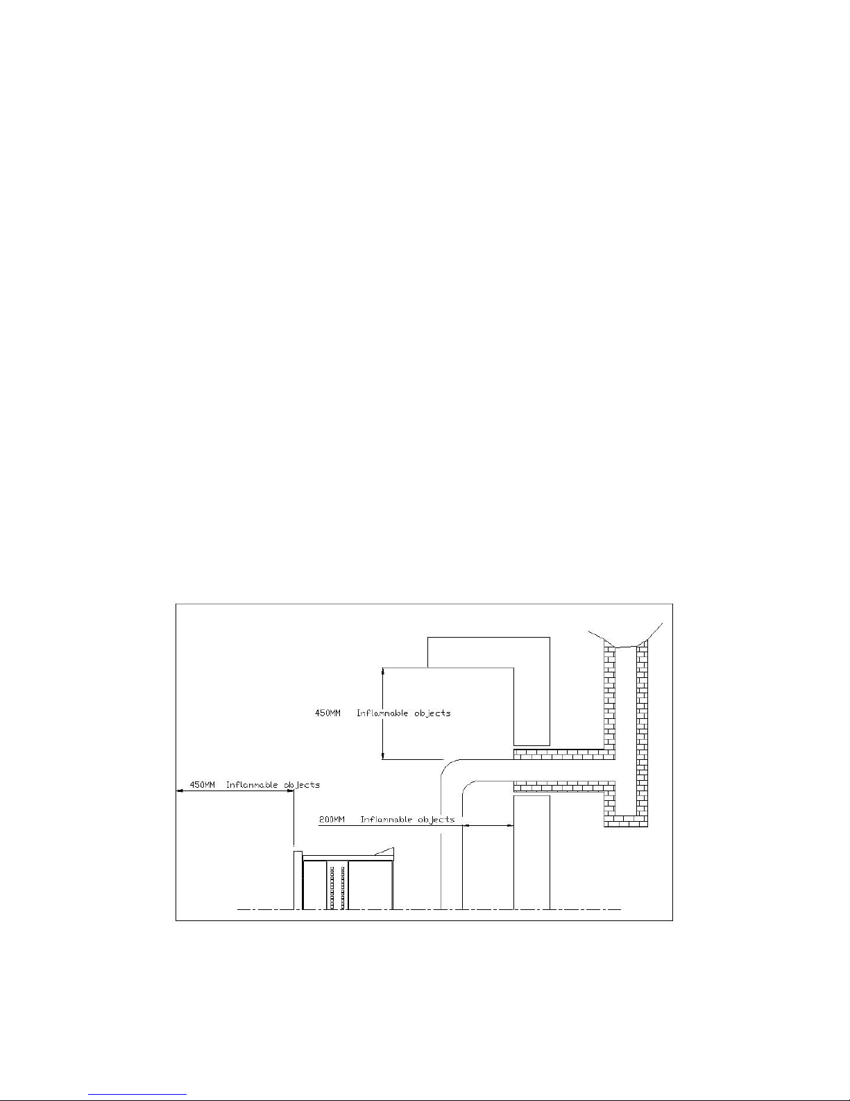
Min safe distance shall be left between the Pellet Stove and surrounded walls and furniture. If flammable
materials are placed near the Pellet Stove (such as wooden boards, furniture, curtains, pictures and couches
etc), safe distance shall be longer. On this aspect, we suggest the min distance is as in the fig 1. According to
heat-sensitive materials and installation of facilities, it shall insert proper insulation materials for protection.
Fig 1
3. Technical Characteristics
Page 8

7
Model
SL-0002
Heat output (min, max)
2.5-9KW
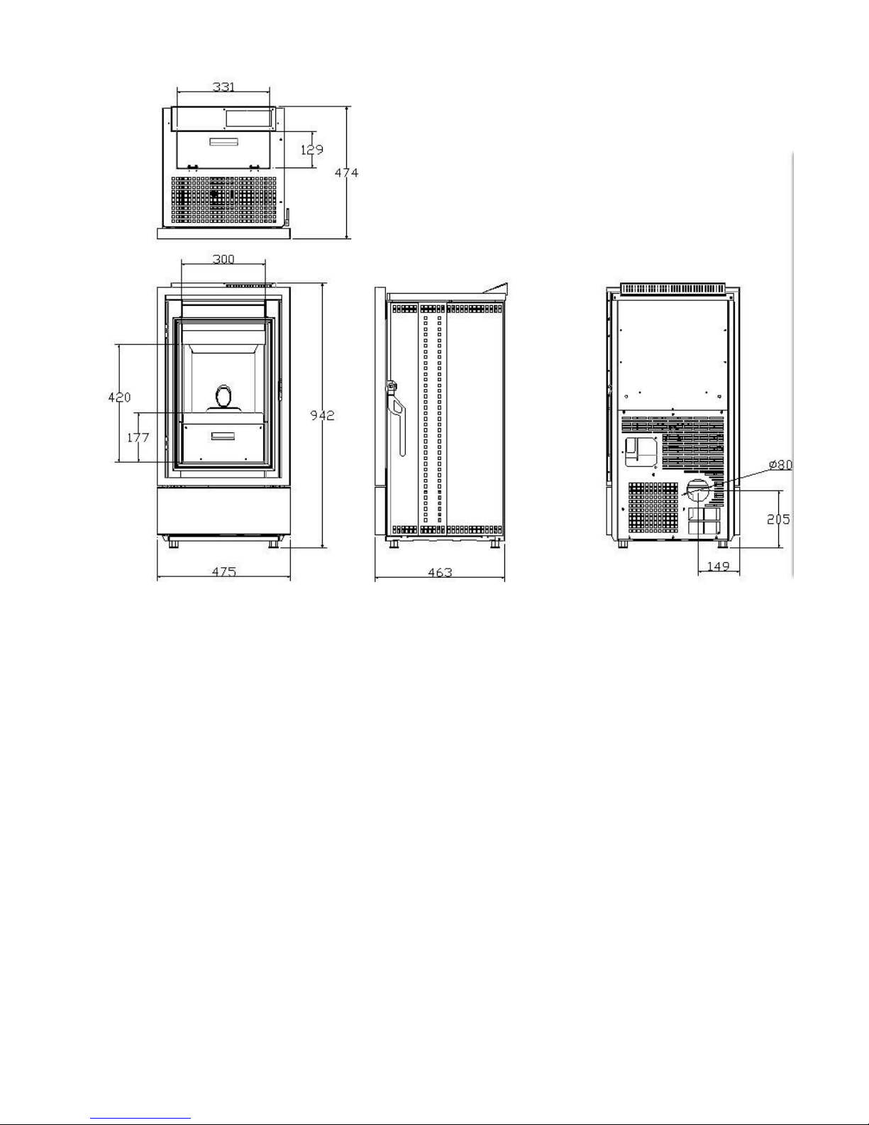
Fig 2
Page 9
8
Fig 3
Page 10
9
4. Wood Pellet
4.1 Pellet
The fuel used is called pellets; this will allow you to obtain full pleasure from the heat of the flame, without
having to manually feed the combustion. Their measurements are 6mm diameter and their maximum
length is 20mm. they have a maximum humidity content of 12%, a thermal value of 4170Kcal/Kg. the pellets
must comply with the norm DIN 51731(HP 2). Common wood with a humidity content of 10-20% has a
thermal value of 2500-3500 Kcal/Kg.
The use of fuel that is not in conformity with the one specified above shall lead to the immediate forfeiture of
the guarantee on the stove.
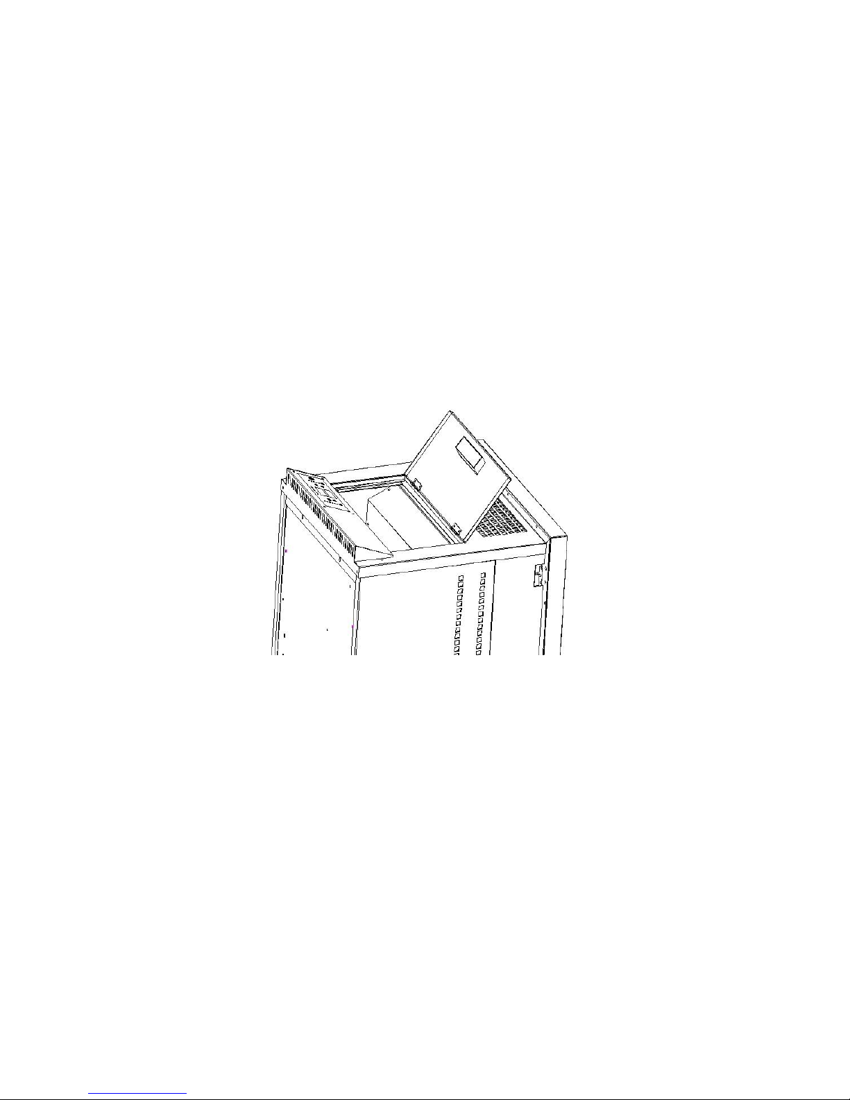
4.2 Feeding Box
Feeding box is located on the top of Pellet Stove. Max 13kg materials can be loaded in the feeding
box.
Fig 4
Page 11
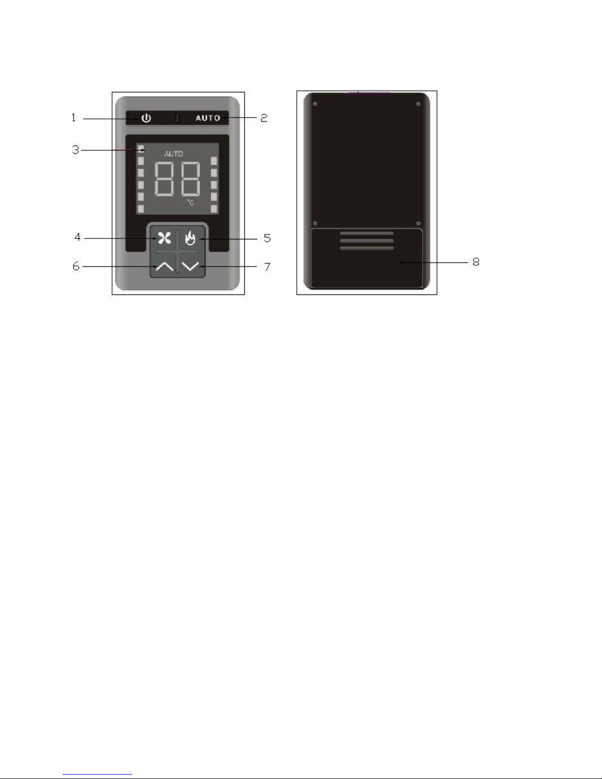
10
5. Remote Control
Fig 5
Remark: If the remote control is fail, Press button 1 and button 6 at the same time, select mode 1, or 2,
3, 4, until to use the remote control normally.
5.1 Operation of Remote Control
(1)Button <1>: Same as button 1 on control panel.
(2)Button <2>: Button <2> press will activate auto mode and the display will show AUTO.
(3)Button <4>:Ventilation setting button. Set ideal ventilation standards by pressing covert button to
select the most proper level among the 6 levels. (It has 6 levels totally, and 6th level is the top level. It
can set ideal level by pressing button 4 repeatedly.
(4)Button <5>:Power setting button. Set ideal power standards by pressing covert button to select the
most proper level among the 5 levels. (It has5 levels totally, and 6th level is the top level. It can set ideal
level by pressing button 5 repeatedly).
(5)Button <6> and <7>: Ambient temperature setting buttons. Set the ideal ambient temperature by
pressing buttons <6> and <7>. The lowest temperature can be set to 16 degree and highest 30 degree.
Note: Set temperature only can be valid in AUTO mode.
5.2 Battery Installation and Replacement
Open the battery cover 8 and install or replace two 7# batteries.
The following is about the function of each button on the remote control.
1:Start-up button
2: Start automatic mode.
3: Display area: including ventilation level display, function level display, ambient
temperature display and auto mode display.
4: Ventilation set button
5: Power set button
6, 7: Ambient temperature set button: To set ambient temperature in auto mode, you can use
button 6 and 7 to set ideal temperature.
8: Battery cover
Page 12
11
6 Pellet Stove ON and OFF
6.1 Pellet Stove ON
Before using the Pellet Stove, check whether all parts are in places. Remove all glass adhesive materials and
labels at the same time to prevent existed permanent marks.
Operation:
(1)Connect power cord.
Initial status screen will display “STAR”. If it does not display STAR”, press button 6 repeatedly until
STAR is displayed, (Fig 6, 029 in the lower picture means the ambient temperature is 29 degree). When the
operation is started, the first pellet will be dropped after several minutes’ combustion, because there is no
material in the feeding motor.
Note: Within 25 min of ignition stage (Word “Star” is displayed on the screen.), the Pellet Stove will
ignore all transmission orders and the power level and ventilation level cannot be regulated.
However, button (6) can be pressed to enter main menu to set time, date, appointment time, mode and
language etc.
(3)When the screen display ON, stove can be set
After the machine is started 25 min, the fan will be started and temperature of the Pellet Stove will surpass
42℃. Then the screen will display ON. And the power and ventilation buttons can be adjusted. Use 5 Led’s
on the right to set power (by pressing button 15) repeatedly. Lev 1 is the lowest level and Lev 5 is the top
level.). You can see the 6 Led’s on the left are used to indicate the speed of room ventilation and by
pressing button 2 repeatedly you can adjust it. Lev 1 is the lowest level and Lev 6 is the top level.).
Note: Slight vibration is normal when the Pellet Stove combust materials.
Fig 6
Page 13
12
6.2 Pellet Stove OFF
Operation
(1) Press button (1) one time
The screen will display ON or START. If it does not display ON or START, press button 6 repeatedly until it
displays ON or START. (Fig 7 and 8, 029 in the lower pictures mean the ambient temperature is 29 degree).
Fig 7 Fig 8
(2) The screen displays OFF, as in Fig 9.
Note: Power-off is not allowed in this case, you can pull off power cord no less than 1 hour
Fig 9
(3) Power switch 16 is switched to “0” position after 1 hour.
Feeding motor starts to stop feeding and the smoke exhaust fan continues running, Wood pellet in the brazier
is burned out gradually and the temperature is lowered.
Page 14
13
Note: It is better to unplug power cord after the Pellet Stove stopped for at least 4 hours so it has
cooled off completely..
7 Control Panel and Rear Panel
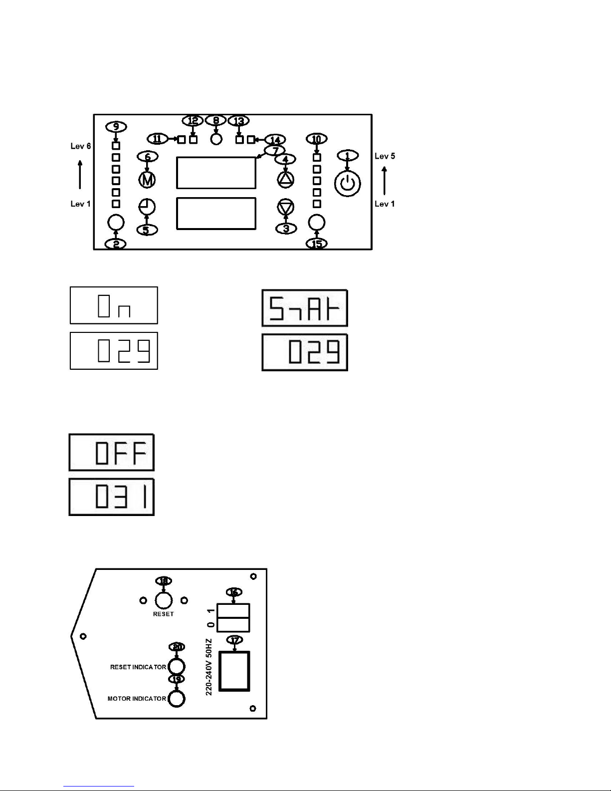
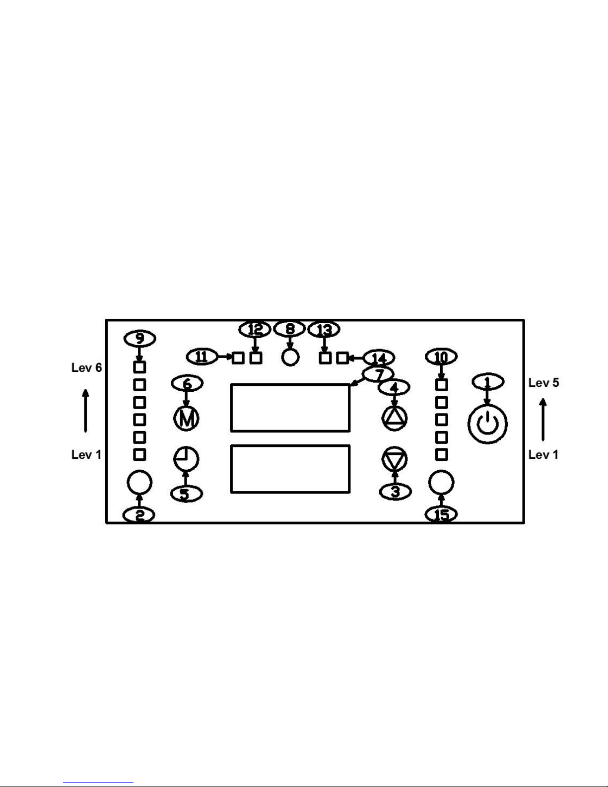
7.1 Control Panel
Two main command buttons are used for ventilation and power setting. Press corresponding buttons to set
Pellet Stove.
Power setting has 5 levels allocated in accordance with intensity (by pressing button 15 repeatedly.
Lev 1 is the lowest level and Lev 5 is the top level.). When the max temperature of Pellet Stove is higher
than 42℃, it will be run normally.
Ventilation setting can be regulated to max 6th level (by pressing button 2 repeatedly. Lev 1 is the
lowest level and Lev 6 is the top level.). During operation process of Pellet Stove, ventilation command
cannot be closed. 。
Fig 10
7.2 Button and Indicator
Functions of each button are described as the following:
(1)Start-up switch: The Pellet Stove is started after power on. Shut off the machine.
(2)Ventilation setting button: Set ideal ventilation standard by pressing the buttons to select the most
proper button among 6 levels.
(3)( 4)Auxiliary setting button: It is necessary for procedure setting, work setting and clock setting of the
machine.
(5)Appointment procedure ON/OFF button: After setting appointment time, press the button 5 and the
appointment time indicator will be ON, which indicates appointment time is in normal condition. If it is not ON,
in means the appointment time has been shut off.
Page 15
14
(6)Menu selection button: main menu button 6. Press button 6 repeatedly to set date, time, mode,
procedure and other display windows.
(7)display area
(8)Infra-red sensor: Take remote control using remote control. It shall aim at the infrared sensor when
using remote control.
(9)Ventilation level indicator: Lev 1 is the min level and Lev 6 is the max level.
(10)Power level indicator: Lev 1 is the min level and Lev 5 is the max level.
(11)Appointment time indicator: After setting appointment time, press button 5, the indicator will be on,
which means the appointment setting is valid.
(12)Air switch indicator: After the machine is started, the indicator is ON, which means the air switch is in
normal condition.
(13)High temperature auto control switch indicator : The indicator will be ON when the temperature
on the stove surface is higher than 90 degree. Adjust the power level to Lev 1 and Ventilation level to Lev 6
until the stove surface temperature stays below 90℃ and the indicator will not light up. When the indicator is
on you are no longer able to increase the power of the stove.
(14)42 degree temperature control switch indicator: When the temperature of the metal chamber
reaches 42 degrees the unit is aware that the pellets have ignited and combustion of the pellets is smooth
and producing heat. After the screen display is changed from STAR to ON, the indicator is ON, which means
power setting and ventilation setting can be adjusted.
(15)Power setting and editing button: Set ideal room standard by button press. Select the most proper
button among 5 levels according to corresponding temperature prompt. Meanwhile, it is also an editing
button. After editing information, press button 15 to confirm and save edited information. Then take the
following operation. If it does not press button 15 to confirm the information and press the button 6 when
editing the information, it means give up modification for edited information directly and exit edition.
Note: Set the power level and ventilation level following the rules below
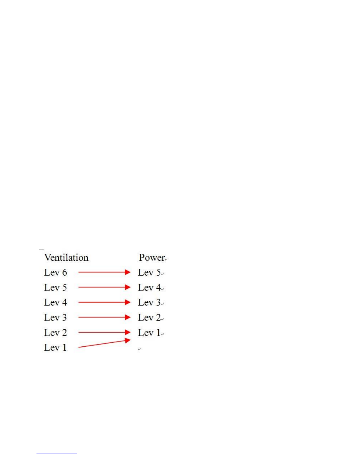
When the power level is Lev 1, the ventilation level could be Lev 1 or Lev 2
Page 16
15
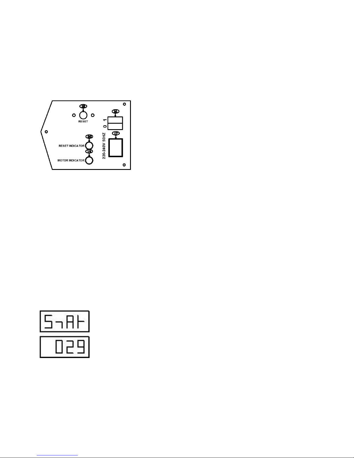
7.3 Rear Panel
The following information is on icons on rear panel:
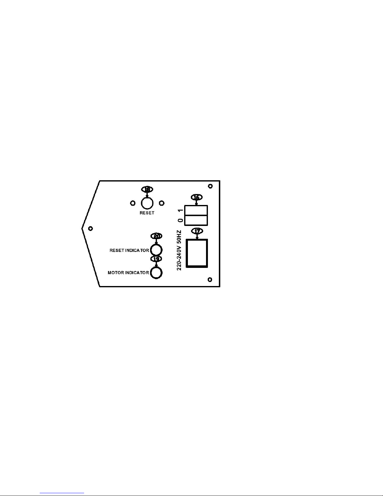
(16)Power switch0/1: Before start-up , switch to position 1.
(17)Power socket of Pellet Stove 20-240V/50Hz: power cord socket
(18)RESET: material-stuck reset switch( with plastic cap), It is a protecting device, At 125 degrees, the
sensor in the fuel conveyor system activates the alarm and stops the feeding of pellets , or when the feeding
motor is in normal operation condition, then the feeding motor is stopped running. Use material-stuck switch
to reset the alarm. Shut down the machine and find out the problem triggering of material-stuck. Restart the
machine after solving the problem.
(19)MOTOR INDICATOR:Normal operation indicator (It is normal for the indicator is ON when under
non-material-stuck condition.
( 20 ) RESET INDICATOR:Material-stuck alarming indicator
Fig 11
Page 17
16
8 Procedure Setting
8.1 Main Menu
After connecting with the power, power switch of Pellet Stove is at position “1”. Start the Pellet
Stove, and the screen will display “STAR”. If it does not display STAR”, press button 6 repeatedly
until STAR is displayed.
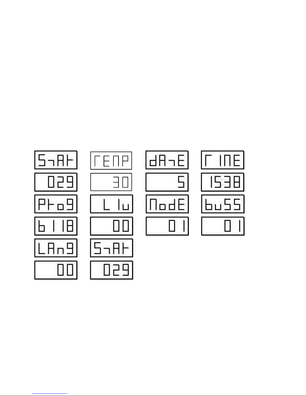
When pressing button 6 to enter main menu: (press button 6 one time, enter next procedure)
STAR/ON 》 TEMP 》 DATE 》 TIME 》 PROG 》 LIU 》 MODE 》 BUSS 》 LANG 》 STAR/ON,
successively to complete a cycle.
When corresponding display is on the screen, press button 15 to edit information. Press button 3 and
button 4 to set different values. After setting is completed ,press button 15 again for confirmation.
Save edited information and press button 6 again for following operation, press button 6 repeatedly
to back to initial display status of STAR/ON.
》》 》》 》》 》》
》》 》》 》》 》》
》》
Fig 12
Page 18
17
8.2 LED Display Information
The following description is on LED display information:
Fig 13
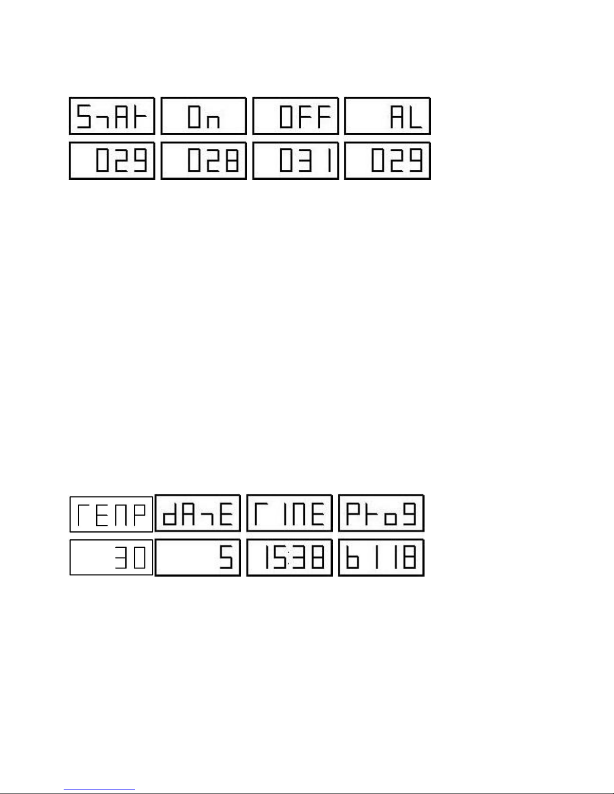
Display information in Fig 13 above:
STAR: Start-up condition, 029 displayed by LED display is the current ambient temperature. Press button 1,
and the screen displays Star.
ON: Normal condition,,028 displayed by LED display is the current ambient temperature. 25min after start-up,
the screen will display On.
OFF: OFF condition, 029 displayed by LED display is the current ambient temperature. The screen will
display OFF when the machine is shut off.
AL: Alarming condition. 029 displayed by LED display is the current ambient temperature. The screen will
display AL when abnormal condition is appeared during operation.
Then the feeding motor will stop feeding materials, and the smoke exhaust fan is in normal operation.
The Pellet Stove will be stopped automatically when the wood is burned off.
Wait until the temperature is lowered, and switch the power switch to position “0”. Disconnect the power.
Check the malfunction of machine after the temperature is lowered. If the problem cannot be solve,
please contact professional personnel to debug the problem before using.
Note: after the alarm is removed, switch the power switch 16 to position “0” to disconnect the power.
Switch it to position “1”. Restart the machine. Otherwise, the Pellet Stove cannot be started.
Fig 14
Display information in Fig 14 above:
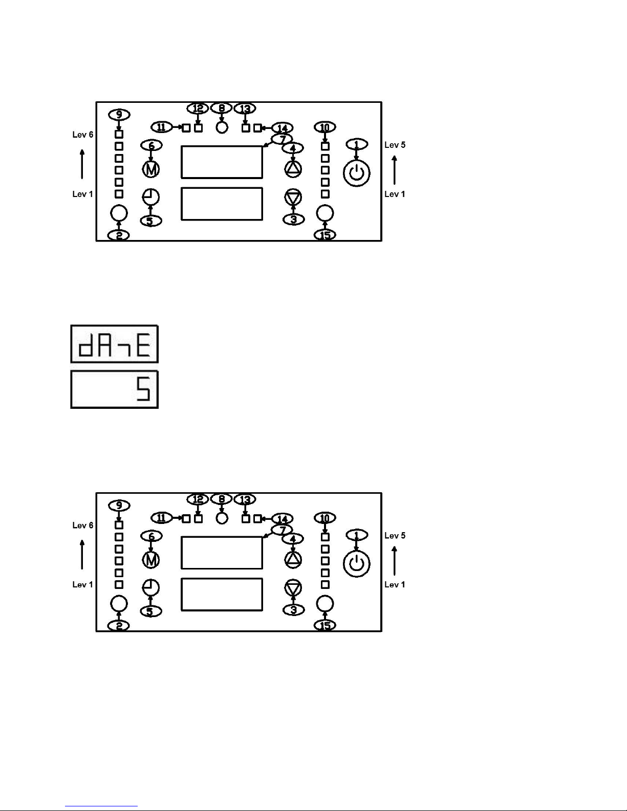
TEMP: Temperature display screen of operation condition in Auto mode. 30 is the set max ambient
temperature in auto mode.
DATE: Date setting. It can set from Monday to Friday. Number 5 means Friday.
TIME: Time setting, 15:38 is the current time.
PROG: Appointment time setting,,b118 is the program version.
Page 19
18
Fig 15
Display information in Fig 15 above:
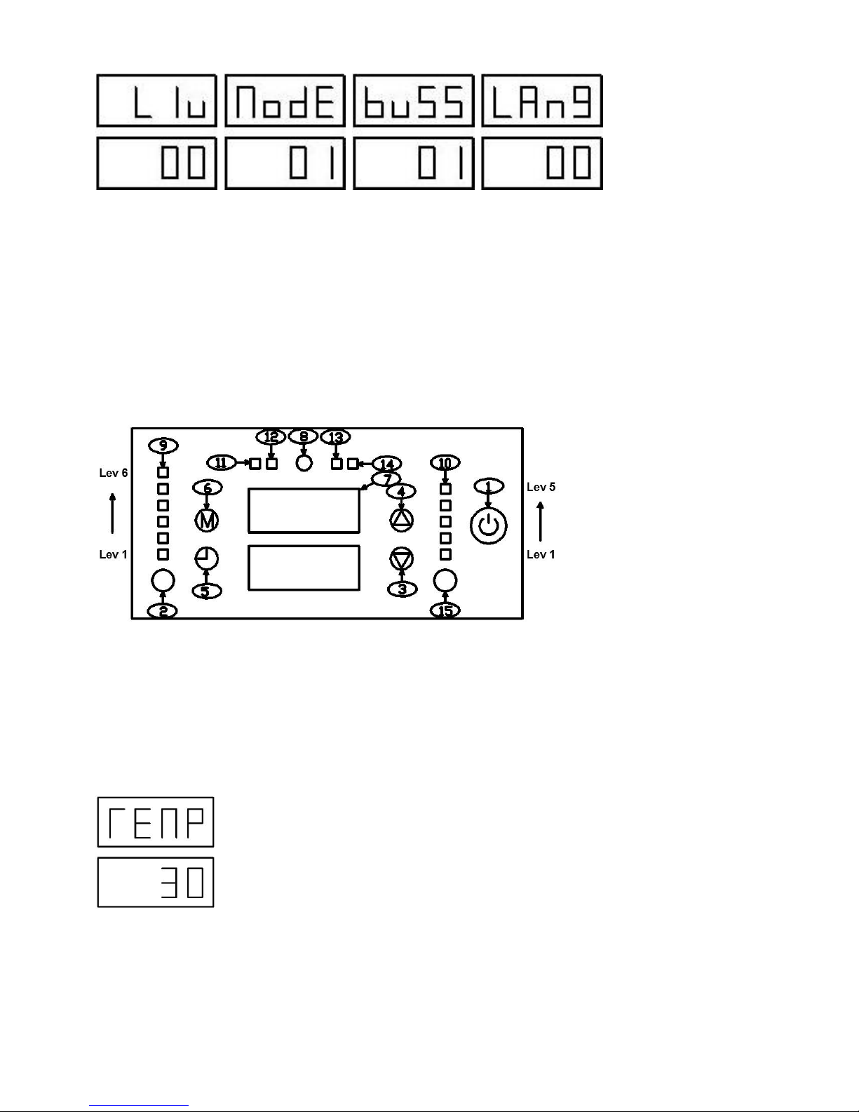
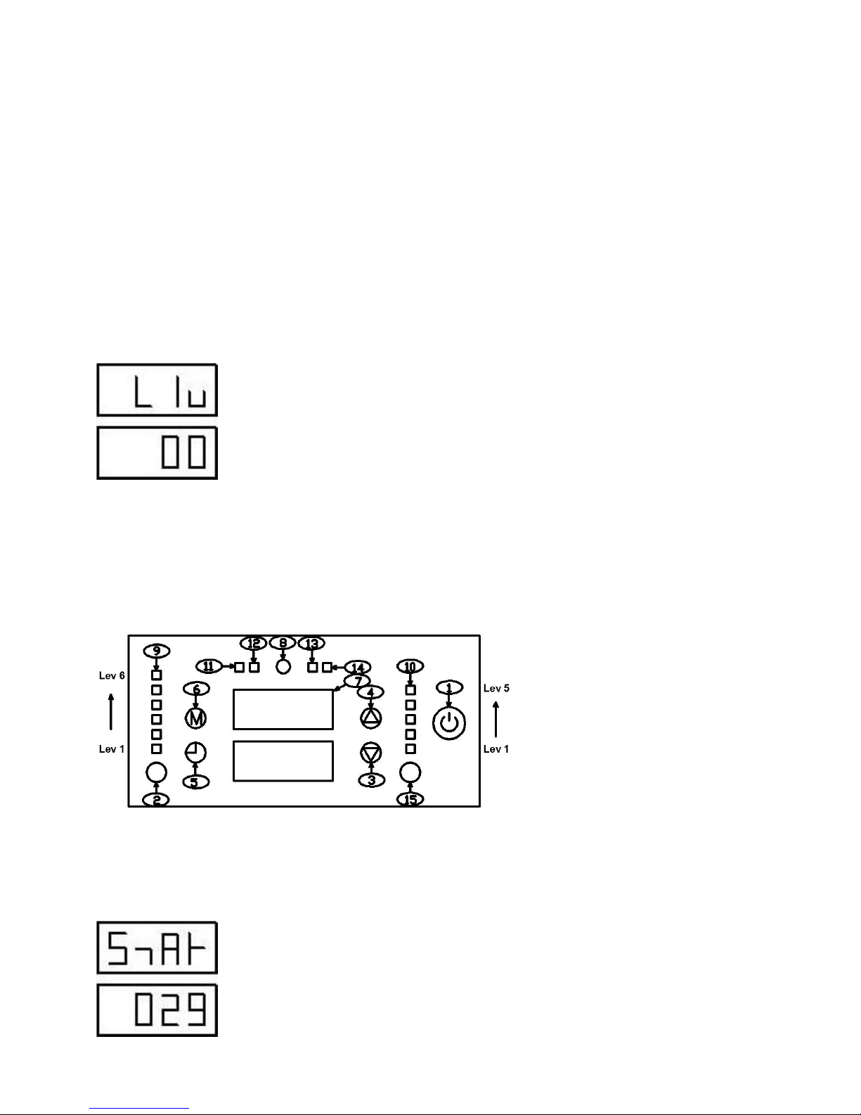
LIU: It displays the level in operation mode. 00 means in 0 level.
MODE: It displays operation mode setting. 01 means in Auto mode (Fig 22), and 00 means in Manual Mode
(Fig23).
BUSS: It displays buzzer condition. 00 means the buzzer is OFF and 01 means the buzzer is ON.
LANG:It displays language information, 00Enlish, 01Spanish, 02 Italian.
8.3 Temperature Setting in Auto Mode
Operation
(1) Press button 6 until word ‘TEMP’ is displayed on the screen, see below Fig 16
(2) Press button 15 one time, ‘30’ shining
(3) Press button 3 or 4 to modify the temperature
(4) Press button 15 one time to complete the modification
When forget to press button 15 confirm, the setting will be invalid. Please set again. The temperature
can be set in a range of 16-30 degree.
Note: Set temperature can only be valid in Auto mode.
As in Fig 16, current setting temperature is 30 degree.
Fig 16
Page 20
19
8.4 Date Setting
Operation
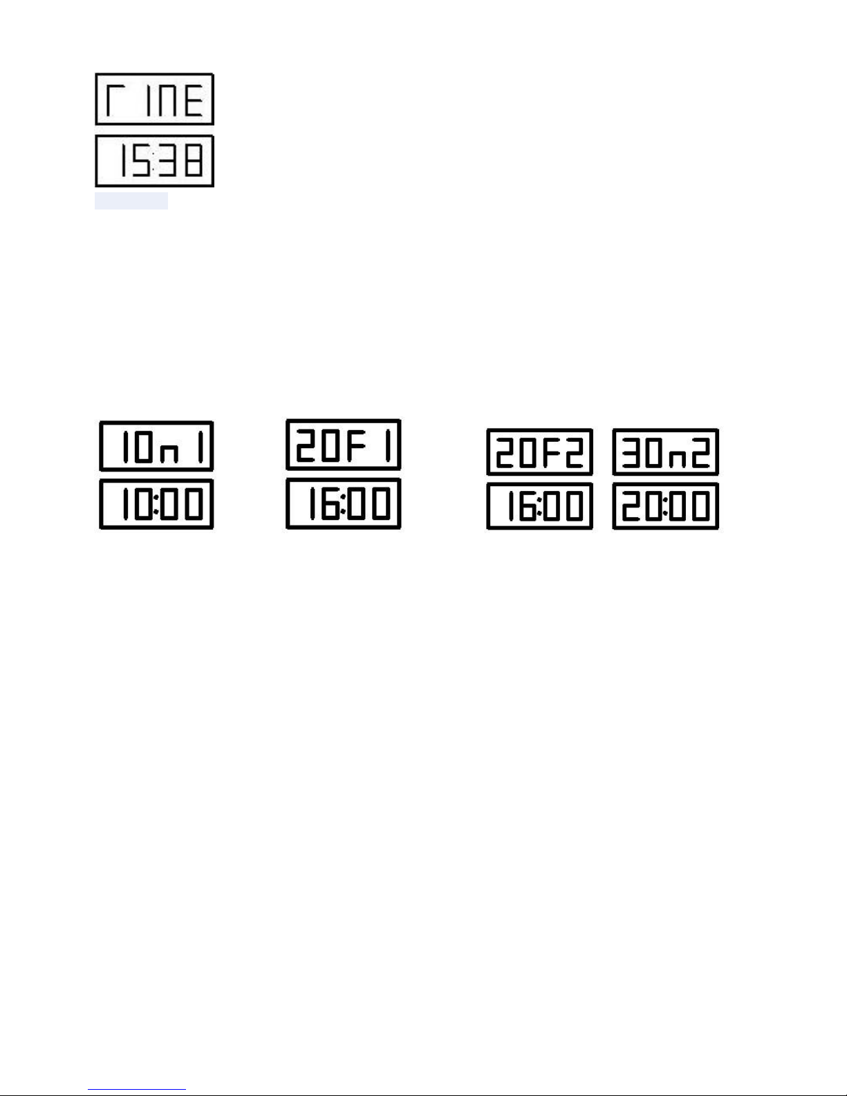
(1) Press button 6 until word ‘DATE’ is displayed on the screen, see below Fig 17
(2) Press button 15 one time, ‘5’ shining
(3) Press button 3 or 4 to modify date
(4) Press button 15 one time to complete the modification. The date can be set in a range of 1- 7.
As in Fig 17, current set date is Friday.
Fig 17
8.5 Time Setting
Operation
(1) Press button 6 until word ‘TIME’ is displayed on the screen, see below Fig 18
(2) Press button 15 one time, ‘38’ shining
(3) Press button 3 or 4 to modify minute
(4) Press button 15 one time to confirm the minute
(5) Press button 3 or 4 to modify hour
(6) Press button 15 one time to complete the modification.
As in Fig 18, current set time is15:38.
Page 21
20
图 18
8.6 Appointment Time Setting
8.6.1 Appointment time can be set from Monday to Sunday every week. Three appoint times can be
set every day.
Note: The time only can be set as 24 hour (from 01 to 24); Appointment time cannot have clashing
time settings (i.e. one setting must follow the other in a sequence.). (e.g
. If the first appointment time
is 10:00-12:00, then the second appointment time can be any time excluded 10:00-12:00, such as 14
:
00-16:00. 11:00-14:00 is not allowed.
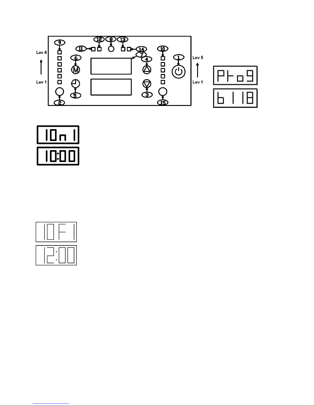
8.6.2 Appointment Time Display Instruction:
Fig 19 Fig 20 Fig 21
For Fig 19, in the first line ““10n1”: 10 means the first appointment time, n means the machine is ON,
and 1 means Monday.
The second line: it means the time is 10:00.
The Fig 19 indicates the first appointment time on Monday is 10:00 am.
For Fig 20, in the first line “20F1”: 20 means the second appointment time, F means the machine is
OFF, and 1 means Monday.
The second line: it means the time is 16:00..
The Fig 20 indicates the second appointment time on Monday is 16:00 pm.
The rest can be deducted in the same way.
In Fig 21, when the display area shows “20F2”, it means the second appointment time on Tuesday is
16:00 pm.
When the display area shows “30n2”, it means the third appointment time on Tuesday is 20:00 .
Page 22
21
8.6.3 Appointment time operation
(1) Press button 6 until word ‘PROG’ is displayed on the screen, B118 means version
(2) Press button 3 one time, below displayed
(3) Press button 15 one time, ‘00’ shining
(4) Press button 3 or 4 to modify minute
(5) Press button 15 one time to confirm the minute
(6) ‘10’ shining
(7) Press button 3 or 4 to modify hour
(8) Press button 15 one time to confirm the hour
(9) Press button 3 one time, below displayed
(10) Press button 15 one time, ‘00’ shining
(11) Press button 3 or 4 to modify minute
(12) Press button 15 one time to confirm the minute
(13) ‘12’ shining
(14) Press button 3 or 4 to modify hour
(15) Press button 15 one time to confirm the hour
(16) The first appointment time finish
After finish the first appointment time,
Press button 6 one time, enter main menu,
Press button 3 one time, enter the second appointment time setting, same as the first time setting.
Note: To make sure the appointment time is effective, the following aspects must be paid attention to:
1. Power switch 16 must be at position “1”, and the Pellet Stove must be in power-on condition.
2. After setting appointment time, it must press button 5, and indicator 11 is ON, thus the
appointment time is effective.
3. Appointment time cannot be activated at 00:00 every day. Any appointment time among the three
Page 23
22
appointment times cannot be set at 00:00.
8.6.4
If the user does not intend to use appointment time, press button 5 and the indicator 11 will be OFF,
which means the appointment time is shut off. The user can also set the appointment at 00:00 if he does not
intend to use appointment time. The appointment time is only effective when the procedure button indicator is
On, Combustion system (combustion level and fan speed) is a preset system before the Pellet Stove is shut
off. If the system is hut off manually, (furthermore the operation is effective), then the following switch will be
positioned at Lev 1 for combustion power and fan speed through editor operation. When the ignition system
is started, make sure the brazier is clean and placed position is correct.
8.7 Working Mode
Working mode, as below Fig 22.
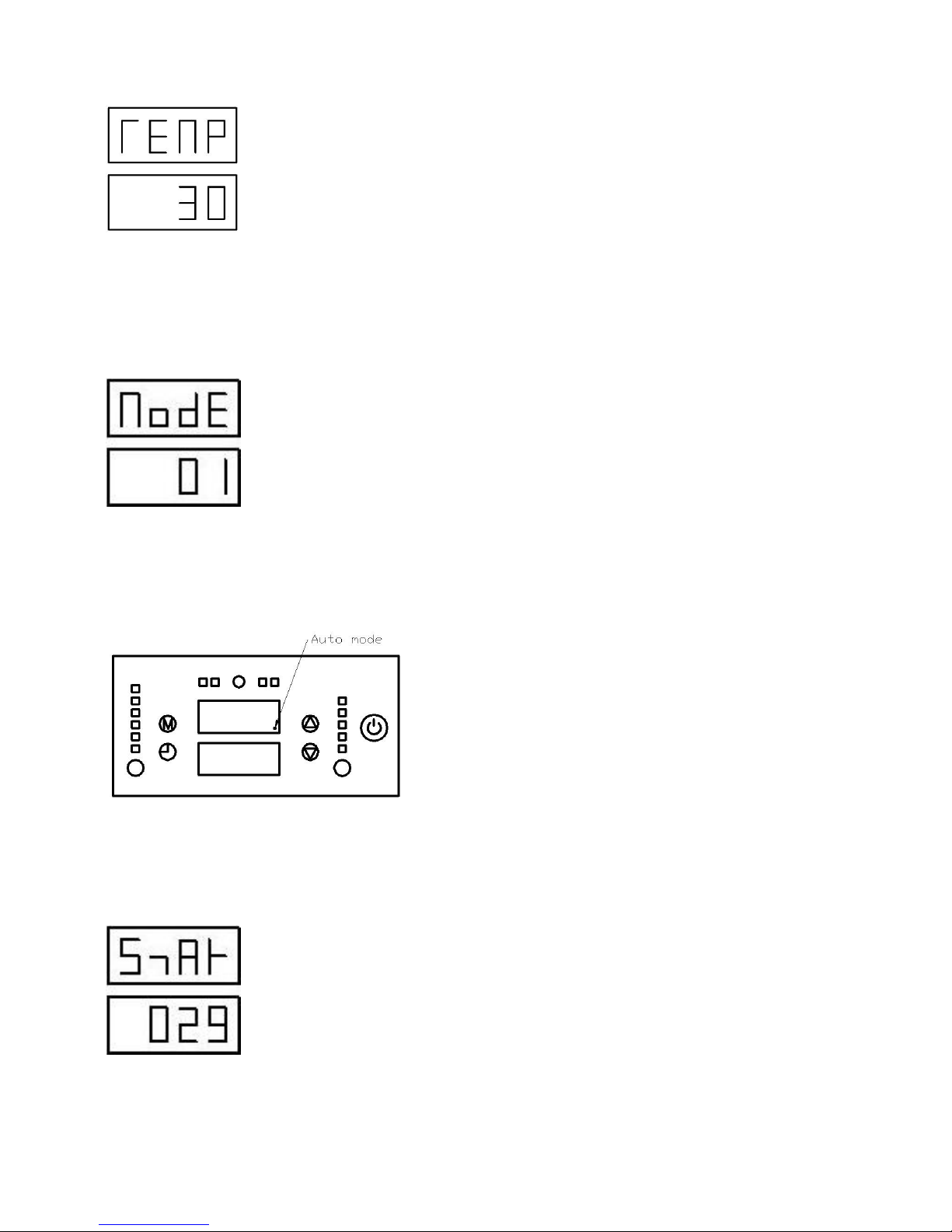
00: Normal working mode, 00 is the default mode. ( 01 indicates AUTO mode )
Fig 22
8.8 Auto /Manual Mode Setting
When setting auto/manual mode, select one of the following operation:
Remark: The second operation is simple.
8.8.1 One of Operation:
(1) Press button 1 one time
(2) Display “Star”:
(3) Press button 6 one time
Page 24
23
(4) Display “TEMP”
(5) Press button 15 one time
(6) “30” will be shining and can be modified
(7) Press button 3 or 4, setting temperature what you want
(8) Press button 15 one time, modified finished
(9) Press button 6 for 10 times, until “MODE” display on the screen
(10) Display “MODE”
(11) Press button 15 one time
(12) “00”or “01”will be shining and can be modified
(13) Press button 3 one time,
(14) Display “01”
(15) Press button 15 one time, modified finished
Fig 24:When auto mode is activated, fixed point will appear.
8.8.2 The other operation:
(1) Press button 1 (on the panel)
(2) Display “Star”
(3) Press button 6 or 7 (on the remote), set the temperature
(4) Press button 2 ((on the remote, Auto disappear on the screen of remote control)
(5) Finished
Page 25
24
8.9 Buzzer Setting
Operation
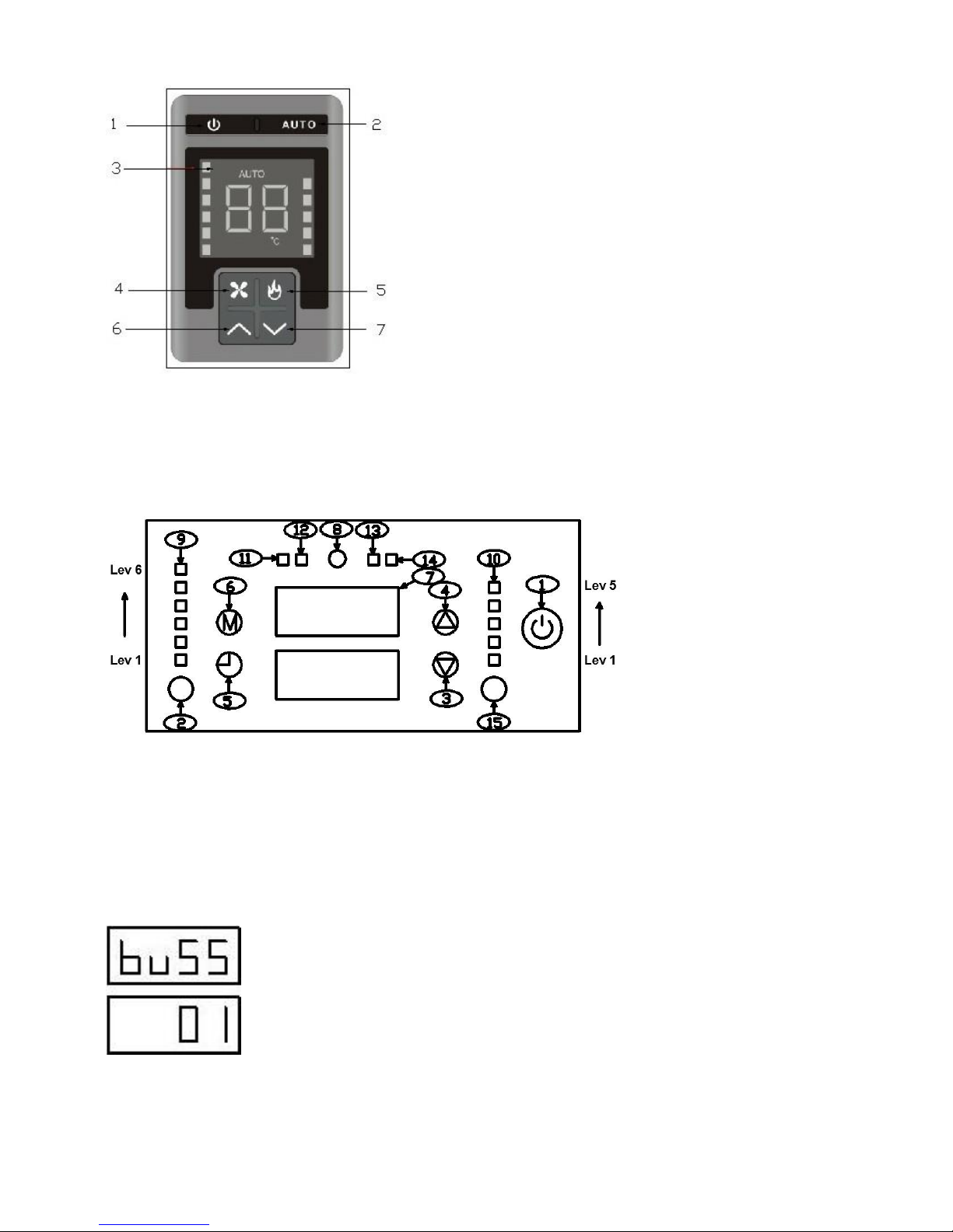
(1) Press button 6 until word ‘BUSS’ is displayed on the screen, see below Fig 26
(2) Press button 15 one time, ‘01’ or ‘00’ shining
(3) Press button 3 one time to modify
(4) Press button 15 one time to complete the modification.
Note:
The first line: BUSS means buzzer
The second line: 00 means ON, 01 means OFF
As in Fig 26, the buzzer is OFF in this case.
Fig 26
Page 26
25
8.10 Language Setting
Operation
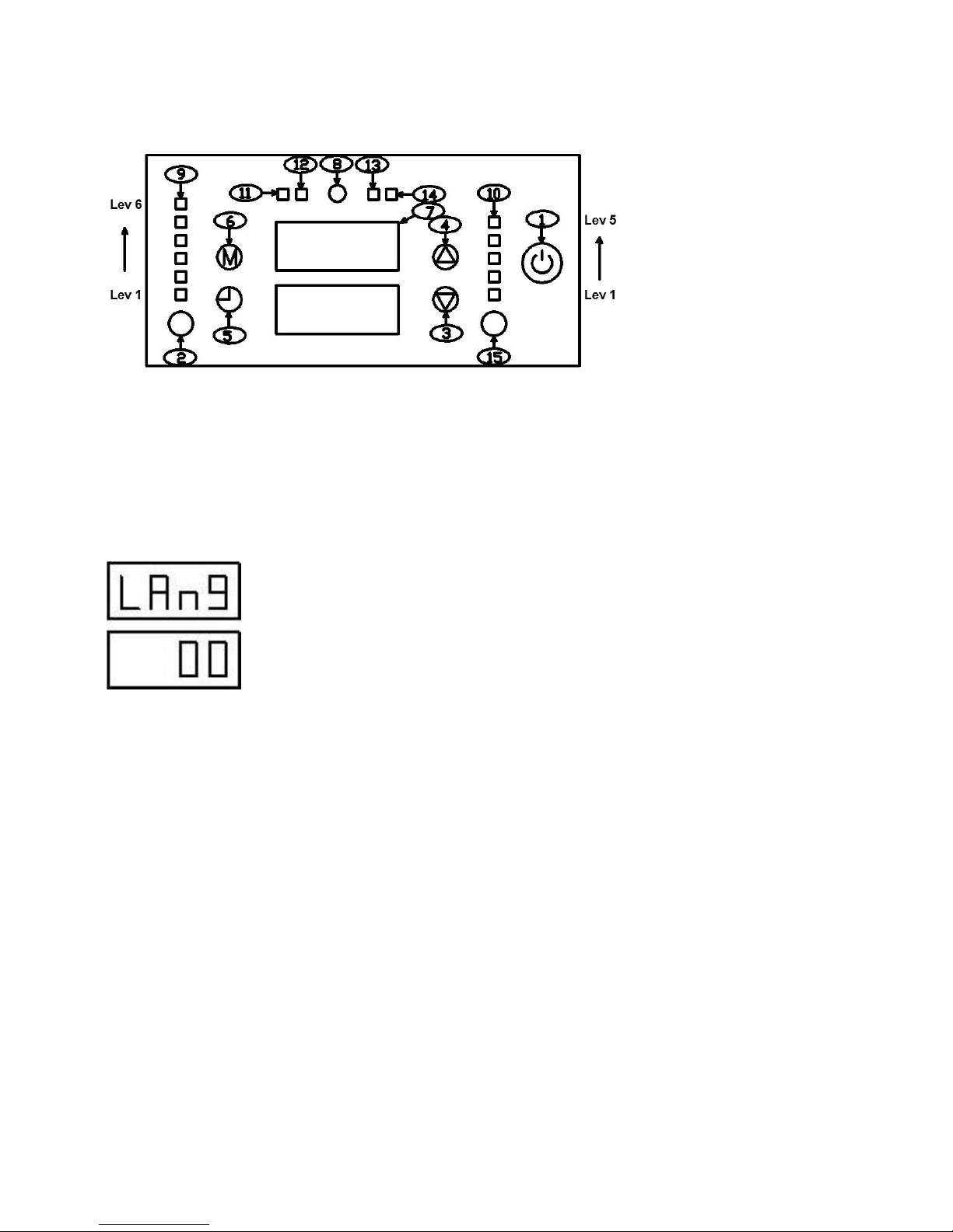
(1) Press button 6 until word ‘LANG’ is displayed on the screen, see below Fig 27
(2) Press button 15 one time, ‘00’ or ‘01’ or ‘02’ shining
(3) Press button 3 or 4 to modify
(4) Press button 15 one time to complete the modification.
Note:
The first line: LANG means language
The second line: 00 means English, 01 means Spanish, 02 means Italian
As in Fig 27, the language is English in this case.
Fig 27
Page 27
26
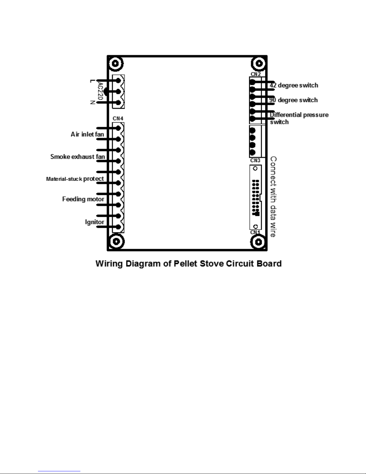
9. Wiring Diagram of Circuit Board
Fig 28
【Left】Air inlet fan : Take indoor air exchanging.
Smoke exhaust fan : Exhaust discharge gas.
Material-stuck protection : Ensure smooth feeding.
Feeding motor : Operate feeding device.
Igniter : Heat the pellet
【Right】42℃ thermostat
90℃ thermostat
Differential pressure switch
Page 28

27
10 Cleaning and Maintenance
10.1 Notes
Make sure the Pellet Stove is turned off and power supply is powered off before cleaning it. Clean the
machine after the Pellet Stove is cooled.
The Pellet Stove you used is adopted pellet fuel, and solid fuel is often used. Therefore, to ensure normal
operation and excellent performance of the machine, common operation control and cleaning is necessary.
Under the condition of long period of operation, check the resistance produced by smoke channel before
using. It shall comply with the following specifications strictly, otherwise, it may cause serious injury to the
brazier motor cleaning personnel of the plant and user party.
10.2 Airproof Gate Opening and Closing
Fig 29
Airproof Gate Opening and Closing: as in Fig 29, Open and Close.
10.3 Cleaning and Maintenance of Pellet Stove
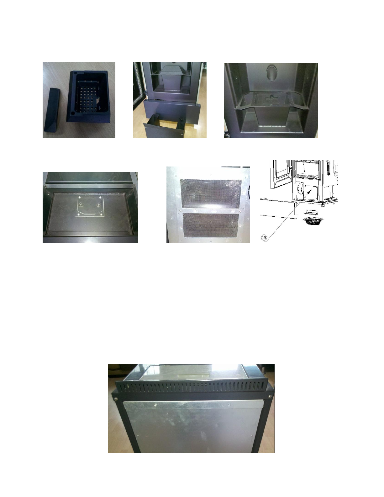
Clean the combustion residue of brazier daily and clean brazier and baffle properly. (Fig 30)
Pay attention to clean brazier before start-up every time and use aspirator to clean combustion room.
Empty residue ash in ashtray every two days (Fig 31).
Take out the brazier and aspirate residual ash weekly (Fig 32).
Clean the glass weekly. Ensure the glass is cooled when cleaning it. It must use wet cloth and newspaper to
clean the glass. Use wet cloth to wipe ash until it is clean completely.
Clean the entrance of furnace smoke channel every two weeks.
Check and clean outlet opening monthly, as in Fig 33. Unscrew the cover and unscrew 2 fixed screws, thus
the cover plate under the spring can be dismantled.
Clean dust-proof net of inlet motor monthly according to the instructions in Fig 34. Unscrew 2 fixed screws
and dust-proof net can be dismantled.
Check the ash in the channel monthly, especially at the beginning.
Aspirate pellet powder at the bottom of feeding box monthly.
Once a month, check and clean the below flue gas channel, unscrew 4 fixed screws, remove the cover plate.
(Fig 39), clean and remove ash.
All these tidy works shall be done at the end of every winter. (Use brushes and aspirator according to
cleaning methods.)
It shall clean the discharge gas tube and smoke pipe twice every year. Use aspirator to clean ash.
Never clean glass during moving the Pellet Stove. The side plate shall be cleaned with soft and wet
Page 29
28
cloth when the Pellet Stove is cooled. Note: It normal for smoke and dust and combustion residue
left on the glass every day.
Fig 30 Fig 31 Fig 32
Fig 33 Fig 34 Fig 39
10.4 Remote Control Battery Replacing
When the infrared remote control cannot transmit signals (Light-emitting diodes), it must replace batteries in it.
Open the batteries cover and replace the batteries. It shall ensure to use safe method to take out the
batteries.
10.5 Control Panel Backup Batter Replacing
When the procedure cannot be memorized continuously, it must unscrew two screws at the back of upper
cover and replace batteries with the same model. It shall ensure to use safe method to take out the batteries,
as the Fig 35.
Fig 35
Page 30

29
11 Smoke and the Chimney requirements
Accidents are frequently caused by the smoke or chimney problems in the house. We propose the following
suggestions to adjust the task of procedure installation and check whether smog produced by combustion is
eliminated. The smoke discharge has shall comply with the specifications in UNI7129/92, UNI10683 and
EN14785. It must comply with the above instructions. Malfunction may cause serious injury and damages for
product, the manufacturer, materials and the user.
11.1 Ventilation of the Residence
•In the house, the Pellet Stove installed can ensure good air quality, and ensure the combustion of air in Pellet
Stove and ventilation in the rooms, which are most important. Natural flowing air must be discharged out through
fixed vents through the room walls or individual or collective ventilation pipeline.
Circulated air must be far away from pollution sources. It is also allowed to get air from the vents of adjacent room
indirectly.
• Openings on the wall must meet the requirements:
- Internal wall and external wall of openings cannot be blocked.
-It shall be set at a height close to the ground.
Adjacent room can also provide • Airflow volume.
-Adjacent room shall be equipped with direct vents to be in accordance with the above procedures.
- Ventilation equipment connected with the smoke channel can only be installed 有 in the room.
-Adjacent room cannot be taken as restroom or does not belong to public property.
-Adjacent room cannot be a room with fire risks, such as garage and flammable materials warehouse etc.
-Adjacent room cannot be affected by reverse low-pressure ventilation from the room.
-Air rising can be circulated freely through the vents of adjacent room.
11.2 Smoke Exhausting
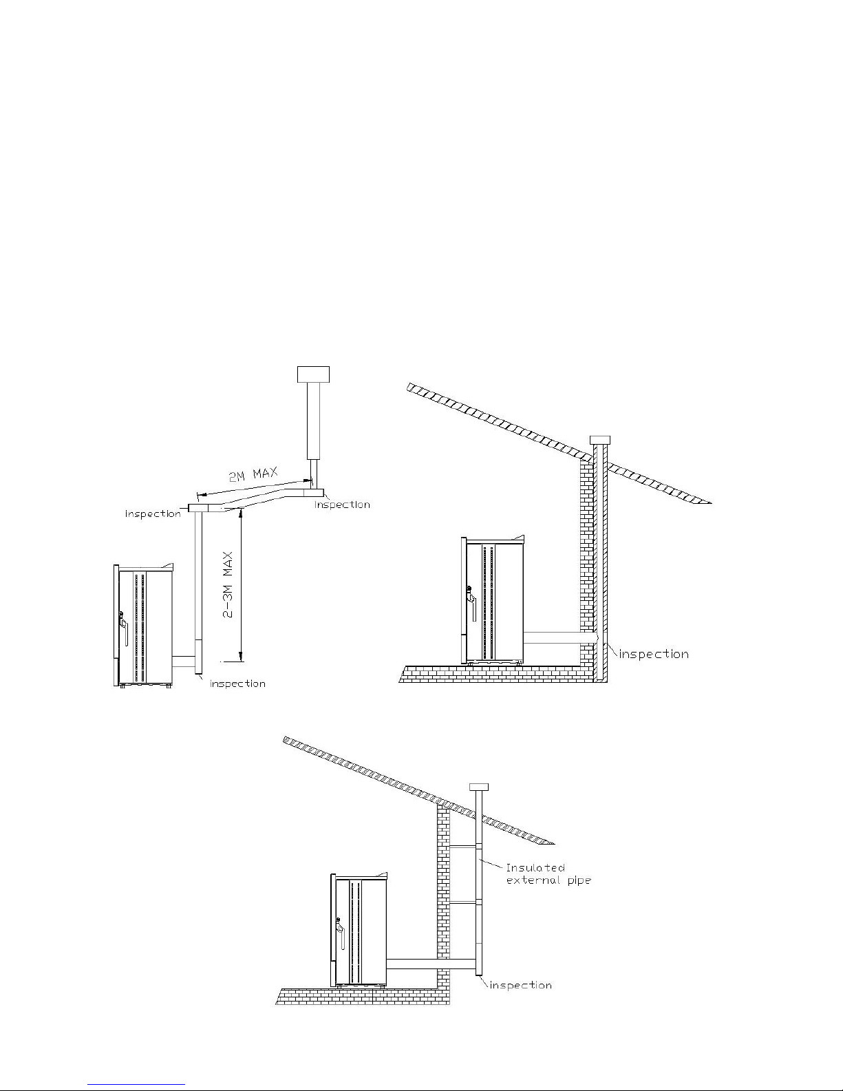
The following figures are on optimal method to ensure smoke exhausting. The back part of Pellet Stove must
be descended min 1.5m to the external end of building to ensure the residual smoke can be discharged. (Or the
smoke may be blocked in the combustion room and cause pollution). The user must allow the exhaust smoke
through the roof via air exhausting pipe (a chimney), the following figures will list you some optimal solutions.
Don’t forget to embed a plug at T location to fix the smoke channel at proper height and resist bad weather
through roof and smoke channel pipeline.
If the smoke pipe is too wide, we suggest you to insert a steel pipe or stainless steel pipe with less than 150mm
diameter. Paint with small amount at the inlet and outlet of smoke exhausting pipe. Mesh materials are
prohibited to be set at the end of exhausting pipe, because it may damage the functions of Pellet Stove. If the
smoke pipe is not installed in fix method, it shall open the pipe for inspection and possible cleaning the
transverse section in it. Operate according to the Figures. Above description is to make the combustion
materials and ash be stored in a certain place during discharging process. When the Pellet Stove is operated in
Page 31
30
low pressure combustion room, it will cause a slight pressure when the smoke is discharged from the smoke
channel. To ensure the smoke exhausting system, e.g. steep pipe, is sealed and normal, it shall use red silicone
to seal all connection points (which can bear 350 ℃). Pipeline coating shall use insulation materials (rock,
clay fibbers), or it can also use the insulated piping system, so that internal part of the exhausting pipe can be
checked and cleaned. A smoke exhausting system shall be installed separately for the Pellet Stove. If by any
change, the Pellet Stove is not connected with smoke exhausting system normally, it is likely to lower the
running speed of Pellet Stove and cause extreme overheating phenomena at the same time. In some cases of
partial damages, it may be able to be changed safely. If sideway pipeline is used to exhaust smoke, the user
shall pay attention not to use silicon top connect pipe with pressure.
Fig 36 Fig 37
Fig 38
Page 32

31
12 Technical advice
12.1 Installation and Operation Suggestions
1 Never disconnect power supply. If the power is disconnected, it may cause smoke leaking into the room, which
is very dangerous. Meanwhile, the machine cannot be turned off and power cannot be shut off.
2 It is prohibited to install the machine separately on the wall. You must ensure the product discharges heat in a
natural way.
3 It is prohibited to install the machine only in accordance with horizontal line. You must consider the wall can
block the air. Therefore, the Pellet Stove will be stopped running under the pressure the exhausted smoke.
4 The machine will reach its max speed after 1 h of running the it to completely dry.
5 It is prohibited to install any gridiron and exhaust pipe that may cause gas ignition.
6 Read the instruction book.
7 Keep the machine clean and tidy. Clean the machine in line with the instruction book.
8 Clean the discharge gas regularly.
9 Use high quality pellet.
10 Make use of exhaust pipe with max length. You can use aluminium coated steel pipe (with 1.5 mm min
thickness) AISI316 stainless steel or 0.5 mm enamelled wire tube.
Vertical min length 4m
Vertical max length 8m
Min 5% slope length 0.5m
Max spacing at least 0.5m
Page 33

32
12.2 Common Problems and Solution
Abnormal Condition
Cause
Solution
Pellet cannot drop into brazier.
Pellet in the container is used up.
Feed wood pellet
Outsourcing materials are existed in the
machine, such as nail, nylon, or small
wood block at the bottom of container.
Clear outsourcing materials
Discharge gas is not discharged smoothly
or it has blocked the smoke channel.
Check discharge gas exhausting to prevent
the smoke channel is blocked.
Exhaust blocking, because the inserted iron
mesh has blocked normal exhausting.
Clean or replace the iron mesh.
Feeding motor does not work.
Replace the feeding motor.
Pellet is collected in brazier during
combustion process.
Discharge gas is not discharged or iron
mesh has blocked normal exhausting.
Clean or replace the iron mesh.
Check discharge gas exhausting to prevent
the smoke channel is blocked.
The brazier is dirty.
Clean the brazier according to the
instructions.
Pellet is accumulated above the brazier.
Clean the brazier often.
Baffle is not placed on proper position.
Place the baffle correctly.
The brazier is higher than its original
position.
Place the baffle correctly.
The Pellet Stove emits smoke.
Wood has been ignited before the machine
is stared.
Make it ignite slowly until it is combusted
completely after 1h.
Smoke exhausting system is not sealed
tightly,
Check whether sealing components are
installed in smoke exhausting system.
If it starts giving off smoke after 25min, the
Pellet Stove is dirty and ignition is quite
slowly.
Clean the Pellet Stove.
The Pellet Stove is cut out after 5 min
during ignition process.
Pellet in the container is used up.
Feed wood pellet
Discharge gas is not discharged smoothly
or it has blocked the smoke channel.
Check discharge gas exhausting to prevent
the smoke channel is blocked.
The Pellet Stove cannot be ignited.
Fuel is consumed up.
Feed wood pellet
Malfunction of igniter
Replace the igniter.
Ventilation air is not out.
Air inlet fan malfunction
Replace or repair air inlet fan
The glass is polluted by thick smoke.
No reason
Clean the glass often.
Baffle is not placed on proper position or
the baffle is lost.
Place the baffle correctly.
Procedure setting cannot be saved.
In the control panel, the battery is
discharging model.
Replace battery.
The Pellet Stove does not give off
heat.
The room is too large.
Make the Pellet Stove be operated with
higher power.
The ceiling is too high or the existence of
staircase causes the heat is scattered to
other rooms.
Make the Pellet Stove be operated with
higher power.
Page 34
33
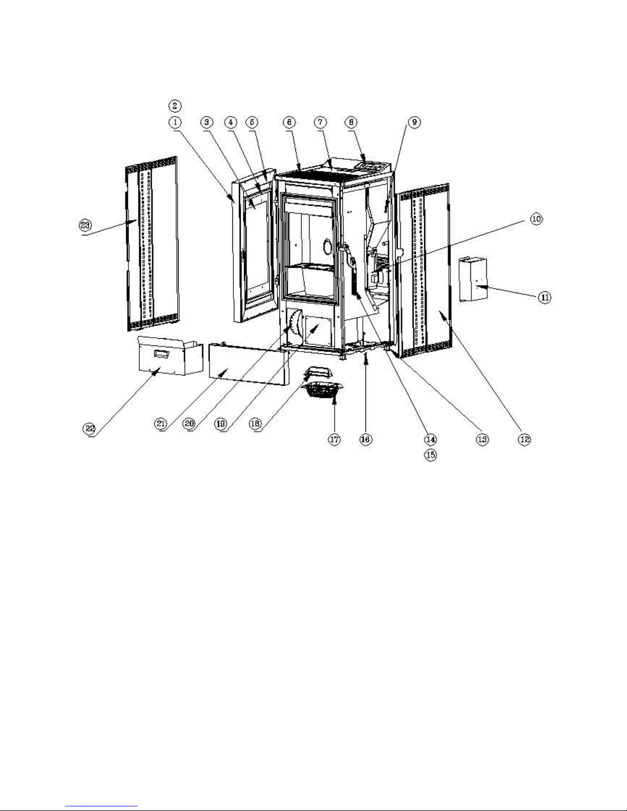
13 Explore Drawing
Page 35

34
23
SL002000095
C065BM00126
Left Panel
1
22
SL002000123
C065BM00143
Ash Pan
1
21
SL002000097
C065BM00128
Below Door
1
20
SL002000164
Smoke Exhaust Fan
1
19
SL002000098
C065BM00129
Below Cover Plate
1
18
SL002000121
C065BM00140
Baffle
1
17
SL002000122
C065BM00141
Brazier
1
16
SL002000174
90 Temperature Switch
1
15
SL002000069
C065BM00118
Handle Assembly
1
14
SL002000133
Silicon Handle
1
13
SL002000135
C065BM00152
Adjusting Foot
4
12
SL002000096
C065BM00127
Right Panel
1
11
SL002000113
C065BM00133
IO Board Protect Shell
1
10
SL002000162
IO Board
1
9
SL002000173
42 Temperature Switch
1
8
SL002000161
Display Board
1
7
SL002000080
C065BM00120
Feeding Door Assembly
1
6
SL002000073
C065BM00119
Top Cover Assembly
1
5
SL002000106
C065BM00131
Inner Door Assembly
1
4
SL002000120
Seal Rope
1
3
SL002000118
C065BM00136
Small Glass
1
2
SL002000119
C065BM00137
Big Glass
1
1
SL002000099
C065BM00130
Front Door Assembly
1
No.
Part No.
Drawing No.
Part Name
Qty
Page 36
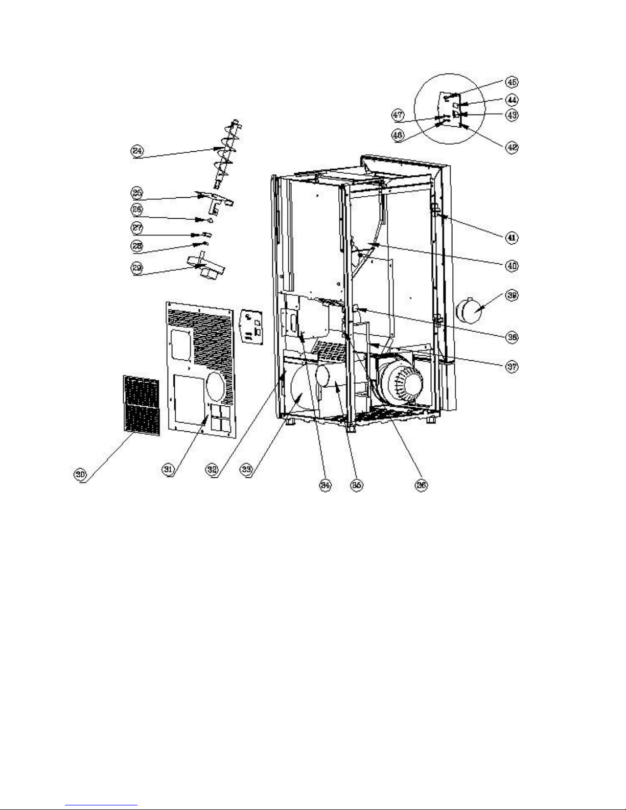
35
Page 37

36
47
SL002000181
Reset Indicator
1
46
SL002000180
Gear Motor Indicator
1
45
SL002000179
Reset Button
1
44
SL002000178
Power Switch
1
43
SL002000177
Power Socket
1
42
SL002000176
Rear Aluminium Panel
1
41
SL002000088
Stainless Steel Hinge
2
40
SL002000047
C065BM00112
Hopper Assembly
1
39
SL002000168
Air Switch
1
38
SL002000171
Ignitor
1
37
SL002000167
Silicon Tube
1
36
SL002000116
C065BM00135
Air Switch Bracket
1
35
SL002000160
C065BM00154
Smoke Fan Frame Assembly
1
34
SL002000114
C065BM00134
IO Board Bracket
1
33
SL002000165
Air Inlet Fan
1
32
SL002000090
C065BM00125
Air Fan Frame Assembly
1
31
SL002000062
C065BM00115
Back Cover Sheet
1
30
SL002000175
C065BM00142
Dustproof Mesh
1
29
SL002000166
Gear Motor
1
28
SL002000039
Inner Six Angel Screw
1
27
SL002000037
C065BM00105
Fixed Ring
1
26
SL002000132
C065BM00145
Rubber Dish
1
25
SL002000034
C065BM00104
Feeding Shaft Bracket
1
24
SL002000030
C065BM00103
Feeding Shaft
1
No.
Part No.
Drawing No.
Part Name
Qty
Page 38

37
SINOLION LIMITED
Address: 1908,19th Floor St Georges Building, 2 Ice House Street, Central, Hong Kong
EUROPE DISTRIBUTOR:
ECOHEAT S.L.
Plaça Gal·la Placidia 1-3, esc. B 11è 2a
08006 Barcelona , SPAIN
 Loading...