

Page 1

SingMai Electronics
SM08
User Manual Revision 0.
2
Page1of
36
SM08
Advanced Composite Video Interface:
aCVi to HD-SDI converter
module
User Manual
Revision 0.2
23rdJuly 2016
Page 2

SingMai Electronics
SM08
User Manual Revision 0.
2
Page2of
36
Revision History
Date Revisions Version
11-07-2016 First Draft. 0.1
23-07-2016 Added chapter on the test points.
Added comment on the Quartus version.
Added 720p/25Hz-30Hz standards to aCVi
description.
Specifications updated.
0.2
Page 3

SingMai Electronics
SM08
User Manual Revision 0.
2
Page3of
36
Contents
Revision History....................................................................................................................................... 2
Contents................................................................................................................................................... 3
Tables ....................................................................................................................................................... 3
Figures......................................................................................................................................................3
1. Introduction ...................................................................................................................................5
2. Connecting up the module ............................................................................................................6
3. aCVi Overview ................................................................................................................................8
4. Circuit description ........................................................................................................................ 10
5. Re-programming the FPGA ..........................................................................................................21
6. Test Point Monitoring.................................................................................................................. 23
7. Specification................................................................................................................................. 25
Appendix A: PCB Overlay ......................................................................................................................30
Appendix B: Bill of Materials................................................................................................................. 32
Appendix C: AC-DC adaptor .................................................................................................................. 35
Tables
Table 1 Video standard selection. ...........................................................................................................6
Table 2 aCVi supported video formats. ..................................................................................................8
Table 3 PT51 and ADC sample rates. ..................................................................................................... 10
Table 4 SM08 Bill of Materials. .............................................................................................................34
Figures
Figure 1 SM08 module............................................................................................................................. 5
Figure 2 SM08 Component positions. ....................................................................................................6
Figure 3 SM06 Switches (Switches 1-5 shown ON)................................................................................ 7
Figure 4 aCVi Spectrum. ..........................................................................................................................9
Figure 5 SM08 schematics - sheet 1. ......................................................................................................12
Figure 6 SM08 schematics - sheet 2. .....................................................................................................13
Figure 7 SM08 schematics - sheet 3...................................................................................................... 14
Figure 8 SM08 schematics - sheet 4. .....................................................................................................15
Figure 9 SM08 schematics - sheet 5. .................................................................................................... 16
Figure 10 SM08 schematics - sheet 6.....................................................................................................17
Figure 11 SM08 schematics - sheet 7. .................................................................................................... 18
Figure 12 SM08 schematics - sheet 8. ................................................................................................... 19
Figure 13 SM08 schematics - sheet 9. ................................................................................................... 20
Figure 14 Re-programming the SM08....................................................................................................21
Figure 15 Quartus FPGA programmer................................................................................................... 22
Figure 16 SM08 Test point location. ..................................................................................................... 23
Figure 17 Horizontal sync test output................................................................................................... 23
Figure 18 Vertical sync test output. ...................................................................................................... 24
Figure 19 NTSC 75% colour bars - waveform. ........................................................................................ 25
Figure 20 NTSC 75% colour bars - vectors. ............................................................................................26
Figure 21 NTSC - SDI status display. ......................................................................................................26
Figure 22 PAL 75% colour bars - waveform. .......................................................................................... 27
Figure 23 PAL 75% colour bars - vectors................................................................................................ 27
Figure 24 PAL 75% colour bars - lightning. ............................................................................................28
Figure 25 PAL - CCIR17 waveform. ........................................................................................................ 28
Figure 26 PAL - 2T pulse......................................................................................................................... 29
Page 4

SingMai Electronics
SM08
User Manual Revision 0.
2
Page4of
36
Figure 27 PAL - 5.75MHz frequency sweep. ......................................................................................... 29
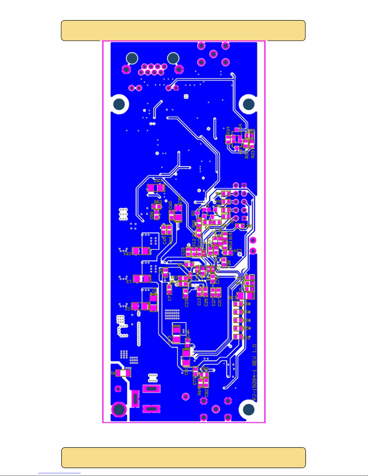
Figure 28 SM08 PCB overlay - top side. ................................................................................................30
Figure 29 SM08 PCB overlay - bottom side. ..........................................................................................31
Figure 30 AC-DC adaptor specification- Page 1. ...................................................................................35
Figure 31 AC-DC adaptor specification- Page 2. ....................................................................................36
Page 5
SingMai Electronics
SM08
User Manual Revision 0.
2
Page5of
36
1. Introduction
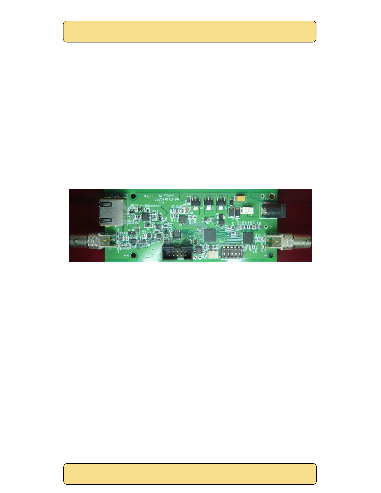
SM08 is a receiver module compatible with the aCVi Advanced Composite Video Interface format,
and also with NTSC/PAL and 960H standards. SM08 accepts analogue aCVi encoded video (and
NTSC/PAL) which it decodes and formats to an HD-SDI (or SDI) output.
aCVi is a method to transmit HD video over long distances of existing coaxial or twisted-pair cable
networks or allow the use of less expensive RG-59/UTP cable in long distance installations.
SM08 can accept either twisted pair or coaxial cable inputs (build option) and supports the
following HD aCVi formats: 720p-25/30/50/59/60Hz, 1080p-24/25/29/30Hz, 1080i-50/59/60Hz as well
as NTSC-M/PAL and NTSC-960H and PAL-960H video standards. Switching between SD and HD
formats is manual, but switching between the various HD aCVi formats and between NTSC/PAL is
automatic.
The module is also compatible with the aCVI bidirectional data interface.
Figure 1 SM08 module.
Page 6
SingMai Electronics
SM08
User Manual Revision 0.
2
Page6of
36
2. Connecting up the module
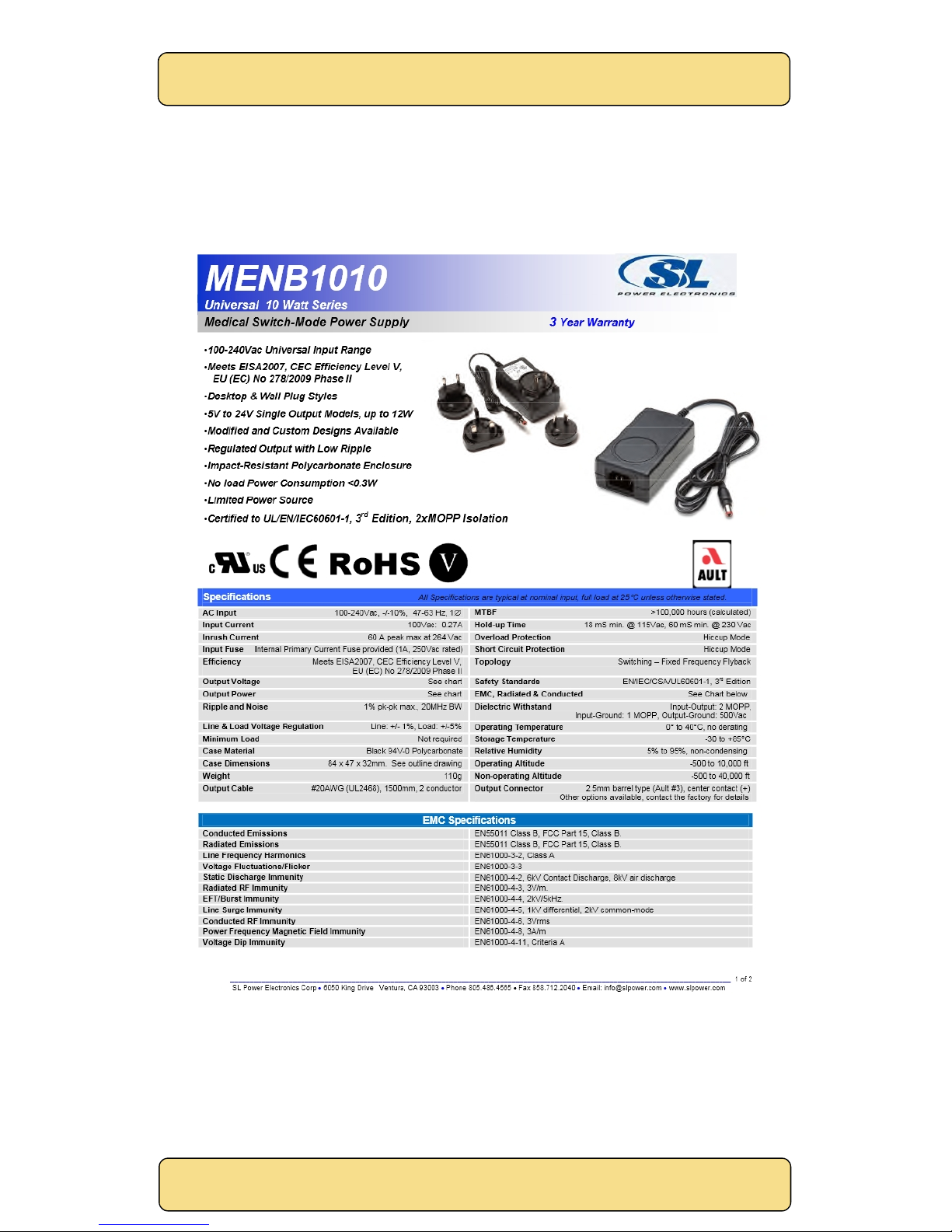
The SM08 module is powered by a universal input (90-260VAC) AC-DC adaptor. The 5VDC output
of this adaptor should be connected to the jack input of the SM08. The specification of the AC-DC
power adaptor can be found in Appendix C.
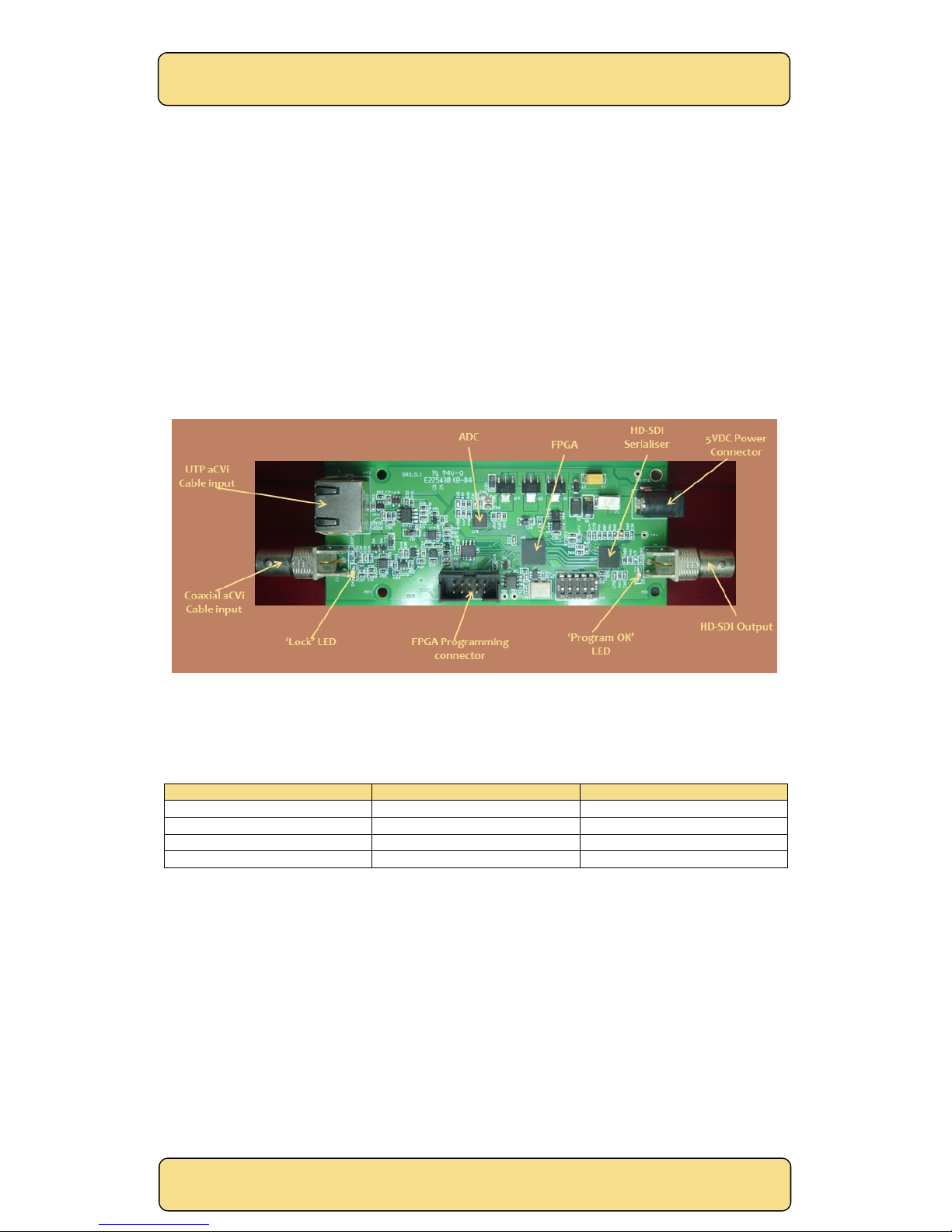
Once connected, the green LED, ‘Program OK’, should light, indicating the FPGA has been
correctly programmed. See Figure 2.
SM08 can accept either coaxial or twisted pair cable inputs, but this is a build option for the board
and needs to be specified at the time of order.
The analogue CVBS input should be applied to the appropriate connector. The HD-SDI output
should be connected to a compatible monitor or waveform monitor. (Note: some aCVi supported
standards, such as 720p/25Hz and 720p/30Hz, may not be accepted by all HD-SDI receivers.)
Figure 2 SM08 Component positions.
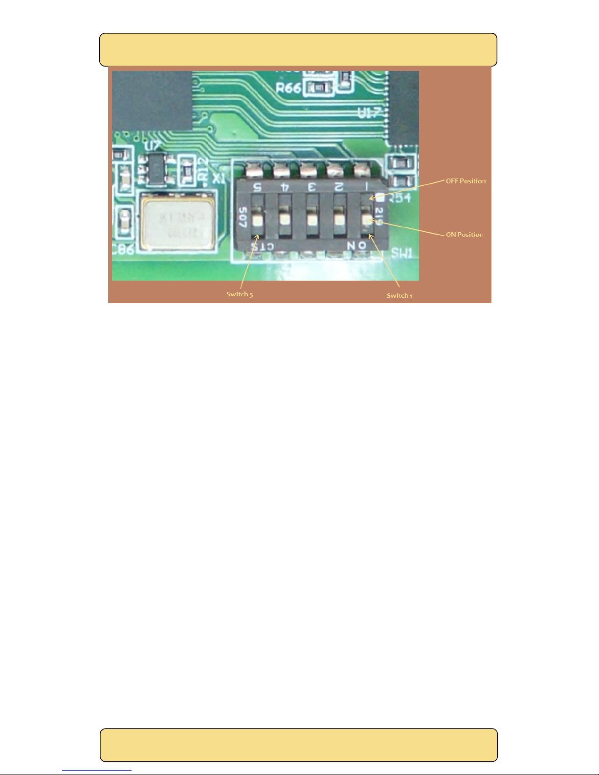
SM08 can accept aCVI, NTSC-M/PAL or NTSC-960H/PAL-960H formats. Switching between these
various formats is manual, using switches as shown in Figure 3 and Table 1.
Switch 2 Switch 1 Format
ON ON aCVI HD
ON OFF NTSC-M/PAL
OFF ON aCVi HD
OFF OFF NTSC-960H/PAL-960H
Table 1 Video standard selection.
Within each group of standards the video standard selection is automatic. For example, if aCVi is
selected, the PT51 decoder will automatically select between 720p-25/30/50/59/60Hz, 1080p24/25/29/30Hz and 1080i-50/59/60Hz standards. If the video input is one of the standards within
the selected group and within the range of the horizontal phase locked loop, the ‘Lock’ LED will
light.
Page 7
SingMai Electronics
SM08
User Manual Revision 0.
2
Page7of
36
Figure 3 SM06 Switches (Switches 1-5 shown ON).
Page 8
SingMai Electronics
SM08
User Manual Revision 0.
2
Page8of
36
3. aCVi Overview
The following is a brief overview of the aCVi interface.
The basic concept of the aCVi interface is to build on the proven and reliable transport method of
NTSC, (the advantages of PAL – v.v. multi-path reception – is not relevant to a cable system so
NTSC is used as the model). NTSC transmissions are capable of transmitting more than 1km across
RG-59 cable but the bandwidth is limited to 5MHz. Because the cable system is a closed system, it
is only necessary for the transmitter and receiver to ‘understand’ each other and we can modify
the basic NTSC method to suit HD transmissions.
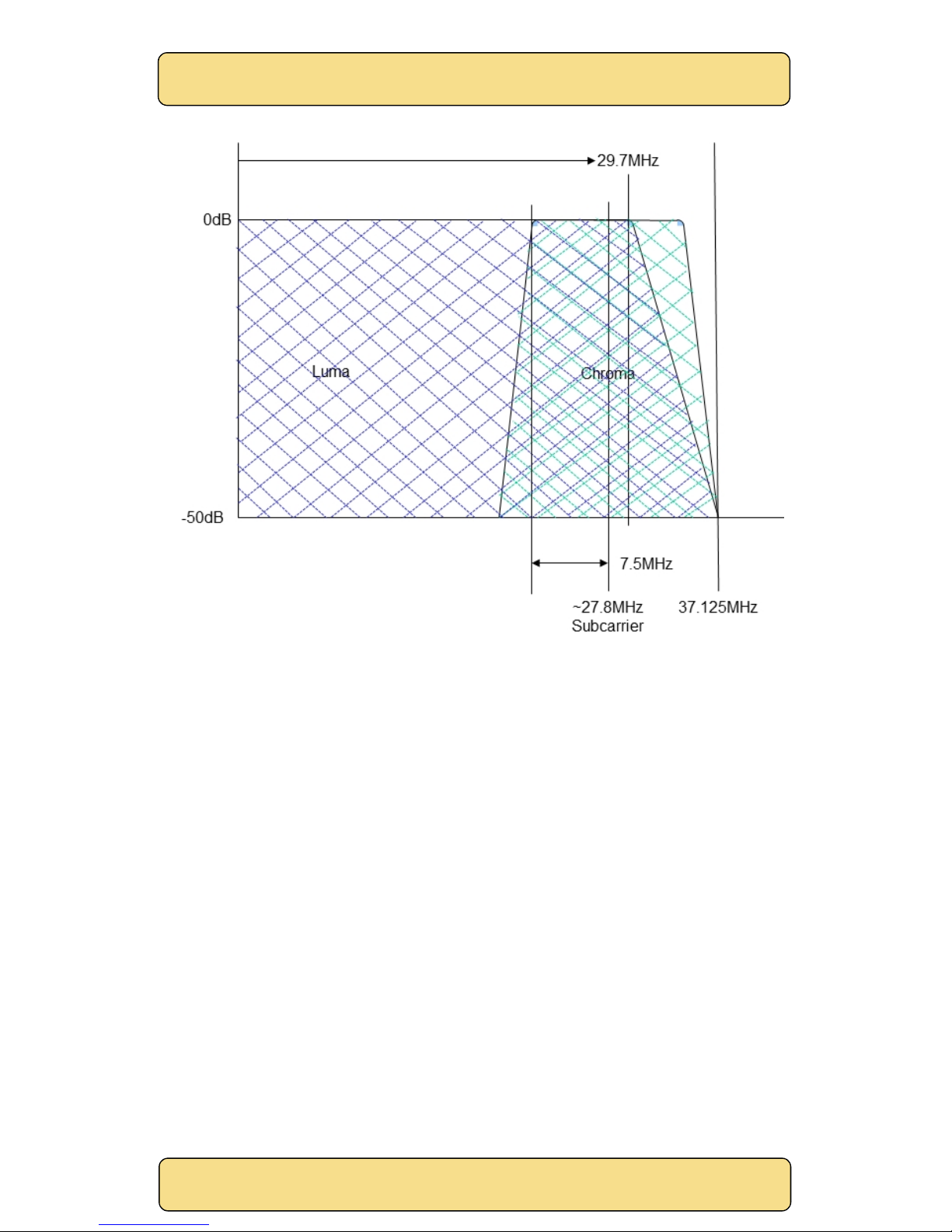
According to the SMPTE-296M specification, HD (74.25MHz sampling) video transmission requires
a luma bandwidth of 30MHz and chroma bandwidth of 15MHz. To save on system costs aCVi
supports the 30MHz luma bandwidth but constrains the chroma bandwidth to 7.5MHz (4:1:1
sampling).
The colour difference signals are modulated onto a carrier in quadrature so they effectively use
the same bandwidth: the chroma subcarrier is ~27.8MHz.. The high frequency luma and the
modulated chroma overlap above 18.6MHz but because of the line to line phase relationship of the
chroma, may be separated using a luine comb filter (and also because of the use of single chip
image sensors, there is usually little high frequency content to cause image artifacts).
The effective bandwidth of the complete signal is therefore approximately 9.3MHz (chroma upper
sideband + filter roll off) + 27.8MHz or about 37MHz, setting a minimum sampling frequency of 2 x
37MHz or 74MHz. For convenience we choose 74.25MHz as a sampling frequency as this is related
to the SMPTE272M standard; (see Figure 4).
For transmission over 300m of RG-59 cable we can expect 18dB loss at higher frequencies
(6.2dB/100m @ 50MHz). However the synchronizing signals are at a much lower frequency where
the loss is only about 1-2dB so reliable rastering of the received signal should always be assured.
The peak to peak video level of aCVi is 1.26V (100% colour bars) which maintains compatibility with
any legacy SD equipment on the network and also allows common low-power 3.3V drivers to be
used.
Table 2 lists the currently supported video formats for aCVi.
Format Pixels/line Line frequency FSC/FHratio Subcarrier
720p/25 3960 18.75kHz 1482.5 27.796875MHz
720p/30 3300 22.5kHz 1235.5 27.79875MHz
720p/50Hz 1980 37.500kHz 741.5 27.80625MHz
720p/59.94Hz
1
1650 44.955kHz 618.5 27.804695MHz
720p/60Hz 1650 45.000kHz 617.5 27.7875MHz
1080p/24Hz 2750 27.0kHz 1029.5 27.7965MHz
1080p/25Hz 2640 28.125kHz 988.5 27.8015625MHz
1080p/29.97Hz
1
2200 33.716kHz 824.5 27.7990759MHz
1080p/30Hz 2200 33.750kHz 823.5 27.793125MHz
1080i/50Hz 2640 28.125kHz 988.5 27.8015625MHz
1080i/59.94Hz
1
2200 33.716kHz 824.5 27.7990759MHz
1080i/60Hz 2200 33.750kHz 823.5 27.793125MHz
Table 2 aCVi supported video formats.
1
Input clock is 148.3516484MHz (else 148.5MHz).
Page 9
SingMai Electronics
SM08
User Manual Revision 0.
2
Page9of
36
Figure 4 aCVi Spectrum.
Page 10

SingMai Electronics
SM08
User Manual Revision 0.
2
Page10of
36
4. Circuit description
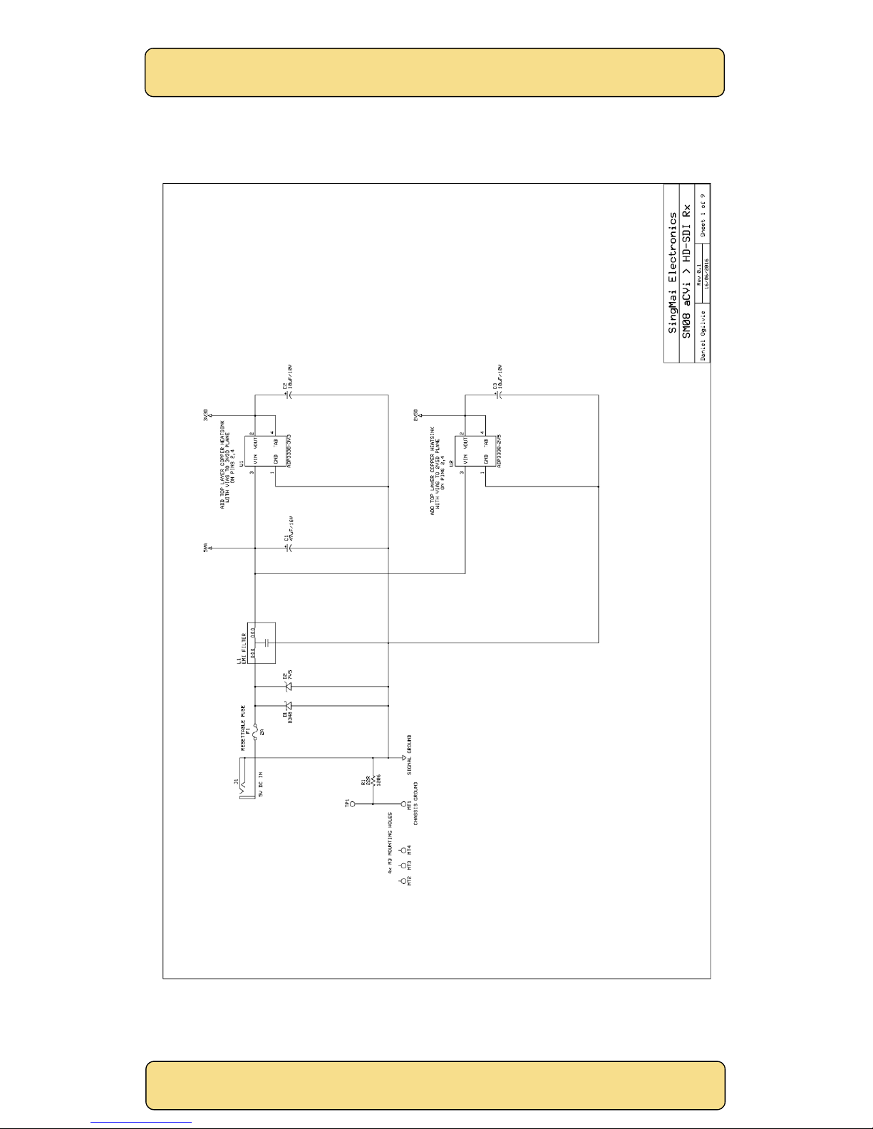
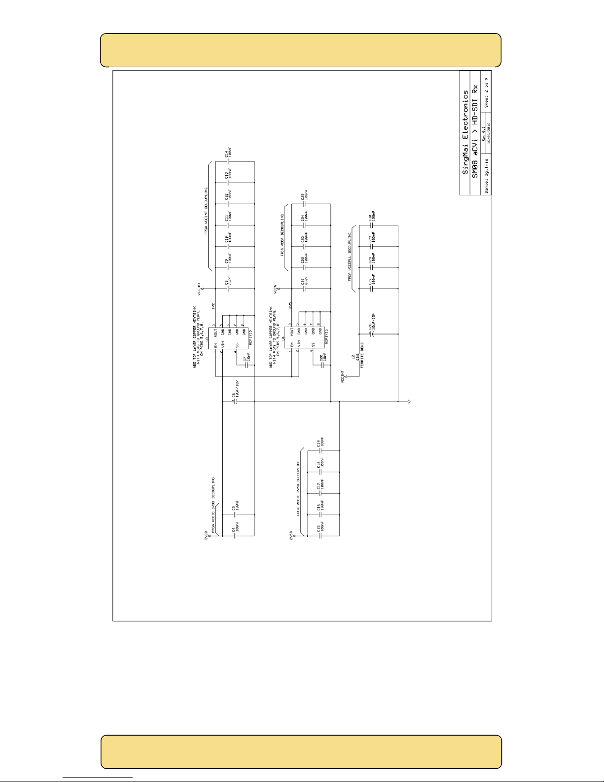
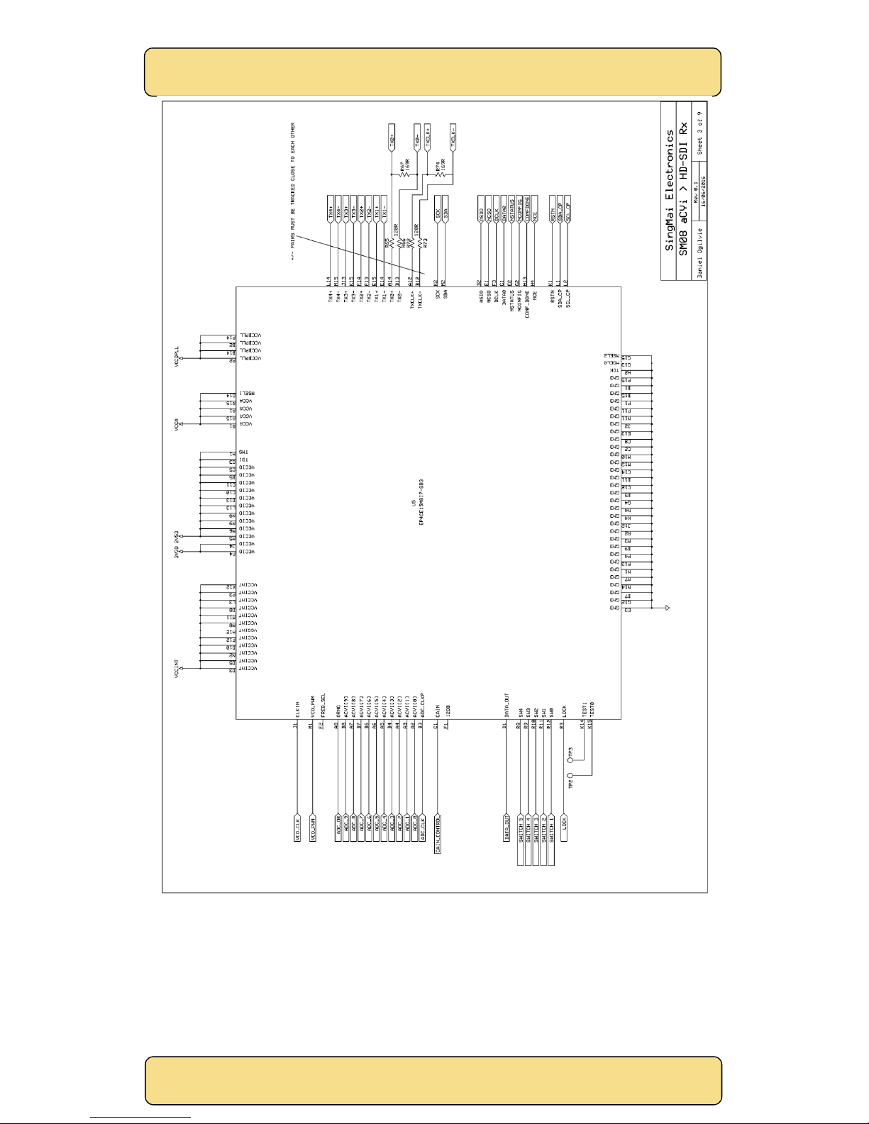
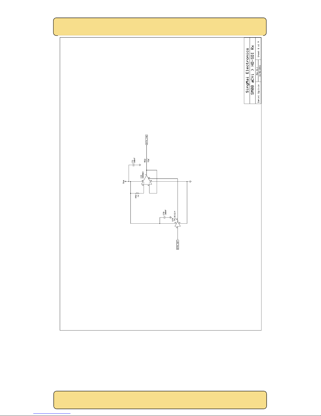
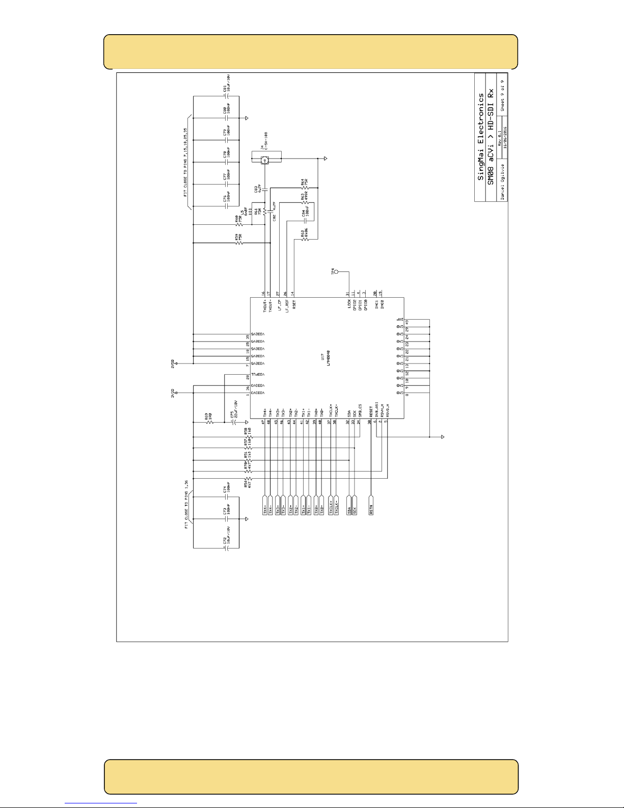
Figures 5-13 show the schematics for the SM08. The component overlay for the PCB is shown in
Appendix A.
Below is a brief technical description of the SM08 module.
Sheet 1.
J1 is the 5VDC power input connector to the SM08 module. The 5VDC is protected from overvoltage and reverse polarity inputs by D1, D2 and resettable fuse, F1. The input is then filtered by L1
and C1 to provide the ‘clean’ 5VDC for the analogue input stage and also linear regulated by U1 and
U2 to provide the 3.3VDC and 2.5VDC supply voltages.
Sheet 2.
U3 provides the 1.2VDC for the internal voltage of the FPGA. U4 provides the 2.5VDC for the
analogue PLL circuity of the FPGA and L2 and C26 filter the VCCINT for the FPGA PLL digital blocks.
C4-C30 provides local decoupling for the FPGA.
Sheet 3.
Sheet 3 is the FPGA. The FPGA is an Altera EP4CE15 device in a MBGA 164 pin 0.5mm pitch package.
The FPGA contains the PT51 aCVi/NTSC/PAL decoder, a SingMai PT13 control microprocessor, and
the HD-SDI/SDI formatting.
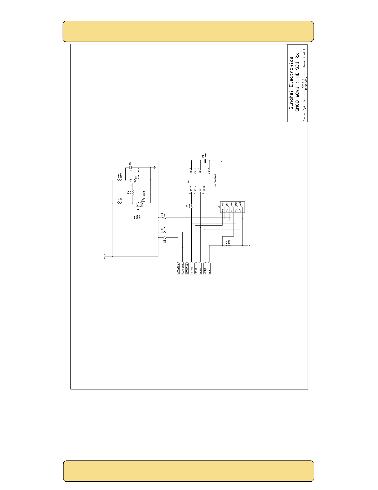
Sheet 4.
The FPGA is a volatile device and needs programming on switch on, which it does using U6, a 4Mb
EEPROM. The device is automatically configured on switch on, and successful configuration is
indicated by D3 LED (‘Program OK’). The EEPROM may also be reprogrammed via J2, which is
compatible with the Altera ‘USB-Blaster’ and the Quartus Programmer (see Chapter 5).
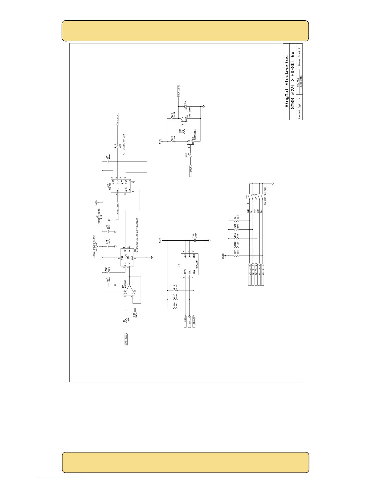
Sheet 5.
The PT51 decoder requires a line locked clock (see PT51 user manual, chapter 6). To achieve this a
voltage controlled crystal oscillator is used, with the frequency of the oscillator controlled using a
PWM output from the PT51 IP core. This output, VCO_PWM, is filtered by R11 and C32 to provide an
analogue voltage which is buffered by U7. This 0-3.3V control voltage adjusts the frequency of the
crystal voltage controlled oscillator (VCXO), X1. The adjustment range is approximately ±150ppm.
The centre frequency (1.65VDC control voltage) is 27.0MHz. Note, this adjustment range may not
be sufficient for some NTSC/PAL inputs and horizontal phase lock may not be achieved with
these video sources. However a wider range (non-crystal) VCO will not achieve the jitter
specification of the HD-SDI/SDI output.
The output of the VCXO is then multiplied to 74.25MHz or 74.18MHz (to provide support for
29.97/59.94Hz formats) – selection is performed via the FREQ_SEL port. VCO_CLK is the clock
input to the FPGA.
The VCO_CLK input is fed to an FPGA PLL. This PLL is dynamically configured depending on the
selected video standards (aCVi, NTSC/PAL or 960H). The output of the PLL provides 3 clocks as
shown in Table 2.
Clock NTSC/PAL NTSC-960/PAL-960H aCVi
ADC clock 27MHz 36MHz 74.25MHz
1
PT51 Clock 13.5MHz 18MHz 74.25MHz
1
PT51 Clock2x 27MHz 36MHz 148.5MHz
2
Table 3 PT51 and ADC sample rates.
1
Clock frequency = 74.17582418MHz for 29.97Hz and 59.94Hz field rate standards.
2
Clock frequency = 148.3516484MHz for 29.97Hz and 59.94Hz field rate standards.
Page 11

SingMai Electronics
SM08
User Manual Revision 0.
2
Page11of
36
The ‘Lock’ LED, D4, is driven from a port of the FPGA. It is lit when the PT51 status indicates that
horizontal lock has been achieved and the input is a valid standard supported by the PT51.
Five DIP switches provide standard selection for the SM08 (see Chapter 2) and are read by the
FPGA microprocessor.
U8 is a proprietary copy-protection IC. U8 calculates a checksum from a PT13 generated data
stream, and the calculated checksum from U8 is compared with an FPGA internally generated
checksum. If the two do not match the SM08 module is shut down. This means that even if the bit
stream of the FPGA/EEPROM is captured the PT51 IP core will not run without U8 being fitted.
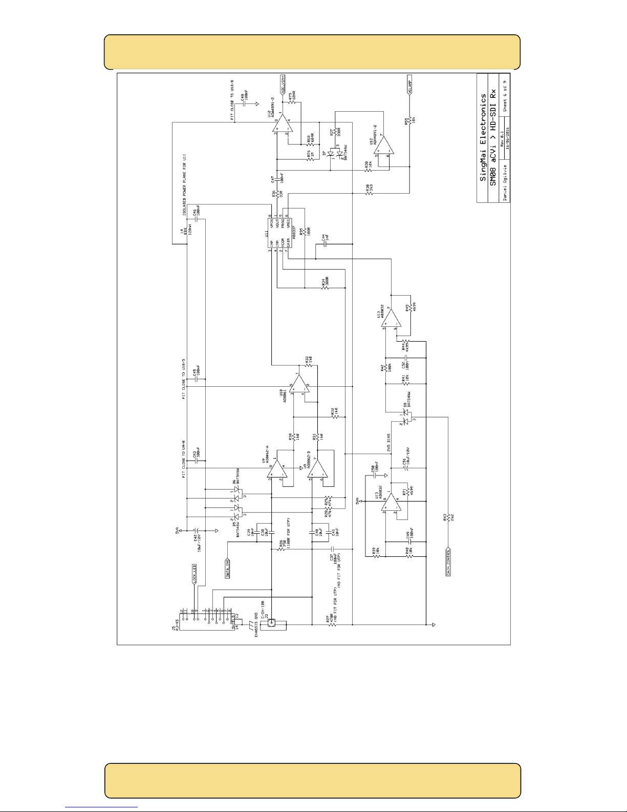
Sheet 6.
Sheet 6 is the analogue front end (AFE). The analogue video inputs, which may be aCVi, NTSC/PAL
or 960H formats, may be either coaxial or twisted pair (build option for the SM08).
If twisted pair, they are terminated in 100Ω (R26) and converted from differential to single ended
outputs by U9 and U10. If coaxial inputs they are treated as a pseudo-differential input, with the
ground screen of the BNC input connector connected to ground via R27 and C37, which affords
some hum rejection for long cable runs.
U13 provides a mid-rail (2.5V) bias voltage with low output impedance as the AFE runs from a
single supply voltage (5V).
U11 is a voltage controlled amplifier. The PT51 decoder provides automatic gain control and the
‘GAIN_CONTROL’ PWM output of the PT51 is used to control the gain of U11. The PWM output is
first clamped to the 2.5V reference voltage to avoid supply variations affecting the gain (D8). R42
and C52 provide low pass filtering of the PWM signal to convert it to an analogue voltage. This is
buffered and amplified by U13 to provide a 0-5V control voltage (although the voltage control
range of U11 is only 2.5V ± 650mV.
The output of U11 is AC coupled into U12A, which is a high input impedance, low input bias current
op-amp. The average DC level of video varies widely and to ensure it can be scaled into the
analogue to digital converter (ADC) properly it must be clamped. The AFE uses a sync tip clamp.
The most negative part of the AC coupled video is clamped to the VCLAMP reference voltage,
which is the most negative voltage reference voltage of the ADC. The ADC requires a 0.5V to 2.5V
(2V pk-pk) input signal and the sync tips (the most negative part of the video signal) are clamped,
using ‘ideal’ diode D7 and U12B, to the 0.5V ADC reference. The black level of the video (back
porch level) is measured and used to restore the video black level by the PT51 decoder.
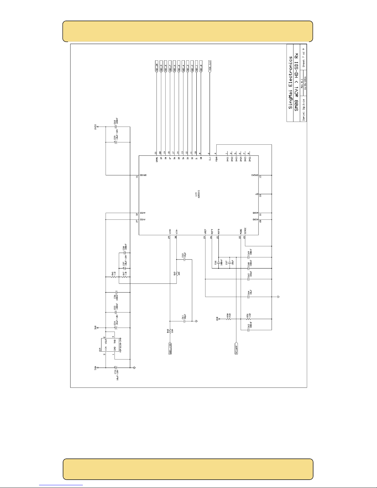
Sheet 7.
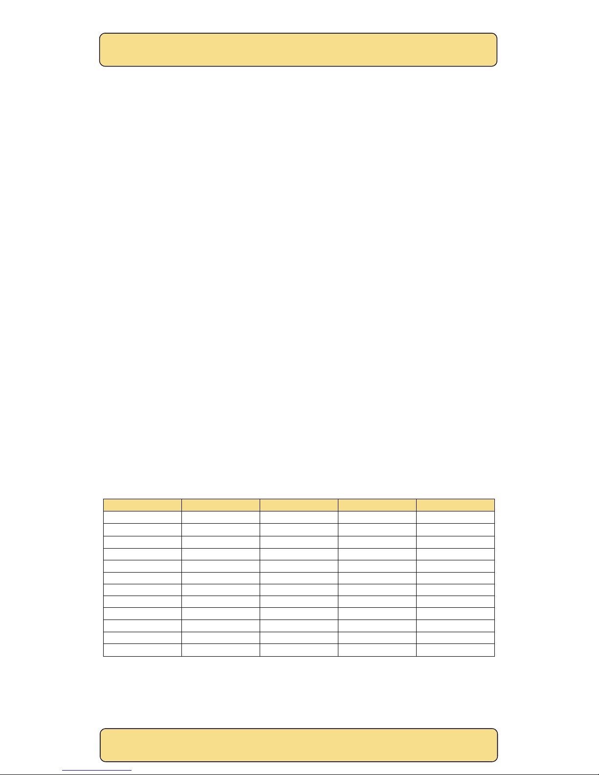
U19 is the ADC, a 10-bit 80MHz component that is clocked at the rate shown in Table 2. The ADC
accepts a differential input, but is used in single-ended mode. The clamped video from U12A is
applied to the VIN+ input, and VIN- input is biased to mid rail (1.5V). U14 provides the ‘clean’ 3.0V
supply for the ADC. The output of the ADC, ADC[9:0] is the straight binary, digital composite video
which is applied directly to the PT51 decoder.
Sheet 8.
The aCVi interface allows bidirectional data to be sent between transmitter and receiver during
dedicated lines of the vertical blanking interval. Data from the transmitter to the receiver is
treated the same as video data, and the ADC ‘data’ line is decoded within the PT51.
Data to be sent from the SM08 to the transmitter is output from the PT51 and FPGA as the
DATA_OUT port. This binary data is converted into a current by U16 and R53 and injected into the
cable input (DATA_INS to AFE input, Sheet 6).
Sheet 9.
The Y, Cb and Cr video and the Hout, Vout and Fout synchronizing signals from the PT51 decoder
are formatted into an HD-SDI/SDI format inside the FPGA. The synchronizing signals are modified
to be compatible with the HD-SDI/SDI Flag requirements and the line count is derived for HD
outputs. The video and the timing signals (TRS) are combined and scrambled according to the HDSDI/SDI specifications and cyclic redundancy check (CRC) is added.
Page 12
SingMai Electronics
SM08
User Manual Revision 0.
2
Page12of
36
The scrambled signal is then multiplexed into 5 data streams at 148.5MHz/27MHz which are driven
as LVDS outputs, together with an LVDS clock, to the HD-SDI/SDI serialiser IC, U17, which converts
these five data signals into one 1.485GHz/270MHz, HD-SDI/SDI compatible, output (J4).
Components L5 and R61 are used to improve the return loss.
Figure 5 SM08 schematics - sheet 1.
Page 13
SingMai Electronics
SM08
User Manual Revision 0.
2
Page13of
36
Figure 6 SM08 schematics - sheet 2.
Page 14
SingMai Electronics
SM08
User Manual Revision 0.
2
Page14of
36
Figure 7 SM08 schematics - sheet 3.
Page 15
SingMai Electronics
SM08
User Manual Revision 0.
2
Page15of
36
Figure 8 SM08 schematics - sheet 4.
Page 16
SingMai Electronics
SM08
User Manual Revision 0.
2
Page16of
36
Figure 9 SM08 schematics - sheet 5.
Page 17
SingMai Electronics
SM08
User Manual Revision 0.
2
Page17of
36
Figure 10 SM08 schematics - sheet 6.
Page 18
SingMai Electronics
SM08
User Manual Revision 0.
2
Page18of
36
Figure 11 SM08 schematics - sheet 7.
Page 19
SingMai Electronics
SM08
User Manual Revision 0.
2
Page19of
36
Figure 12 SM08 schematics - sheet 8.
Page 20
SingMai Electronics
SM08
User Manual Revision 0.
2
Page20of
36
Figure 13 SM08 schematics - sheet 9.
Page 21
SingMai Electronics
SM08
User Manual Revision 0.
2
Page21of
36
5. Re-programming the FPGA
It may be necessary to reprogram the FPGA to demonstrate any customization to the PT51 IP core.
As the SM08 uses an Altera FPGA it is necessary to download the Quartus programmer software
(free from the Altera website: https://wl.altera.com/download/software/prog-software/12.1).
Note, using an older version of the Quartus programmer than 12.1 will result in an programming
error of ‘corrupt POF file’.
Also it is necessary to use the USB-Blaster module, also from Altera (or similar from other
companies): http://www.buyaltera.com/scripts/partsearch.dll?Detail&name=544-1775-ND.
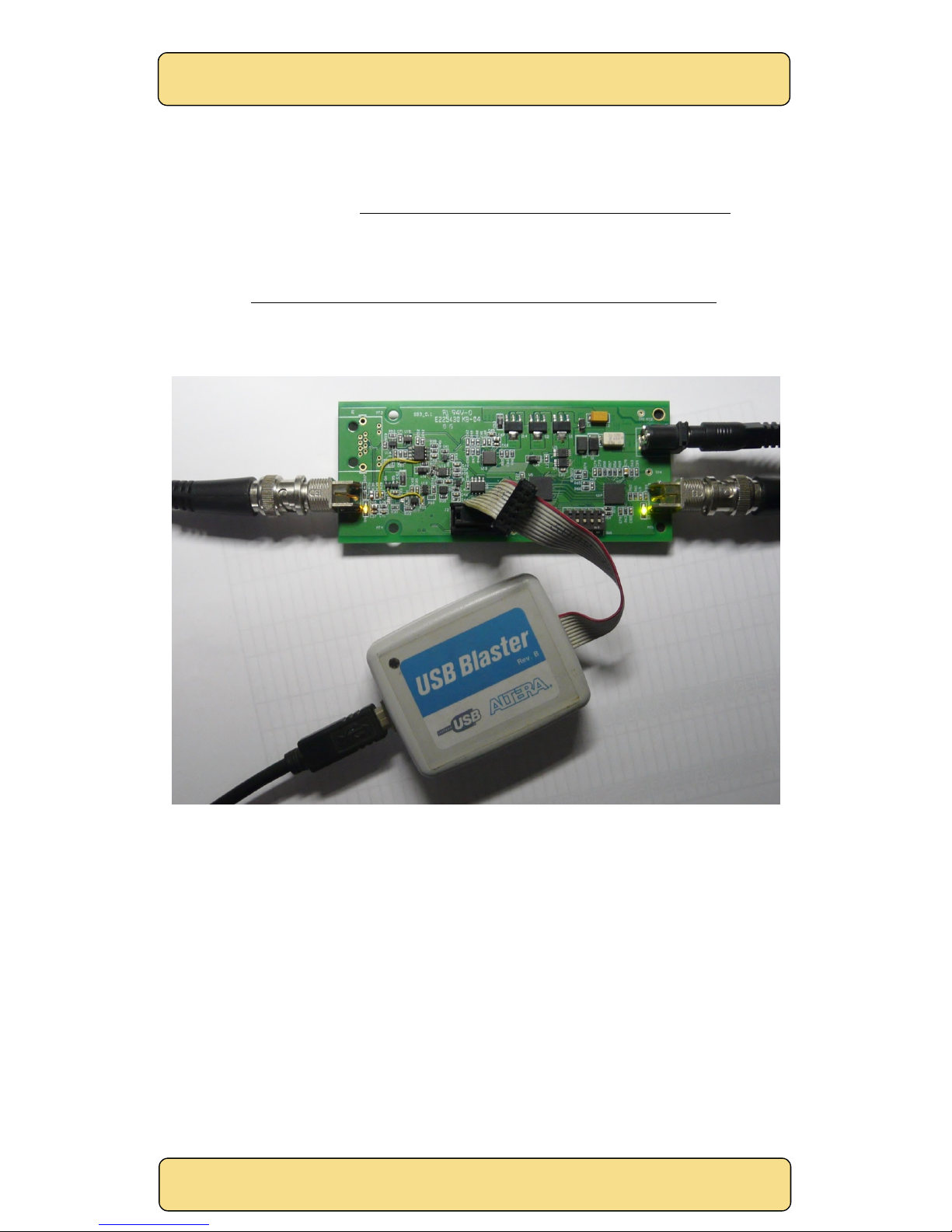
The USB-Blaster 10-way header plugs into J2, the 10W header on the SM06. The header is polarized
to ensure the cable cannot be inserted the wrong way (see Figure 14).
Figure 14 Re-programming the SM08.
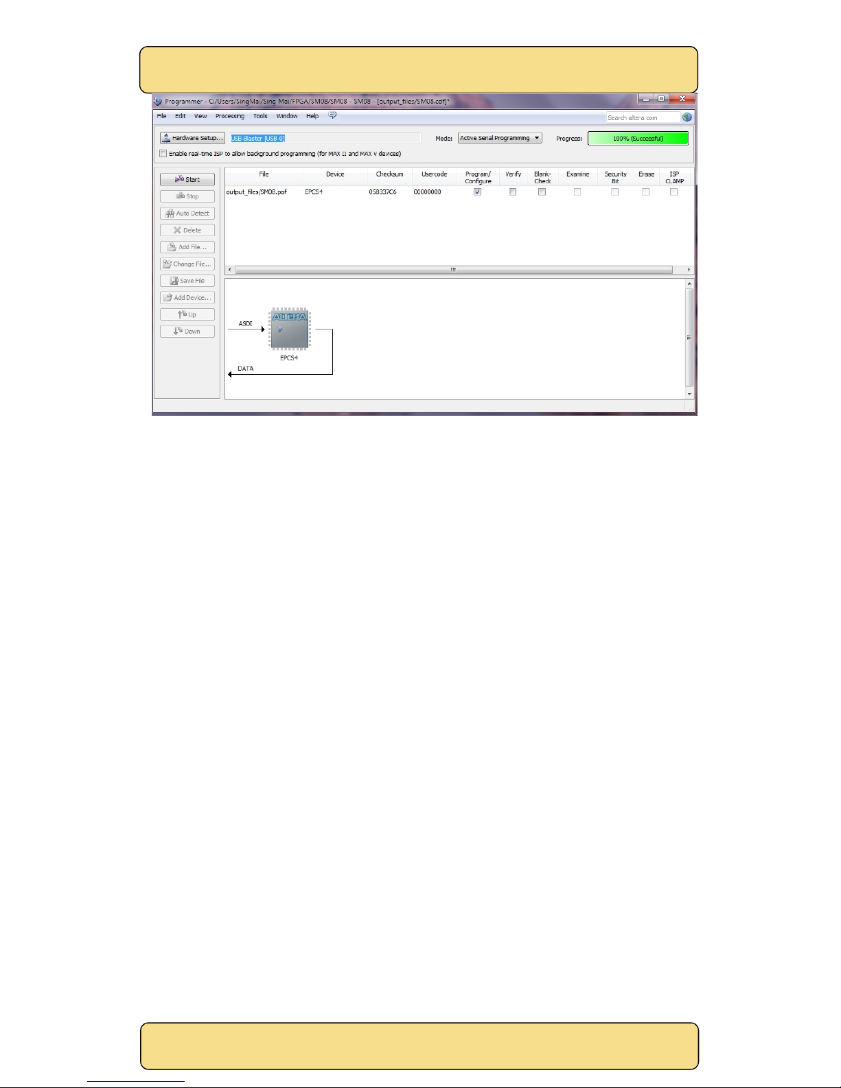
Install and open the Quartus programmer. The screen should look similar to Figure 15.
The new FPGA image will be sent as a file called SM08.pof. Set the programming mode to ‘Active
Serial Programming’. If everything is OK the programmer should recognize the serial EEPROM
(shown as EPCS4). Click the ‘Add File’ button and point to the SM08.pof file. Click the check box
‘Program/Configure’ and click the ‘Start’ button. You should see the progress bar move as the
device is programmed. If successful the bar will show 100% (Successful) after programming is
complete.
After successful programming of the EEPROM, the FPGA will automatically be configured with the
new file and the ‘Program OK’ LED should light.
Page 22
SingMai Electronics
SM08
User Manual Revision 0.
2
Page22of
36
Figure 15 Quartus FPGA programmer.
Page 23
SingMai Electronics
SM08
User Manual Revision 0.
2
Page23of
36
6. Test Point Monitoring
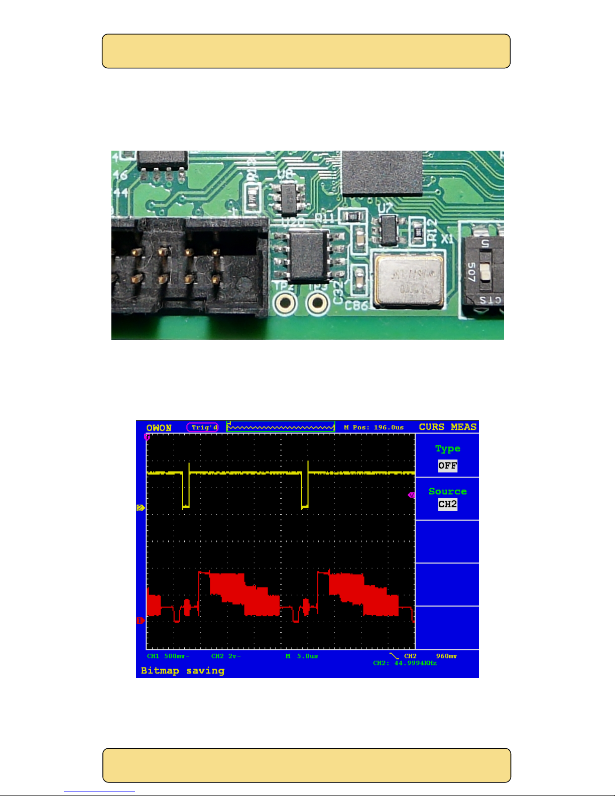
Two test points can be programmed (by SingMai) to provide monitoring of requested points in the
PT51 decoder IP core. The location of the test points, TP2 and TP3, is shown in Figure 16.
Figure 16 SM08 Test point location.
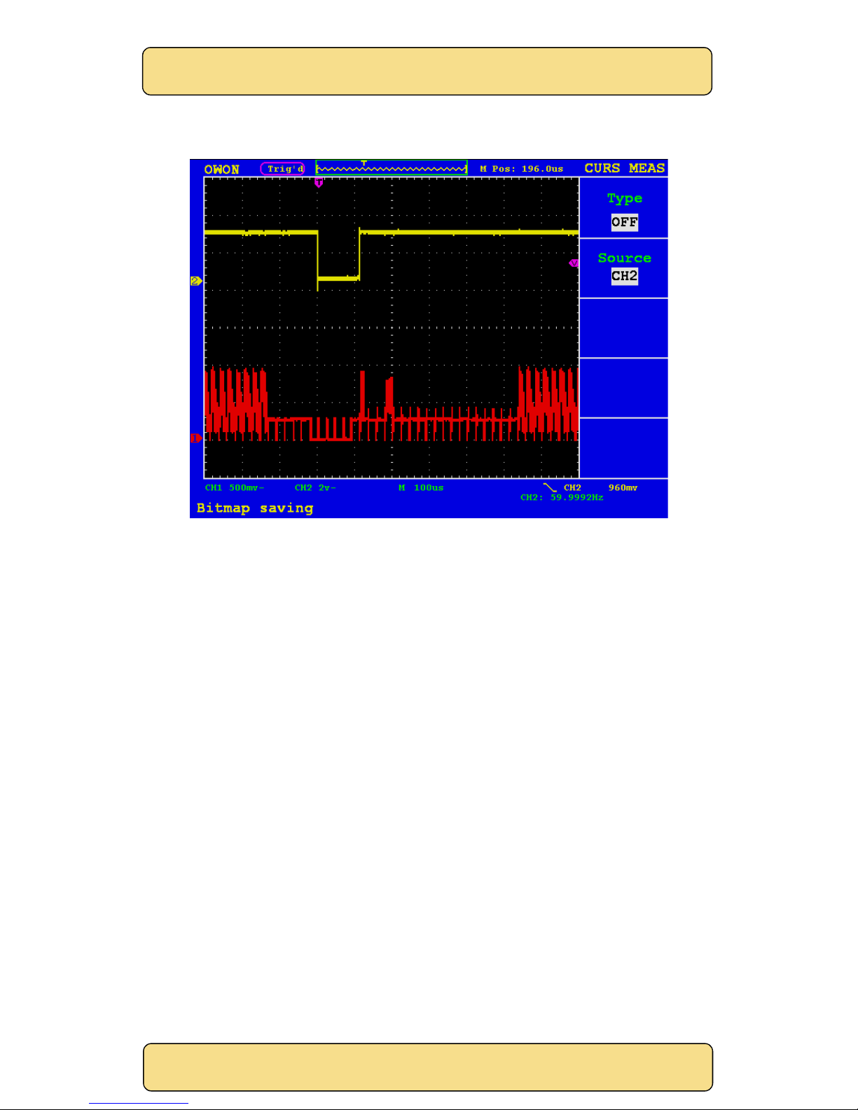
By default they are programmed to monitor the horizontal and vertical sync pulses from the PT51
decoder. Figure 17 shows the horizontal sync output (TP3) and the aCVi input waveform for
720p/60Hz standard and a 75% colour bar test signal.
Figure 17 Horizontal sync test output.
Page 24
SingMai Electronics
SM08
User Manual Revision 0.
2
Page24of
36
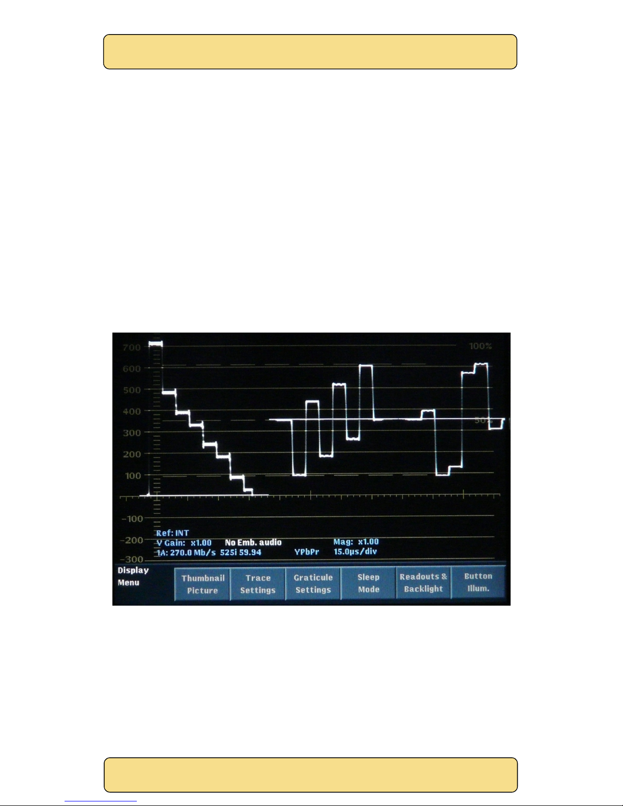
Figure 18 shows the vertical (field) sync output (TP2) and the aCVi input waveform for 720p/60Hz
standard and a 75% colour bar test signal.
Figure 18 Vertical sync test output.
Page 25
SingMai Electronics
SM08
User Manual Revision 0.
2
Page25of
36
7. Specification
The following refers to the specification for the SM08 receiver module only.
Power: +5VDC ± 5% @ ~450mA.
Dimensions: PCB: 120mm x 50mm. Maximum height 19mm (UTP version).
Video standards: aCVi HD: 720p/25Hz,720p/30Hz, 720p/50Hz, 720p/59.94Hz, 720p/60Hz
1080p/24Hz, 1080p/25Hz, 1080p/29.97Hz, 1080p/30Hz, 1080i/50Hz,
1080i/59.94Hz, 1080i/60Hz
SD: NTSC-M, PAL, NTSC-960H and PAL-960H.
Luma bandwidth: aCVi: 29.7MHz ± 1.5dB. >-40dB @ 37.125MHz.
SD: 5.5MHz ± 1.5dB (8MHz ± 1.5dB 960H).
Chroma bandwidth: aCVi: 7.5MHz -3dB. >-40dB @ 9.3MHz.
SD: 1.3MHz -3dB.
Latency: <100µs.
Gain control range: -3 to +20dB.
HD-SDI/SDI output: 20 bit 4:2:2 YCbCr format.
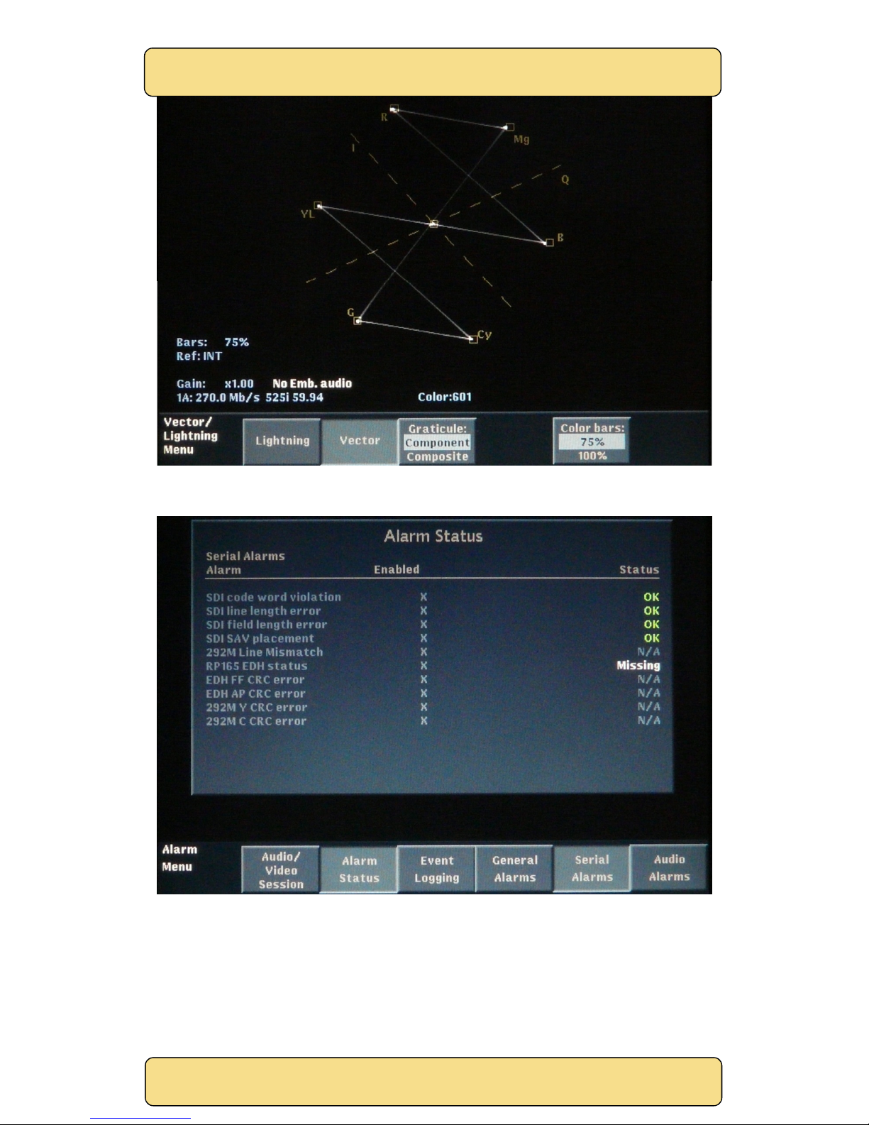
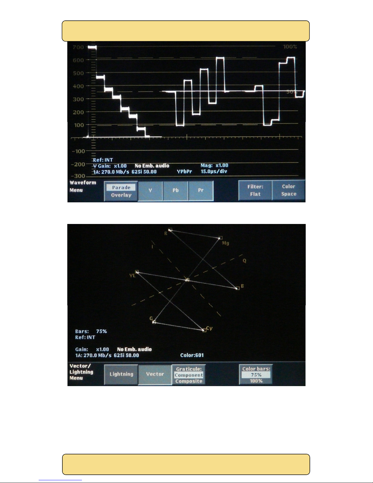
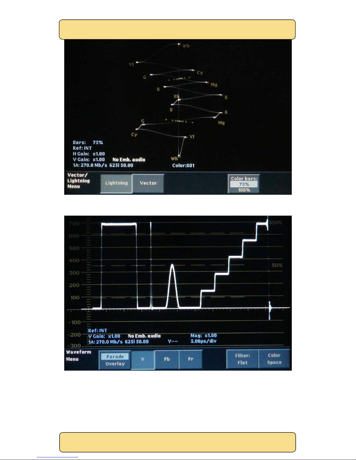
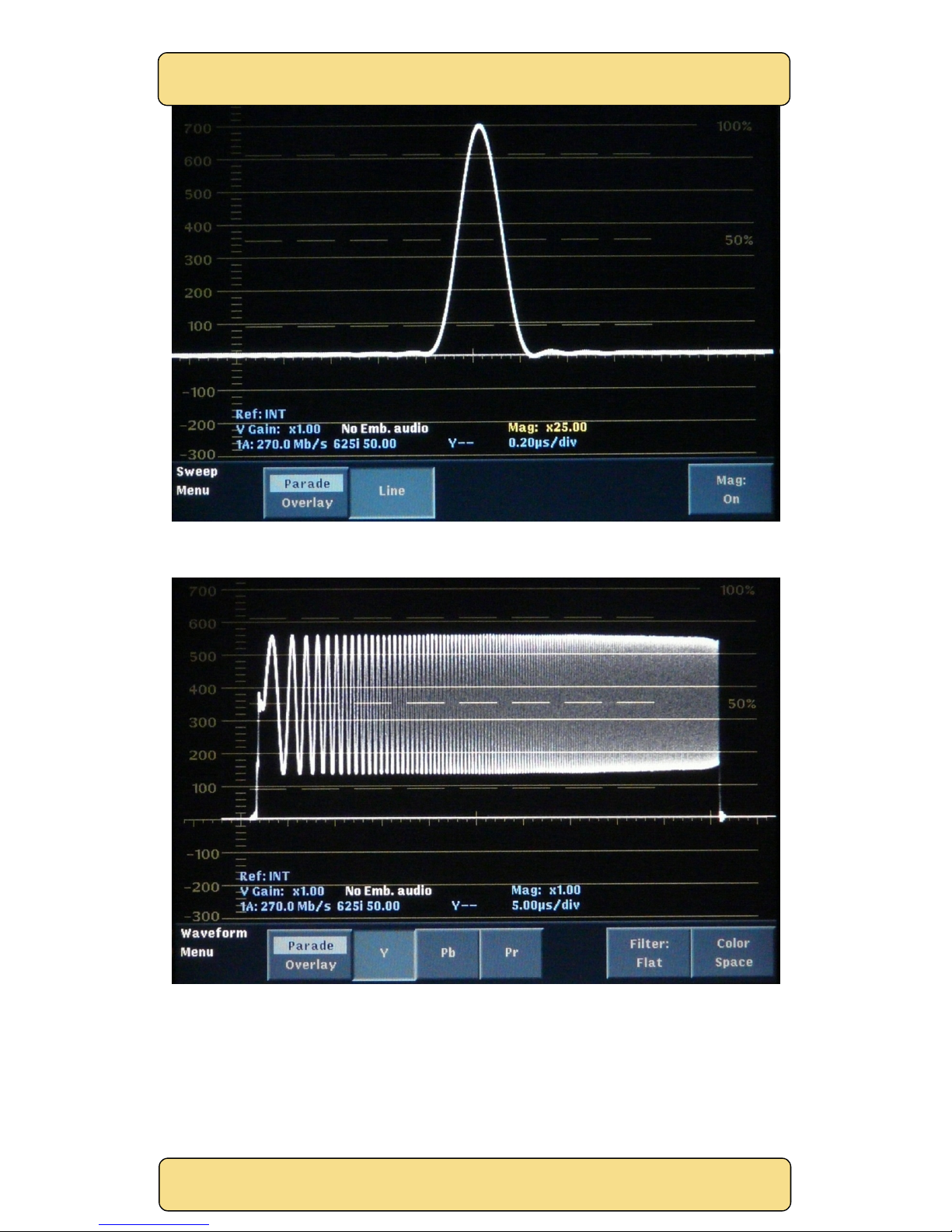
The following measurements were made using a SingMai SM01 video pattern generator, the SM08
evaluation board, and a Tektronix WFM700 SDI waveform monitor.
Figure 19 NTSC 75% colour bars - waveform.
Page 26
SingMai Electronics
SM08
User Manual Revision 0.
2
Page26of
36
Figure 20 NTSC 75% colour bars - vectors.
Figure 21 NTSC - SDI status display.
Page 27
SingMai Electronics
SM08
User Manual Revision 0.
2
Page27of
36
Figure 22 PAL 75% colour bars - waveform.
Figure 23 PAL 75% colour bars - vectors.
Page 28
SingMai Electronics
SM08
User Manual Revision 0.
2
Page28of
36
Figure 24 PAL 75% colour bars - lightning.
Figure 25 PAL - CCIR17 waveform.
Page 29
SingMai Electronics
SM08
User Manual Revision 0.
2
Page29of
36
Figure 26 PAL - 2T pulse.
Figure 27 PAL - 5.75MHz frequency sweep.
Page 30
SingMai Electronics
SM08
User Manual Revision 0.
2
Page30of
36
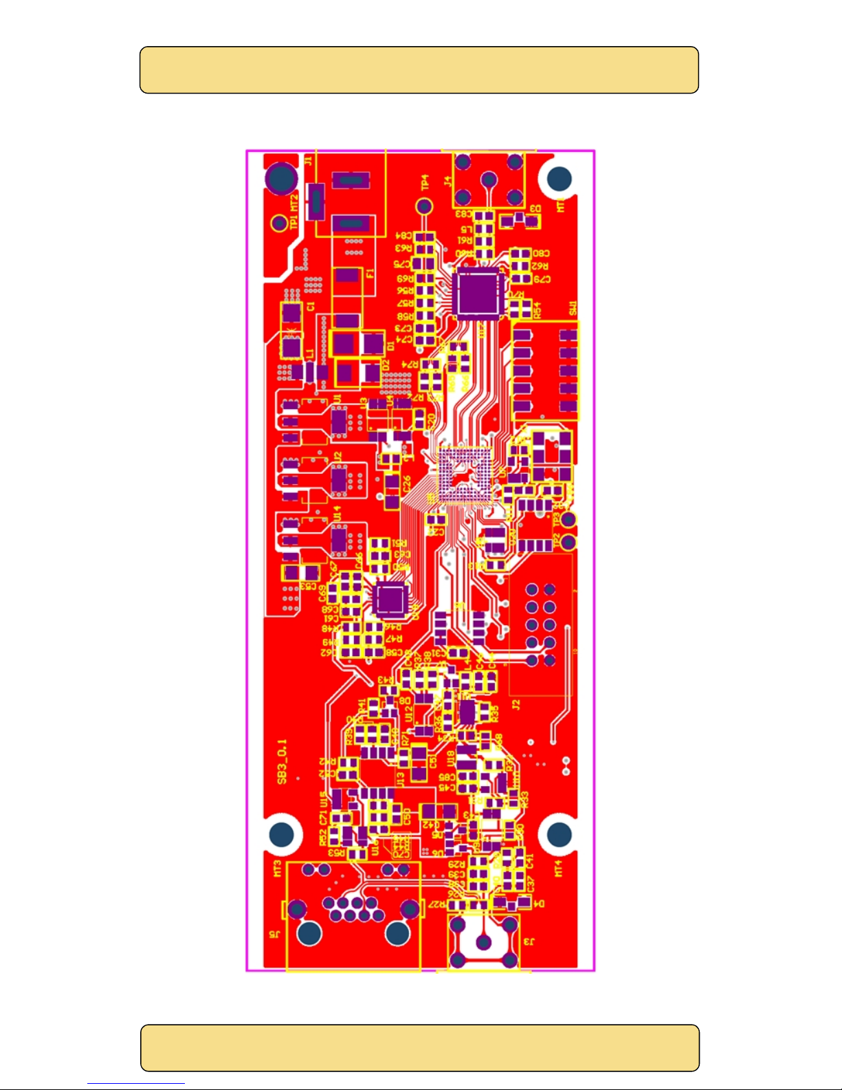
Appendix A: PCB Overlay
Figure 28 SM08 PCB overlay - top side.
Page 31
SingMai Electronics
SM08
User Manual Revision 0.
2
Page31of
36
Figure 29 SM08 PCB overlay - bottom side.
Page 32
SingMai Electronics
SM08
User Manual Revision 0.
2
Page32of
36
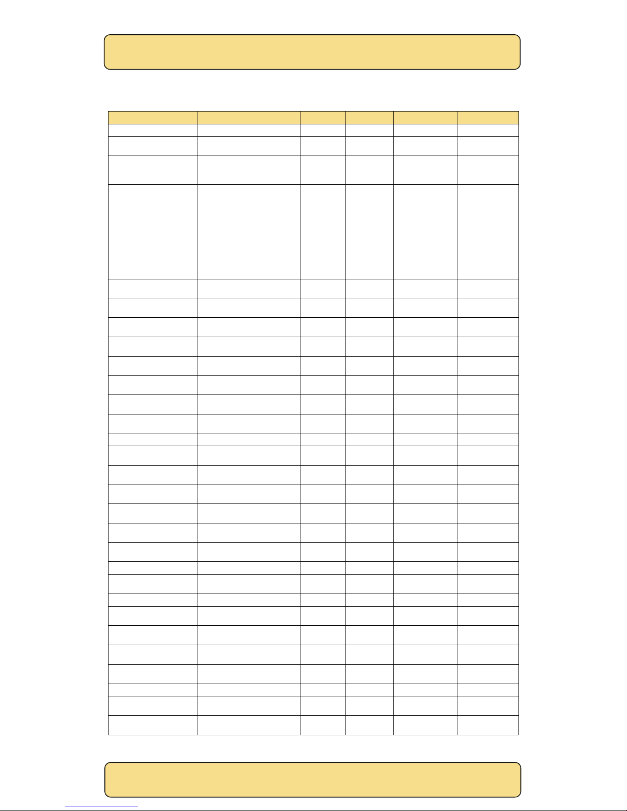
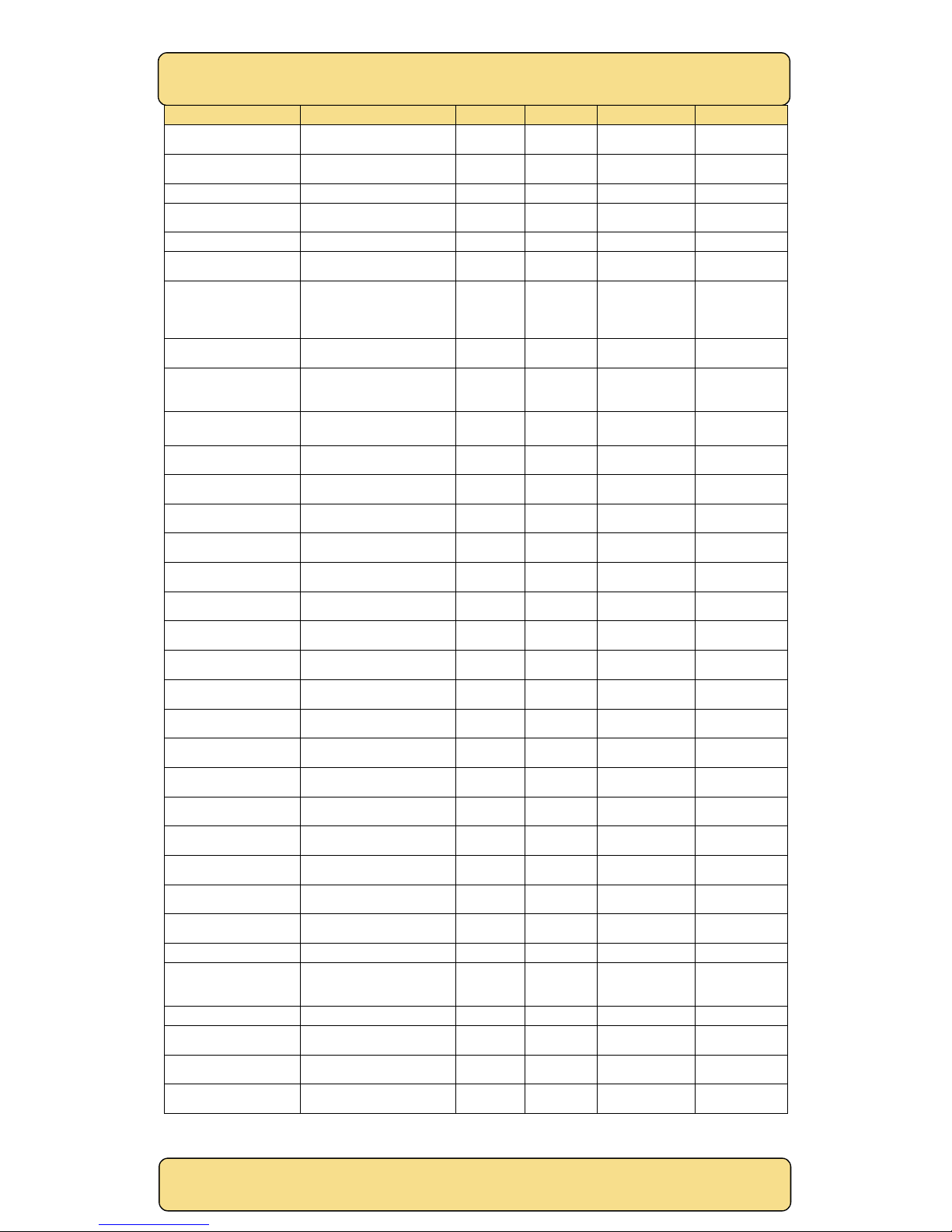
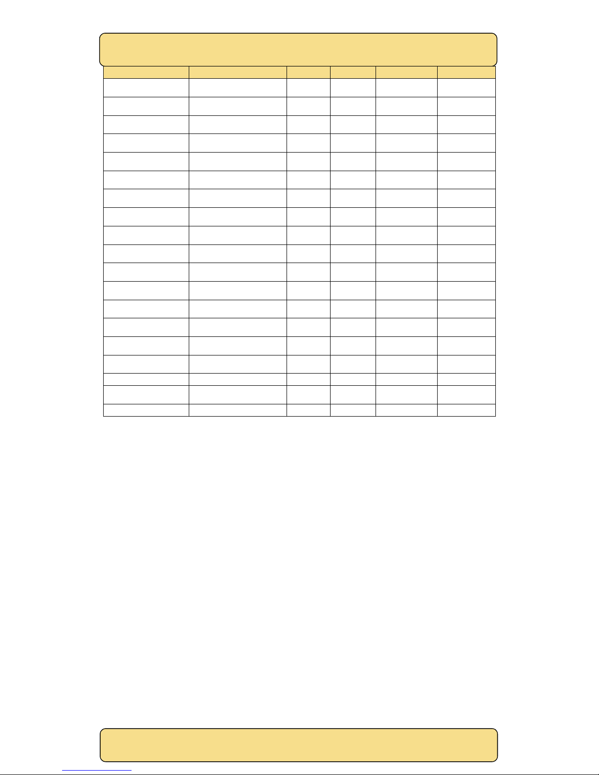
Appendix B: Bill of Materials
Component ID
Value
Quantity
Supplier
Stock No.
Manufacturer
C1
CAP TANT 47UF 16V
20%
2312
1
Digi-Key
478-3912-1-ND
AVX
Corporation
C2, C3, C6, C26, C35,
C42, C51, C53, C54, C57,
C59, C72, C81
CAP TANT 10UF 10V 20%
0805
13
Digi-Key
478-8192-1-ND
AVX
Corporation
C4, C5, C9, C10, C11, C12,
C13, C14, C22, C23, C24,
C25, C27, C28, C29, C30,
C31, C32, C33, C34, C36,
C37, C43, C45, C46, C47,
C48, C49, C50, C52, C55,
C56, C58, C60, C63, C65,
C66, C68, C69, C70, C71,
C73, C74, C76, C77, C78,
C79, C80, C84, C85, C86
CAP CER 0.1UF 25V 10% X5R
0603
51
Digi-Key
478-1244-2-ND
AVX
Corporation
C7,
C20, C39, C41
CAP CERM .01UF 10% 50V
X7R 0603
4
Digi-Key
478-1227-1-ND
AVX
Corporation
C8, C21
CAP CER 2.2UF 10V 10% X5R
0603
2
Digi-Key
478-6212-1-ND
AVX
Corporation
C15, C16, C17, C18, C19
CAP 100NF, 10V, 0402
5
Digi-Key
478-1129-1-ND
AVX
Corporation
C38, C40, C64, C67
CAP CER 10UF 10V 10% X5R
0805
4
Digi-Key
478-5167-1-ND
AVX
Corporation
C44
CAP CER 1000PF 50V 10%
X7R 0603
1
Digi-Key
478-1215-1-ND
AVX
Corporation
C61,C62
CAP CER 10PF 50V 5% NP0
0603
2
Digi-Key
478-1163-1-ND
AVX
Corporation
C75
CAP
TANT 22UF 10V 20%
0805
1
Digi-Key
478-3117-2-ND
AVX
Corporation
C82,C83
CAP CER 4.7UF 6.3V 10% X5R
0603
2
Digi-Key
478-5009-1-ND
AVX
Corporation
D1
DIODE SCHOTTKY 40V 3A
SMB
1
Digi-Key
B340LB
-
FDICT
-NDDiodes Inc.
D2
DIODE ZENER 7.5V 5W
DO214AA
1
Digi-Key
SMBJ5343B
-
TPMSCT-ND
Micro
Commercial
D3
LED RA 565NM GREEN WTR
CLR SMD
1
Digi-Key67-
1557-1-ND
Lumex
D4
LED RA 585NM YELLOW
WTR CLR SMD
1
Digi-Key67-
1558-1-ND
Lumex
D5,D6
DIODE SCHOTTKY 30V
200MA SOT323
2
Digi-Key
BAT54SW
-
FDICT-ND
Diodes Inc.
D7,D8
DIODE SCHOTTKY 30V
200MA SOT323
2
Digi-Key
BAT54AW
-
FDICT-ND
Diodes Inc.
F1
PTS RESETBLE 24V 0.750A
1210
1
Digi-Key
F4146CT
-NDLittelfuse Inc.
J1
CONN POWER JACK 2.1MM
PCB
1
Digi-KeyCP-
202A-ND
CUI Inc.
J2
CONN HEADER LOPRO STR
10POS GOLD
1
Digi-Key
A33159
-NDTE
Connectivity
J3,J4
CONN BNC JACK R/A 75
OHM PCB
2
Digi-KeyC-SX-
108
Cambridge
Connectors
J5
CONN MOD JACK 8P8C R/A
SHIELDED
0
Digi-Key
151-1061-ND
EDAC Inc.
L1
DIGITAL NOISE FILTER
200KHZ SMD
1
Digi-Key
P13159CT
-NDPanasonic
L2,L3
FERRITE CHIP 220 OHM
200MA 0603
2
Digi-Key
490-5985-1-ND
Murata
Page 33
SingMai Electronics
SM08
User Manual Revision 0.
2
Page33of
36
Component ID
Value
Quantity
Supplier
Stock No.
Manufacturer
L4
INDUCTOR 120NH 5% 0603
SMD
1
Digi-Key
PCD1986CT
-NDPanasonic
L5
INDUCTOR HI FREQ 6.8NH
5% 0603
1
Digi-Key
587-1543-1-ND
Taiyo Yuden
Q1,Q2,Q3,Q4
TRANS NPN 40V SOT
-234
Digi-Key
SMBT3904INCT
-NDInfineon
R1
RES 22 OHM .5W 5% 1206
SMD
1
Digi-Key
541-22UACT
-NDVishay Dale
R2, R3, R4, R5, R7, R8,
R12, R17, R18, R19, R20,
R21, R22, R23, R38, R39,
R40, R41
RES 10.0K
OHM 1/10W 1%
0603 SMD
18
Digi-Key
541-10.0KHCT
-NDVishay Dale
R6
RES 24.0 OHM 1/10W 1%
0603 SMD
1
Digi-Key
541-24.0HCT
-NDVishay Dale
R9, R24, R30, R31, R32,
R33, R46, R47, R51, R52,
R56, R57, R58
RES 1.00K OHM 1/10W 1%
0603 SMD
13
Digi-Key
541-1.00KHCT
-NDVishay Dale
R10,R25,R65,R66,R72,R7
3
RES 120 OHM 1/10W 1% 0603
SMD
6
Digi-Key
541-120HCT
-NDVishay Dale
R11,R42
RES 100K OHM 1/10W 1%
0603 SMD
2
Digi-Key
541-100KHCT
-NDVishay Dale
R13,R36,R48,R49
RES 33.0 OHM 1/10W 1%
0603 SMD
4
Digi-Key
541-33.0HCT
-NDVishay Dale
R14,R15,R16,R54,R70
RES 4.7K OHM 1/10W 1%
0603 SMD
5
Digi-Key
541-4.70KHCT
-NDVishay Dale
R26,R53,R59,R60,R61,R6
4
RES 75.0 OHM 1/10W 1%
0603 SMD
6
Digi-Key
541-75.0HCT
-NDVishay Dale
R27
RES 470 OHM 1/10W 1% 0603
SMD
1
Digi-Key
541-470HCT
-NDVishay Dale
R28,R29
RES 47.0K OHM 1/10W 1%
0603 SMD
2
Digi-Key
541-47.0KHCT
-NDVishay Dale
R34
RES 300 OHM 1/10W 1% 0603
SMD
1
Digi-Key
541-300HCT
-NDVishay Dale
R35
RES 100 OHM 1/10W 1% 0603
SMD
1
Digi-Key
541-100HCT
-NDVishay
Dale
R37
RES 330 OHM 1/10W 1% 0603
SMD
1
Digi-Key
541-330HCT
-NDVishay Dale
R43
RES 2.20K OHM 1/10W 1%
0603 SMD
1
Digi-Key
541-2.20KHCT
-NDVishay Dale
R44,R45,R71
RES 4.99 OHM 1/10W 1%
0603 SMD
3
Digi-Key
541-4.99KHCT
-NDVishay Dale
R50
RES 2.0K OHM
1/10W 1%
0603 SMD
1
Digi-Key
541-2.00KHCT
-NDVishay Dale
R62
RES 8.06K OHM 1/10W 1%
0603 SMD
1
Digi-Key
541-8.06KHCT
-NDVishay Dale
R63
RES 499 OHM 1/10W 1% 0603
SMD
1
Digi-Key
541-499HCT
-NDVishay Dale
R67,R74
RES 169 OHM 1/10W 1% 0603
SMD
2
Digi-Key
541-169HCT
-NDVishay Dale
R68
RES 25.5 OHM 1/10W 1% 0603
SMD
1
Digi-Key
541-25.5HCT
-NDVishay Dale
R69
RES 1.0 OHM 1/10W 5% 0603
SMD
1
Digi-Key
541-1.0GCT
-NDVishay Dale
SW1
SWITCH TAPE SEAL 5 POS
SMD 50V
1
Digi-Key
CT2195MST
-NDCTS
Electrocompo
nents
U1
IC REG LDO 1A PREC 3.3V
SOT-223
1
ExcelPoint
ADP3338AKCZ
-
3.3RL7CT-ND
Analog
Devices
U2
IC REG LDO 2.5V 1A SOT223
-31
ExcelPoint
ADP3338AKCZ
-
2.5RL7CT-ND
Analog
Devices
U3
IC REG LDO 1.2V 0.5A
8MSOP
1
ExcelPoint
ADP1715ARMZ
-
1.2-R7
Analog
Devices
Page 34
SingMai Electronics
SM08
User Manual Revision 0.
2
Page34of
36
Component ID
Value
Quantity
Supplier
Stock No.
Manufacturer
U4
IC REG LDO 2.5V 0.5A
8MSOP
1
ExcelPoint
ADP1715ARMZ
-
2.5-R7
Analog
Devices
U5
IC FPGA 89 I/O 164MBGA
EP4CE15M8I7N
1
Cytech
544-2789-ND
AlteraU6IC FLASH 4MBIT 86MHZ
8SOP
1
SingMai
1092-1114-ND
Macronix
U7
IC OPAMP
GP 400KHZ RRO
TSOT23-5
1
DigiKey
AD8603AUJZRE
EL7CT-ND
Analog
Devices
U8
ADVANCED ALGORITHM
PERMISSION UNIT
1
Neowine
ALPU-MP
Neowine
U9,U12
IC OPAMP GP 240MHZ RRO
8SOIC
2
ExcelPoint
ADA4891
-
2ARZ
-R7Analog
Devices
U10
IC OPAMP GP 240MHZ RRO
SOT23-5
1
ExcelPoint
ADA4891
-
1ARJZ
-
R7CT-ND
Analog
Devices
U11
IC AMP VGA LOW NOISE 8
-
LFCSP
1
ExcelPoint
AD8337BCPZ
-
REEL7
Analog
Devices
U13
IC OPAMP VFB 80MHZ RRO
8SOIC
1
Digi-Key
AD8032ARZ
-
REEL7CT-ND
Analog
Devices
U14
IC REG LDO 1A PREC 3.0V
SOT-223
1
ExcelPoint
ADP3338AKCZ
-3-
RL7CT-ND
Analog
Devices
U15
IC SCHMITT TRIG INV SOT
-
23-5
1
Digi-Key
296-11607-1-ND
Texas
Instruments
U16
IC OPAMP VFB 320MHZ
RRO SOT23-6
1
ExcelPoint
AD8063ARTZ
-
REEL7CT-ND
Analog
Devices
U17
IC SERIALIZER/CABLE DVR
48-LLP
1
Digi-Key
LMH0040SQE/N
OPBCT-ND
Texas
Instruments
U18
IC SWITCH SPST SOT23
-61
Digi-Key
ADG701LBRTZ
-
REEL7CT-ND
Analog
Devices
U19
IC ADC 10BIT 105MSPS 3V
32-LFCSP
1
ExcelPoint
AD9215BCPZ
-
105-ND
Analog
Devices
U20
IC CLK SYNTHESIZER HDTV
8SOIC
1
Digi-Key
800-2212-ND
IDTX1OSC VCXO 27.000MHZ 3.3V
SMD
1
Digi-Key
535-9345-1-ND
Abracon
Table 4 SM08 Bill of Materials.
Page 35
SingMai Electronics
SM08
User Manual Revision 0.
2
Page35of
36
Appendix C: AC-DC adaptor
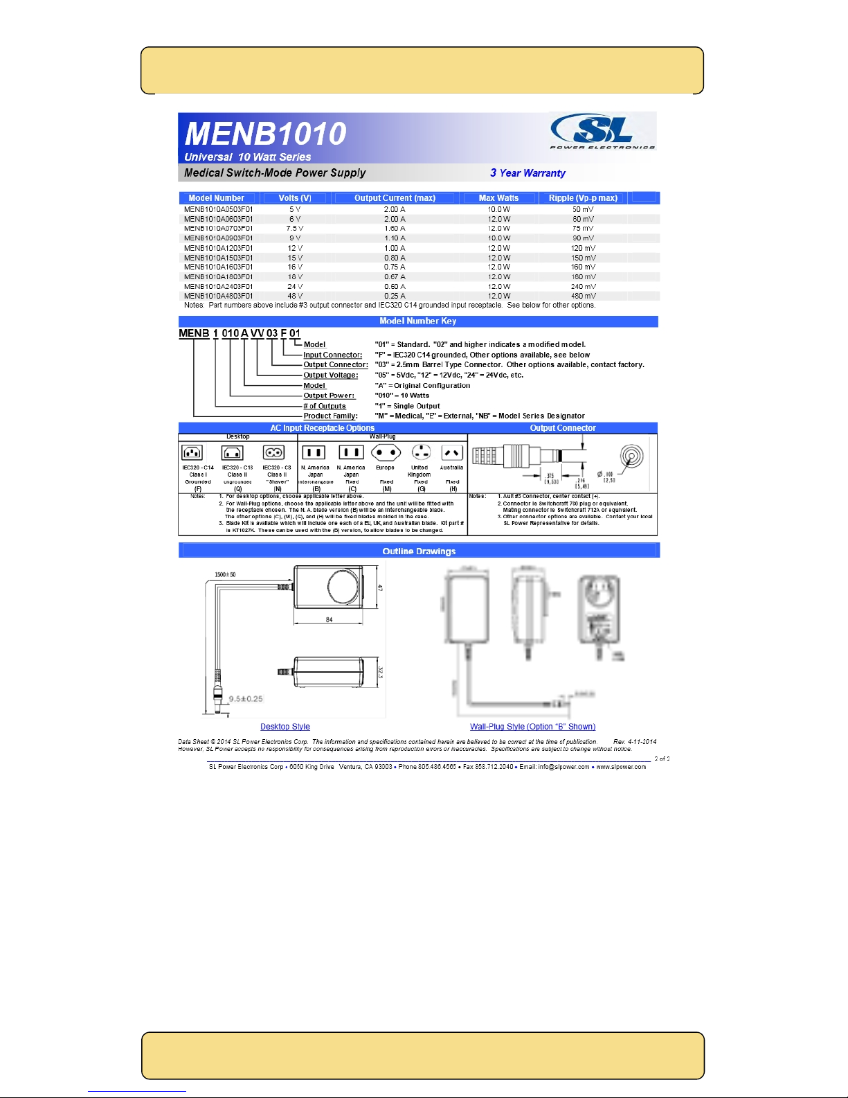
The specification for the supplied AC-DC adaptor is shown in Figures 30 and 31.
Figure 30 AC-DC adaptor specification- Page 1.
Page 36
SingMai Electronics
SM08
User Manual Revision 0.
2
Page36of
36
Figure 31 AC-DC adaptor specification- Page 2.
 Loading...