

Page 1

1
SM02
High Definition Video Encoder
and
Pattern Generator
User Manual
Revision 0.1
15th March 2015
Page 2

2
Contents
Contents ........................................................................................................ 2
Tables ........................................................................................................... 2
Figures .......................................................................................................... 3
1. Introduction ........................................................................................... 4
2. aCVi Overview ...................................................................................... 6
3. Connecting up the SM02 ...................................................................... 8
4. Quick Start Guide ............................................................................... 11
Switch On and Control ............................................................................ 11
Menu control ........................................................................................... 13
5. SM02 Patterns .................................................................................... 21
75% Colour bars ..................................................................................... 21
100% Colour bars ................................................................................... 21
SMPTE Colour bars ................................................................................ 22
Ramp ...................................................................................................... 24
5-step staircase ...................................................................................... 25
2T30T ..................................................................................................... 25
Multiburst ................................................................................................ 26
15MHzSw ............................................................................................... 27
30MHzSw ............................................................................................... 27
Black ....................................................................................................... 28
White ....................................................................................................... 28
50%Grey ................................................................................................. 29
Red ......................................................................................................... 29
Green ...................................................................................................... 29
Blue ......................................................................................................... 29
Xhatch ..................................................................................................... 29
SDI PLL .................................................................................................. 29
Matrix ...................................................................................................... 29
Zone Plate .............................................................................................. 30
5. SM02 Noise generator ............................................................................ 32
6. aCVi Data transfer protocol ................................................................ 33
Appendix A: Power supply specification ..................................................... 36
Tables
Table 1 aCVi output specification. ................................................................ 9
Table 2 Analogue Component output Specifications .................................. 10
Table 3 HD-SDI Output Specifications ....................................................... 10
Table 4 HD-SDI Input specification. ............................................................ 10
Table 5 SM02 Patterns. .............................................................................. 16
Table 6 aCVi Control words Transmitter > Receiver .................................. 34
Page 3

3
Figures
Figure 1 aCVi Spectrum. ...............................................................................7
Figure 2 SM02 rear panel. .............................................................................8
Figure 3 SM02 AC-DC converter ...................................................................9
Figure 4 SM02 Front panel. ........................................................................ 11
Figure 5 SM02 Menu structure. .................................................................. 13
Figure 6 aCVi output, 30MHz sweep (Pre-emphasis = minimum). ............ 19
Figure 7 aCVi output, 30MHz sweep (Pre-emphasis = maximum). ........... 20
Figure 8 75% Component colour bar waveform. ........................................ 21
Figure 9 100% Colour bar waveform. ......................................................... 22
Figure 10 SMPTE Colour Bar component waveform. ................................ 23
Figure 11 SMPTE Reverse colour bars waveform. .................................... 23
Figure 12 SMPTE Pluge waveform. ........................................................... 24
Figure 13 Limit ramp waveform. ................................................................. 24
Figure 14 10-step waveform. ...................................................................... 25
Figure 15 2T30T pulse waveform. .............................................................. 26
Figure 16 Multiburst waveform. .................................................................. 26
Figure 17 15MHz frequency sweep waveform. .......................................... 27
Figure 18 30MHz sweep waveform. ........................................................... 28
Figure 19 30MHz sweep markers. .............................................................. 28
Figure 20 Matrix test signal......................................................................... 30
Figure 21 . Left side: The zone plate shows flickering colours at the
subcarrier frequency because of crosstalk between the luma and the
chroma. Right side: No crosstalk issues..................................................... 31
Figure 22 Hum generator............................................................................ 32
Figure 23 aCVi Data format. ....................................................................... 33
Page 4

4
1. Introduction
SM02 is a video encoder and pattern generator supporting high definition
video standards.
As a video pattern generator, SM02 can generate 19 line based patterns
which are output as simultaneous HD-SDI (SMPTE-272M), YPbPr
component and aCVi.
Standards supported are:
720p/25Hz-30Hz-50Hz-59.94Hz-60Hz
1080p/24Hz-25Hz-29.97Hz-30Hz
1080i/50Hz-59.94Hz-60Hz
Patterns available include:
75%/100%/SMPTE colour bars
Black/White/50% Grey/Red/Green/Blue flat fields
2T, 30T and Pulse bar
Multiburst
15/7.5MHz and 30/15MHz luma/chroma frequency sweeps
5 step linearity
Crosshatch
5 pattern matrix pattern
Pathological (HD-SDI test)
Circular Zone Plate
In addition programmable amplitude white noise and/or 50Hz or 60Hz hum
may be added to the YPbPr (Y channel) and aCVi outputs.
As a video encoder SM02 accepts SMPTE-272M inputs at any of the above
standards which it encodes to simultaneous HD-SDI (SMPTE-272M),
YPbPr component and aCVi outputs. Again noise and/or hum may be
added to the YPbPr and aCVi outputs.
Controls provided include:
aCVi amplitude
aCVi Luma amplitude
aCVi Chroma amplitude
aCVi Burst amplitude
Page 5

5
aCVi Sync amplitude
aCVi Black level
YPbPr Luma amplitude
YPbPr Pb/Pr amplitude
YPbPr Sync amplitude
YPbPr Black level
SM02 is powered by a universal input power supply and controlled with a
simple and intuitive selection menu.
Page 6

6
2. aCVi Overview
The following is a brief overview of the aCVi interface.
The basic concept of the aCVi interface is to build on the proven and
reliable transport method of NTSC, (the advantages of PAL – v.v. multi-path
reception – is not relevant to a cable system so NTSC is used as the
model). NTSC transmissions are capable of transmitting more than 1km
across RG-59 cable but the bandwidth is limited to 5MHz. NTSC also has
chroma/luma crosstalk issues that are difficult to resolve at the receiver
end.
Because the cable system is a closed system, it is only necessary for the
transmitter and receiver to ‘understand’ each other so we can modify the
basic NTSC method to suit HD transmissions.
The first thing to overcome is the bandwidth restrictions of the cable. HD
video transmission requires a luma bandwidth of 30MHz according to the
SMPTE-296M specification. Because we have only a single coaxial cable
for the transport we have chosen to transmit luma and colour difference
signals (as opposed to component red, green blue) as the colour difference
signals, because of the visual perception of the eye being less acute to
colour, can be sent at half or less of the luma bandwidth: for aCVi the
chroma bandwidth is 7.5MHz (effectively aCVi is 4:1:1 transmission).
To further reduce the bandwidth of the transmission the colour difference
signals are modulated onto a carrier in quadrature so they effectively use
the same bandwidth. However, to minimise the signal recovery problems of
NTSC, (and as we have no backward compatibility issues), the lower
sideband of the chroma and the luma high frequencies overlap minimally;
the chroma subcarrier for aCVi is set to ~41.4MHz. (See Figure 1).
For 300m of RG-59 cable we can expect 18dB loss at this frequency
(6.2dB/100m @ 50MHz). However the synchronizing signals are at a much
lower frequency where the loss is only about 1-2dB so reliable rastering of
the received signal should always be assured.
To simplify the high frequency compensation of the transmission, preemphasis is used. The degree of pre-emphasis is programmable to allow
for different cable lengths. The maximum pre-emphasis is set at 30dB and
the frequency response of the pre-emphasis is set to approximate the cable
characteristics.
Page 7

7
A further improvement in the SNR is achieved through transmitting a peak
to peak video level of 1.5V which maintains compatibility with any legacy
SD equipment on the network and also allows common low-power 5V
drivers to be used.
Figure 1 aCVi Spectrum.
ACVi also allows for the bidirectional transfer of data between receiver and
transmitter. One byte of data is transmitted in each direction per frame (i.e.
50bytes/second data rate for a 50Hz frame rate). The data rate is
deliberately kept low to reduce the effects of cable attenuation. Data is sent
using two dedicated lines in the vertical blanking interval.
Page 8
8
3. Connecting up the SM02
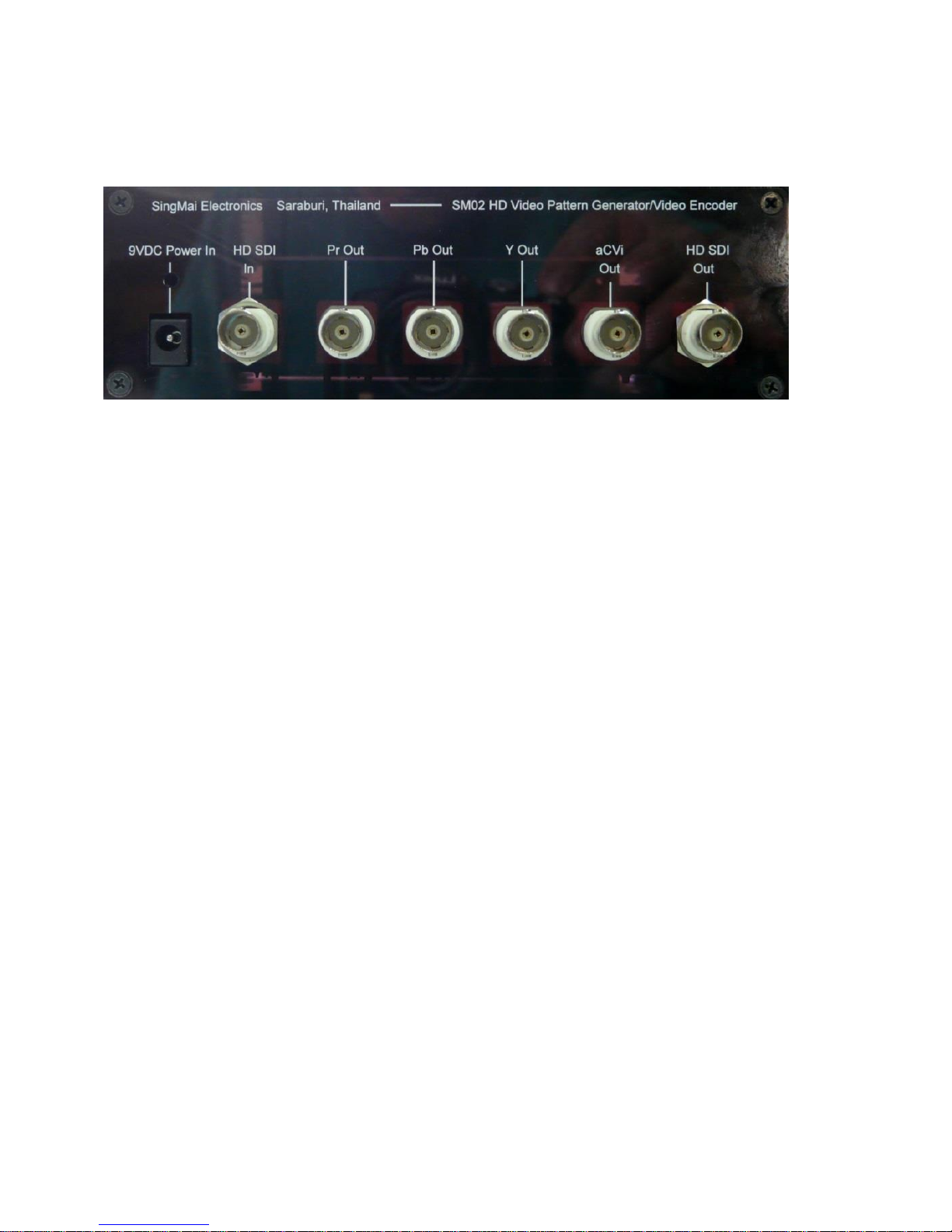
All connections to the SM02 are made via the rear panel: see Figure 2.
Figure 2 SM02 rear panel.
The AC-DC converter connects to the left hand jack. The SM02 input is
protected against reverse polarity and is fused against internal short circuits
or overloads. The converter supplied with the SM02 is a model MW173KB
manufactured by SL Power Electronics Corp. and provides 9VDC at 3A and
accepts AC inputs from 100-240VAC. Connect the supplied power cord to
the AC-DC converter and output DC of the converter to the 9VDC Power In
input of the SM02.
Page 9

9
Figure 3 SM02 AC-DC converter
A full specification for the supplied AC-DC converter may be found in
Appendix A.
The SM02 provides both analogue and digital component outputs for
connecting to the equipment under test.
The aCVi output is connected to the BNC, ‘aCVi Out’. The specification for
the output is shown in Table 1.
Parameter
Specification
Comments
Connector Type
BNC
Output impedance
75Ω
Output return loss
>30dB
0 - 37.125MHz
aCVi output level
1.5V pk.pk
Nominal peak Y to sync tip
for 100% colour bars input
Table 1 aCVi output specification.
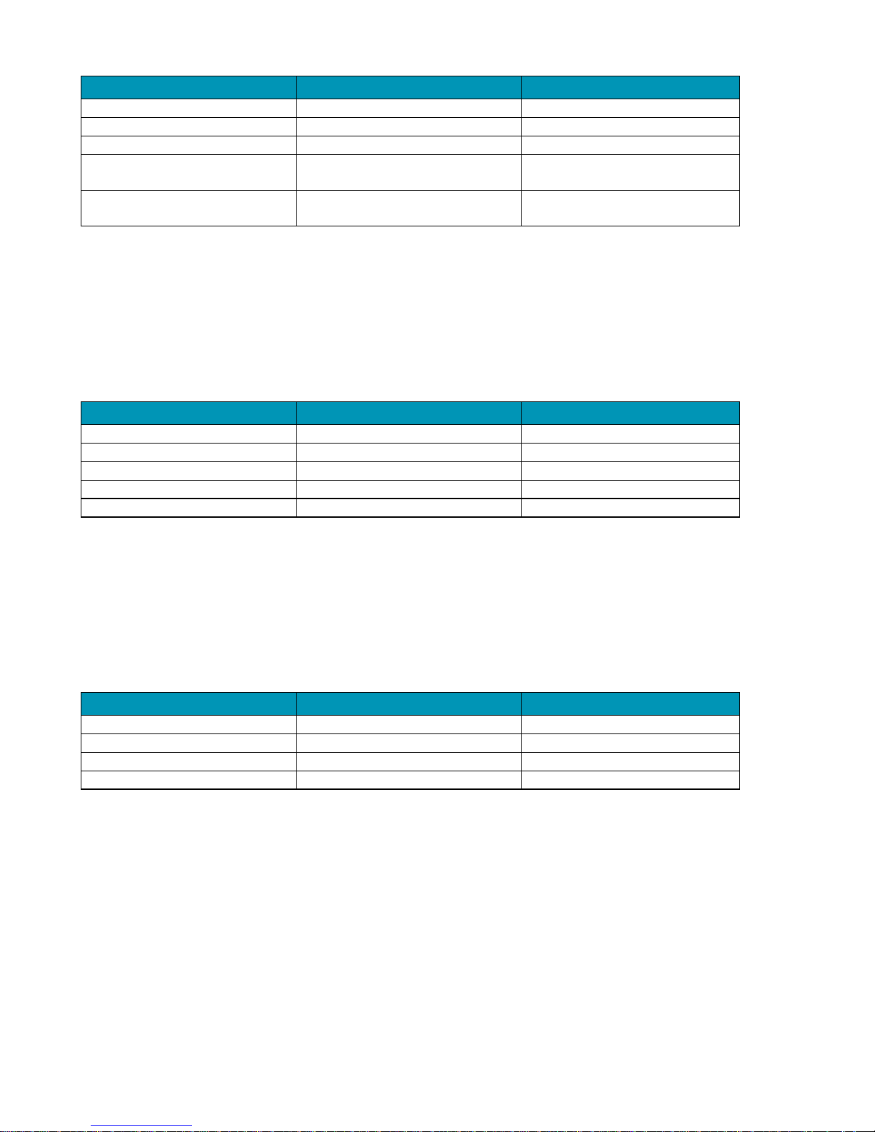
The analogue component outputs are connected to the BNCs, ‘Y Out’, ‘Pb
Out’ and ‘Pr Out’. The specification for the outputs is shown in Table 2.
Page 10
10
Parameter
Specification
Comments
Connector Type
BNC
Output impedance
75Ω
Output return loss
>30dB
0-5MHz
Y output level
1.0V pk.pk
Nominal 100% colour bars
input
Cb/Cr output levels
±350mV pk-pk
Nominal 100% colour bars
input
Table 2 Analogue Component output Specifications
The serial digital interface (HD-SDI) output is connected to the ‘HD SDI Out’
BNC and its specifications are shown in Table 3.
The HD-SDI output conforms to the SMPTE-272M specification.
Parameter
Specification
Comments
Connector Type
BNC
Output impedance
75Ω
Fixed termination
Output return loss
>15dB
50Hz-1.485GHz
Output level
800mV pk-pk ± 10%
Jitter
<0.2UI
Table 3 HD-SDI Output Specifications
The serial digital interface (HD-SDI) input (only used in encoder mode) is
connected to the ‘HD SDI In’ BNC and its specifications are shown in Table
4.
The HD-SDI input conforms to the SMPTE-272M specification.
Parameter
Specification
Comments
Connector Type
BNC
Input impedance
75Ω
Fixed termination
Input return loss
>15dB
50Hz-1.485GHz
Input level
800mV pk-pk
Nominal
Table 4 HD-SDI Input specification.
Page 11
11
4. Quick Start Guide
Switch On and Control
Connect the AC-DC converter 9VDC cable into the rear panel power in
socket. Connect the AC supply to a local AC supply between 110-240VAC.
The Standby LED should light. Push the Adjust control and the unit will
switch on and the welcome message will be displayed (SingMai SM02).
To switch off the SM02 push the Adjust control again.
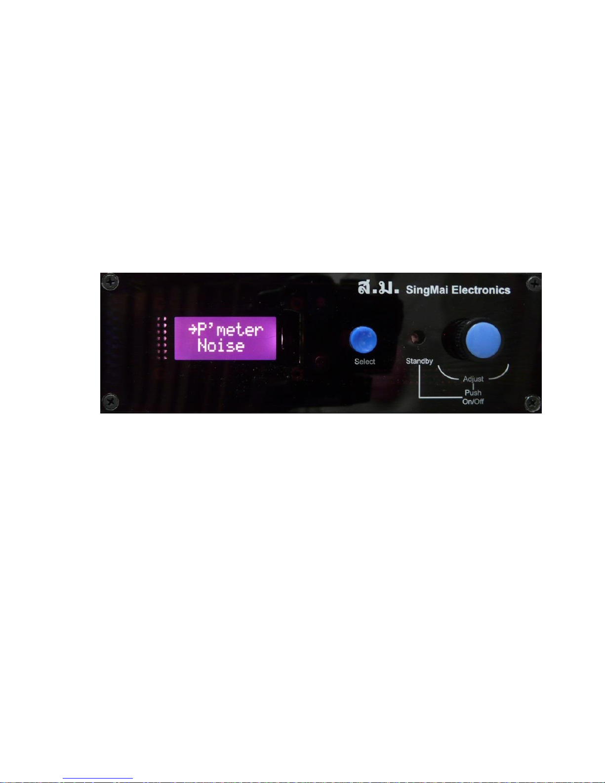
The front panel of the SM02 is shown in Figure 4.
Figure 4 SM02 Front panel.
There are just two controls for the SM01. The right hand control (Adjust)
switches the unit between On and Standby by pushing it whilst also
adjusting the value of parameters by rotating the knob left or right. The
central switch (Select) selects the chosen menu parameter and switches
preset parameters between, for example, on and off.
After the welcome message is displayed the LCD display will show the
available top level menus. A left hand arrow indicates which menu is
‘active’. Rotating the Adjust control will show all the available menus; after
the last of the menus an up arrow is shown.
To select a menu ensure the left arrow is by the side of the required top
level menu and press the Select button. Those menu options will then be
displayed.
Page 12

12
To change a parameter within the lower menu choices choose the required
item by aligning the left arrow with it and press the Select button. The
parameter will either toggle between the available options (e.g. On or Off)
or will show a menu bar where to can select more options via the Adjust
control. Once you have chosen the setting you require press the Select
button to return to the menu choices.
The Adjust control is also used to set the parameter values. Once set the
required value, press the Select button to retain that value and return to the
menu.
To return to the top level menu scroll down the menu choices using the
Adjust control; the last one before the up arrow will show Exit. Select this
by pressing the Select button and you will return to the top level menus.
Page 13
13
Menu control
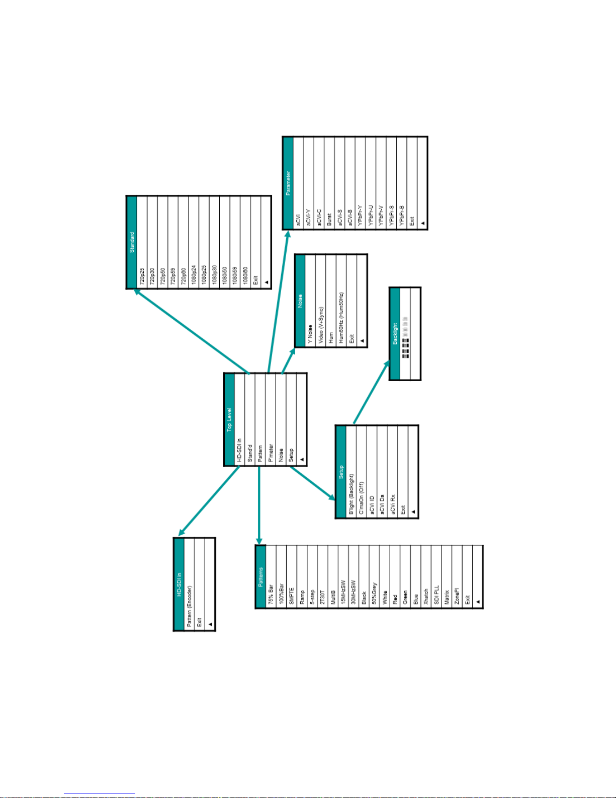
The complete menu structure is shown in Figure 4.
Figure 5 SM02 Menu structure.
Page 14

14
The following is a brief description of the menu functions.
HDSDI in:
Pattern (Encoder)
Each button press toggles between the internal patterns (Pattern – default
value) and the serial digital (HD-SDI) input (Encoder).
Exit
Returns to the top level menus.
Stand’d (Standard):
In Encoder mode the HD-SDI input standard must match the output
standard selection. (i.e. if the HD-SDI input is 1080p/30Hz, selecting
standards other than this can result in corrupted outputs).
720p/25
Forces 720p/25Hz output standard for the HD-SDI, YPbPr and aCVi
outputs. (Note, a number of items of video equipment do accept this output
standard.)
720p/30
Forces 720p/30Hz output standard for the HD-SDI, YPbPr and aCVi
outputs. (Note, a number of items of video equipment do accept this output
standard.)
720p/50
Forces 720p/50Hz output standard for the HD-SDI, YPbPr and aCVi
outputs.
720p/59
Forces 720p/59.94Hz output standard for the HD-SDI, YPbPr and aCVi
outputs. (Pixel clock frequency is 74. 74.17582418MHz.)
720p/60
Forces 720p/60Hz output standard for the HD-SDI, YPbPr and aCVi
outputs. (Default output standard).
1080p/24
Forces 1080p/24Hz output standard for the HD-SDI, YPbPr and aCVi
outputs.
Page 15

15
1080p/25
Forces 1080p/25Hz output standard for the HD-SDI, YPbPr and aCVi
outputs.
1080p/29
Forces 1080p/29.97Hz output standard for the HD-SDI, YPbPr and aCVi
outputs. (Pixel clock frequency is 74. 74.17582418MHz.)
1080p/30
Forces 1080p/24Hz output standard for the HD-SDI, YPbPr and aCVi
outputs.
1080i/50
Forces 1080i/50Hz output standard for the HD-SDI, YPbPr and aCVi
outputs. (2:1 interlaced output – frame rate = 25Hz.)
1080i/59
Forces 1080i/59.94Hz output standard for the HD-SDI, YPbPr and aCVi
outputs. (Pixel clock frequency is 74. 74.17582418MHz. 2:1 interlaced
output – frame rate = 29.97Hz.)
1080i/60
Forces 1080i/60Hz output standard for the HD-SDI, YPbPr and aCVi
outputs. (2:1 interlaced output – frame rate = 30Hz.)
Exit
Returns to the top level menus.
The specifications for the standards are shown in Appendix A.
Pattern:
Selects the output pattern when in ‘Pattern’ mode. (In ‘Encoder’ mode the
pattern menu operates but the pattern will not appear on the output.
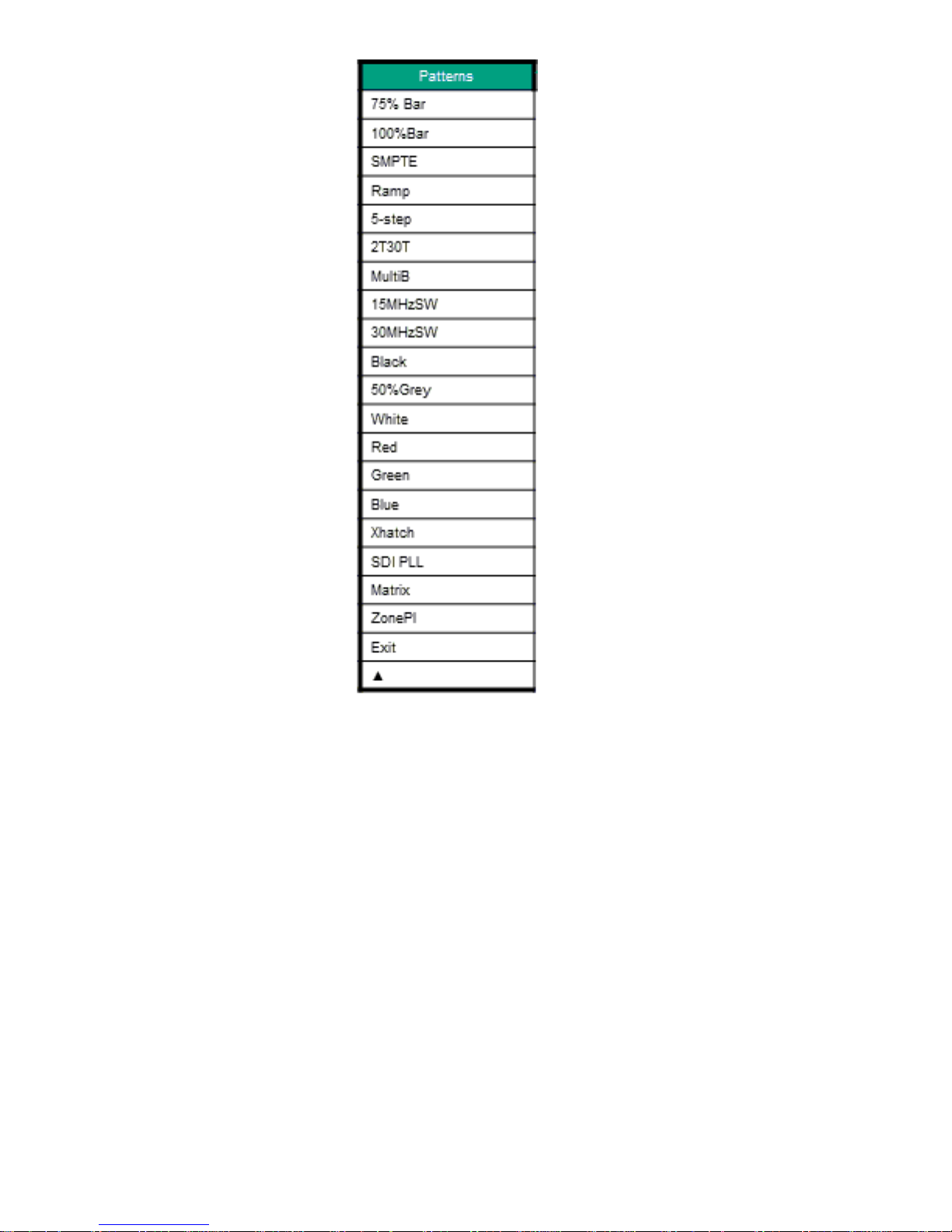
Table 5 lists the patterns available for each standard. A full description of
the patterns can be found in Chapter 4.
Page 16
16
Table 5 SM02 Patterns.
P’meter (Parameter):
Note that some combinations of the parameter setting can give invalid
outputs and may result in clipping of the signal.
aCVi
Adjusts the output amplitude of the composite aCVi video output. Default
value is 100% (gain of 1). Range is 0-130%.
aCVi-Y
Adjusts the output amplitude of the luma component of the aCVi video
output. Default value is 100% (gain of 1). Range is 0-130%.
Page 17

17
aCVi-C
Adjusts the output amplitude of the chroma component of the aCVi video
output. Default value is 100% (gain of 1). Range 0-130%.
Burst
Adjusts the output amplitude of the colour burst of the aCVi video output.
Default value is 100% (gain of 1). Range 0-130%.
aCVi-S
Adjusts the output amplitude of the synchronizing signals of the aCVi video
output. Default value is 100% (gain of 1). Range is 0-130%.
aCVi-B
Adjusts the output black level of the composite video output. Default value
is 0 (offset of 0mV). Range is ±100.
YPbPr-Y
Adjusts the output amplitude of the luma (Y channel) of the component
YPbPr analogue video output. Default value is 100% (gain of 1). Range is
0-130%.
YPbPr-U
Adjusts the output amplitude of the Pb of the component YPbPr analogue
video output. Default value is 100% (gain of 1). Range is 0-130%.
YPbPr-V
Adjusts the output amplitude of the Pr of the component YPbPr analogue
video output. Default value is 100% (gain of 1). Range is 0-130%.
YPbPr-S
Adjusts the output amplitude of the synchronizing signals of the component
Y analogue video output. Default value is 100% (gain of 1). Range is 0130%.
YPbPr-B
Adjusts the black level value of the luma component of the component
YPbPr analogue video output. Default value is 100 (offset of 0mV). Range
is ±100.
Exit
Returns to the top level menus.
Page 18

18
Noise:
Y Noise
Selects a sub menu which allows control of the amplitude of white noise
injected into the Y output channel of the YPbPr analogue output and the Y
component of the aCVi composite video output. The range of the control is
from 0 (off – default value) to 100 (maximum noise). A fuller description of
the noise generator may be found in Chapter 5.
Video (V+Sync)
The injected noise (white noise) is limited to the active video portion of the
analogue output waveform (Video – default value) or the entire waveform
(V+Sync).
Hum
Selects a sub menu which allows control of the amplitude of hum injected
into the Y output channel of the YPbPr analogue output and the aCVi video
output.. The range of the control is from 0 (off – default value) to 100
(maximum hum). A fuller description of the noise generator may be found in
Chapter 5.
Hum60Hz (Hum50Hz)
Selects frequency of the hum (50Hz or 60Hz).
Exit
Returns to the top level menus.
Setup:
B’light
Controls the brightness of the front panel LCD backlight. Default value is ‘4’.
C’maOn (C’maOff)
Turns off the chroma component of the HD-SDi, YPbPr and aCVi outputs.
Default value is chroma on (C’maOn).
aCVi ID
Allows the ID component of the transmitter data to be set. (See chapter 6).
Values can be between 0 and 15.
aCVi Da
Allows the data component of the transmitter data to be set. (See chapter
6). Values can be between 0 and 255.
Page 19
19
aCVi Rx
Displays the received ID and data words from the aCVi receiver (if present).
aCVi PE
Manual control of the pre-emphasis filter for the aCVi interface. The value is
between 0 (minimum) and 255 (maximum).
The degree of pre-emphasis set is dependent on the cable length and is
designed to approximately compensate for the high frequency loss of
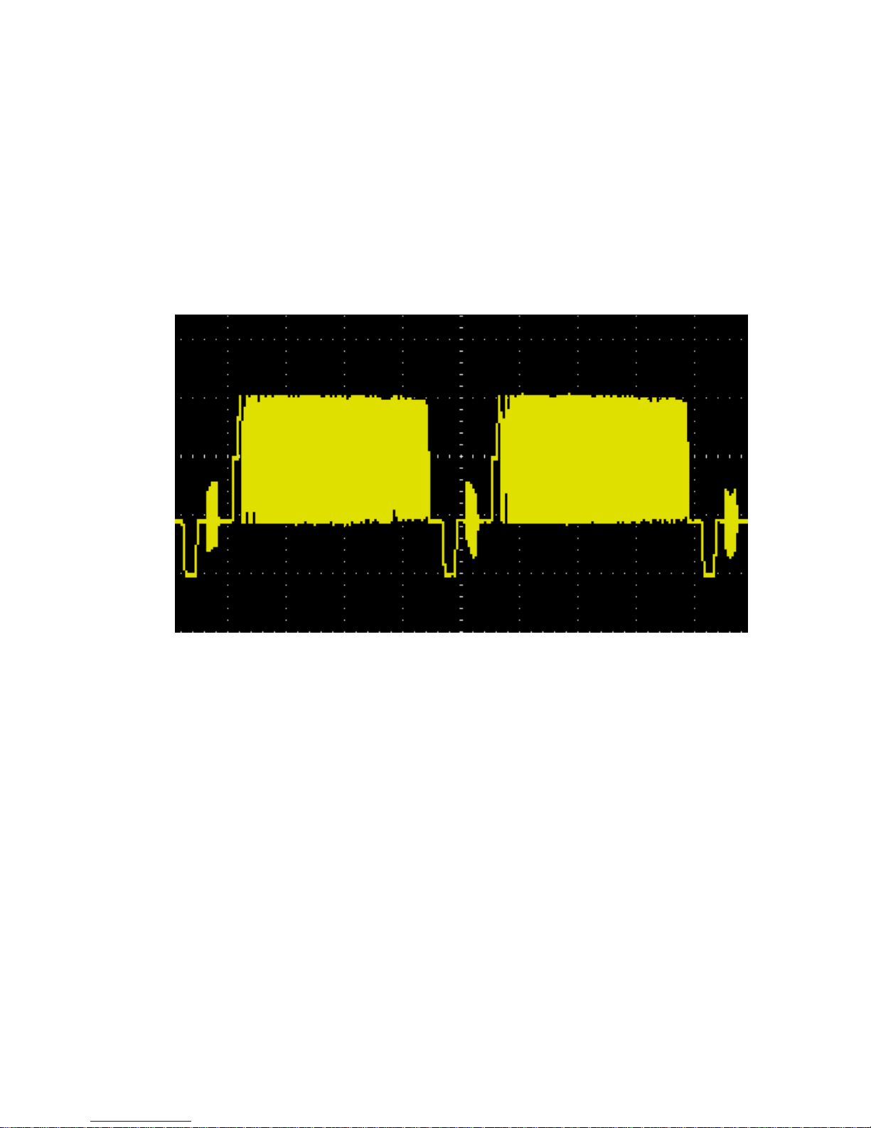
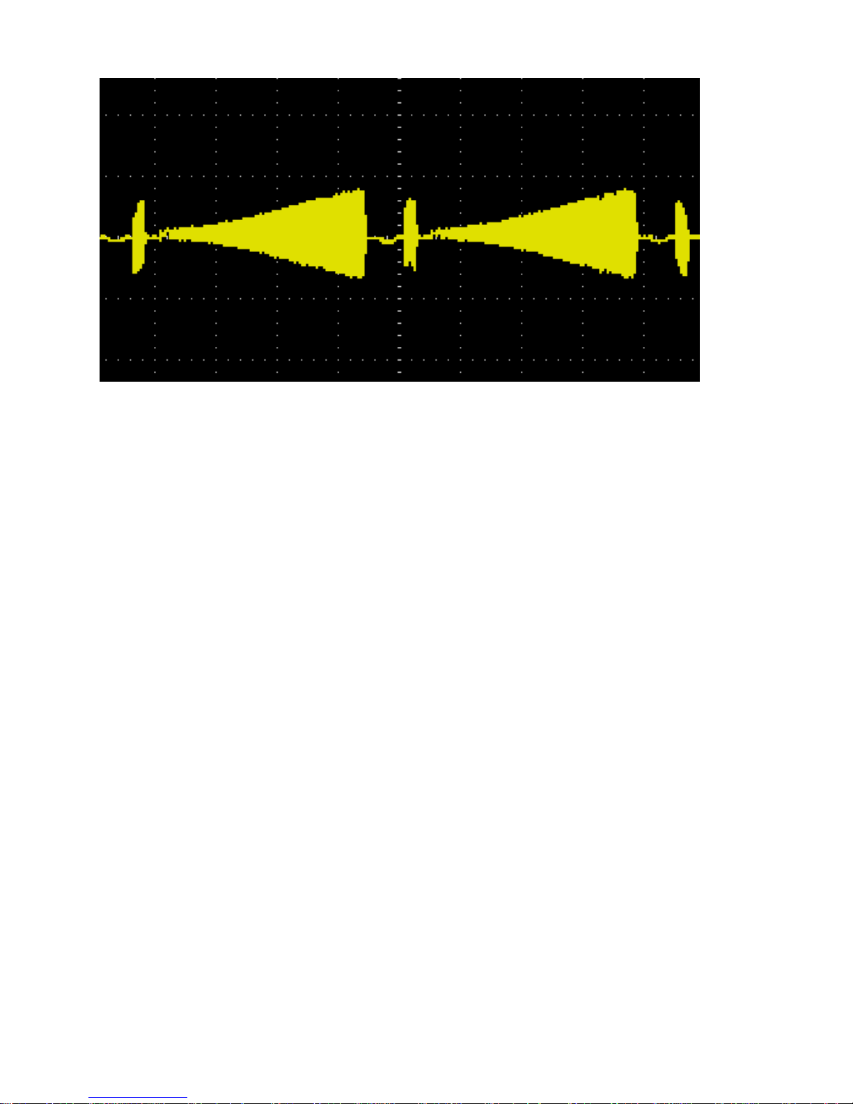
>300m of RG-59 or UTP cable. Figures 6 and 7 show the aCVi output with
a 30MHz frequency sweep with minimum and maximum pre-emphasis set.
Figure 6 aCVi output, 30MHz sweep (Pre-emphasis = minimum).
Page 20
20
Figure 7 aCVi output, 30MHz sweep (Pre-emphasis = maximum).
Exit
Returns to the top level menus.
Page 21
21
5. SM02 Patterns
Below is a detailed description of each of the SM02 patterns.
75% Colour bars
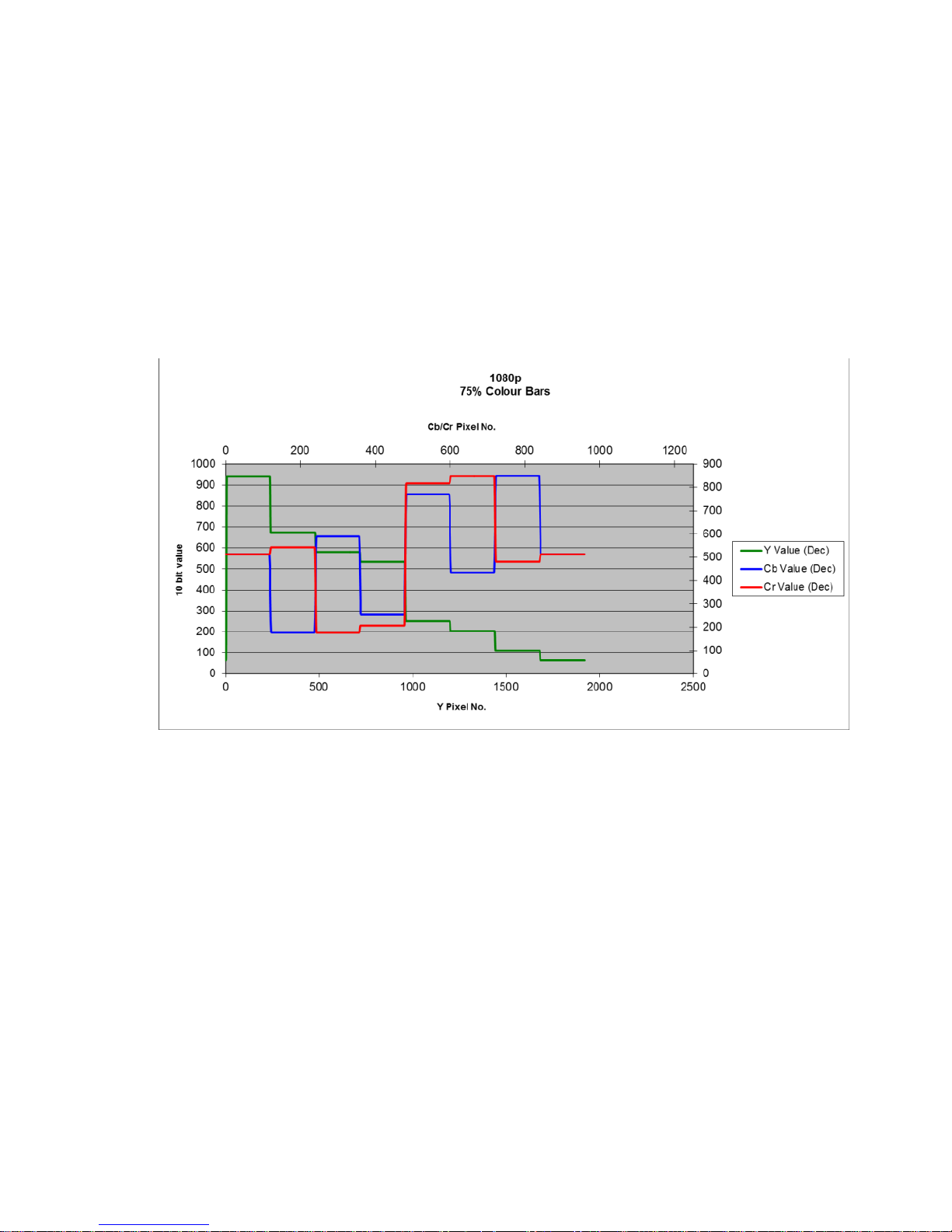
75% colour bars are used for measuring insertion gain, chroma level and
chroma gain and for monitor alignment. The SM02 generates full frame
75% saturated colour bars with a 100% white bar reference. The colour bar
sequence is white, yellow, cyan, green, magenta, red, blue and black.
Figure 8 75% Component colour bar waveform.
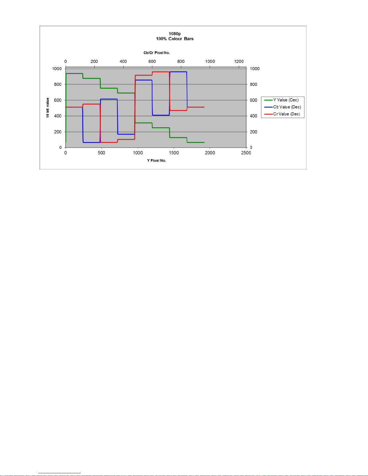
100% Colour bars
100% colour bars are used for measuring insertion gain, chroma level and
chroma gain and for monitor alignment. The SM02 generates full frame
100% saturated colour bars with a 100% white bar reference. The colour
bar sequence is white, yellow, cyan, green, magenta, red, blue and black.
Page 22
22
Figure 9 100% Colour bar waveform.
SMPTE Colour bars
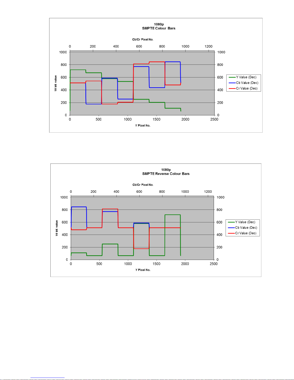
67% of the SMPTE colour bar waveform comprises 75% colour bars; white,
yellow, cyan, green, magenta, red and blue. Below this and comprising 8%
of the frame, is a sequence of blue, black, magenta, black, cyan, black,
white bars. The bars are used to set the monitor colour saturation and
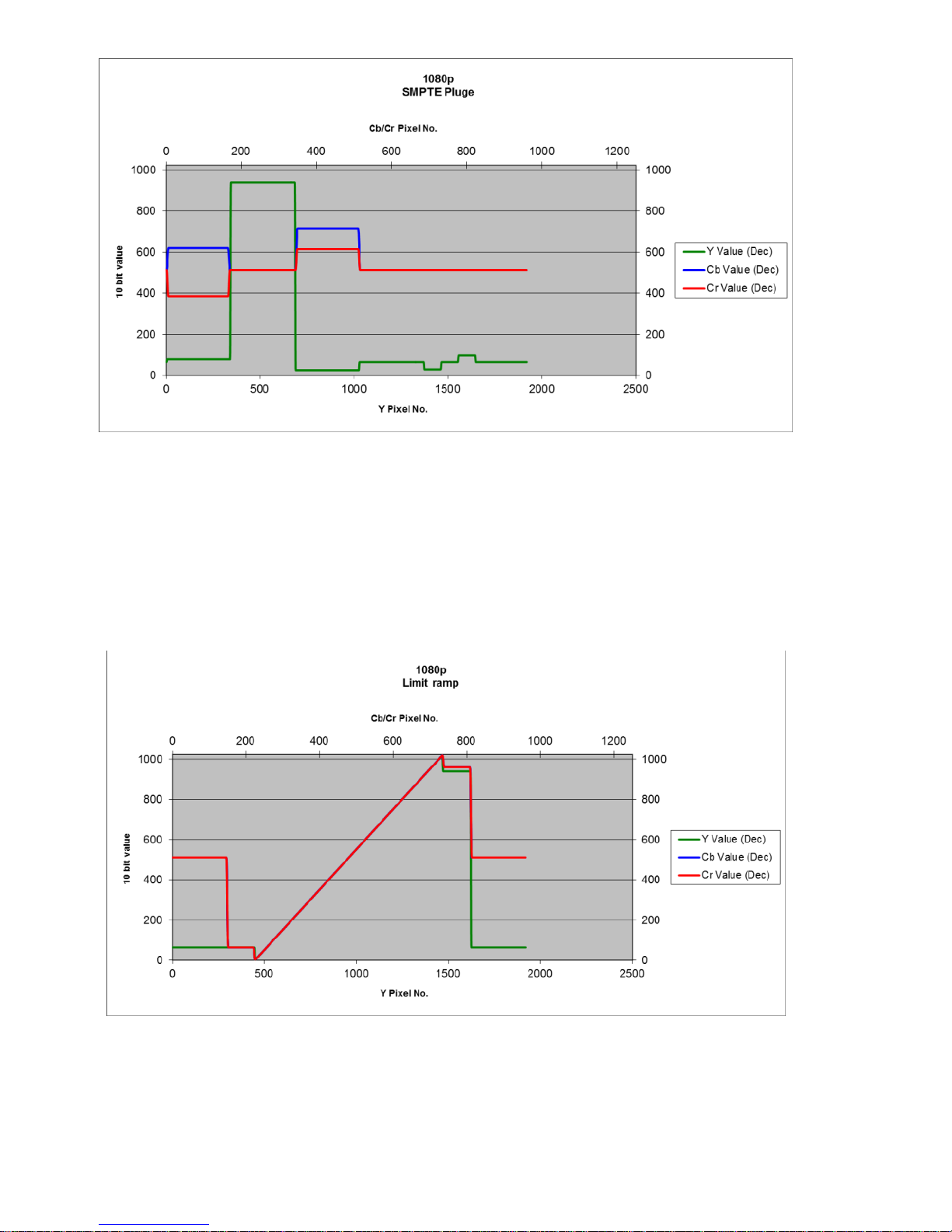
contrast. Below this is a below black ‘pluge’ which is used to set the monitor
black level.
Page 23
23
Figure 10 SMPTE Colour Bar component waveform.
Figure 11 SMPTE Reverse colour bars waveform.
Page 24
24
Figure 12 SMPTE Pluge waveform.
Ramp
This waveform is a linear modulated ramp and may be used to measure
linearity or signal to noise ratio.
Figure 13 Limit ramp waveform.
Page 25
25
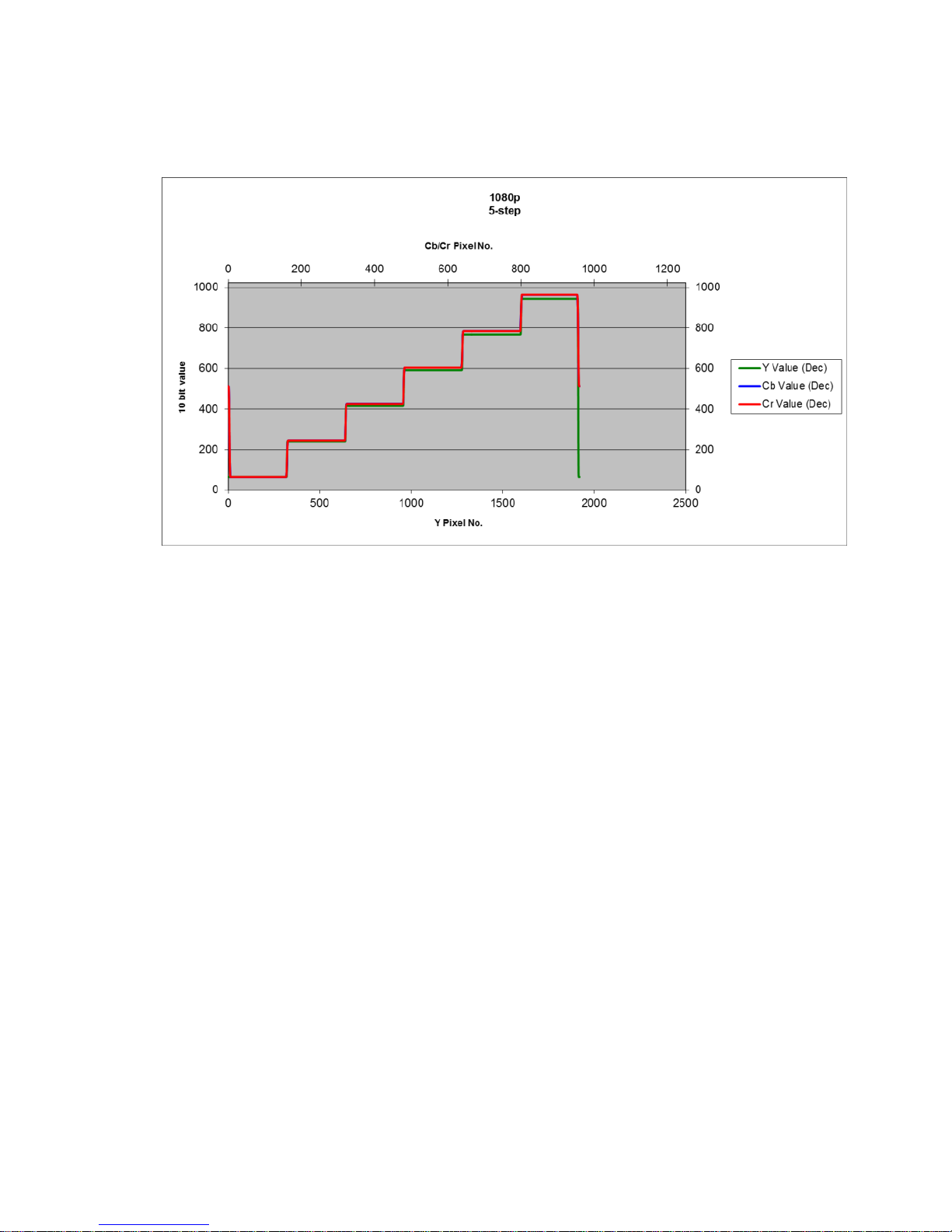
5-step staircase
This waveform is five, equal amplitude, steps of luma and chroma and may
be used to measure linearity.
Figure 14 10-step waveform.
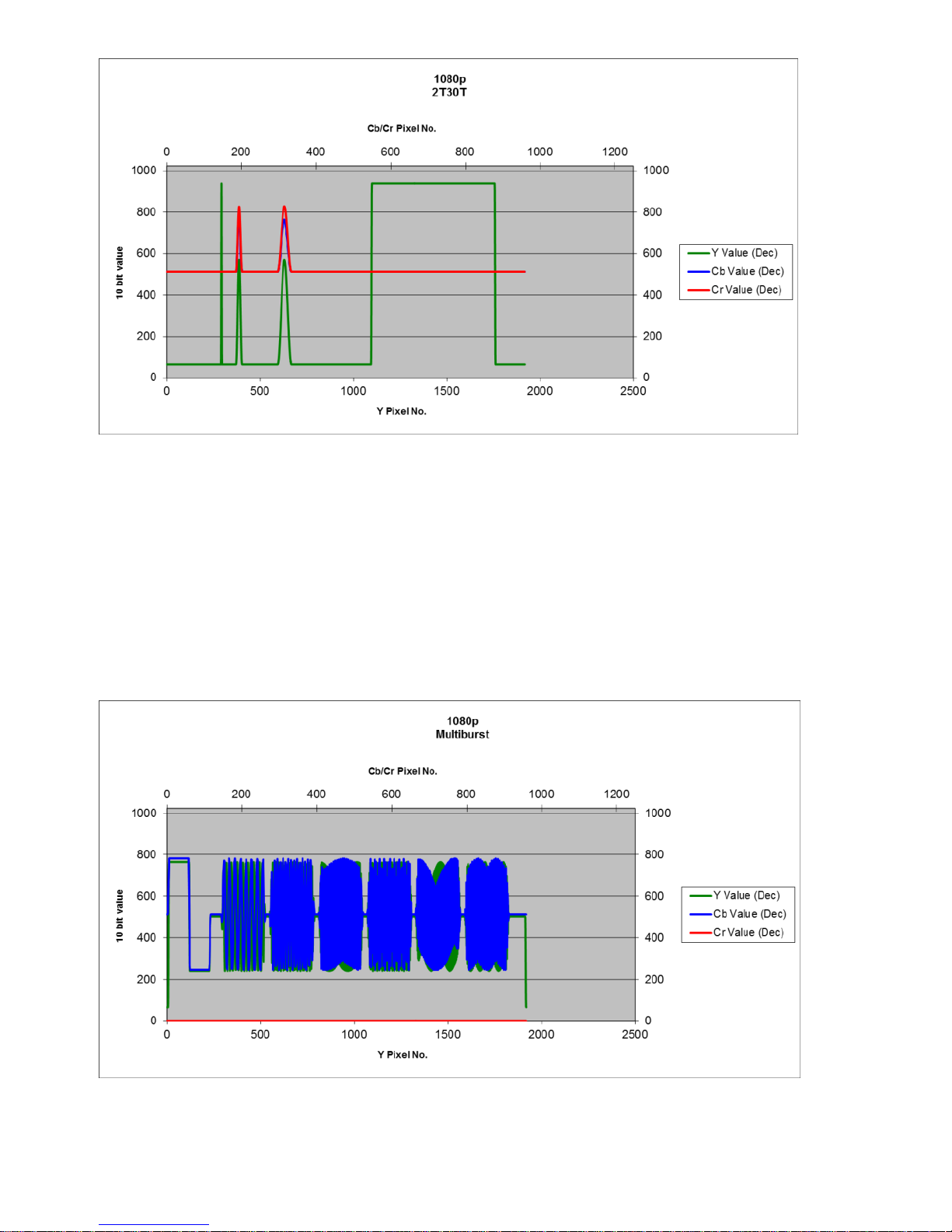
2T30T
This waveform is a pulse/bar waveform consisting of a 2T wide pulse, a
12.5T wide pulse, a 30T wide pulse and a white bar. This test signal is used
to measure the pulse response of the video path where ringing of pulses, or
asymmetry indicate possible problems. 2T is the minimum pulse width
permissible in the HD video stream.
Page 26
26
Figure 15 2T30T pulse waveform.
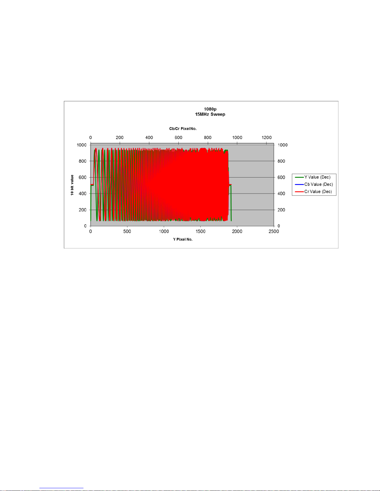
Multiburst
The Multiburst waveform is used to measure frequency response. It
consists of a reference amplitude bar and six packets of 5MHz, 10MHz,
15MHz, 20MHz, 25MHz and 30MHz for the luma channel and 2.5MHz,
5MHz, 7.5MHz, 10MHz, 12.5MHz and 15MHz for the chroma channels.
Figure 16 Multiburst waveform.
Page 27
27
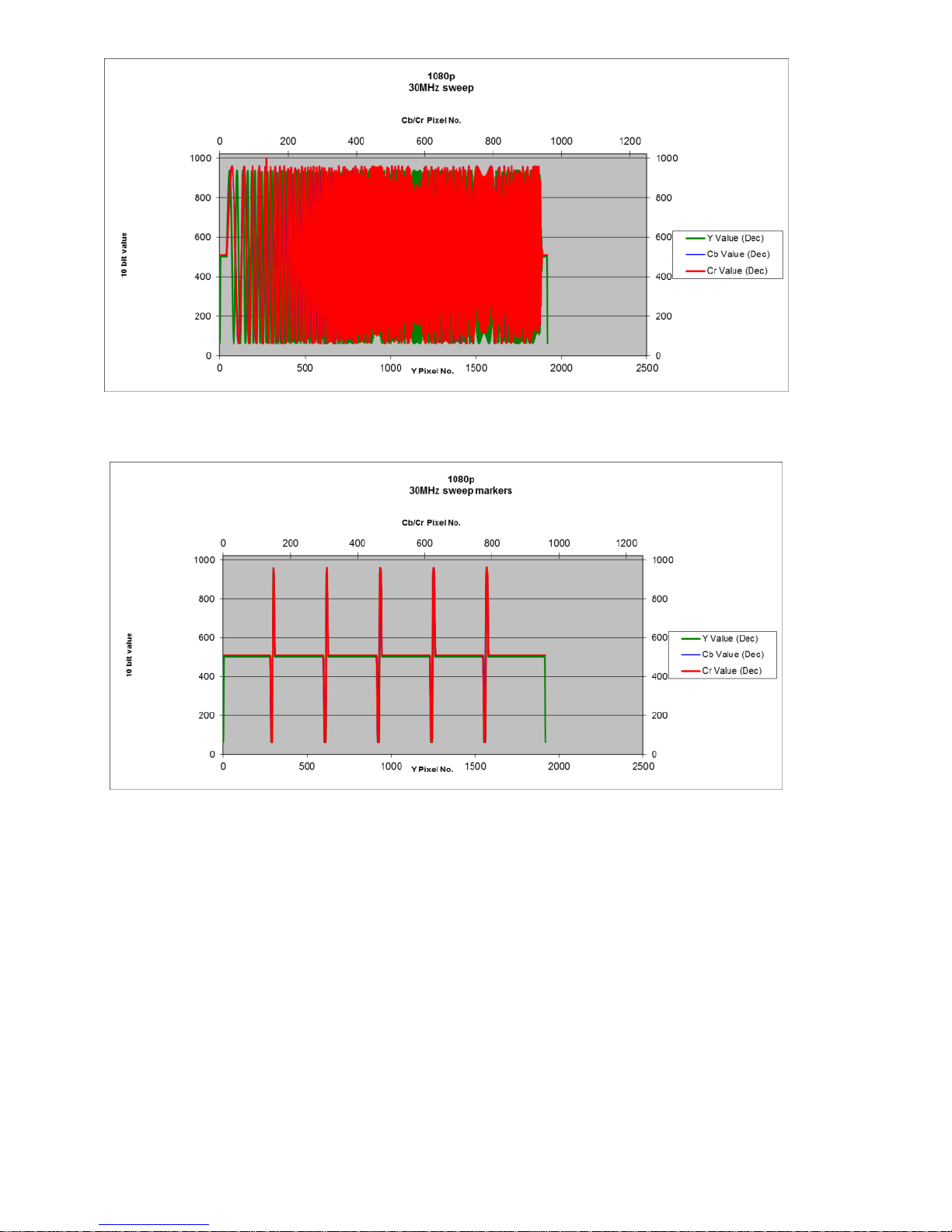
15MHzSw
This waveform is a 1MHz to 15MHz frequency sweep for the luma channel,
and a 0.5MHz to 7.5MHz frequency sweep for the chroma channels.
Figure 17 15MHz frequency sweep waveform.
30MHzSw
This waveform is a 1MHz to 30MHz frequency sweep for the luma channel,
and a 0.5MHz to 15MHz frequency sweep for the chroma channels. These
frequencies are the limits of the SMPTE-296M specification for HD video.
At the bottom of the waveform are 5 markers which indicate the
5MHz,10MHz,15MHz, 20MHz and 25MHz frequencies for luma and the
2.5MHz, 5MHz, 7.5MHz, 10MHz and 12.5MHz frequencies for chroma.
Page 28
28
Figure 18 30MHz sweep waveform.
Figure 19 30MHz sweep markers.
Black
Black is a full frame 0mV luma only video signal that may be used for noise
measurements.
White
White is a full frame 700mV luma only video signal that may be used for
noise measurements or for finding AC coupling or clamping issues.
Page 29

29
50%Grey
Pedestal is a full frame 350mV luma only video signal that may be used for
noise measurements.
Red
Red is a full frame 75% saturated red video signal.
Green
Green is a full frame 75% saturated green video signal.
Blue
Blue is a full frame 75% saturated blue video signal.
Xhatch
The crosshatch pattern is a grid of 23 x 11 (1080 line) or 21 x 11 (720 line)
lines which may be used for monitor alignment and positioning.
SDI PLL
The SDI PLL test signal is intended to test the HD-SDI input receiver.
The top half consists of a repetitive active line pattern of values Y=198h and
C=300h. After scrambling this results in either 19 ‘ones’ followed by one
‘zero’ or 19 ‘zeros’ followed by one ‘one’. This output stresses the equalizer
because of its low frequency content.
The bottom half consists of a repetitive active line pattern of values Y=110h
and C=200h. This results in an output with 20 ‘zeros’ followed by 20 ‘ones’.
This bit pattern tests the receiver PLL because of the low transition
frequency of edges in the data.
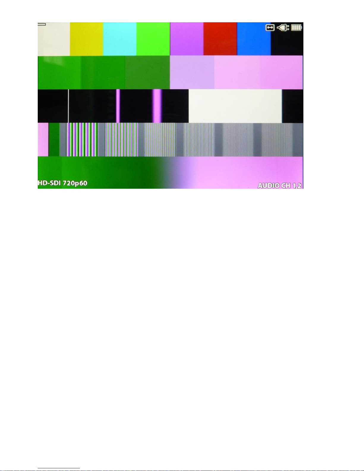
Matrix
The matrix test signal comprises five equally spaced patterns in one
combination test signal that permits a single test signal analysis of a video
component or system. The five signals are: 75% colour bars, 5 step
modulated staircase, 2T/20T pulse and bar, luma multi-burst and modulated
ramp.
Page 30
30
Figure 20 Matrix test signal.
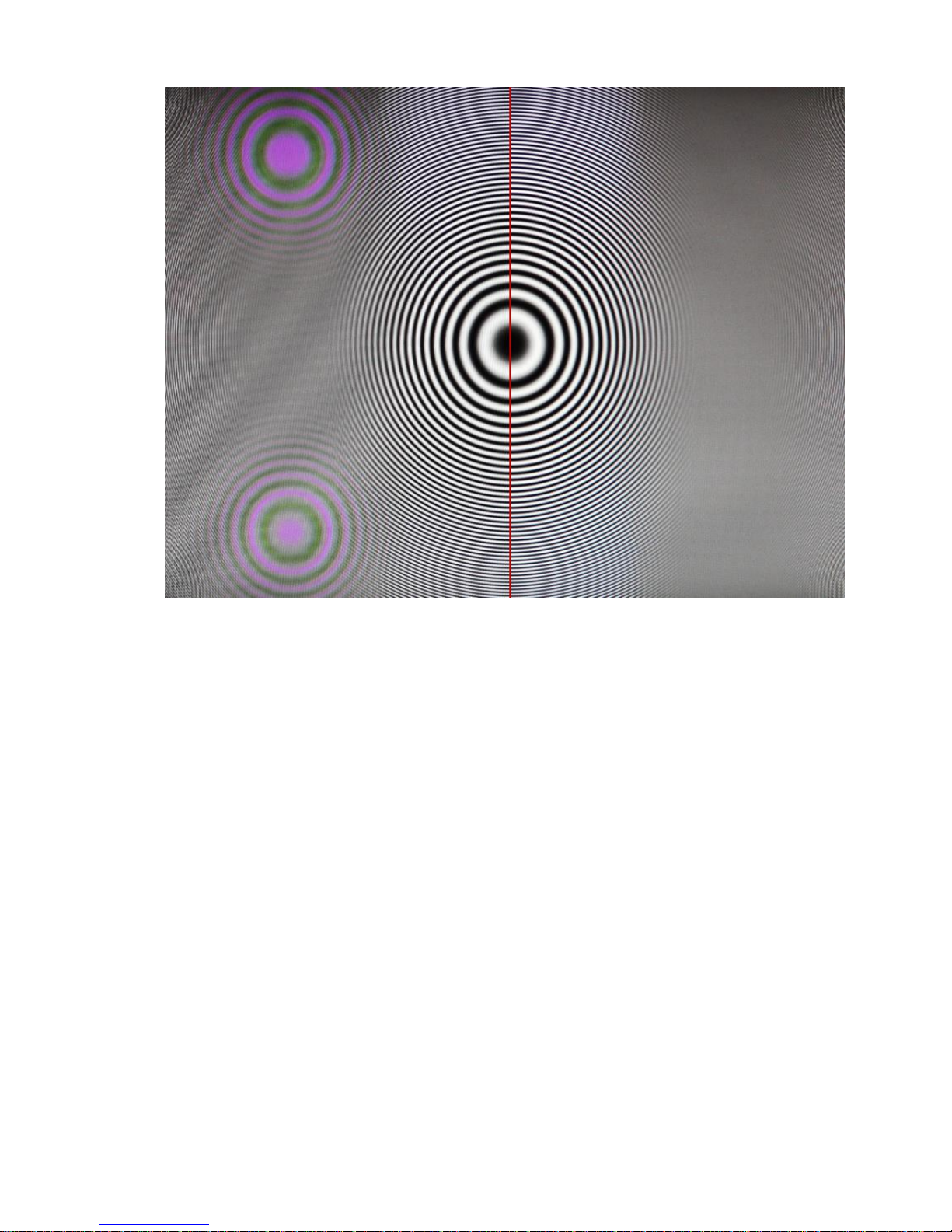
Zone Plate
The zone plate is a two-dimensional linear frequency sweep with the
highest frequencies at the edges of the image. It can be used to measure
the horizontal and vertical frequency response of system. Attenuation on
the left and right edges of the image show low pass filtering of the image;
attenuation of the top and bottom of the image show vertical filtering,
perhaps line to line averaging or issues with a scaler or de-interlacer.
The zone plate is very useful for designing and testing composite analogue
video decoders, including the new HD composite standards (see Figure 7).
The zone plate’s use is not just restricted to analogue video decoding. Any
video processing, SD or HD, which manipulates the image spatially and/or
temporally can be tested to breaking point with the zone plate: such
processing includes video standards conversion, de-interlacing and scaling.
Page 31
31
Figure 21 . Left side: The zone plate shows flickering colours at the
subcarrier frequency because of crosstalk between the luma and the
chroma. Right side: No crosstalk issues.
Page 32
32
5. SM02 Noise generator
SM02 has two noise generators that can add noise to the CVBS output.
The first of these uses a pseudo-random number generator to create white
noise. A programmable amount of this noise is added to the luma
component of the composite output. The noise can be added to the entire
video signal (including the sync and blanking) or just to the active video.
The maximum noise setting adds approximately 50dB of noise to the signal.
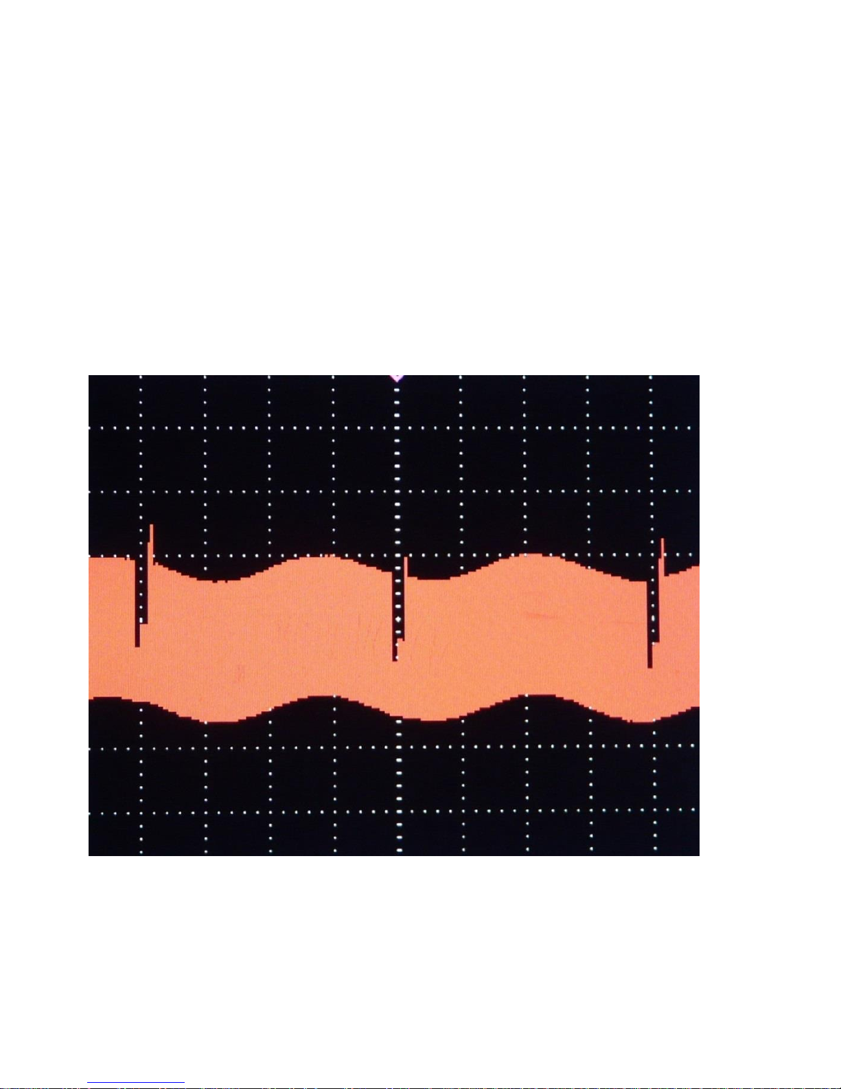
The second noise generator is a programmable frequency (50Hz or 60Hz)
hum generator. Figure 22 shows the hum generator on the aCVi output
across a frame of video.
Figure 22 Hum generator.
Page 33
33
6. aCVi Data transfer protocol
The aCVi interface allows for the bi-directional transmission of control data
between the transmitter and receiver. The data is transferred during to two
dedicated lines of the vertical blanking interval, one for transmitter to
receiver transmission, the other for receiver to transmitter.
One byte of data is sent for each line, allowing a maximum of 60 bytes to be
transferred each second, (for a 60Hz frame rate).
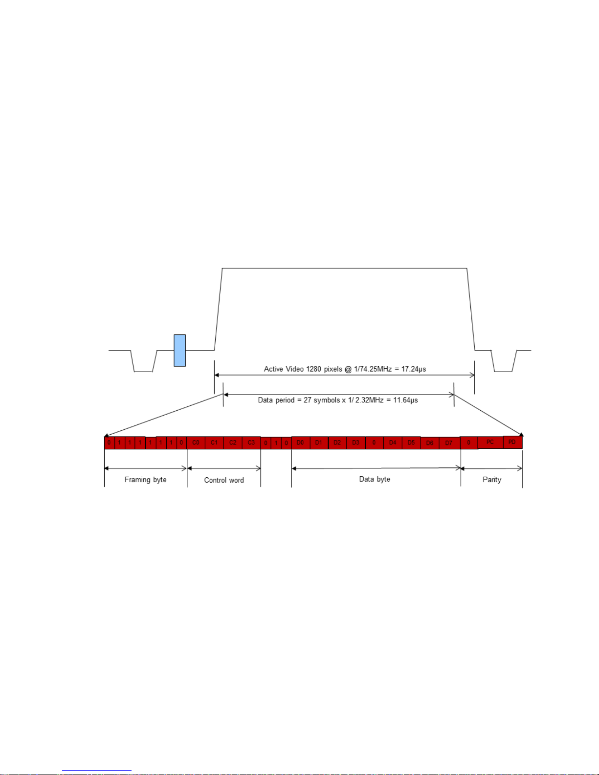
The format of the data transfer is shown in Figure 23.
Figure 23 aCVi Data format.
The format is the same regardless of the direction of transfer.
The first 8 bits are the framing byte which is a unique code signifying the
beginning of data. The receiving device must monitor the pre-defined
vertical blanking line for this framing byte which is a unique code.
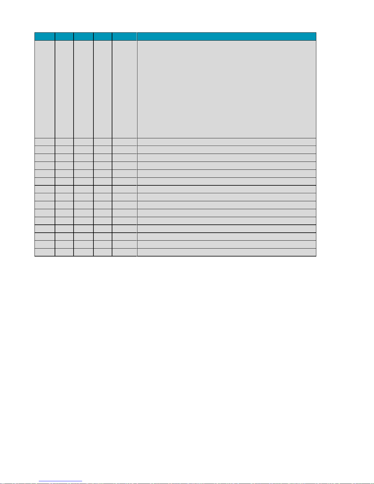
The next four bits are a control word which defines the function of the
following data byte. The control words between transmitter and receiver are
shown in Table 6.
Page 34
34
C3
C2
C1
C0
Dec
Function
0 0 0 0 0
Video standard
0 = 720p25
1 = 720p30
2 = 720p50
3 = 720p59
4 = 720p60
5 = 1080p24
6 = 1080p25
7 = 1080p29
8 = 1080p30
9 = 1080i50
10 = 1080i59
11 = 1080i60
0 0 0 1 1
User defined.
0 0 1 0 2
User defined.
0 0 1 1 3
User defined.
0 1 0 0 4
User defined.
0 1 0 1 5
User defined.
0 1 1 0 6
User defined.
0 1 1 1 7
User defined.
1 0 0 0 8
User defined.
1 0 0 1 9
User defined.
1 0 1 0 10
User defined.
1 0 1 1 11
User defined.
1 1 0 0 12
User defined.
1 1 0 1 13
User defined.
1 1 1 0 14
User defined.
1 1 1 1 15
Interface test
Table 6 aCVi Control words Transmitter > Receiver
The next three bits must be a 010 sequence (to ensure the uniqueness of
the framing byte). The next 9 bits are the data for that control function. This
is an 8-bit byte with any value between 0 and 255. The data byte is
separated into ‘nibbles’ each of 4 bits, separated by a ‘0’, again to ensure
the uniqueness of the framing byte.
The last two bits are parity bits, one for the control word and one for the
data word. The parity bits are both even parity.
The total length of the data sequence is 27 bits. Each symbol (bit) is 32 x
1/74.25MHz long = 430ns. The low bit rate ensures that the data is received
over long cable lengths even if the pre-emphasis is incorrectly set, (the
symbol length equates to a 2.23MHz data rate, which is attenuated
<2dB/100m of cable).
Page 35

35
The total data sequence length is just under 12µs and it should be
positioned centrally in the active video period, although the exact position is
not important.
The pre-defined video lines used for the transfer of data are the same for all
standards. Data is transmitted between transmitter to receiver on Line 7
and between receiver and transmitter on line 8.
Page 36
36
Appendix A: Power supply specification
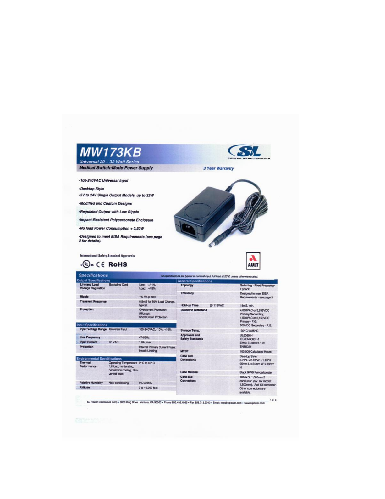
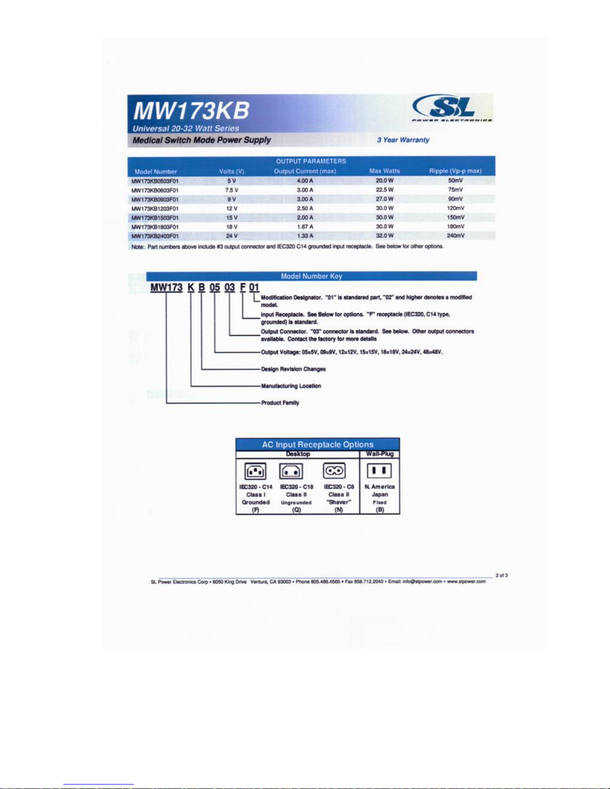
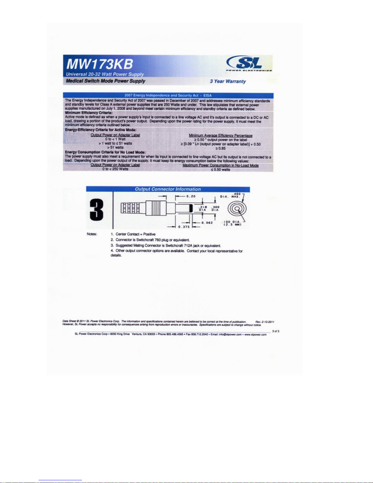
The AC-DC converter supplied with the SM02 is a model MW173KB from
SL Power Electronics Corporation. It accepts all AC inputs from 100240VAC and provides a 9V, 3A DC output for the SM02. The detailed
specification is shown below.
Page 37
37
Page 38
38
 Loading...