

Singer Valve 106-PG, A206-PG, 206-PG, S106-PG, S206-PG Installation, Operating And Maintenance Instruction
...Page 1
MODEL 106/206-PG POWER OPERATED GLOBE VALVE
Sizes 1/2" to 8" (106-PG) 3" to 10" (206-PG)
DESCRIPTION:
This valve is the basic component used for most Singer
Model 106/206 Automatic Valves. It is a hydraulically
operated valve.
DESCRIPTION OF OPERATION:
The valve opens when the bonnet (area above the
diaphragm) is connected to the downstream side of the
valve AND a pressure drop of 5 psi (35 kPa) is available
across the valve. The valve also opens when the
bonnet is vented to atmosphere, regardless of pressure
drop, provided that the line pressure is 5 psi (35 kPa) or
more.
The valve closes when the inlet pressure is directed to
the bonnet.
The valve can be made to modulate by varying the
bonnet pressure between inlet pressure and outlet
pressure. This is done by the pilot circuit.
In some cases the line media is unsuitable for use in
the pilot system. In these circumstances external water
pressure can be used in the pilot system. The external
pressure must be equal to or higher than the line
pressure.
If available pressure drop is less than 5 psi (35 kPa),
spring lift and external water pressure must be used
(consult factory).
Unless otherwise specified, the valve is assembled with
components suitable for water service up to 180
C). For other service conditions, contact your Singer
Valve representative.
STORAGE:
This valve must be stored indoors, away from direct
sunlight.
INSTALLATION:
Use washers under nuts when bolting valve flanges
to pipe flanges to protect the Epoxy Coating.
Control valves must be installed in a horizontal pipe
with the bonnet up. Smaller valves (6” and smaller) can
be installed in a vertical pipe if the order states the
orientation. Disassembly is difficult but not impossible in
valves installed in vertical pipe.
A stable, non-failing source of pressure is necessary to
operate a pilot operated control valve.
Installation, Operating and Maintenance Instructions
Operating fluid must be clean and free of air.
Under high velocity conditions the pressure signal,
when the pick-up point is located on the main valve
inlet, may be adversely affected. As an example, a relief
valve will operate more effectively and control more
accurately if the operating pressure and sensing
pressure is connected to the header.
Ideally, six pipe diameters of straight pipe is required on
the inlet of any control valve but
• Fully open Gate Valve can be installed on the inlet
of a valve, provided it is used as an isolating valve
and never used in partially open condition.
• A Butterfly Valve with stem horizontal can not
installed in the inlet of a control valve unless
operating pressure and sensing lines are connected
upstream of the butterfly valve, in a location that
gives true system pressure.
• A Butterfly Valve with stem vertical can be
installed in the inlet of a control valve as long as
velocity does not exceed 15 ft/sec. The butterfly
valve can not be used for throttling. If problems
develop at high flows, operating pressure and
possible sensing can be connected upstream of the
butterfly valve, in a location that gives true system
pressure.
o
F (80o
IOM 224A Page 1 of 2 June 2007
• A control valve can be installed with no straight pipe
on the inlet if the operating and sensing lines are
connected to a location that gives true system
pressure.
The connection point should be made at the pipe
centerline to avoid air pick-up at the top of the pipe.
1. It is possible that diaphragms may take a set
after shipping and storage. It is highly
recommended that Bonnet and Body Bolts or
Nuts be tightened after installation but before
pressurizing the valve. If a leak develops after
pressurizing, de-pressurize the valve and
tighten the bolts or nuts.
2. For most convenient operation and maintenance,
line isolation valves should be installed.
3. A suitable bypass should be provided to allow for
servicing of the valve without interrupting the flow.
Surrey, BC. Canada. V3W 3H9
12850-87th Avenue
Ph: 604-594-5404
Fx: 604-594-8845
www.singervalve.com
be
Page 2

Installation (Cont.):
4. Install pressure gauges upstream and/or
downstream of valve as appropriate. This will
facilitate ease of setting the pilot system.
5. A strainer with a suitable basket should be installed
ahead of the valve to protect it from foreign
material.
6. Sufficient space should be provided around the
valve for disassembly.
7. Flush system of all foreign matter before installing
the valve.
8. Check direction of flow (inlet of valve is marked OR
an arrow on the side of body indicates flow
direction) and install the valve accordingly.
VENT AIR FROM THE BONNET. After installation,
9.
when the valve is pressurized, vent air from the
bonnet:
a) Valves installed in horizontal piping with bonnet up
(NO LIMIT SWITCH):
Sizes up to 2" where pilot connection is to the guide
bushing at the center of the valve do not require
venting (they vent automatically).
Sizes up to 2" with position indicator: use bleed-cock
on indicator.
Sizes 2-1/2" and larger, loosen pipe plug at the
center of the bonnet to bleed air. If equipped with
position indicator, use bleed-cock on indicator.
b) Valves installed in horizontal piping with bonnet up
(WITH LIMIT SWITCH): Refer to Drawing A0707A.
Use bleed screw (63) to vent air.
c) Valves installed in vertical pipe: The pilot connection
will be to the highest point on the bonnet if the
orientation and flow direction were specified on the
order. Some sizes vent automatically. Some sizes
are provided with a small screw to facilitate bleeding
(do not remove completely).
d) Valves that do not have the bleed screw and do not
bleed completely from existing connections must be
bled by loosening the bonnet bolts.
SERVICE SUGGESTIONS:
POSSIBLE CAUSE / REMEDY
FAILS TO OPEN
1. Insufficient inlet pressure. / Increase pressure
IOM 224A Page 2 of 2 June 2007
Surrey, BC. Canada. V3W 3H9
2. Pressure in the bonnet is not released:
• Isolating valves on pilot lines closed. - Open valves
12850-87th Avenue
Ph: 604-594-5404
Fx: 604-594-8845
www.singervalve.com
• Pilot components not functioning. - Refer to specific
instructions on pilot components
• Foreign material in pilot system. - Clear obstruction
FAILS TO CLOSE
Lack of pressure in the bonnet due to:
• Pilot components not functioning. - Refer to specific
instructions on pilot components.
• Foreign material in pilot system.
• Ruptured diaphragm.
• Obstruction in the valve.
• Worn main valve disc.
PULSATIONS
• Air in the bonnet. - Vent air. Refer to "Installation
(9)" above.
• Improper adjustment to pilot components. - Refer to
specific instructions on pilot components.
• Valve oversized. A smaller valve in parallel may be
required.
MAINTENANCE:
The SINGER Model 106/206-PG requires a minimum of
maintenance. All parts are accessible for inspection
and repair without removing the valve from the line.
1. Close upstream and downstream isolating gate
valves.
2. Disconnect body and bonnet pilot lines.
3. Remove bonnet. If bonnet does not come free
readily, it can be pried loose with a small pry-bar.
4. Remove main valve assembly for inspection. Do
not remove seat ring unless inspection shows that it
is damaged.
5. Replace worn or defective parts and reassemble.
NOTE REGARDING FREEZING:
This valve does not drain completely when inlet and
outlet pipes are drained. Where freezing conditions are
expected, one of the following must be performed:
• Drain valve and pilot system completely.
• Add suitable anti-freeze to valve and pilot system
(Non-potable water service only).
• Provide insulation and/or heating to keep the valve
from freezing.
Page 3
Page 4

Material Specifications & Dimensions
Item
Part Name Material Item Part Name Material
1 Body Ductile Iron
2 Bonnet Ductile Iron
3 Seat Ring Stainless Steel
4 Stem Stainless Steel
5 Disc Retainer Brass on 3” & 4”
6 ** Resilient Disc EPDM or Buna-N
7 Inner Valve Cast Iron
8 ** Diaphragm EPDM or Buna-N
9 Clamp Plate Cast Iron
10 Stem Nut Brass
11 Spring Stainless Steel
12 Guide Bushing Brass
13 Stem Cap Ductile Iron
14 ** Seat Ring Seal Buna-N
15 ** Stem Cap Seal Buna-N
Bronze on 6”
Cast Iron on 8” and 10”
206-PG & A206-PG
3”
4”
6”
8”
10”
150F / PN16
150F / PN10, PN16,
PN25, PN40
300F
150F / PN10, PN16
300F / PN25, PN40
150F / PN10, PN16
300F / PN25, PN40
150F / PN10, PN16
300F / PN25, PN40
80mm
100mm
150mm
200mm
250mm
A D E C B E F
12”
305mm
15”
381mm
15.63”
397mm
20.12”
511”
21”
533mm
25”
635mm
26”
660mm
24.50”
622mm
25.88”
657mm
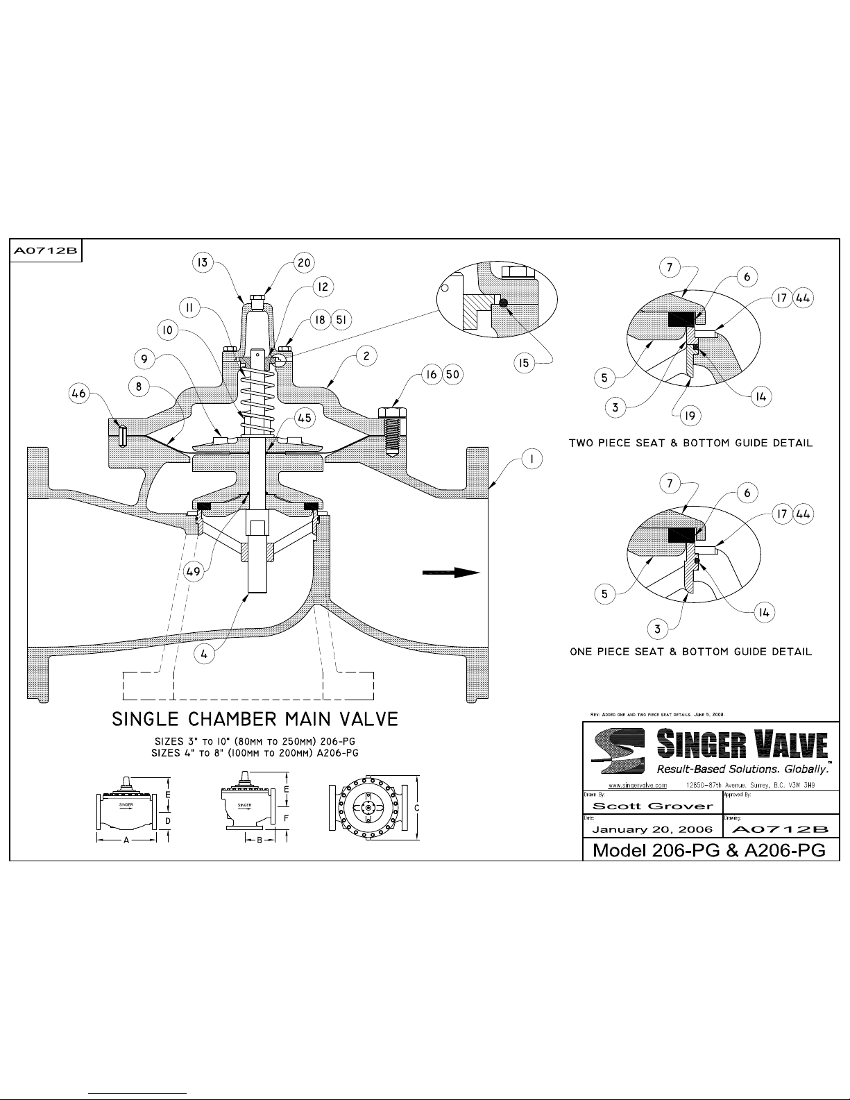
3” to 10” (80mm to 250mm) 206-PG
4” to 8” (100mm to 200mm) A206-PG
For Drawing A0712B
Globe Globe & Ang Angle
4”
102mm
4.60”
117mm
5”
127mm
5.50”
140mm
6.25”
159mm
6.75”
171mm
7.50”
191mm
8”
203mm
8.63”
219mm
16 Body Capscrew Stainless Steel
17 % Seat Ring Screw Stainless Steel
18 Stem Cap Capscrew Stainless Steel
19 Φ Bottom Guide Ductile Iron & Bronze
44 % Retaining Washer Stainless Steel
45 ** Diaphragm Seal Buna-N
46 Locating Pin Steel
49 ** Disc Retainer Seal Buna-N
50 Body Washer Stainless Steel
51 Stem Cap washer Stainless Steel
** Recommended spare parts (included in the Rebuild Kit)
Φ Bottom guide includes bronze bearing bushing
% Not required on size 3”, (One piece seat ring and guide, shown as item 3)
7.50”
191mm
9.62”
244mm
9.62”
244mm
10.50”
267mm
10.50”
267mm
14.12”
359mm
14.12”
359mm
18.63”
473mm
18.63”
473mm
8.19”
208mm
10”
254mm
10”
254mm
12.50”
318mm
12.50”
318mm
16”
406mm
16”
406mm
20”
508mm
20”
508mm
- - -
7.56”
192mm
7.88”
200mm
10.19”
259mm
10.63”
270mm
12.50”
318mm
13”
330mm
- - -
- - -
Surrey, BC. Canada. V3W 3H9
7.75”
197mm
7.75”
197mm
8.82”
224mm
8.82”
224mm
11.30”
287mm
11.30”
287mm
12850-87th Avenue
Ph: 604-594-5404
Fx: 604-594-8845
www.singervalve.com
5.94”
151mm
6.25”
159mm
6.19”
157mm
6.81”
173mm
9”
229mm
9.50”
241mm
Anti-Cavitation (-AC) trim equipped valves are NOT available in Reduced Port 206-PG Valves.
April 2006
Page 5

MODEL S106/S206-PG POWER OPERATED GLOBE VALVE
Sizes 6” to 16" (S106-PG) 12” to 24" (S206-PG)
Installation, Operating and Maintenance Instructions
DESCRIPTION:
This valve is the basic component used for most
Singer Automatic Valves. It is a hydraulically
operated valve.
DESCRIPTION OF OPERATION:
The valve opens when the bonnet (area above the
diaphragm) is connected to the downstream side of
the valve AND a pressure drop of 5 psi (35 kPa) is
available across the valve. The valve also opens
when the bonnet is vented to atmosphere, regardless
of pressure drop, provided that the line pressure is 5
psi (35 kPa) or more.
The valve closes when the inlet pressure is directed to
the bonnet.
The valve can be made to modulate by varying the
bonnet pressure between inlet pressure and outlet
pressure. This is done by the pilot circuit.
In some cases the line media is unsuitable for use in
the pilot system. In these circumstances external
water pressure can be used in the pilot system. The
external pressure must be equal to or higher than the
line pressure.
Unless otherwise specified, the valve is assembled
with components suitable for water service up to
o
180
F (80o C). For other service conditions, contact
your Singer Valve representative.
STORAGE:
This valve must be stored indoors, away from
direct sunlight.
INSTALLATION:
Use washers under nuts when bolting valve
flanges to pipe flanges to protect the Epoxy
Coating.
Control valves must be installed in a horizontal pipe
with the bonnet up. Smaller valves (6” and smaller)
can be installed in a vertical pipe if the order states
the orientation. Disassembly is difficult but not
impossible in valves installed in vertical pipe.
A stable, non-failing source of pressure is necessary
to operate a pilot operated control valve.
IOM 224C Page 1 of 2 August 2007
Surrey, BC. Canada. V3W 3H9
Operating fluid must be clean and free of air.
12850-87th Avenue
Ph: 604-594-5404
Fx: 604-594-8845
www.singervalve.com
Under high velocity conditions the pressure signal,
when the pick-up point is located on the main valve
inlet, may be adversely affected. As an example, a
relief valve will operate more effectively and control
more accurately if the operating pressure and sensing
pressure is connected to the header.
Ideally, six pipe diameters of straight pipe is required
on the inlet of any control valve but
• Fully open Gate Valve can be installed on the
inlet of a valve, provided it is used as an isolating
valve and never used in partially open condition.
• A Butterfly Valve with stem horizontal can not
be
installed in the inlet of a control valve unless
operating pressure and sensing lines are
connected upstream of the butterfly valve, in a
location that gives true system pressure.
• A Butterfly Valve with stem vertical can be
installed in the inlet of a control valve as long as
velocity does not exceed 15 ft/sec. The butterfly
valve can not be used for throttling. If problems
develop at high flows, operating pressure and
possible sensing can be connected upstream of
the butterfly valve, in a location that gives true
system pressure.
• A control valve can be installed with no straight
pipe on the inlet if the operating and sensing lines
are connected to a location that gives true system
pressure.
The connection point should be made at the pipe
centerline to avoid air pick-up at the top of the pipe.
1. It is possible that diaphragms may take a set
after shipping and storage. It is highly
recommended that Bonnet and Body Bolts or
Nuts be tightened after installation but before
pressurizing the valve. If a leak develops after
pressurizing, de-pressurize the valve and
tighten the bolts or nuts.
Revised April 28, 2010
Page 6

Installation (Cont.):
2. For most convenient operation and maintenance,
line isolation valves should be installed.
3. A suitable bypass should be provided to allow for
servicing of the valve without interrupting the flow.
4. Install pressure gauges upstream and/or
downstream of valve as appropriate. This will
facilitate ease of setting the pilot system.
5. A strainer with a suitable basket should be
installed ahead of the valve to protect it from
foreign material.
6. Sufficient space should be provided around the
valve for disassembly.
7. Flush system of all foreign matter before installing
the valve.
8. Check direction of flow (inlet of valve is marked
OR an arrow on the side of body indicates flow
direction) and install the valve accordingly.
9. VENT AIR FROM THE BONNET After ins tallation,
when the valve is pressurized, vent air from the
bonnet:
• Valves with no Limit Switch: Loosen pipe plug at
the centre of the bonnet to bleed air. If
equipped with position indicator, use bleed-cock
on indicator.
• Valves with Limit Switch: Refer to Drawing
A0707A. Use bleed screw (63) to vent air.
POSSIBLE CAUSE / REMEDY
FAILS TO OPEN
1. Insufficient inlet pressure. / Increase pressure
2. Pressure in the bonnet is not released:
• Isolating valves on pilot lines closed. - Open
valves
• Pilot components not functioning. - Refer to
specific instructions on pilot components
• Foreign material in pilot system. - Clear
obstruction
SERVICE SUGGESTIONS:
IOM 224C Page 2 of 2 August 2007
Surrey, BC. Canada. V3W 3H9
12850-87th Avenue
www.singervalve.com
FAILS TO CLOSE
Lack of pressure in the bonnet due to:
• Pilot components not functioning. - Refer to
specific instructions on pilot components.
• Foreign material in pilot system. - Clear
obstructions.
• Ruptured diaphragm. - Replace worn parts.
• Obstruction in the valve. - Remove obstructions.
• Worn main valve disc. - Replace disc.
PULSATIONS
• Air in the bonnet. - Vent air. Refer to "Installation
(9)" above.
• Improper adjustment to pilot components. - Refer
to specific instructions on pilot components.
• Valve oversized. A smaller valve in parallel may
be required.
MAINTENANCE:
The SINGER Model S106/S206-PG requires a
minimum of maintenance. All parts are accessible for
inspection and repair without removing the valve from
the line.
1. Close upstream and downstream isolating gate
valves.
2. Disconnect body and bonnet pilot lines.
3. Remove bonnet. If bonnet does not come free
readily, it can be pried loose with a small pry-bar.
4. Remove inner valve assembly for inspection. Do
not remove seat ring unless inspection shows that
it is damaged. Be very careful not to damage
the epoxy coating when removing and
installing the inner valve assembly.
5. Replace worn or defective parts and reassemble.
NOTE REGARDING FREEZING:
This valve does not drain completely when inlet and
outlet pipes are drained. Where freezing conditions
are expected, one of the following must be performed:
• Drain valve and pilot system completely.
• Add suitable anti-freeze to valve and pilot system
(Non-potable water service only).
• Provide insulation and/or heating to keep the
valve from freezing.
Ph: 604-594-5404
Fx: 604-594-8845
Revised April 28, 2010
Page 7

Page 8

Material Specifications & Dimensions
10” to 16” (250mm to 400mm) S106-PG & SA106-PG
12” to 24” (300mm to 600mm) S206-PG
For Drawing A0867C
Item
Part Name Material Item Part Name Material
1. Body Ductile Iron
2. Bonnet Ductile Iron
3. Spring Casing Ductile Iron
6. Bottom Guide Ductile Iron & Stainless Steel
7. Seat Ring Stainless Steel
8. Seat Ring Washers Stainless Steel
9. Stem Stainless Steel
10. Disc Retainer Ductile Iron
11.** Resilient Disc EPDM or Buna-N
12. Inner Valve Ductile Iron
13. Piston Ductile Iron
14. Clamp Plate Ductile Iron
15.** Diaphragm EPDM or Buna-N
16. Stem Nut Stainless Steel
17. Spring Stainless Steel
18. Bonnet Locating Pins Steel
19. Bleed Valve Stainless Steel
20.** Seat Ring Seal Buna-N
21.** Spring Casing Seal Buna-N
22.** Stem Seals Buna-N
23. Bonnet Bolts Stainless Steel
24. Bonnet Washers Stainless Steel
25. Spring Casing Locating Pins Steel
26. Spring Casing Screw Stainless Steel
27. Spring Casing Washers Stainless Steel
28. Seat Ring Screw Stainless Steel
29. Eye Bolt Steel
31. Clamp Plate Screw Stainless Steel
32. Inner Valve Screw Stainless Steel
** Recommended spare parts (included in the Rebuild Kit)
S106-PG & SA106-PG
10”
12”
14”
16”
150F / PN10, PN16
300F / PN25, PN40
150F / PN10, PN16
300F / PN25, PN40
150F / PN10, PN16
300F / PN25, PN40
150F / PN10, PN16
300F / PN25, PN40
250mm
300mm
350mm
400mm
A D E C B E F
29.75”
756mm
31.12”
790mm
34”
864mm
35.50”
902mm
31”
787mm
32.50”
826mm
41.38”
1051mm
43.50”
1105mm
Globe Globe & Ang Angle
8.56”
217mm
9.56”
243mm
9.50”
241mm
10.25”
260mm
10.50”
267mm
11.50”
292mm
11.75”
298mm
12.75”
324mm
23.31”
592mm
23.31”
592mm
26.75”
679mm
26.75”
679mm
26.80”
681mm
26.80”
681mm
31.40”
798mm
31.40”
798mm
22.13”
562mm
22.13”
562mm
26”
660mm
26”
660mm
26”
660mm
26”
660mm
32”
813mm
32”
813mm
11.50”
292mm
12.19”
310mm
13.75”
349mm
14.50”
368mm
- - -
- - -
18”
457mm
18.81”
478mm
S206-PG
12”
300mm
16”
400mm
18”
450mm
20”
500mm
24”
600mm
150F / PN10, PN16
300F / PN25, PN40
150F / PN10, PN16
300F / PN25, PN40
150F / PN10, PN16
300F / PN25, PN40
150F / PN10, PN16
300F / PN25, PN40
150F / PN10, PN16
300F / PN25, PN40
A D E C B E F
27.50”
699mm
29”
737mm
36”
914mm
37.63”
956mm
42”
1067mm
43.63”
1108mm
45”
1143mm
46.38”
1178mm
50.50”
1283mm
52.25”
1327mm
Globe Globe & Ang Angle
9.50”
241mm
10.50”
267mm
11.75”
298mm
12.75”
324mm
12.50”
318mm
14”
356mm
13.75”
349mm
15.25”
387mm
16”
406mm
18”
457mm
23.35”
593mm
23.35”
593mm
26.75”
679mm
26.75”
679mm
31.38”
797mm
31.38”
797mm
31.38”
797mm
31.38”
797mm
31.38”
797mm
31.38”
797mm
22.12”
562mm
22.12”
562mm
26”
660mm
26”
660mm
30.31”
770mm
30.31”
770mm
30.50”
775mm
30.50”
775mm
36”
914mm
36”
914mm
- - -
- - -
- - -
- - -
- - -
- - -
- - -
- - -
- - -
- - -
Surrey, BC. Canada. V3W 3H9
20”
508mm
20”
508mm
23.75”
603mm
23.75”
603mm
28.50”
724mm
28.50”
724mm
12850-87th Avenue
Ph: 604-594-5404
Fx: 604-594-8845
www.singervalve.com
12.50”
318mm
13.19”
335mm
12.50”
318mm
13.25”
337mm
15.69”
399mm
16.50”
419mm
For Anti-Cavitation (-AC) trim equipped valves please see PG-AC spec sheet January 2006
 Loading...