

Singer Valve 106-RPS-RR, 206-RPS-RR Installation, Operating And Maintenance Instruction

SINGER MODEL 106/206-RPS-RR
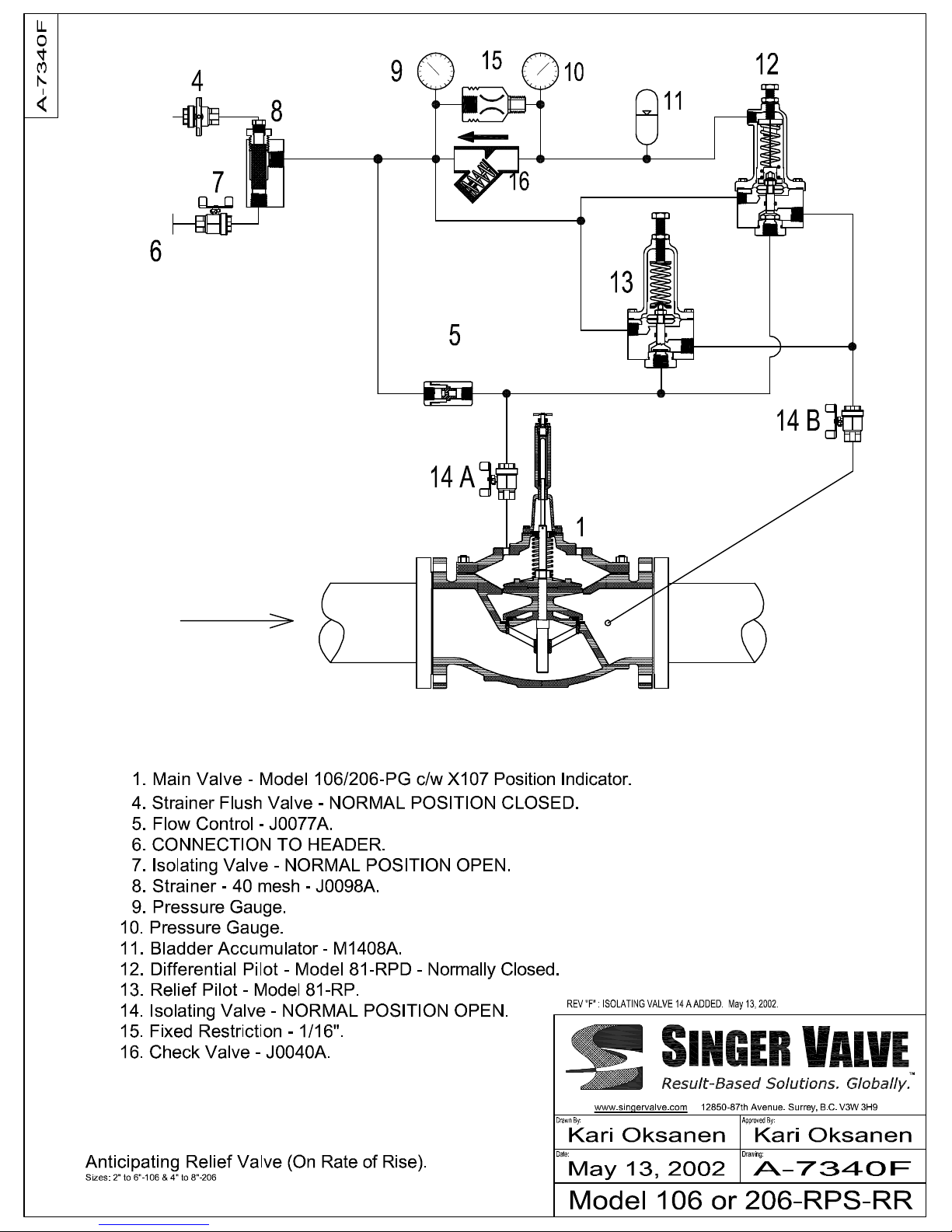
Anticipating Relief Valve (on Rate of Rise)
Installation, Operating and Maintenance Instructions
Up to 6” 106/8” 206 Schematic A-7340F 8” 106/10” 206 & larger Schematic A-7340F1
DESCRIPTION:
Model 106/206-RPS-RR is an anticipating relief valve
designed to dissipate surges caused by power failure or other
sudden stoppage of a pump.
The valve opens when the header pressure rises faster than
a rate determined by the pilot system. The valve also opens
if the header pressure reaches the setpoint of Relief Pilot
(13).
MODEL 106/206-RPS-RR:
• Anticipates the surge by opening as soon as the
pressure starts to rise.
• Closes after the surge has been dissipated and the
header pressure is stable.
• Handles initial filling of the system automatically.
• Is not affected by over sizing the way standard
anticipating surge valves are.
DESCRIPTION OF OPERATION:
Main Valve (1) closes when BOTH Pilot (12) and Pilot (13)
are closed. The Main Valve opens when EITHER Pilot (12)
or Pilot (13) opens. On larger valves (Schematic A7340F1), Pilot (12) acts through a Booster Valve (18) to
increase opening speed.
When the header pressure increases slowly, the two
pressures sensed by Pilot (12) remain equal and Pilot (12)
remains closed. When the header pressure increases
rapidly, the pressure in the spring casing (above the
diaphragm) of Pilot (12) lags behind the pressure below the
diaphragm. Pilot (12) opens. The rate of pressure rise
required to open Pilot (12) depends on Accumulator (11) and
the size of Fixed Restriction (15).
For Schematic A-7340F, Pilot (12) opens the Main Valve
(1) as soon as the header pressure starts increasing after a
power failure (pump stoppage). This gives the Main Valve
sufficient time to be fully open before the pressure rises to
destructive levels.
For schematic A-7340F1, Pilot (12) operates the Main
Valve by opening Booster Valve (18). When Booster Valve
(18) opens, the Main Valve opens. When Booster Valve (18)
closes, the Main Valve closes.
Pilot (13) opens the Main Valve if the header pressure
reaches the set point of Pilot (13).
INSTALLATION:
Model 106/206-RPS-RR is installed on a "Tee" from the main
line (header) into atmosphere.
1. Refer to 106/206-PG "installation". Bypass and strainer
are normally not used.
2. Model 106/206-RPS-RR operates under conditions which
cause very high velocities and severe cavitation. These
conditions may cause considerable vibration. The
supports for the valve must be designed accordingly.
IOM A-7340F Page 1 of 1 July 2005
Surrey, BC. Canada. V3W 3H9
3. CONNECT PILOT SENSING (6) TO THE HEADER.
4. Open isolating valves (7), (14 A) and (14 B).
ADJUSTMENT AND TEST PROCEDURE:
1. Setting of Pilot (12) and pre-charge of Accumulator (11)
should not be changed without a clear understanding of
the consequences. These are factory set and should not
require adjustment.
2. Relief Pilot (13) can be set approximately by removing
the tubing from the outlet of Pilot (13) and observing Pilot
(13) under maximum pumping pressure. Pilot (13) should
be set about one turn of the adjusting screw higher than
the point where it starts leaking.
3. If a more exact pressure setting is required, a hydrostat
pump or other source of pressure should be connected to
the sensing line of Pilot (13).
4. To test Accumulator (11), Check Valve (16) and Fixed
Restriction (15):
a) Close Isolating Valve (14 B).
b) Close Isolating Valve (7).
c) Open Strainer Flush Valve (4). Water should flow for
one or two seconds and should then stop suddenly.
There should not be any appearance of air in the flow.
d) Close Strainer Flush Valve (4).
e) Observe Pressure Gauges (9) and (10) and open
Isolating Valve (7). Gauge (9) should jump to line
pressure immediately but Gauge (10) should rise slowly
and steadily over several seconds. The rate at which
Gauge (10) rises is the rate of pressure rise that triggers
Pilot (12).
If it is desired to test Differential Pilot (12) and Main Valve
(1), repeat above procedure with Isolating Valve (14 B) open.
Main Valve (1) should open fast and close slowly after the
pressure readings in Gauges (9) and (10) have equalized.
NOTE: DO NOT ADJUST PILOT (12) TO ADJUST THE
RATE OF RISE SETTING. If a different rate is required,
Fixed Restriction (15) must be changed.
If the closing speed of Main Valve (1) needs adjustment,
insert of Flow Control (5) must be changed.
Accumulator loading should be approximately 20% of the
maximum pumping pressure. This loading can be tested IF
REQUIRED at the fitting on top of Accumulator (11). The
loading should not be checked too frequently, as some
nitrogen will be lost on each test. Only nitrogen should be
used for charging the accumulator.
After testing, check to make sure that Isolating Valves are in
the proper position:
• Valves 7, 14 A and 14 B - OPEN
• Valve 4 - CLOSED
12850-87th Avenue
Ph: 604-594-5404
Fx: 604-594-8845
www.singervalve.com
 Loading...