

Singer Valve 106-EF-8837BX, 206-EF-8837BX Installation, Operating And Maintenance Instructions
Model 106/206-EF-8837BX
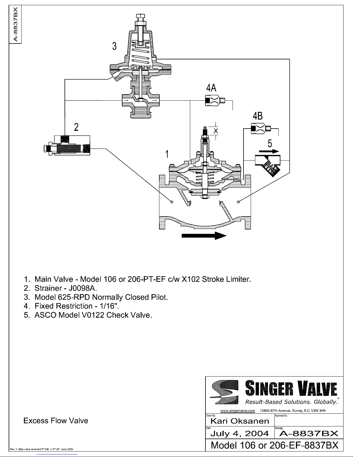
EXCESS FLOW VALVE
Schematic A-8837BX
DESCRIPTION:
Model 106/206-EF-8837BX is normally open
an adjustable amount. The valve senses the
pressure drop across itself and closes when
the pressure drop reaches a pre-set value
(typically 5 psi). Once closed, the valve
requires a minimum inlet pressure of 10 psi to
remain closed until re-set by equalizing the
pressure on both sides of the valve. Since the
pressure drop on a partially open valve is
related to the flow through the valve, the
valve trips (closes) at a pre-determined flow.
DESCRIPTION OF OPERATION:
Main Valve (1) is held partially open by a
spring under the diaphragm, a Stroke Limiting
Screw and by the inlet pressure acting on the
unbalanced area of the stem.
Normally Closed Pilot (3) senses the
pressure differential between the inlet and
the outlet of Main Valve (1). When this
pressure differential reaches the set-point of
Pilot (3), Pilot (3) opens. The inlet pressure of
Main Valve (1) is connected to the bonnet of
the Main Valve to close the valve. Closing is
positive even with low inlet pressure because
the underside of the diaphragm is at
atmospheric pressure.
Check Valve (5) assures that the valve closes
and remains closed in installations where the
outlet pipe runs downhill. There will be
continuous flow through Fixed Restriction
(4A) to drain as long as Pilot (3) is open. This
acts as an indication of tripping conditions
and also makes the valve operation more
predictable because the Main Valve closes at
a positive flow through Pilot (3), not at a nonpredictable leakage.
IOM A-8837BX Page 1 of 1 February 2007
Surrey, BC. Canada. V3W 3H9
12850-87th Avenue
Ph: 604-594-5404
Fx: 604-594-8845
www.singervalve.com
INSTALLATION:
See 106/206-PT-EF ‘Installation’.
START-UP AND ADJUSTMENT:
To check operation of the valve and the flow
at which the valve trips, a high flow must be
generated and some means of measuring the
flow must be available.
This valve closes fast. Observe inlet surge
caused by valve closing. Closing surge is
proportional to flow change. Start by closing
from low flow. If closing surge is too high,
install a Closing Speed Restrictor.
When the flow increases, the pressure drop
on the Main Valve increases exponentially.
When the pressure drop reaches the set
point of Pilot (3), the Pilot opens. There will
be flow to drain from Fixed Restriction (4) and
the Main Valve will close.
Pilot (3) can be adjusted to trip at a pressure
drop from 3 psi to 8 psi. Any attempt to set
the pilot outside of this range will result in
unreliable operation.
Important Safety Notice:
X102 Stroke Limiter is limited in the safe
pressure drop that it can handle. Make sure
that under no circumstance will the
pressure drop exceed the rating of the
X102 Stroke Limiter. This means that the
X102 Stroke Limiter will not be used to close
the valve past the point where the maximum
pressure drop caused by the valve at
maximum flow is higher than the rating of the
X102 of that particular size.
 Loading...