

Page 1
SINGER MODEL 160
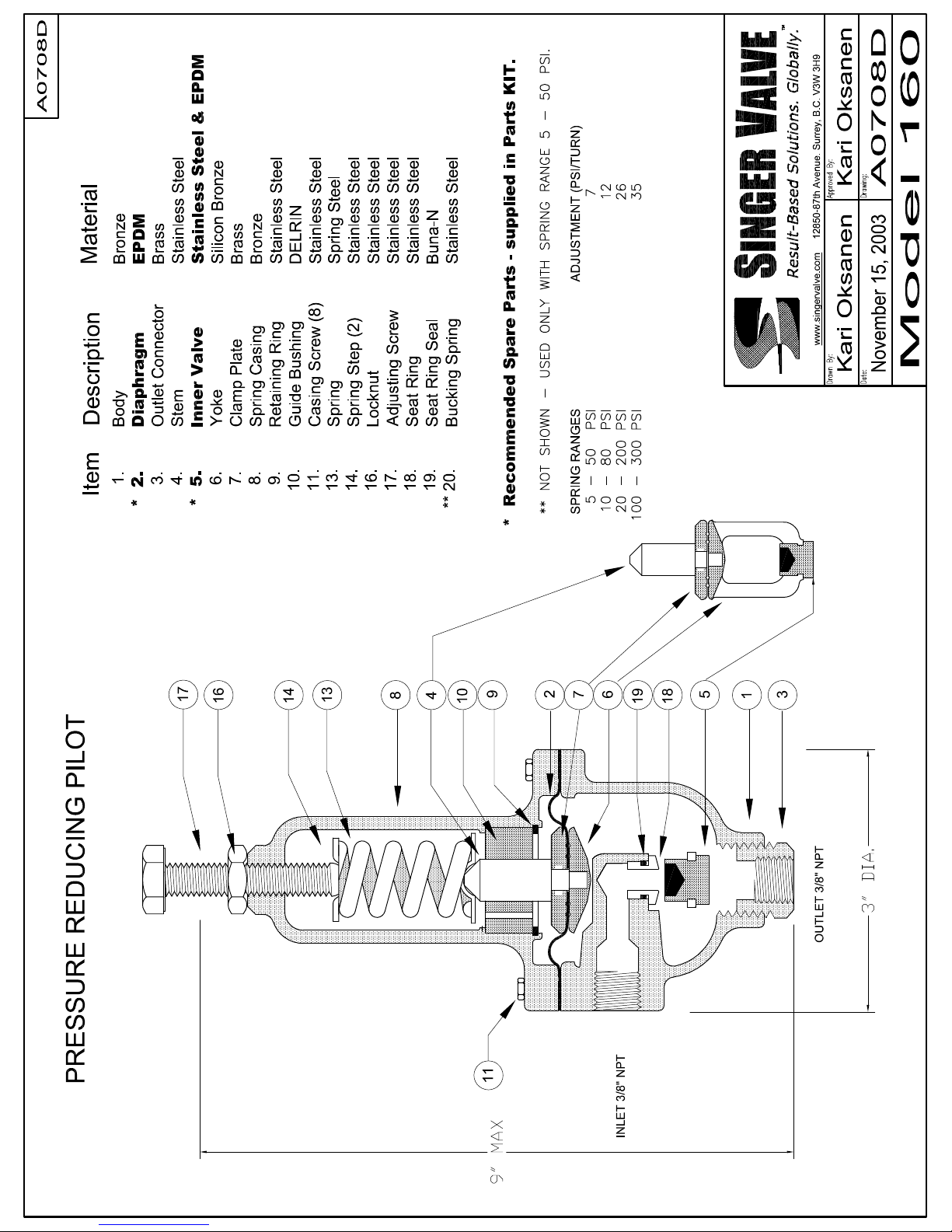
Pressure Reducing Pilot Drawing A0708D
Installation, Operating and Maintenance Instructions
DESCRIPTION AND OPERATION:
Model 160 is a direct acting, spring and diaphragm type
pressure reducing valve. The valve is held open by the
spring. The outlet pressure acting on the diaphragm
opposes the spring to close the valve.
INSTALLATION:
1. Install the valve as shown in the enclosed schematic
or drawing.
2. Note the direction of flow and install the valve
accordingly.
3. The valve should be installed with the adjusting screw
pointing up.
ADJUSTMENT:
Turn the adjusting screw clockwise for increased
pressure, counterclockwise for reduced pressure setting.
Range of adjustment is shown on the name plate.
DISMANTLING:
1. Close upstream and downstream isolating valves.
2. Remove the valve from the pilot system.
3. Remove the adjusting screw.
4. Remove the body screws (11) and remove the spring
casing assembly.
5. Loosen the diaphragm if it adheres to the body and
remove the Stem/Yoke assembly. Be careful to avoid
damage to the stem as any interference or friction
between the stem (4) and guide bushing (10) can
cause problems.
If further disassembly is required:
INNER VALVE REPLACEMENT:
Hold the inner valve (5) HEX in a vise and use a
screwdriver or similar tool to turn the Yoke (6).
IOM A0708D Page 1 of 1 November 2003
Surrey, BC. Canada. V3W 3H9
12850-87th Avenue
Ph: 604-594-5404
Fx: 604-594-8845
www.singervalve.com
DIAPHRAGM REPLACEMENT:
• Note the orientation of the diaphragm to help install
the replacement diaphragm properly.
• Hold the inner valve (5) HEX in a vise and use a
3/16” Allen Key (Hex Drive) on top of the stem (4) to
turn the stem counterclockwise. If required, use a
screwdriver or similar tool at the Yoke (6) to prevent
the yoke from turning. BE CAREFUL NOT TO
DAMAGE THE STEM GUIDING SURFACE.
• Replace the diaphragm and orient it to straddle the
legs of the yoke.
REASSEMBLY:
Reassembly is the reverse of disassembly. Ensure that
parts are replaced in the sequence shown on the
drawing.
TEST PROCEDURE:
Connect a source of air or water to the inlet. Attach a
3/8" line with a pressure gauge and shut-off valve to the
outlet. Back off the adjusting screw, then proceed to turn
it in. The gauge should show an increase within the
range marked on the valve. Open the shut-off valve
slightly and bleed flow to atmosphere. Pressure should
drop slightly and return to setting when the shut-off valve
is closed. This check should be performed at various
settings.
SERVICE SUGGESTION:
POSSIBLE CAUSE / REMEDY
FAILS TO OPEN:
Valve underset./ Increase setting.
FAILS TO CLOSE:
Valve overset. / Reduce setting.
Obstruction on seat. / Clear obstruction.
Ruptured diaphragm. / Replace diaphragm.
Worn inner valve. / Replace inner valve.
Page 2
 Loading...