

Singer Valve 206-RPS, 106-RPS Installation, Operating And Maintenance Instructions

SINGER MODEL 106/206-RPS
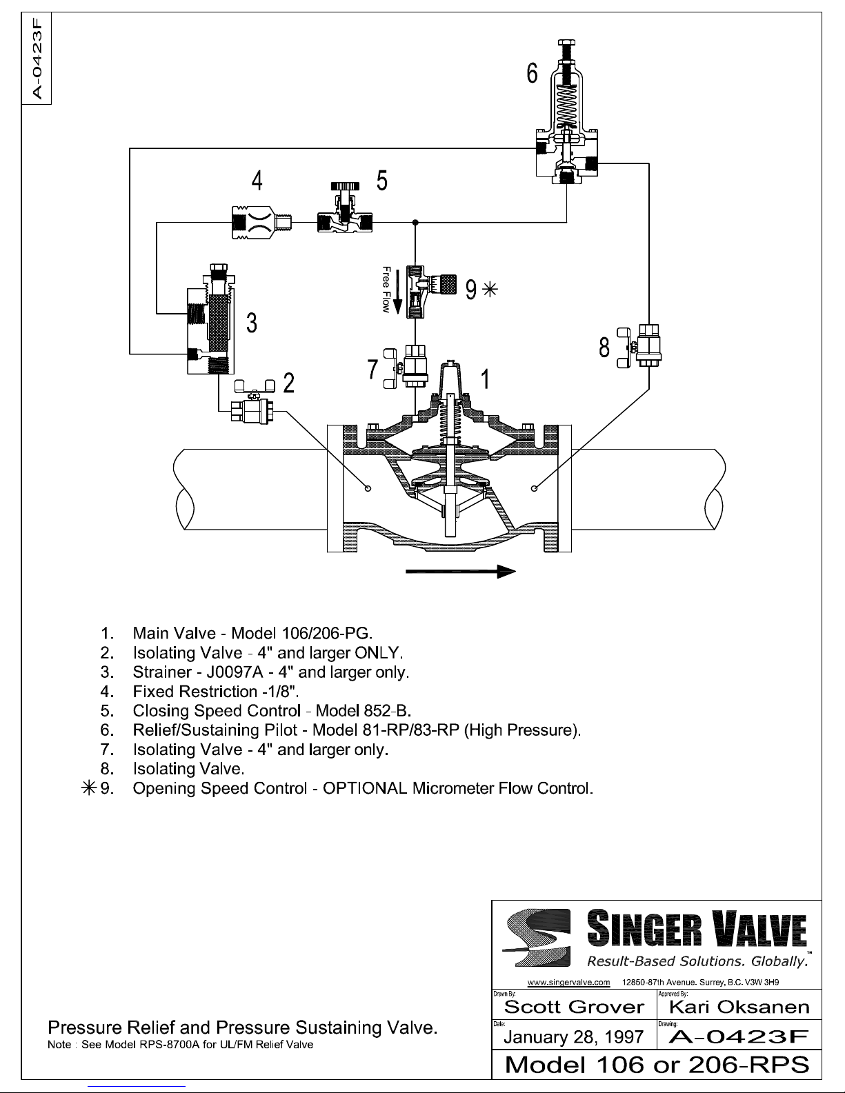
Pressure Relief or Sustaining Valve
Schematic A0423F
DESCRIPTION:
Singer model 106/206-RPS is a pilot operated pressure relief
or pressure sustaining valve designed to open when the inlet
pressure exceeds a predetermined setting.
DESCRIPTION OF OPERATION:
Main Valve (1) is normally open when pressure is applied to
the valve inlet. When the same pressure is applied to the
bonnet, the valve closes tight because the area of the
diaphragm is greater than the area of the seat. By controlling
the bonnet pressure, the Main Valve can be made to open,
close or throttle.
Unless otherwise stated, this valve is built for maximum
temperature of 60o C (140o F).
Bonnet pressure of the Main Valve is controlled with a pilot
circuit consisting primarily of Closing Speed Control (5) and
Relief Pilot (6). Pilot (6) senses the upstream pressure of the
Main Valve. When this pressure is less than the setting of
Pilot (6), Pilot (6) is closed. Pressure from the upstream side
of Main Valve (1) is directed to the bonnet through Closing
Speed Control (5), keeping the Main Valve closed. When the
upstream pressure is greater than the setting of Pilot (6), Pilot
(6) opens to allow flow. If this flow is greater than the flow
coming through Closing Speed Control (5), Main Valve bonnet
pressure is reduced and the Main Valve opens.
When the high pressure has been released and the inlet
pressure drops to less than the setting of Pilot (6), Pilot (6)
closes. This increases the bonnet pressure; the Main Valve
closes. The closing speed is controlled by the setting of
Closing Speed Control (5).
On back pressure service, where the valve is to maintain a
predetermined upstream pressure, Pilot (6) will modulate its
flow so that the bonnet pressure is varied. This, in turn, will
modulate the Main Valve. If the inlet pressure rises slightly,
Pilot (6) opens a little wider and causes the Main Valve to
open further. When the inlet pressure decreases, Pilot (6)
closes slightly and the Main Valve will also close slightly. The
valve reacts to maintain the upstream pressure with varying
flows.
OPTIONAL Opening Speed Control (9) controls flow out of
the bonnet of the Main Valve, thereby controlling the opening
speed. Controlling opening speed can help stabilize the valve
at low flows.
Installation, Operating and Maintenance Instructions
IOM A0423F Page 1 of 1 March 2006
Surrey, BC. Canada. V3W 3H9
12850-87th Avenue
Ph: 604-594-5404
Fx: 604-594-8845
www.singervalve.com
INSTALLATION:
1. See 106/206-PG “Installation”.
2. Improved accuracy of control can be achieved by
connecting the sensing of pilot (6) to header or upstream
of the valve.
3. After pressurizing the valve, bleed air from the bonnet.
ADJUSTING PROCEDURE:
1. Turn adjusting screw of Relief Pilot (6) counterclockwise
until spring is free.
2. Apply pressure to valve inlet. Main Valve (1) should be
wide open.
3. Turn adjusting screw slowly clockwise until pressure at the
Main Valve inlet reaches desired point.
4. Lock adjusting screw in place. Valve is now set to relieve
at the desired pressure.
TROUBLESHOOTING AND MAINTENANCE:
Unstable operation: Bleed air from the Bonnet. Connect
sensing line to header. Install Opening Speed Control.
Valve does not open: Pilot set too high. Isolating Valve(s)
closed. Opening Speed Control closed. Pilot Diaphragm
ruptured. Not enough pressure drop on the Main Valve.
Valve does not close: Closing Speed Control (5) closed.
Strainer (3) plugged. Obstruction in the line from inlet to
bonnet. Main Valve Diaphragm ruptured. Obstruction in the
Main Valve. Ball Valve (9) connects the bonnet to
atmosphere.
Maintenance: Clean Strainer. Frequency depends on local
conditions. Clean Main Valve and Pilot as required. Lubricate
the Body Seal in the Pilot. No other lubrication is required.
Check condition of Main Valve and Pilot Diaphragms and
other resilient parts. Replace when required.
To increase pressure setting of pilot valve, turn adjusting
screw clockwise. As an approximate guide:
Range 1 turn equals
5 - 50 psi 8 psi change
10 - 80 psi 10 psi change
20 - 200 psi 25 psi change
100 - 300 psi 40 psi change
200 - 500 psi 42 psi change
To close Main Valve faster, turn Closing Speed Control (5)
counterclockwise, to close Main Valve slower, turn Closing
Speed Control (5) clockwise - do not close tight.
 Loading...