

Singer Valve 106-RF, 206-RF Installation, Operating And Maintenance Instructions

SINGER MODEL 106/206-RF
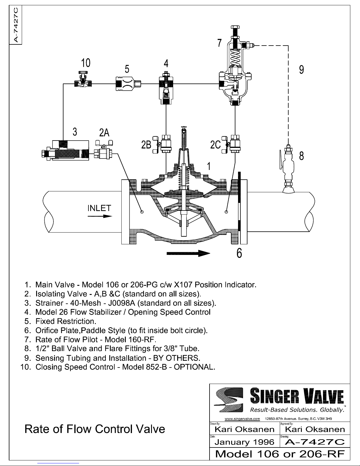
Rate of Flow Control (Flow Limiting) Valve
Schematic A-7427C
Installation, Operating and Maintenance Instructions
DESCRIPTION:
The Singer Model 106/206-RF is a pilot operated
valve that limits the flow to a predetermined
maximum regardless of upstream and downstream
pressure fluctuations. Flow Limiting Pilot (7) senses
differential pressure across Orifice Plate (6) and
positions Main Valve (1) as required to limit the flow
to the predetermined maximum.
The flow setting can be adjusted over a limited range
by adjusting Pilot (7); a typical ratio is 2:1 between
maximum and minimum flow setting. Orifice Plate
(6) must be changed for flow setting outside of this
range.
Differential pressure setting of Pilot (7) is designed to
minimize the pressure drop across Orifice Plate for
the set point flow. Normally, Orifice Plate differential
pressure is 3 at the low end of the range and 12 psi at
the high end of the range. Pressure drop across
Orifice Plate (6) increases exponentially as the flow
setting is increased.
DESCRIPTION OF OPERATION:
Main Valve (1) is normally open when pressure is
applied to the valve inlet. When the same pressure is
applied to the bonnet, the Main Valve closes tight
because the area of the diaphragm is greater than the
area of the seat. Pressure above the diaphragm
determines the position of the Main Valve.
Pressure above the diaphragm is controlled by a pilot
circuit consisting primarily of Fixed Restriction (5) and
Rate of Flow Pilot (7). Pilot (7) senses the pressure
differential produced by Orifice Plate (6).
At flows below set point, Pilot (7) is open because the
differential pressure produced by Orifice Plate (6) is
not sufficient to overcome the spring force of the
Pilot. The bonnet of the Main Valve is vented to
downstream and the Main Valve remains open.
When flow reaches the desired maximum, pressure
drop across Orifice Plate (6) closes Pilot (7). Bonnet
pressure increases and Main Valve (1) starts closing.
The valve then modulates to keep the flow from
exceeding the set point.
IOM A-7427C Page 1 of 1 January 2008
Surrey, BC. Canada. V3W 3H9
www.singervalve.com
INSTALLATION:
1. See 106/206-PG "Installation".
2. Install Orifice Plate (6) between two flanges
downstream of the Main Valve outlet. The Orifice
Plate is designed to fit inside the bolt circle of the
Main Valve.
3.
INSTALL BALL VALVE (8) WITH PILOT TUBE
FITTINGS IN THE CUSTOMER SUPPLIED HEADER
CONNECTION
, as shown on Schematic A-7427C.
4. NOTE: Singer supplied orifice housing, with all
necessary pilot connections, are available as an
OPTION.
5. Pressurize the valve slowly and vent air from the
Main Valve bonnet. Use Wing Nut on top of the
Position Indicator to bleed air.
ADJUSTMENT:
1. To adjust the flow setting, turn Pilot (7) adjusting
screw counterclockwise for reduced flow,
clockwise for increased flow.
2. If the valve starts to oscillate or hunt, adjust Flow
Stabilizer (4). Refer to Model 26 instructions.
SERVICE SUGGESTIONS:
In addition to service suggestions listed in the 106PG/206-PG instruction, we suggest the following:
IF THE VALVE FAILS TO CLOSE:
Check that Isolating Valves (2A), (2B) and (8) are
open. Close Isolating Valve (2C). If the Main Valve
closes, Pilot (7) is defective.
If the valve does not close, close Isolating Valve (2A).
Remove the copper tube between Strainer (3) and
Flow Stabilizer (4). If there is continuous flow from
Flow Stabilizer (4), Main Valve diaphragm is ruptured.
If there is no flow from Flow Stabilizer (4), open
Isolating Valve (2A) slowly. If there is no flow, Strainer
(3) is plugged.
IF THE VALVE FAILS TO OPEN:
• Isolating Valve (2B) or (2C) is closed.
• Flow Stabilizer (4), if so equipped, is incorrectly
set.
• Insufficient pressure drop available.
12850-87th Avenue
Ph: 604-594-5404
Fx: 604-594-8845
 Loading...