

Singer 591D303A, 591D305A Service Manual
SERVICE
INSTRUCTIONS
(PULLER
FEED
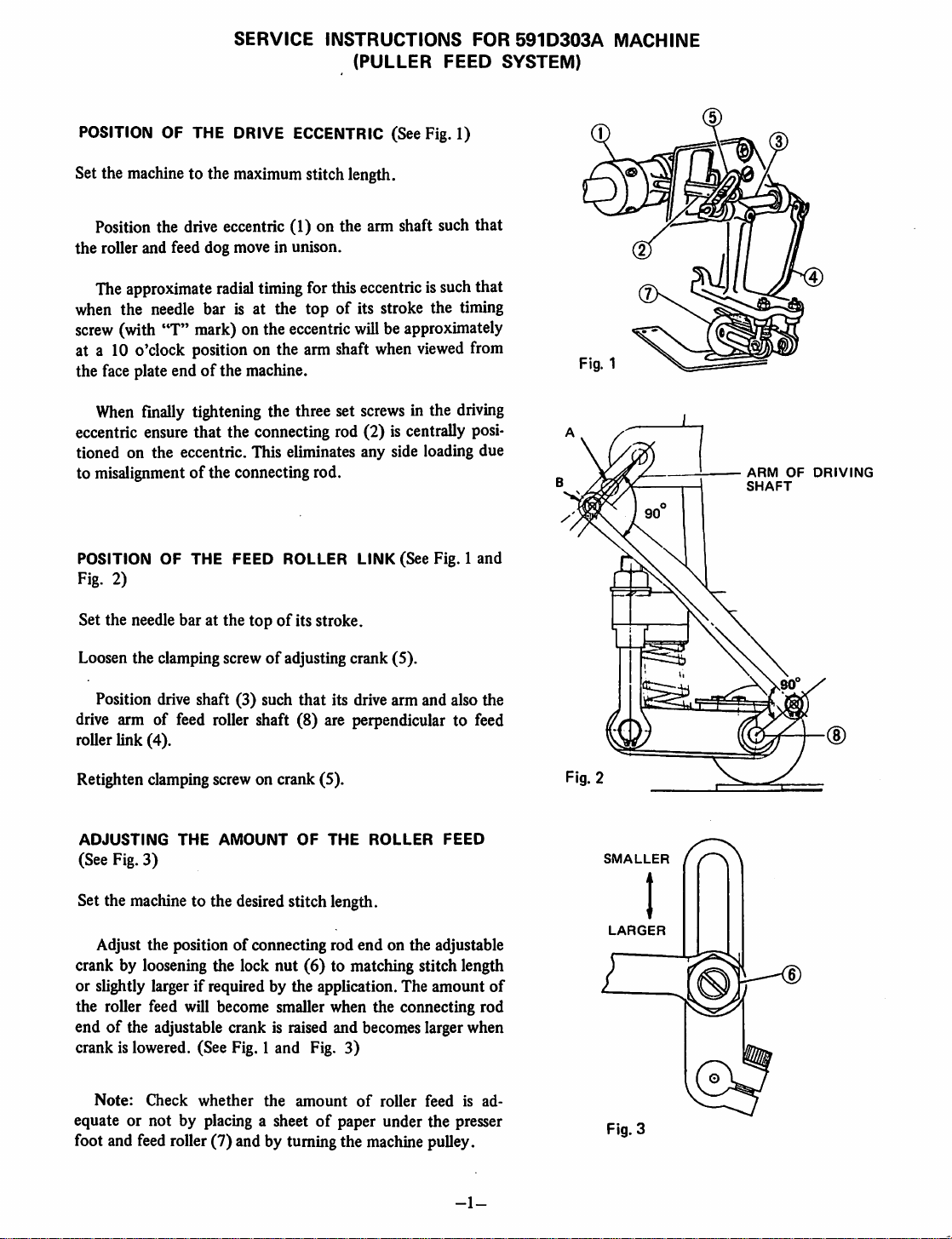
POSITION OF THE DRIVE ECCENTRIC (See Fig. 1)
Set the machine to the maximumstitch length.
Position the drive eccentric (1) on the arm shaft such that
the
roller and feed dog move in unison.
FOR
SYSTEM)
591D303A
MACHINE
Cm
Theapproximate
radial
timingfor this eccentric is suchthat
when the needle bar is at the topofits stroke the timing
screw
(with "T" mark)on the
at a 10 o'clock positionon the arm shaft when
eccentric
willbeapproximately
viewed
from
the face plate endofthe machine.
When
finally tightening the three set
screws
in the driving
eccentric ensure that the connecting rod (2) is centrally posi
tioned on the eccentric. This eliminates any side loading due
to misalignmentofthe connecting rod.
POSITION OF THE FEED ROLLER LINK (See Fig. 1 and
Fig. 2)
Set the needle bar at the
Loosen the clamping screw
topofits stroke.
of
adjusting crank (5).
Position drive shaft (3) such that its drive arm and also the
drive arm of feed roller shaft (8) are perpendicular to feed
roller link (4).
Retighten clamping screw on crank (5).
ARM
SHAFT
OF
DRIVING
ADJUSTING
(See Fig. 3)
THE
AMOUNT
OF
THE
ROLLER
FEED
SMALLER
Set the machine to the desired stitch length.
Adjust the positionofconnecting rod
crank by loosening the lock
nut
(6)
end
on the adjustable
to matching stitch length
or slightly larger if required by the application. The amount
of
LARGER
the roller feed will become smaller when the connecting rod
endofthe adjustable crank is raised and becomes larger when
crank is lowered. (See Fig. 1 and Fig. 3)
Note:
CHieck
equate or not by placing a sheetofpaper under the presser
foot and feed roller (7) and by turning the machine puUey.
whether
the
amount
of
roller
feedisad
Fig. 3
-1-

HOW
TO USE THE
TWO
HOLES ON THE LEVER OF THE DRIVING SHAFT (See Fig. 2)
The 2 holes
provided
on the
driving
shaft(3) leverisusedas
sewing machine which is set with the feed regulating dial.
When the sewing machine stitch length is set within the boundaries
use the short pitch hole A.
When the sewing machine stitch length is set between 10 SJ*.I and 4
use the long pitch hole B.
OILING (See Fig. 4)
In addition to the automatic oil wicking system, it is re
commended
a few dropsofSINGER TYPE
"C"
oil be
that
added every two weeks to the location shown in Fig. 4.
If the needle bearings of drive shaft (3) are replaced, they
should be packed with a bearing grease similar to Exxon
Unirex
N3.
follows
depending
of20SJ
SJ.I.,
OIL
THESE
POINTS
TWO
WEEKS
SINGER
"C"
OIL
uponthe stitch lengthof the
.1.—8
SP.I.,
NEEDLE
BEARINGS
EVERY
TYPE
TO
REPLACE
THE
REAR
COVER
Whenrear cover plate is replaced after
pound (Three
oil leakage.
TO
REPLACE
Bond
#1104 or equivalent) to the
THE
FEED
ROLLER
(See Fig. 5)
Hook the ballofthe lifting cable
(10) adjusting the ball
place. Fix with the lock
upward
nut
(11).
sothat it willnot vibrate out of
PLATE
removing
LIFTING
(9)
into the lifting arm
it from the rearofarm, it is necessary to apply seal com
CABLE
gasket
Fig. 4
glued
onto the cover plate in order to prevent
(0)
Fig. 5
-2-
 Loading...