

Singer 510K Service Manual
SINGER
Service
CLASS
Manual
510K
THE
SINGER
COMPANY
SINGER
Gfu/ipfne^
USE
SINGER
OILS
and
They insure freedom
The
following
TYPE
stain on fabrics, even after a long period of storage, use:
TYPE
A — MANUFACTURING MACHINE
When an oil is desired which will produce a minimum
C — MANUFACTURING MACHINE
are the correct lubricants for these
OTHER
LUBRICANTS
longer
SINGER*
from
life
lubricating trouble and give
to
sewing
equipment
OIL,
LIGHT GRADE
OIL,
LIGHT GRADE
LUBRICANTS
machines:
of
TYPE
type
GEAR
E -THREAD
For lubricating the needle thread of sewing machines for stitching
fabrics or leather where a thread lubricant is required.
F-motor
For
oil-lubricated
transmitters.
NOTE:
tins
LUBRICANT
All oils
and5gallon
This
specially prepared grease is recommended for
lubrication on manufacturing sewing machines.
LUBRICANT
oil
motors
are
and
available
drums.
plain
bearingsinpower
in 1
quart
and
tables and
1 gallon
gear

Form
(768)
K6783
SINGER
Service
Class
51
OK
SINGER
Manual
Machines
*A
Trademark
of
The
Copyright
Copyright
Alt
Singer
Rights
© 1968^ by
Under
Company
Machine
International
Reserved
510K111
THE
SINGER
Copyright
Throughout
COMPANY
Union
The JfJorld
Printed
in
Great
Britain

GENERAL
INDEX
Page
Description of
Installation
General
information
Machines
and
Operation
Installation
Lubrication
Machine
pulley ^
Needle ^
Speed
Stitch
Thread
Setting
Adjusting feed
Adjusting
Feed
Needle
length ^
tension
and
Timing
feed
dog
height, level
bar
height
driving
eccentric
eccentric
cam
and
centralisation
gib
16
^
®
^
^
^
Q
^
Needle
Presser
bar bushing height 1^
bar
Specifications
Stitch
length
Timing arm
Timing
Timing
Timing
Removal
Arm
Arm
Face
Feed
Looper
Looper
Looper
Needle
Presser
feed
looper
"machine
and
shaft
shaft
plate
driving
driving
shaft
bar
bar
height
shaft
Replacement
connection
and
shaft
and
and
looper
belt
feed
looper
lifting
shaft
driving
rock
bushing
shaft
shafts
12
17
12
17
12
24
22
26
21
20
21
23
23
-2
-
DESCRIPTION
Class
510K
chainstitch
GENERAL
Long
Bed
dimensions:
(457,2
mm),
needle,
Drop
with
pin.
Rotating
Socket-type
One
needle.
Single
Semi-automatic
FEATURES
arm,
mm).
Working space
11
Feed,
adjustable
looper.
thread
Machines
machines
flat
bed.
Length,
Width, 7
inches
Pendant
feed
needle
chain
lubrication.
are
high
speed,
for basting light to
at
(279,4
link
levelling
bar.
stitch,
18-3/4
inches
right
mm).
feed
(177,8
of
mechanism
eccentric
F.S.T,
inches,
101,
one
needle,
heavy
rotating
weight
SPECIAL CHARACTERISTICS OF
MACHINE
Lighttomedium
Needle
Needle
Presser
Stitch
Speed
looper,
men's
510K110
bar
bar
length
and
women's
VARIETIES
weight
stroke:
lift
drop
feed
:
Cat,1901
1
:
5/16
:
Max,4per
Min,12
:
Max,
fabrics.
sizes
inch
mm)
mm) ,
single
clothing.
MACHINE
(chromium),
12
to
(25,4
inch
5,000
per
(7,9
inch
inch
s.p.m.
thread
25,
mm),
mm).
(25,4
(25,4
Double
ends
of
looper
Needle
feed
lifting
connecting
Knee
Tapped
lifter.
hole
provided
Machine
V-belt,
groove,
Effective
mm)
round
(60,3
Totally
an
Single
at
order.
extra
no
mm),
spool
extra
shielded
arm
shaft
driving
bearings
link
and
for
mounting a
pulley
Outside
2,9
inches
diameter
leather
enclosed
charge.
thread
charge
ball
bearings
and
at
shaft.
for
feed
connections,
and
looper
seat
for
in
3/8
diameter
(73,66
for
belt,
Belt
Guard
unwinder
if
specified
pulley
driving
rear
light
inch
5/16
2-3/8
needle
shaft.
of
(9,5
of
mm).
inch
available
available
at
both
end
and
bar
arm
fixture.
mm)
belt
(7,9
inches
on
of
at
MACHINE
Medium
Needle
Needle
Presser
Stitch
510K111
to
heavy
bar
stroke:
bar
length
lift
weight
:
Cat,3355
sizes
1,7/16
:
3/8
: Max,2^
mm)
Min,12
mm)
Speed : Max,
stitch
12,
Max,
stitch
4.
NOTE:
For
long,
maximum
500
s.p.m.
continuous runs reduce
machine speeds by approximately
fabrics.
12
inches
inch
per
per
5,000
lengths
4,000
lengths
(chromium),
to
25,
(36,5
(9,5
mm)
inch
inch
s.p.m,
s.p.m,
(25,4
(25,4
for
4
for
2^
mm)
to
to
- 3 -

SETTING
UP
DRIP
Position
as
shown
even
with
cut-out
Using
fasten
out
to
rod
(shown
KNEE
Using
(shown
bracket
bracket
and
fall
drip
pan
Locate
rock
lever
and
rear
Make
of
certain
rod
lifting
tighten
PAN
in
four
drip
avoid
LIFTER
three
at
2
2
rock,
will
rod
clamp
drip
in
Fig.
right
table.
3/4
pan
interference
in
7/8
1,
Fig.
to
underside
so
that
through
without
lever
rod
edges
that
be
in
pan
on
2,
with
inside
inch
low
enough
Fig.
screw
2).
inch
2)
rock
hole
striking
extension
equidistant
of
hole
platform
directly
machine;
underside
its
edge
(19
mm)
with
(22
mm)
fasten
of
table.
lever
provided
edge
in
drip
under
then
4.
right
of
wire
in
wood
rock
rod
3
from
at
of
table,
machine
nails,
table
rock
screws
lever
Locate
can
for
of
hole.
to
hold
front
pan.
top
end
knee
securely
end
cut
lever
it
rise
in
PLATFORM
Fig.
ROCK
2.
FRONT
EDGEOFTABLE
^ 7
;
LEVER
ROD-
Drip
Pan
beneath
the
and
Knee
Table.
% S
Lifter
Raise
platform
machine,
platform
and
securely
Knee
plate
turned
operator,
8.
Knee
toward
or
rear
Tighten
correct
Set
stop
knee
lifter
presser
lifter
clamping
rock
to
the
after
both
position
foot
on
lever
just
when
is
turned
tighten
7 may
suit
after
plate
left
screws
stud
as
high
machine.
screw
rod
below
at
rest.
as
be
the
requirements
loosening
arm
or
right
loosening
is
11
to
soon
enough
12.
5
to
knee
lifting
Make
shown
clamping
raised,
9 may
and
clamping
8
and
obtained.
stop
as
ttie
knee
to
Securely
bring
certain
in
Fig.
screw
lowered
clamping
also
be
toward
10
securely
action
lifter
trip
tighten
its
rod
of
moved
screw
hand
in
2
6.
or
the
screw
front
when
of
raises
10.
the
MACHINE
Machine
pads
in
Machine
support
back
upon
MACHINE
When
machine
pulley
the
operator.
CAUTION:
NOT
EVEN
IT
HAS
HEAD
head
hinges
head
must
should
four
comers
must
except
machine
PULLEY
is
always
DO
NOT START THE MACHINE,
TO TEST THE SPEED, UNTIL
BEEN
THOROUGHLY
rest
in
operation,
turn
rest
of
not
when
upon
cut-out
be
machine
pin
over
used
on
TOWARD
OILED.
cushioning
in
table.
to
is
tilted
table.
machine
Fig,
3.
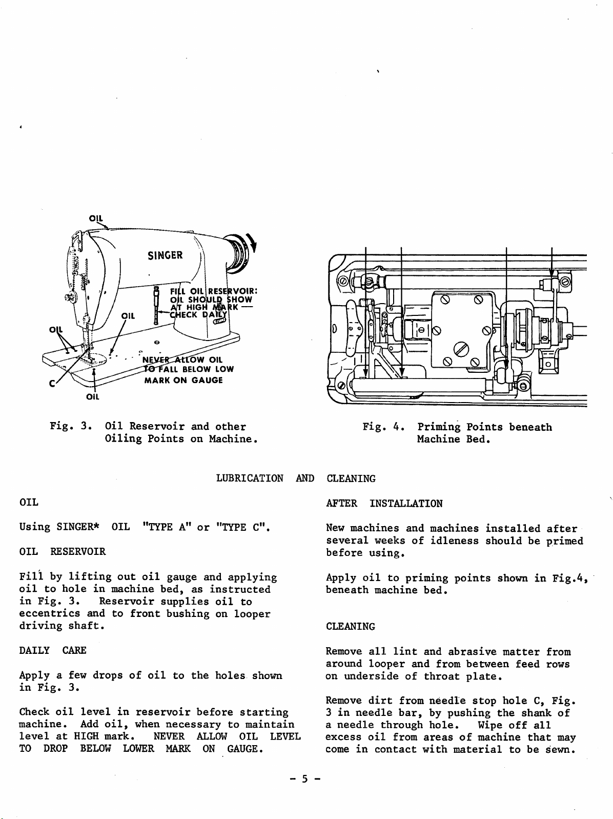
OIL
OIL
Oil
Oiling
SINGER
'ALL
MARK
Reservoir
Points
FILL
ON
OIL
[OW
BELOW
GAUGE
and
on
reservoir:
»HOW
OIL
LOW
other
Machine
Fig.
4.
(S) (S)
Priming
Machine
Points
Bed.
]\
beneath
OIL
Using
OIL
Fill
oil
in
SINGER*
RESERVOIR
by
to
Fig.
eccentrics
driving
DAILY
Apply
in
Check
a
Fig.
oil
machine.
level
TO
at
DROP
lifting
hole
3.
shaft.
CARE
few
3.
HIGH
in
Reservoir
and
drops
level
Add
BELOW
OIL "TYPE A"
out
oil
gauge
machine
bed,
supplies
to
oil,
mark.
front
of
in
when
LOWER
reservoir
bushing
oil
necessary
NEVER
MARK ON
to
or
and
as
instructed
the
before
ALLOW
LUBRICATION
"TYPE
C".
applying
oil
to
on
looper
holes
shown
starting
to
maintain
OIL
GAUGE.
LEVEL
AND
CLEANING
AFTER
New
machines
several
before
Apply
beneath
CLEANING
Remove
around
on
underside
Remove
3
in
needle
a
needle
excess
come
in
INSTALLATION
and
weeks
of
using.
oil
to
priming
machine
all
lint
looper
and
of
dirt
from
bar,
through
oil
from
contact
machines
idleness
bed.
and
from
throat
needle
by
hole.
areas
with
points
abrasive
between
plate.
stop
pushing
of
material
installed
should
shown
matter
hole
the
Wipe
off
machine
to
be
feed
shank
that
be
after
primed
in
from
rows
C,
all
sewn.
Fig.4,
Fig.
of
may
- 5 -
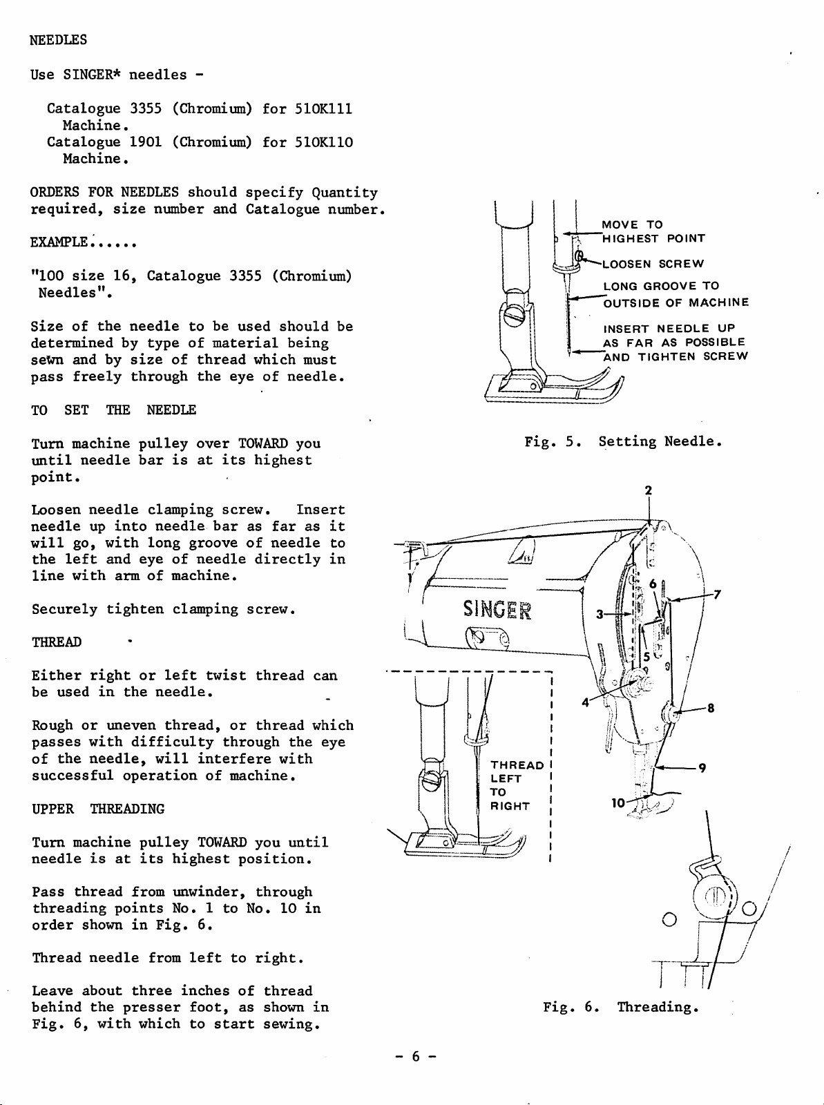
NEEDLES
Use
SINGER*
needles
-
Catalogue
Machine.
Catalogue
Machine•
ORDERS
FOR
required,
EXAMPLE,
"100
Size
size
Needles".
of
determined
seWn
pass
TO
Turn
until
and
freely
SET
machine
needle
point.
3355 (Chromium)
1901
(Chromium)
NEEDLES
size
number
16,
Catalogue
the
needle
by
type
by
size
of
through
THE
NEEDLE
pulley
bar
is
should
and
to
be
of
material
thread
the
over
at
for
510K111
for
510K110
specify
Quantity
Catalogue
3355 (Chromium)
used
should
being
which
eye
TOWARD
its
highest
of
must
needle.
you
number.
be
Fig.
MOVE
t)
5.
HIGHEST
LOOSEN
LONG
OUTSIDE
INSERT
AS
AND
Setting
TO
GROOVE
FAR
TIGHTEN
POINT
SCREW
OF
MACHINE
NEEDLE
AS
POSSIBLE
Needle.
TO
UP
SCREW
Loosen
needle
will
the
line
go,
left
with
Securely
THREAD
Either
be
used
Rough
or
passes
of
the
successful
UPPER
Turn
machine
needle
Pass
thread
threading
order
shown
needle
up
into
with
and
eye
arm
tighten
right
or
in
the
uneven
with
difficulty
needle,
operation
THREADING
pulley
is
at
its
from
points
in
clamping
needle
long
groove
of
of
machine.
clamping
left
needle.
thread,
will
highest
unwinder,
No.
Fig.
screw.
bar
needle
twist
or
through
interfere
of
machine.
TOWARD
position.
1
to
6.
as
far
of
needle
directly
screw.
thread
thread
you
through
No.
the
with
until
10
Insert
as
can
which
eye
in
it
in
to
THREAD
LEFT
TO
RIGHT
5l
\ fe
Thread
Leave
behind
Fig.
needle
about
the
6,
with
from
three
presser
which
left
inches
foot,
to
to
start
of
as
right.
thread
shown
sewing.
in
Fig.
- 6 -
6.
Threading.
TURN
ADJUST
MORE
PRESSURE
LESS
PRESSURE
TO
Pressure
as
possible,
correct
To
increase
downward
turn
Do
screw
not
presser
on
the
displaced.
Pressure
steadily
TO
REGULATE
on
material
while
feeding.
pressure
(clockwise)•
upward
completely
foot
otherwise
top
of
is
correct
and
smoothly
THE
should
sufficient
turn
(anti-clockwise).
release
the
presser
when
LENGTH
this
To
reduce
pressure
the
bar
work
without
be
ball
OF
as
light
to
insure
screw
pressure
on
bearing
may
be
moves
stalling.
STITCH
Fig.
Fig.
7.
8.
Regulating
Pressure.
Regulating
SINGER
PLUNGER
Stitch
Presser
Foot
Length.
To
change
STOP
Depress
instructed
Turn
slowly
Then
indicating
opposite
release
Never
running.
Make
certain
before
TO
START
machine
machine
until
turn
depress
starting
the
length
plunger
in
machine
desired
mark
plunger.
plunger
that
SEWING
of
in
Fig.
pulley
plunger
pulley,
P,
Fig.
plunger
machine.
stitch....
machine
8
and
over
drops
stitch
8,
while
is
bed
as
TOWARD
(clicks).
until
length
on
arm,
machine
disengaged
you
number
is
and
is
TO
REGULATE
FOOT
Correct
work
pressure
as
shown
ON
MATERIAL
presser
efficiently.
by
means
in
Fig.
PRESSURE
foot
of
7.
pressure
You
screw
OF
can
PRESSER
helps
regulate
on
top
of
feed
arm,
Place
presser
to
TOWARD
out
does
line
should
this
- 7 -
the
sew,
by
not
of
position.
material
foot,
turning
you.
the
stand
motion
be
turned
lower
If
needle
out
of
and
presser
the
machine
the
for
at
the
slightly
thread
thread
the
right
looper,
foot
pulley
loop
looper
angles
to
bring
beneath
and
thrown
to
the
start
over*
catch
to
needle
it
the
the
into
 Loading...