

Page 1

SINGER
504W1
Page 2
MACHINE
____.—-———
N0.
504w1
THE
SINGER
MANUFACTURING
COMPANY
A
"
i
7
I
t
,
Page 3
LIST
or
PARTS
COMPLETE
the
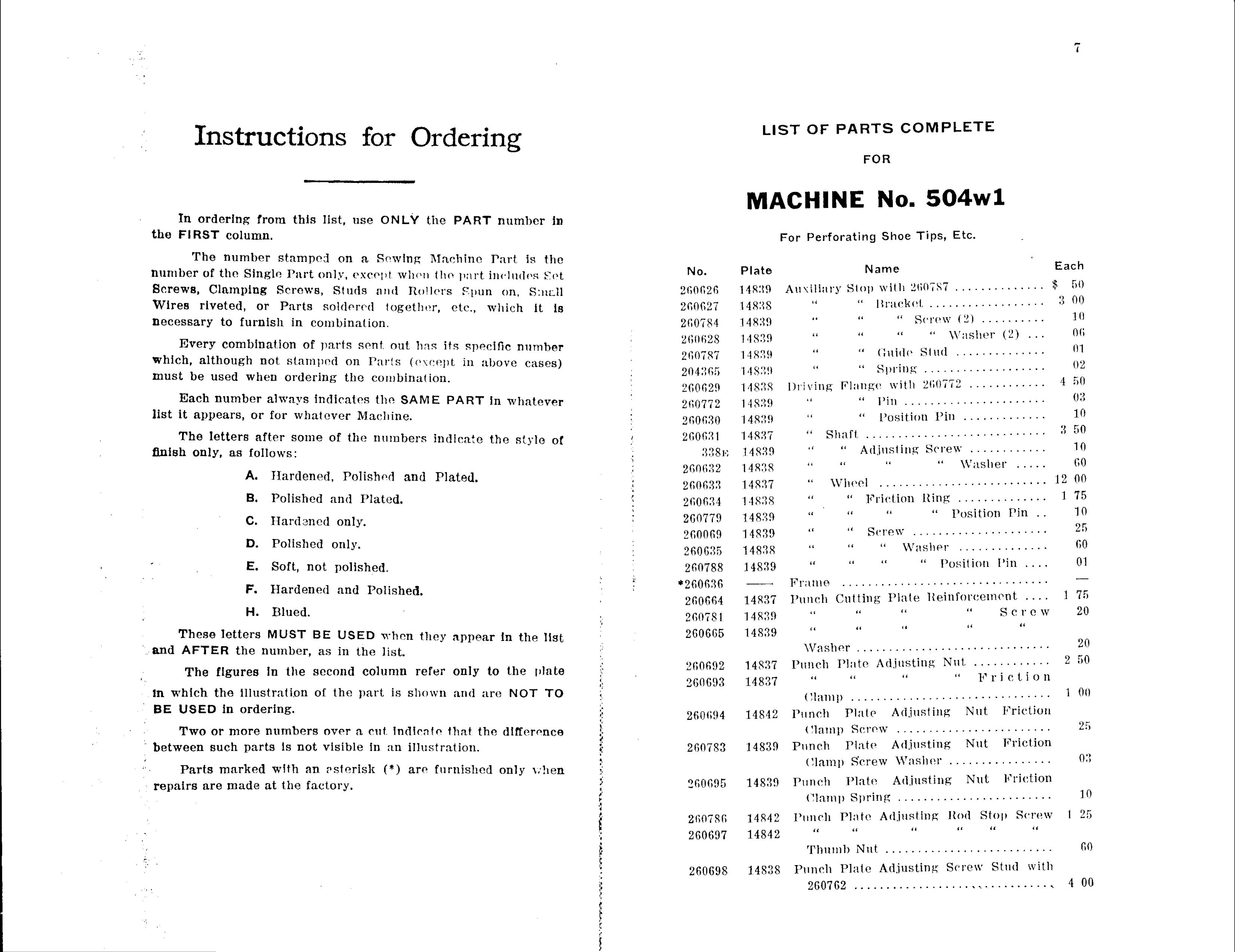
Instructions
In
FIRST
ordering
from
column.
this
list,
for
use
Ordering
ONLY
the
PART
number
in
MACHINE
For
Perforating
FOR
N0.
Shoe
504w1
Tips,
Etc.
The
number
of
Screws,
Wires
necessary
Every
which,
must
riveted,
although
be
number
the
Single
Clamping
or
to
combination
used
furnish
not
when
stamped
Part
only,
Screws,
Parts
in
stamped
ordering
combination.
of
parts
on
a
except
Studs
soldered
sent
on
the
Parts
Sewing
when
and
Rollers
Machine
the
together,
out
combination.
has
(except
its
part
Spun
etc,
specific
in
Part,
includes
on,
which
number
above
is
Small
cases)
it
the
Set.
is
No.
260626
260627
260784
260628
260787
204365
260629
Plate
14839
14838
14839
14830
14839
14830
14833
Atwiliary
“
"
“
“
“
Driving
Name
Stop
“
“
“
“
“
Flange
with
Bracket
“
260767
Screw
“
(iuidc
Sprhlg
with
..............
...................
(2]
“
Stud
...................
260772
Washer
..............
............
..........
(2)
...
Each
$
3
50
00
10
06
4
01
02
50
Each
list
finish
it
The
number
appears,
letters
only,
as
always
or
after
follows:
A.
.
B
for
Hardened,
Polished
indicates
whatever
some
of
and
the
Machine.
the
numbers
Polished
Plated.
SAME
and
PART
indicate
Plated.
in
the
Whatever
style
of
L
I
260772
260630
260631
338m
260632
260633
260634
14839
14839
14837
14330
14338
14337
148?“
“
“
“
“
“
“
“
Shaft,
“
“
Wheel
“
“
“
l’in
Position
......................
Pin
.............
............................
Adjusting
“
Screw
“
............
Washer
.....
..........................
Friction
Ring:
..............
3
12
1
03
10
50
10
60
00
75
C
D.
E.
F.
H.
Hardened
Polished
Soft,
Hardened
Blued.
not
only.
only.
polished.
and
Polished.
‘
f
260779
260069
260635
260788
*260636
260664
260781
14839
14839
14838
14839
——~
14837
14330
“
“
'
“
“
Frame
Punch
“
“
“
“
“
................................
Cutting
“
Screw
“
“
“
Plate
.....................
Washer
“
“
“
Reinforcement
Position
..............
Position
“
I’iu
Pin
S
C
....
r
c
..
w
l
10
25
60
01
—
75
20
’
2
‘
and
in
BE
These
AFTER
The
which
USED
Two
letters
the
figures
the
in
or
more
illustration
ordering.
MUST
number,
in
numbers
the
BE
as
second
of
over
USED
in
the
when
the
column
part
a
cut,
list.
they
refer
is
indicate
shown
appear
only
and
that
the
to
are
in
the
difference
the
NOT
list
plate
TO
260665
260602
260693
260694
14839
14337
14837
14842
“
\Vaslier
Punch
“
(llamp
Punch
(llamp
“
..............................
Plate
“
...............................
Plate
Screw
“
Adjusting
“
Adjusting
........................
Nut,
“
“
............
C
i
F
Nut
r
Friction
“
ti
on
2
1
20
50
00
25
‘
between
Parts
repairs
such
are
parts
marked
made
with
at;
is
the
not
an
factory.
visible
asterisk
in
an
(*)
illustration.
are
furnished
only
when
5.3a”!—
2,2.
\._
£.Y\_.
cc“)
260783
260695
260786
260697
14839
14830
14342
14842
Punch
(llamp
Punch
Clamp
Punch
“
Thumb
Plate
S'crew
Plate
Spring
Plate
“
Nut
Adjusting
Washer
Adjusting
........................
Adjusting
................
Rod
“
..........................
Nut
"
Nut
Stop
“
Friction
Friction
Screw
“
l
03
10
25
60
on“.
.w
mar;
raw-Tn
\%
260698
14838
Punch
260762
Plate
...................
Adjustingr
Screw
Stud
..........
t
with
t
4
00
Page 4
,
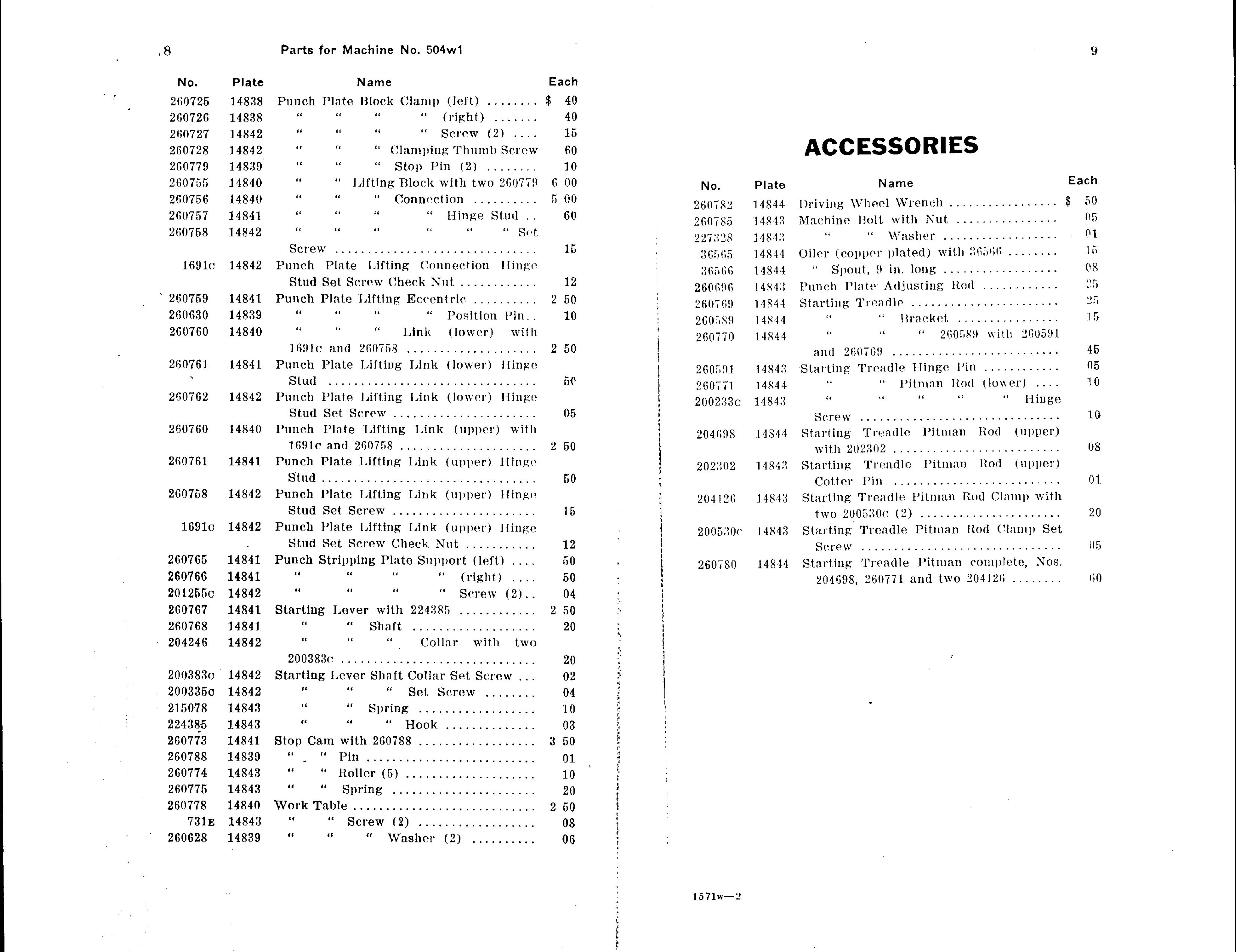
8
Parts
for
Machine
No.
504w1
9
No.
260725
260726
260727
260728
260779
260755
Plate
14838
14838
14842
14842
14838
14840
Punch
“
“
“
“
“
Plate
”
“
“
“
“
Name
Block
“
“
“
“
Lifting
Clamping
Clamp
“
“
Stop
Block
(rigllt)
Screw
Pin
with
(left)
Thumb
(2)
two
........
.......
(2)
Screw
........
260779
Each
$
40
40
15
60
10
6
00
No.
Plate
ACCESSORIES
Name
Each
260756
260757
260758
16910
‘
260759
14840
14841
14842
14842
14841
“
“
”
Screw
Punch
Stud
Punch
“
“
“
...............................
Plate
Set
Plate
Screw
“
“
Connection
“
Lifting
Check
Liftingr
“
Hinge
“
Connection
Nut
Eccentric
.............
..........
Stud
“
..........
“
Hinge
..
Sct
5
2
00
60
15
12
50
2607(2
260785
227328
36565
36566
260606
260769
14844
14843
14843
14844
14844
14843
14844
Driving
Machine
“
()iler
“
Punch
Starting
(copper
Spout,
Wheel
ilolt
”
9
Plate
’l‘readle
Wrench
with
Washer
plated)
in.
Adjusting
long
.......................
Nut
with
.................
................
..................
36566
........
..................
Rod
............
$
50
05
01
15
08
‘35
25
260630
260760
260761
260762
14839
14840
14841
14842
“
“
16910
Punch
Stud
Punch
Stud
“
“
and
Plate
................................
Plate
Set
260758
Lifting
Lifting
Screw
”
“
“
Link
Position
(lower)
Pin“
with
....................
Link
Link
......................
(lower)
(lower)
Hinge
Hinge
2
10
50
50
05
260589
260770
260591
260771
200233C
14844
14844
14843
14844
14843
“
“
and
Starting
“
260769
“
Screw
“
“
Bracket
“
260580
................
with
260591
..........................
Treadle
“
Pitman
“
...............................
Hinge
“
l’in
Rod
“
............
(lower)
“
Hinge
'15
45
05
10
10
260760
260761
260758
16910
14840
14841
14842
14842
Punch
16910
Punch
Stud
Punch
Stud
Punch
Plate
and
Plate
Lifting
260758
Lifting
Link
(upper)
with
.....................
Link
(upper)
Hinge
.................................
Plate
Set
Plate
Screw
Lifting
......................
Lifting
Link
Link
(upper)
(upper)
liingc,
Hinge
2
50
50
15
204698
202302
204126
2005300
14844
14843
14843
14843
Starting
with
Starting
202302
Cotter
Starting
two
Starting
2005300
Trcadle
..........................
Treadle
Pin
Treadie
Treadle
..........................
(2)
Pitman
Pitman
Pitman
......................
Pitman
Rod
Rod
Rod
Rod
Clamp
(‘iamp
(upper)
(upper)
with
08
01
20
Set
‘
260765
260766
2012550
260767
260768
204246
14841
14841
14842
14841
14841
14842
Stud
Punch
Stripping
”
“
Starting
“
“
Set
Lever
Screw
“
“
with
“
“
Shaft
Check
Plate
“
“
“
_
Nut
Support
“
"
224385
...................
Collar
...........
(left)
.
.
.
night)
Screw
(2)
.
............
with
two
.
.
2
12
50
50
04
50
20
260780
14844
Screw
Starting
204698,
...............................
Treadie
260771
Pitman
and
two
complete,
204126
........
Nos
05
60
2003830
2003350
215078
224385
260773
260788
14842
14842
14843
14843
14841
14839
2003830
Starting
“
“
“
Stop
“
Cam
‘
Lever
with
“
Pin
..............................
“
”
“
Shaft
“
Spring
“
260788
Collar
Set
..................
liook
..................
Set
Screw
Screw
........
..............
.
..
..........................
3
20
02
04
10
03
50
01
g.“
at»,4;
1x81".
““7.“
260774
260775
260778
731E
260628
14843
14843
14840
14843
14839
“
“
Work
“
“
“
Itoller
“
Table
“
”
(5)
Spfing
............................
Screw
“
......................
(2)
Washer
....................
..................
(2)
..........
2
10
20
50
08
06
”15.1.1
My
.94..
,
.w
...
..
~nrr1.
157lW—2
Page 5

l t
NUMERICAL
No.
mm:
72111::
Ilittiv‘
Plate
ilSit‘.‘
1184::
11M:
Driving
\\'nrk
l’unr-h
Stud
Shiit't
'l‘nhlt)
['illit‘
Sm
LIST
Name
Adjusting
Scruw
Lifting:
Srron
(Thwk
OF
St-rtm
....................
(‘nnnw-tiun
Nut.
PARTS
........
ilinnv'
tor
200700
Each
S
in
0?:
l.’
illillt:
£111,703
filth—H10
20031wa
2005;235u‘
HM”:
[Hit
Il‘tl
19811;
iiRi‘l
Punt-h
Stud
(tilvr
”
Stzlrtini:
ilingn
Stzlrtinv;
t1'l)|||lt‘l’
Sprint.
i‘lntv
Silt
'l‘rmnlli‘,
Hr-rvw
lim‘t‘r
hitting:
Si'rtiw
plutl‘il)
‘J
in,
........................
Shut't
Link
('ht-n-h
lung,
I’ilnum
with
l'nr
Si‘t
tllppt‘l')
.\'ut.
5241300
31030.3
itmi
St‘rr'w
tnr
ilingu
:Itniun
.......
........
tlnwvr)
t:
I]
”\
in
01
NUMERICAL
MACHINE
LIST
FOR
No.
OF
504W],
PARTS
1200215
BOUSIHH‘
1U
Btti‘lftvw
202220”:
llNiZ
11815;
lthL.‘
HMZ‘.
‘
1'01‘
Starting:
Svrow,
I'llltt‘il
.
Sturtinu
('nttt'r
‘
201310
'I‘rmnilv
for
Stripping
'l‘rvmih'
i’iu,
"
...........................
l'itninn
304120
l‘lutt‘,
l’itlnun
for
thitittt‘s‘
(‘nllur
ltwl
....................
Support
................
SM
(‘lzunp
Sorvw
lint]
St'rtwk
Sol
i.
tllppl'r)
'1;
0.7
01
01
204130
20120".
‘30
:01in
(:03
HRH
HMB
itKiiit
tht
Starting:
two
Stnrting
200:1.‘(CH'
i-\u,\iii:ir.\‘
Starting
with
ZttlJfiillh',
2033102.
'l‘rmniin
Lover
.
Stop
'I‘rmnlh‘
............................
Spring
for
I‘itnuin
for
Shnt't
200780
i'itnutn
ZtHITHtt
Itml
..............
(‘olhu'
..................
(‘hinip
with
limi
lllmtt‘l't
with
two
................
30
'10
03
0"
L’iTHI'A‘
23t3t¥~7
‘:ZTCIE‘N
300000
2003M!
20030]
260031;
tSii‘,
tRiZ‘,
ilRti’.
18319
HS
it
MHZ:
M311!
Starting
“
Mnt'hinv
Driving
Starting
“
Auxiliary
Lm‘vr
“
Holt
\\'hm-]
'l‘t'vmilt'
\VilSiit‘i'
“
Stnp
Spring
“
St'|'(‘\\'
Hrm-kvt,
Hinge
with
................
Hunky
..................
..................
i’in.
120075
['01‘200707
for
for
.............
200770
200770
..
.‘.V
..,.
10
02‘-
0|
2.7
17»
03
7.0
300017
L’tiltti‘lx‘
200004
‘Jtitltt‘ftl
200mm
2000110
HRiIK
Witt
1R1!!!
l‘<3§\‘
ixrtn
11x31»
Work
Driving
I‘nm-h
“
“
“
l’in
"
“
'l‘nhh‘
li‘lnngv
Svrew
"
I'lnto
..................................
Hrur‘kvt,
“
Washer
with
i’nsitinn
Lifting
St'rt‘w
200772
l’in
Flt-(Nitric
................
Washvr
............
............
..............
Position
i1
It
00
00
0|}
30
1"
10
31;ln'.1t
2t;0t:::j
2000.112
gumzxt
1’61th
HM?
IIRIKR
itxz'fi
itK‘f‘N
HEN
Driving
“
“'1‘th
"
“ "
Shut!
“
“
..........................
Adjusting
Si'row
\VHSIH‘I'
...........................
ii‘rivtinu
St'i'mr
Ring
\\':ishvr
..............
............
,.
3'.
1'2
1
3n
00
M
73
00
Page 6

[L
Numerical
List
of
Parts
Numerical
List
of
Parts
15
No.
‘36111‘.:‘.6
26116111
3611665
26116112
26116516
Plate
118217
1182111
118317
1-1837
14‘1'111111'
P11111411
\\':1.<l11-1'
1’11111-11
.............
(71111111:
.............................
1’11111'
1\1l_111s1111}4
1’11111-
”
11121111'1111-1-1111-11l
31'11‘“
N111
‘
.............
1"111-1111111‘11111111
1
75
‘_’II
1.11
1111
No.
211111
1311111111
211117751
1'11117711
211117311
1.1
Plate
1131‘:
11H”
11\::11
llNIIlJ
111\'11
Name
S111111‘;1111H111'111g
\"(11'1(
111111115:
1111'
1’11111-11
Skirting
'1‘111111-
2111177171
\\'111-1\l
l‘l:111-
’1‘1'1-:11ll1-
...........................
11'1'11-111111
...........................
111111-11"
..................
11111};
$11111
1’111111111
l‘11s1111m
1’111,
1-111111111-11-.
1111'
1‘111,
261175171“
X1152
Each
311'
2
3"
T111
111
1H
26116111
ZfiUUHS
212116116
3611611]
118-12
1
182111
1-1812!
11Nl‘l
St‘l‘l‘W
1’11111'11
8111-1111:
1‘11111'11
1111111111
..............................
1’11111-2‘11111151111:
.............................
l‘l:111-
\111
111111131111;
N111
111111
14‘111-1111111‘11111111
$11111
S1-11-\\
1111
366%]
3611781!
3611753:
13611731
311117151
1111111
11\11
1115111
11\::11
11K17’.
3111611N.
1‘11111-111‘111111121'11111-111-1111'111'1-1-1111-1118111-“
111‘11'1111:
1’11111~l1
(‘1:111111
.\11\ili;11‘_\
31:11-111111-
2611771
\\'|11-1-l
|'l;111-
$111111
$11111
111111
\1'1111
111111
\\‘1'1-111'l1
,\1l111<1111;
\\':1>‘111‘1‘
1'11';11‘l11-1
1111131111116
,\'111
...............
$111111
\'111
.
.
”,1
.
,.._.
......
11‘1'11-111111
.
,,,,,,
...
..
1:"
‘31-
f1"
“.1
I"
1"
36116515
VHHTSR
3611726
31111727
3611sz
366733
118115‘
18313
11KZ1H
~1N12
18/12
118111
1'11111‘11
1‘11111-
,\11_111,\'1111::
S1111“
261171;:
1’111111111'12111-111111-111'11111111111-111
1111:1111
51'11‘11
('11111111111g1111111111#111111
1111‘1111g'111111-11
111111
$11111
11111
\\1111
vvvvv
36117111
MM
.111
111
1111
l1|1|
3111171“;
9611787
136117,“
2611'ka
11\12
11w"
118::11
11\::E1
1‘11111-11
.\11\ili:11‘_\
111111111:
1’111
H1111:
l‘l:111~.\11_1115:1111u
V...
(‘:1111
$11111111111l1-
\\'111-1-1
............................
1'11),
S1111“
1111‘
111111
311111.1'111'31‘161121‘1
\\':1.<111‘I‘
311117751
311111
.......
31-11-61,
._
1'11S11111ll
.
1
3'1
111
‘1'
‘Il
366756
26117117
211117713
ZHHTQN
211111.111
1-18-11)
18-11
11842
1312
18-11
S111
1’11111‘11
811111
1’11111‘11
S1111“;
1‘11111-
S111
1’12111-
3111-11,
(‘11111111111111
1111'
111111115;
11111111}:
3111111111
1111'
1111121
................
1.11111
3111111111
131-111111111-
11111111-11
............
11111541-
_
1111
1:11
111
3607““
311117611
21111711]
“1611761
111-111
118111
1-18-11
1-13-11
1'11111-11
1’11111-11
I‘1m1-11
161111-
1111111'
811111
1111111
:11111
l’l:1111
:11111
l’lu11-
.......................
1’11111-
Z1111'1I1K
11111112.
311111.“
11111111};
111111111:
1111111
1111111
1111111
(111111-11
11111111-11
Il11\\1-11
11111111-1’1
111111
111111
11111141-
,
1111121-
,111
7.11
.111
3611762
16117671
3611766
2611767
366768
11<12
11811
l1S-11
1-1811
1-1941
811111
1’11111-11
811111
1‘11111-11811'11111ing
811111111:
“
l'lntv
8111
lmvm'
S1111“;1'111-3611111Ix
"
11111111;
H11111‘1
1’]
\1'1111
1111111
:111-8111111111'1
‘
Ziflitxi
....................
1111\11-11
.....
111-111
1111:1111
11111141-
1,
.‘111
1111
T111
T111
1'111
‘_‘11
Q111171111
360770
21111771
21111772
fl-”
VH“11~
1194-1
11811
1-13-11
1135111
11K11
“
“
:11111
31:11‘111114’
211117811
111’i\'111;:l“l:111g11
13111111121111\\111121'11|T3\'.K
'1‘1'1-111111‘.
36117651
’1‘1'1-1111111
...............................
111’111'111-1
.......
1111'
1’11111:111
1‘111.
2111177“
1111'
2111171811
111111
2111111211
.
111111
1111111-1’1.
,
1),”
3111171111
171
1111-
..........
21111771
1111-121
11
11
1111111-1'
........................
Page 7

PLATE
14837—ONE'FOURTH
SIZE
260633
ILLUSTRATIONS
FOR
MACHINE
No.
OF
504w1
PARTS
.IUUUHLS
Page 8

PLATE
14838—ONE-HALF
SIZE
260629
260625
PLATE
14839-FULL
260784
SIZE
260628
260630
260781
260788
Page 9

PLATE
'4840‘ONE'FOURTH
SIZE
PLATE
14841—ONE-HALF'SIZE
260755
260757
260759
260760
260756
260778
_'
”fl.
WM~W~HVV~-LE
Page 10

;
V
PLATE
14842—F’ULL
suz:
PLATE
148434ULL
S'ZE
260786
2271528
260775
260774
260762
200383
v
A
bvxrqw¢i
.-_-_..rw,.__..fl—»~<.—.
.
.
_
A.
-r~
Page 11

'PLATE
1'4844-0NE-F0URTH
suz:
260782
26.0780
260769
.é60771
 Loading...