


Singer 270-37 Service Manual
Form
(264)
-fe'.
21290
SINGER
rs
Service
270-37
Manual
*A
TrademarkofTHE
SINGER
COMPANY
THE
Copyright Under international Copyright Union
All
Rights
SINGER
Copyright © 1964 by The Singer Company
Reserved
under
COMPANY
Inter-Americon
Copyright
Union
Printed
In U. S. A.
CONTENTS
DESCRIPTION
INSTALLATION
LUBRICATION
OPERATOR
INFORMATION
MACHINE ADJUSTMENTS 8-25
PARTS
CHART
Page
Adjustment Sequence 8
AdjustmentsonUnderside
Throat
Plate
of
23-25
Loop Pick-up Finger 24
Reel Holder Position Stop 23
Trimming Knives 23, 24
Description of Mochine 3
General
Feed
Driving
Lateral
Characteristics
Mechanism
Adjustments
Gears
Linkage 14, 15
14-17
14
Longitudinal Linkage 16, 17
Timing
Timing Longitudinal
Installation
Knife
Lateral
Actuating
and
Feed
Clamp
Feed
17
17
Lifting Adjustments 12, 13
Button Clamp Foot Lifter 13
Pull-oft Loop 13
Safety
Tension
Devices
Releaser
12
13
Thread Wiper 13
Lubrication
Doily
Care
Needle
Setting
Stitching
the
Needle.
Troubles
3
4
5
5
6
6
6
INDEX
Page
3
4
5
3-7
26
Page
Sewing Difficulties 7
Sewing Mechanism Adjustments 19, 20
Needle Bar Height 20
Hook Positioning (Longitudinal) 19
Hook Timing 19
Sewing Reel 25
Speed 5
Motion
Stop
Arm
Engaging
Starting Lever 9
Starting Lever
Tripping Linkage
Stop
Motion
Threading the Machine 6
Thread
Finger
Adjustments 9-11
Shaft
Arm
Arm
Stop 10
10
11
Broke 18
Stripper and
Retracting Adjustments 22
Plate
Follower 22
Retracting Finger 22
Stripper Finger 22
Thread Tension Adjustments 7
Tripping Points Adjustments 18
Winding Linkage Adjustments 20, 21
Pre-T
ension
21
Reel Driver Tripping Points 21
Thread Clomping Action 20
n
.9
TO
ALL
WHOMITMAY
The
improper
otherofthe
Registered
reconditioned,
factory
or an
TrademorksofThe
Trademarks)
or
authorized
CONCERN:
placingorrenewalofthe
Singer Company (all of
on ony
machine
alteredinany
SINGER
that
vroy
whatsoever
agencyisforbidden.
Trodemork
has
been
SINGER'
which
repaired,
outside
or any
ore
duly
rebuilt,
a SINGER
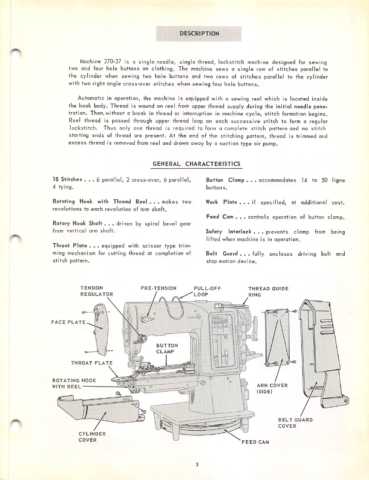
DESCRIPTION
Machine
two and
the
cylinder
with tworight angle cross-over stitches
270-37
four
hole buttons on clothing. The
when
is a single needle, single thread, lockstitch
sewing
two
hole
buttons
when
machine
and
two
sewing
sews a single
rows
of stitches parallel to the
four
hole buttons.
machine
Automatic in operation, the machine is equipped with a sewing reel which is located inside
the
hook
body.
Threadiswound
tration. Then,without a break in thread or interruptioninmachine
Reel
thread is passed
through
lockstitch. Thus only one thread is required to
on reel
upper
from
thread
upper
thread
supply
during
cycle, stitch
loop
on each successive stitch to
form
a complete stitch pattern and no stitch
starting ends of thread are present. At the end of the stitching pattern, thread is
excess thread is
18 Stitches
4 tying.
Rotating
revolutionstoeach
Rotary Hook
from
vertical
...
Hook with
Shaft,
arm
removed
from
reel and
GENERAL
drawn
CHARACTERISTICS
6 parallel, 2 cross-over, 6 parallel,
Thread
revolution
Reel
of arm
. . .
shaft.
makes
two
, . driven by spiral bevel gear
shaft.
away by a suction type air
Button Clomp . . , accommodates 14 to 50 ligne
buttons.
Work
Plate
...
if specified, at additional cost.
Feed
Cam . . . controls operation of button clamp.
Safety Interlock . . . prevents clamp
lifted when machine is in operation.
Throat Plate . . . equipped with scissor type trim
ming mechanism for cutting thread at completion of
stitch
pattern.
Belt
Guard . . . fully
stop
motion
device.
designed
row
of stitches parallel to
for
the Initial needle pene
formation
form
a regular
trimmed
pump.
encloses
driving belt and
sewing
cylinder
begins.
and
from
being
FACE
ROTATING
WITH
PLATE
THROAT
REEL
TENSION
REGULATOR
PLATE
HOOK
CYLINDER
COVER
PRE-TENSION
BUTTON
CLAMP
PULL-OFF
LOOP
THREAD
RING
r.
GUIDE
\
ARM
COVER
(SIDE)
BELT
GUARD
COVER
FEED
CAM
BELT
COVER
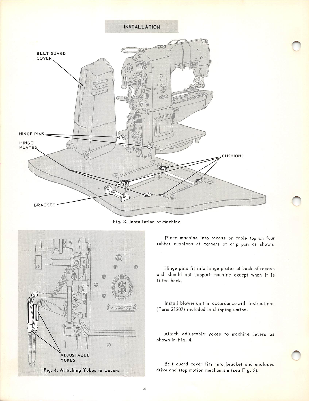
INSTALLATION
GUARD
HIHGE
HINGE
PLATES
PINS
BRACKET
Fig.3.InstallationofMachine
Place
rubber
r
cushions at corners of drip pan as
Hinge pins fit into hinge plates at back of
and should not support machine except
tilted
back.
machine into
recess
GUSH
ONS
on table top on four
when
shown.
recess
it is
(Co
Install
(Form 21207) included in shipping carton.
blower
unitinaccordancewith
Attach adjustable yokes to machine levers as
shown in Fig. 4.
ADJUSTABLE
YOKES
Fig.4.Attaching
YokestoLevers
Belt
guard cover
drive and stop
motion
fits
mechanism (see Fig. 3).
into
bracket
instructions
and
encloses
or
is
on
fabric.
Doily
For
best
"Type
desired
Core
results,
D".
"Type
use
SINGER*
Oil
"Type
D" Oil Is used when on oil
which will produce a minimum of
LUBRICATION
B"
stain
On new
machines
and
machines
Installed
after
several weeks of idleness, needle bar and take-up
linkage should be oiled by hand before using. The
residual lubricant may have congealed or dis
appeared
entirely.
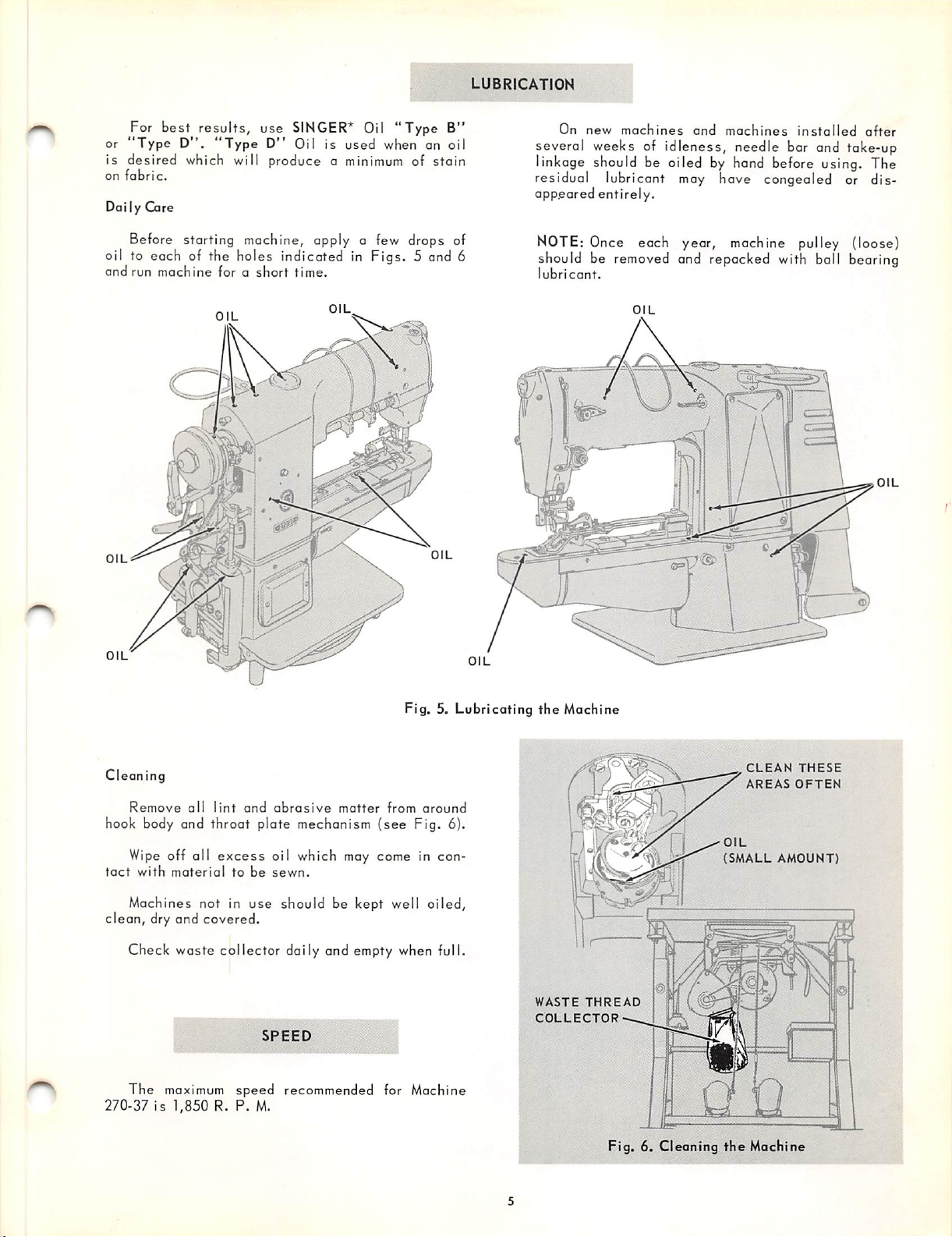
Before starting machine, apply a few drops of
oil to each of the holes indicated in Figs. 5 end 6
and
run
machine
OIL
OIL
forashort
OIL
time.
OIL
OIL
NOTE: Once each year, machine pulley (loose)
should be removed and repacked with ball bearing
lubricant.
OIL
OIL
OIL
Cl
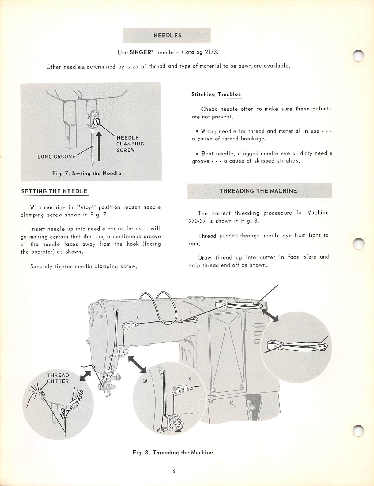
eaning
Remove
hook body and throat plate mechanism
Wipe off all
tact
with
Machines not in
all
material
lint
and
excess
tobesewn.
use
abrasive
matter
from
(see
oil which may come in con
should be kept well
clean, dry and covered.
Check waste collector daily and empty when full.
SPEED
The
maximum
270-37 is 1,850 R. P.
speed
M.
recommended for Machine
Fig. 5.
around
Fig. 6).
oiled,
Lubricating
the
Machine
WASTE
COLLECTOR
THREAD
Fig. 6. Cleaning
1
CLEAN
AREAS
OIL
(SMALL
the
Machine
THESE
OFTEN
AMOUNT)
Other
needles, determined
NEEDLES
Use
SINGER*
by
size of thread and type of material to be sewn,are available.
needle—Catalog
2173.
NEEDLE
CLAMPING
SCREW
LONG
GROOVE
Fig.
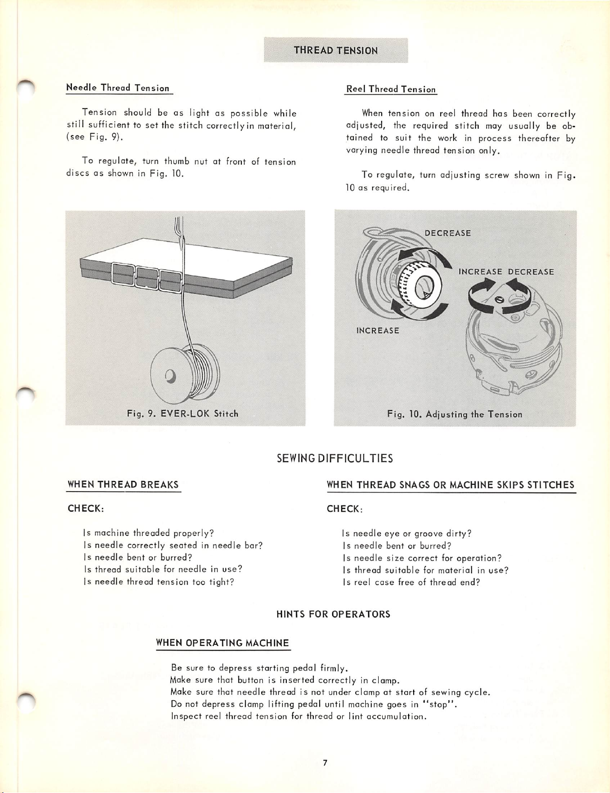
SETTING
With
clamping
7. Setting
THE
NEEDLE
machine in
screw
shown in
"stop"
the
Needle
position loosen needle
Fig.
7.
Insert needle up into needle bar as far as it will
go making certain that the single continuous groove
of
the
needle
the
operator)asshown.
Securely
faces
tighten
away from the hook (facing
needle
clamping
screw.
Stitching
are
•
a
cause
Troubles
Check
not
Wrong
needle
present.
oftentomake
sure
needle for thread and material in use • - -
of thread
breakage.
these
• Bent needle, clogged needle eye or dirty needle
groove - - - a cause of skipped
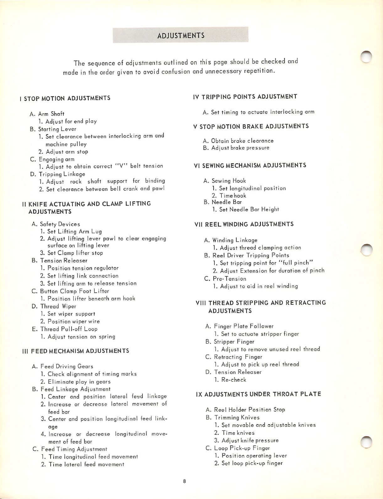
THREADING
THE
The correct threading proceedure for
270-37
rear.
is shown in
Thread
Draw
passes
thread up into cutter in face plate and
Fig.
8.
through needle eye
stitches.
MACHINE
from
Machine
front to
snip thread end off as shown.
defects
THREAD
CUTTER
Fig. 8. Threading
the
Machine
THREAD
TENSION
Needle
Thread
Tension
Tension should be
as
light as
possible
while
still sufficient to set the stitch correctlyin material,
(see
Fig.
9).
To
regulate,
discsasshown in pig. 10.
turn thumb nut at front of
tension
Reel
Thread
When
Tension
tension on reel thread has been correctly
adjusted, the required stitch may usually be ob
tained to suit the work in process thereafter by
varying
10 as required.
needle
thread
tension
only.
To regulate, turn adjusting screw
DECREASE
INCREASE
INCREASE
showninpig.
DECREASE
0
Fig.
9. EYER-LOK Stitch
WHEN
THREAD
CHECK:
BREAKS
Is machine threaded properly?
Is
Is
Is
Is
needle
needle
thread
needle
correctly
bentorburred?
suitoble
thread
seatedinneedle
for
tension
WHEN
Be sure to
Make
Make sure that
Do not
Inspect
SEWING
DIFFICULTIES
WHEN
THREAD
CHECK:
Is needle
bar?
Is
needle
Is needle
needle
in
use?
too
tight?
OPERATING
depress
HINTS
MACHINE
FOR
starting pedal firmly.
Is
thread
Is
reel
OPERATORS
sure that button is inserted correctly in clamp.
depress
reel thread
needle
clamp lifting pedal until machine goes in
thread is not under clamp at
tension
for thread or lint
Fig, 10. Adjusting
SNAGS
eye
or groove dirty?
bentorburred?
size
correct for operation?
suitable
cose
freeofthread
start
accumulation.
OR
MACHINE
for
material
of sewing
"stop".
the
end?
cycle.
Tension
in
use?
SKIPS
STITCHES
STOP
MOTION
1"he
sequenceofadjustments
madeinthe
ADJUSTMENTS
order
giventoovoid
ADJUSTMENTS
outlinedonthis
confusion
and
IV
page
unnecessary
TRIPPING
shouldbechecked
repetition.
POINTS
ADJUSTMENT
and
A.
Arm
Shaft
1. Adjust for end ploy
B. Starting
1. Set
2.
C. Engaging arm
1. Adjust to obtain correct
D.
Tripping
1. Adjust
2. Set
II
KNIFE
ADJUSTMENTS
Lever
clearance
machine pulley
Adjust
arm
stop
Linkage
rock
clearance
ACTUATING
between interlocking arm and
"V"
shaft support
between bell crank and pawl
AND
CLAMP
A. Safety Devices
1. Set
Lifting
Arm Lug
2. Adjust lifting lever pawl to clear engaging
surface
3. Set Clamp lifter
B.
Tension
1.
Position
2. Set lifting link
3. Set lifting arm to
on lifting
Releaser
tension
lever
stop
regulator
connection
release
tension
C. Button Clamp Foot Lifter
1.
D.
Position
Thread
Wiper
lifter
beneath
arm
hook
1. Set wiper support
2.
Position
E.
Thread
1.
Adjust
III
FEED
MECHANISM
A.
Feed
Pull-off
tension
Driving
wiper
wire
Loop
on
ADJUSTMENTS
Gears
spring
1. Check alignment of timing marks
2.
Eliminate
B.
Feed
Linkage
1. Center and
2.
Increase
feed
bar
play in
Adjustment
position
or
decrease
gears
lateral fevd linkage
lateral
3. Center and position longitudinal feed link
age
4.
C.
Feed
Increase
mentoffeed
Timing
or
decrease
bar
Adjustment
longitudinal move
1. Time longitudinal feed movement
2.
Time
lateral
feed
movement
belt tension
for
binding
LIFTING
movement of
A. Set timing to
V
STOP
MOTION
A.
VI
SEWING
B.
Obtain
Adjust
brake
brake
MECHANISM
A. Sewing Hook
1. Set longitudinal position
2.
Time
hook
B.
VII
Needle
1. Set
REEL
Bar
Needle
WINDING
A. Winding Linkage
1. Adjust thread clamping action
B. Reel Driver Tripping
1. Set tripping point for
2. Adjust Extension
C.
Pre-Tension
1. Adjust to aid in reel winding
VIII
THREAD
ADJUSTMENTS
A. Finger
1. Set to
B. Stripper
STRIPPING
Plate
actuate
Finger
1. Adjust to
C.
Retracting
1. Adjust to pick up reel thread
D.
Tension
1.
IX
ADJUSTMENTS
A.
Reel
B. Trimming
1. Set movable and
2.
3. Adjust knife
C.
Loop
1.
2. Set loop pick-up finger
Releaser
Re-check
Holder
Time
knives
Pick-up
Position
Knives
actuate
BRAKE
ADJUSTMENTS
clearance
pressure
ADJUSTMENTS
Bar
Height
ADJUSTMENTS
for
Follower
stripper finger
remove
Finger
UNDER
Position
operating
unused reel thread
adjustable
pressure
Finger
interlocking arm
Points
"full
pinch
duration of pinch
AND
RETRACTING
THROAT
Stop
lever
PLATE
knives