

Singer 256 Service Manual
^ ^
Form
(265)
21222
SERVICE
SINGER
ELECTRO-MECHANICAL
USED
WITH
MACHINES
MANUAL
SEQUENTIAL
OF
CLASS
DEVICES
256
Four
• A
TrademarkofThe
SINGER
Buttonhole
Copyright © 1965by The
Copyright under International Copyright Union
All Rights Reserved under Inter-American Copyright Union
COMPANY
THE
Sewing
SINGER
Units
and
COMPANY
Singer
One
Company
Operator
PrintedinU.S.A.
CONTENTS
DESCRIPTION
INSTALLATION
LUBRICATION
PREPARATION
BUTTONHOLE
SIMPLE
ADJUSTMENTS
FOR
USE
SEWING
4-8
10
11
12-13
3
TROUBLE
NOTES
9
SCHEMATIC
GLOSSARY OF ELECTRICAL SYMBOLS 30
WIRING
PARTS
SHOOTING
AND MEMORANDA
DIAGRAM
DIAGRAM
LIST ANDCHART
(Rear
20-27
28
29
31
of Book)
SEQUENCE OF OPERATIONS AND FUNCTIONS OF ASSOCIATED ELECTRICAL CIRCUITS 14-19
INDEX
Power
Adjustments 7, 8, 12, 13
Air Gop (Clutch Adjustment) 13, 25
Auto-Stoft Button 11, 16
Base
Top
Plate
5, 7
Bearings (Lubrication) 9
Belt
Installation
Belt,
Tension
Belt
Tightener
Bobbin
Brocket
Bobbin, Empty 11, 18, 19
Broke, Camshaft (Adjustment) 13
Buttonhole Completion
(After Interruption) 12, 21
Buttonholes,
Number of 10, 13
Buttonhole Spacing 3, 12, 24, 25
Cabinet Door, Closing 11
Clomp
Check
Clomp
Lift
Clomp Lifting Coble 7
Clomp Lifting Cam 7
Plate
Cloth
(Installation) 8
Cloth Stop 11
Contactor
Counter
Counter
Arrow
15, 20
Counterweight 19
Cylinder 24
Cylinder
Pressure
Cycling Switch, Actuating Lever 6, 26
Dial-Stop Setting 10
Drive-Start
Button
10, 14
Emergency Stop Button 10, 15
Extension, Thread Cutting Lever 7
Fuse
Gripper 11, 21
Gripper Chain 9
Gripper Chain Sprocket 9, 19, 21
Gripper Index 24
Gripper
Jaws
Gripper
Lever
Gripper Slide 24
Gripper
Slide
Block 19
Gripper Slide Roils 9, 24
Gripper Track 9
Hond
Ratchet
Lever
Hilliord
Clutch
Hilliord
Clutch,
Hinge
Bracket
Lubrication 9
Impulse Counter 17
Impulse Count Switch .18
Indexing Cam 17
8
Indexing Com Shaft 16, 17
8
Index Gripper Button 22
8
Index
Reset
10
Indexing Stop Switch Bracket Slide 22
Indicator
Button
Bulb
Interlocking Stop Rod 10
Knife 3, 11, 23
Bar
Knife
Lever, Trip 17
Lubricotion
Machine
7
Machine
Machine
Machine
Base
Bed
Belt
Guord
7
Machine Driving Belt 8
MochineHinge Connection Bracket 5
Mochine
Lubrication
Machine
Rest
3
Machine Speed 10
11
Magnetic Clutch 10, 15
Position
Magnetic Clutch, Cleaning 25
Magnetic
24
Magnetic Clutch,
Clutch
Lubrication
Testing
Magnetic Motor Starter 15
Main
Fuse
Main
Power
Switch
Manuol Starting Lever 6, 12
Microswitch
20
Motor 3, 8, 9
Motor Alignment 8
Belt
Lubrication
Bar
11
11
Motor Driving
Motor
Needle
Needle
Needle Threading 10
Oiling (See Lubrication) 9, 10
Overload
Petcock
12
Switch
17,
9, 10
9, 10
10, 14
21, 25
9, 10, 14
16, 17
18
5
22
20
23
3
5
5
5
9
20
8
9
10
10
15
24
Cord
Power
Switches
Pulley
Reductor
Reposi'tion
Reset
Bor
Rest
Position
Gorment
8,
11, 12, 21
Safety Device, Clamp Lifting 6
Safety Precautions 10, 11, 15
Sewing Buttonholes 11
Sewing Machine Head 5
Solenoid .17, 23, 27
Spacing between Buttonholes
(Adjustment) 3, 12, 24, 25
Spacing between Buttonholes and
Garment Edge (Adjustment) 3, 12
Spacing Com (Adjustment) 12
Speed 10
Starting Button 3
Storting
Lever
Start
Lever
Push-Rod 6
(Manual) 6
Stop Bar 16
Stop Cam 10
Stop Dial 10
Stop, Emergency 10
Stop Motion 10
Stop Motion Interlocking Rod 10
Stop Notch 10
Position
Stop
Switch
Tension
Tension,
Thermal
Thread
Belt
Overload
Switch
7, 10
Thread, Breaking 12
Thread Cutting Lever 7
Threading 10
Tightening Belt 8
Trip Cam 6
Trip
Lever
Trip Rod 6
Upper Cloth
Upper Cloth
Work
Plate
Plate
Assembly 8
Clomp 10, 11
20
10
8
9
20
14
13
8
8
20
10
6
3
TO
ALL
WHOM IT MAY
The
improper
(all
of which ore duly
in any way
placing
whatsoever
CONCERN:
or renewal of
Registered
outside
Trademarks)
a SINGER
the
Trodemork SINGER* or any
on any
machine
factory
or on
outhorized
that
SINGER
other
of the
has
been
repaired,
agencyisforbidden.
TrademarksofThe
rebuilt,
Singer Company
reconditioned,oraltered
j:.
'j • '
L,
Electro-Mechanical
to
automatically
The spacing governs the
which
canbesewninone
A complete unit consists of a steel cabinet
houses the
ment of the garment. Top surface of cabinet
table
panel.
Com
sewing machine.
which
actuated
mechanism
supportsasewing
GENERAL
space
required
mechanism
Sequential
buttonhole
number
cycling
for
machine
FEATURES
controls operation of
Devices
sewingina
of buttonholes
ofthe
unit.
the
automatic
andacontrol
are
designed
garment.
which
move
forms
Electrical switches control operation of entire
device.
G>ntrol panel
contains
electrical
equipment
neces
sary to coordinate control circuits. Panel is equipped
with thermal-overload
protection.
With equal
cottons, cotton and synthetic blends, 100%
and
silks.
A counter automatically
bin thread runs out. Red Indicator Light informs opera
tor of
reason
If
needle
matically prevented
a
tion is automatically stopped.
Knives available will cut buttonholes
5/8"
and
buttonholes
At completion of each buttonholing
clomp is automatically returned to open
tion (ready to accept new work).
for
3/4"
5/8"
ease,
stoppage.
thread
machine
breaks,
from
handles
stops
machine before bob
buttonhole knife is auto
cutting buttonhole and opera
long. Machine regularly fitted to cut
long.
cycle,
resin-finished
3/8",
"start"
Convenient feeding and receiving racks simplify
loading and unloading of work.
Operation of each unit requires little more than
placing
removing
work
under clamp, pressing starting button and
work
when cycle is completed.
synthetics
1/2",
indexing
posi
A Series 38 Motor drives sewing machine. Indexing
Unit is
ducer. Orders for motor must specify correct voltage,
cycles
257000 is designed for
Machine
knownasMachine
Machine
also
driven by this motor through Speed-Re-
and
phase
required.
SPECIAL
ELECTRO-MECHANICAL
71-201.
256W1
Entire automatic buttonholing unit is
256W1.
sequentially positions buttonholes
FEATURES
SEQUENTIAL
use
with Buttonhole Sewing
DEVICE
parallel to edge of garment in accordance with a pre
determined spacing. Buttonholes con be aligned
3/8
inch to 1 inch from edge of facing.
The
machine
that buttonholes are located vertically. From 3 to 7
buttonholes con be sewn in one
positions
and feeds
cycle,
the
garment so
depending upon
from
the desired spacing within the machine's travel limit
of19inches.
Spacing between buttonholes is adjustable
inches
Feed
to 5)4
wheels
inches
opart.
available
for 100, 120, 150
from
and
180
stitches per buttonhole. Machine regularly supplied
with feed wheel for 120
stitches
per buttonhole.
The sewing head. Machine 71-201, has an oscil
lating shuttle and a
Instructions for servicing Machine 71-201
in
Form
2174W.
In addition to the sequential device, the sewing
head and other units already mentioned. Machine
includesanadjustable
winder and a light fixture.
ELECTRO-MECHANICAL
maximum
upper cloth
speed of 2000 R. P.
plate,
SEQUENTIAL
257464 is designed for use with Buttonhole Sewing
Machine 271K201.
is
knownasMachine
Machine 256-5 is
256W1,
2)4
The sewing head.
cated rotary sewing
maximum
vicing
and K6640,
except
speed is 3000 R. P.
Machine
available
Entire
for sewing head in
automatic buttonholing unit
256-5.
essentially
Machine
hook
and a two-speed drive. Its
271K201
are contained in
upon
request.
the same as Machine
use.
271K201,
M.
Instructions for ser
are
contained
256W1
a thread un
DEVICE
has a lubri
Forms
21303
M.
A
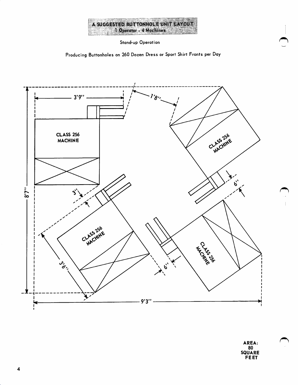
SUGO|E$f
|)S);
BUTTQN^^
Producing
CLASS
MACHINE
256
Stand-up
Buttonholeson260
Operation
Dozen
Dress or
Sport
Shirt
Fronts per
Day
AREA:
80
SQUARE
FEET
INSTALLATION
Machines of
assembled, ready for operation.
Class
256 are shipped completely
When
these
units have
been disassembled, the following instructions apply
to
their
reassembly.
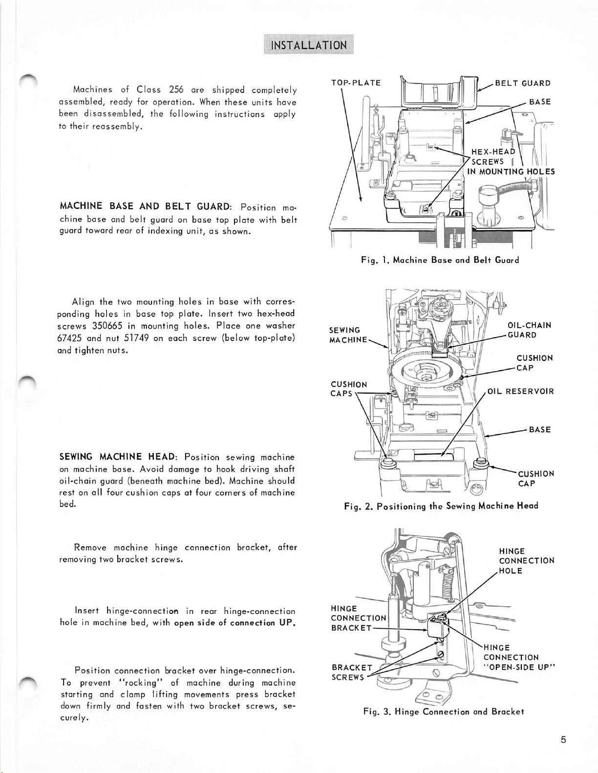
MACHINE BASE AND
BELT
GUARD:
Position
ma
chine base and belt guard on base top plate with belt
guard toward rear of indexing unit,asshown.
Align the two mounting holes in
base
ponding holes in
screws
350665 in mounting
67425 and nut 51749 on
and
tighten
nuts.
top plate. Insert two hex-head
each
holes.
base
with corres
Place
one washer
screw (below top-plate)
TOP-PLATE
SEWING
MACHINE
Fig.
1. Machine
J
HEX-HEAD\lf(\
.VSCREWS
^INMOUNTING
Base
and
Belt
BELT
Guard
OIL-CHAIN
GUARD
—
GUARD
I \
HOLES
CUSHION
CAP
IWl
SEWING
on machine
oil-chain
MACHINE HEAD:
base.
Avoid damage to hook driving shaft
Position
sewing machine
guard (beneath machine bed). Machine should
rest on all four cushion caps at four corners of machine
bed.
Remove machine hinge connection bracket, after
removing two
bracket
screws.
Insert hinge-connection in rear hinge-connection
hole in machine bed, with open side of connection UP.
Position
To prevent
starting
down firmly and fasten with two bracket
curely.
connection
"rocking"
bracket
over
hinge-connection.
of machine during machine
and clamp lifting movements
press
screws,
bracket
se
CUSHION
CAPS\—
OIL
Fig. 2. Positioning the Sewing Machine Head
HINGE
CONNECTION
.HOLE
HINGE
CONNECTION
BRACKET
'HINGE
CONNECTION
BRACKET
SCREWS
II
Fig.3.Hinge
<3
Connection
"OPEN-SIDE
and
Bracket
RESERVOIR
CUSHION
CAP
UP'
INSTALLATION (Continued)
DRIVING
SOCKET
SCREWS
RELEASING
LEVER
BRACKET
LEVER
1/8"
TO
CLEARANCE
Fig.4.Cycling
TRIP
LEVER
BRACKET
ADJUSTING
SCREW
NUT
MANUAL
START-
LEVER
COLLAR.
SET
SCREW
PUSH
ROD
BRACKET
STUD
1/4"
MACHINE
STARTING
LEVER
TRIP
1/2
HINGE
SCREW
Fig. 5. Manual
Switch
ROD
LEVER
Starting
GUIDE
PIN
Actuating
MACHINE
STARTING
LEVER
^
Start
Lever
BASE
SOCKET
SCREW
LEVER
arm
SOCKET
AND
LEFT
OF
Lever
Push
ACTUATING
LEVER
TOP
Lever
START-
BRACKET
MOUNTING
BLOCK
SPRING
WASHER
MOUNTING
BRACKET
SCREWS
LOCK
EDGE
BASE
and
Rod
PLATE
MANUAL
LEVER
WASHERS
PLATE
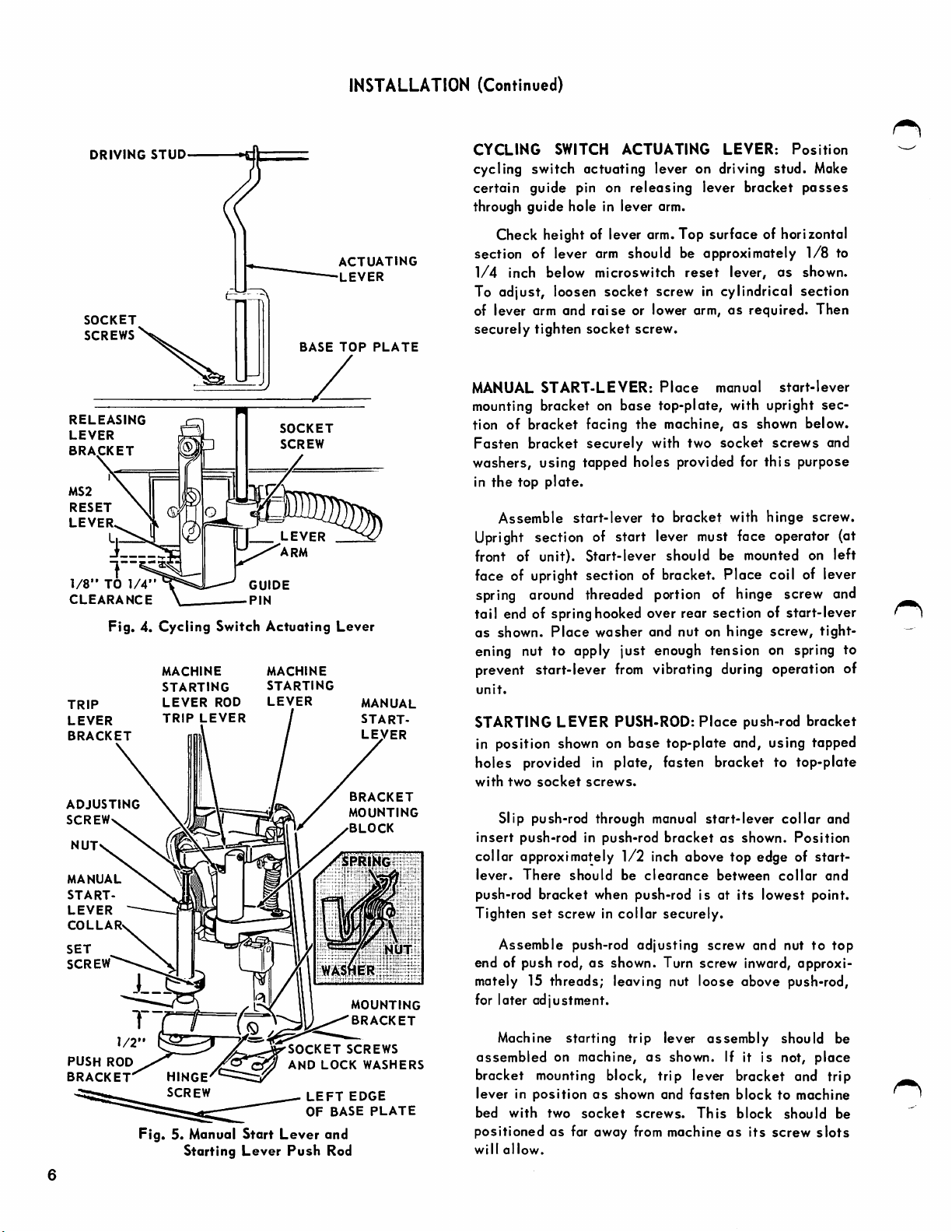
CYCLING
cycling switch actuating lever on driving stud.
certain guide pin on releasing lever bracket
SWITCH
ACTUATING
LEVER:
Position
Make
passes
through guide hole in lever arm.
Check height of lever arm.Top surface of horizontal
section of lever arm should be approximately
1/4
inch below microswitch
reset
lever,
as
1/8
shown.
to
To adjust, loosen socket screw in cylindrical sectian
of lever arm and
securely tighten
MANUAL
START-LEVER:
raise
or lower arm,asrequired.
socket
screw.
Place
manual
Then
start-lever
mounting bracket on base top-plate, with upright sec
as
tion of bracket facing the machine,
shown below.
Fasten bracket securely with two socket screws and
this
hinge
purpose
screw.
washers, using tapped holes provided for
in
the
top
plate.
Assemble
start-lever
to
bracket
with
Upright section of start lever must face operator (at
front of unit). Start-lever should be mounted on left
face of upright section of bracket. Place coil of lever
spring
around
threaded
portion
of hinge screw and
tail end of spring hooked over rear section of start-lever
as shown.
Place
washer
and nut on hinge
screw,
tight
ening nut to apply just enough tension on spring to
prevent start-lever
unit.
STARTING LEVER PUSH-ROD:
from
vibrating during operation of
Place
push-rod bracket
in position shown on base top-plate and, using tapped
holes provided in plate, fasten bracket to top-plate
with
two
socket
Slip push-rod through manual start-lever
insert
push-rod in push-rod
collar approximately
lever.
There
push-rod bracket when push-rod is at
Tighten
set
Assemble
screws.
bracket
1/2
inch above top edge of start-
should
be
clearance
screw in collar securely.
push-rod
adjusting
screw and nuttotop
as shown.
between
its
lowest point.
collar
Position
collar
and
and
end of push rod,asshown. Turn screw inward, approxi
mately 15 threads; leaving nut loose above push-rod,
for later adjustment.
Machine starting trip lever assembly should be
assembled
on machine,
as
shown. If it is not,
place
bracket mounting block, trip lever bracket and trip
lever in
bed
positionedasfar away from machineasits
will
positionasshown and
with
two
socket
allow.
screws.
fasten
This
block
block
to machine
should
screw
slots
be
Adjust the push-rod adjusting screw so that It will
cause the trip lever to engage the
lever
in the "RUN" position,
1/32
inch
unit's
overthrow
machine
starting
when
lever.
actuated
ment is obtained tighten adjusting screw nut
Fig. 5, to
retain
this
setting.
machine
providingonadditional
by
the
When
correct adjust
shown
starting
indexing
in
(MOUNTING
HIGH
HOLE
POSITION
BELOW
CENTERLINE)
CLAMP
is in
machine.)
LIFTING
"stop"
CABLE:
Make
position. (See Service
certain
Manual
that
machine
for sewing
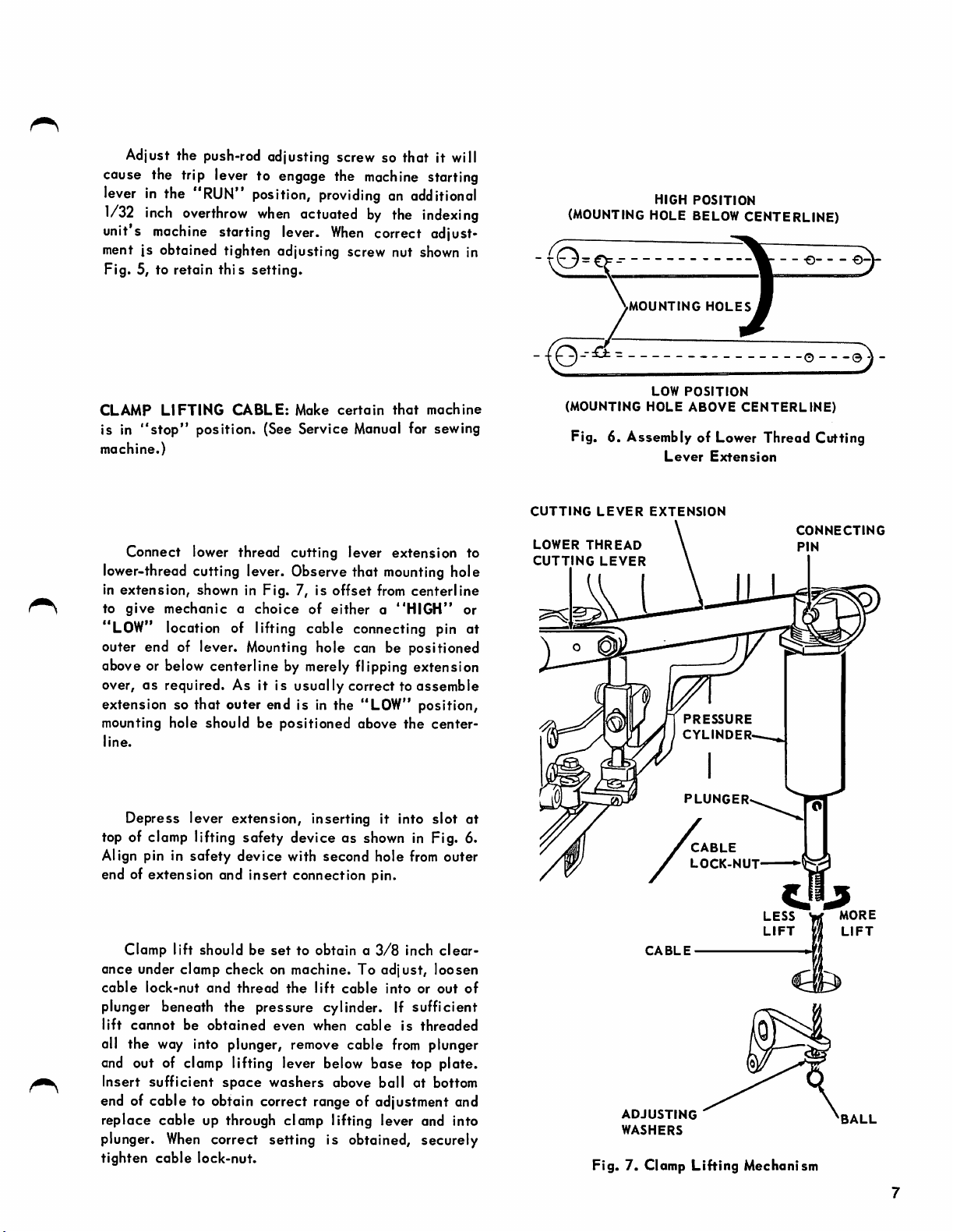
Connect lower thread cutting lever extension to
lower-thread cutting lever. Observe that
in extension, shown in Fig. 7, is
to
give
mechanicachoice
offset
of
eithera"HIGH"
mounting
hole
from center line
"LOW" location of lifting coble connecting pin at
outer end of lever. Mounting hole con be positioned
above or below centerline by merely flipping extension
over,OSrequired. As it is usually correct to assemble
extension so that outer end is in the "LOW" position,
mounting hole should be positioned above the center-
line.
(MOUNTING
MOUNTING
LOW
HOLE
HOLES
POSITION
ABOVE
CENTERLINE)
Fig. 6. Assembly of Lower Thread Cutting
Lever
Extension
CUTTING
LOWER
CUTTING
or
LEVER
THREAD
LEVER
EXTENSION
CONNECTING
PIN
PRESSURE
CYLINDER
Depress lever extension, inserting it into
slot
at
top of clomp lifting safety device as shown in Fig. 6.
Align pin in safety device with second hole
from
outer
end of extension and insert connection pin.
Clomp lift should be
ance under clamp check on machine. To
cable
lock-nut
and
thread
set
to obtain a
the
lift
cable
3/8
inch
adjust,
intoorout
clear
loosen
of
plunger beneath the pressure cylinder. If sufficient
lift
cannot
all the way into plunger, remove coble
and out of clomp lifting lever below
Insert
be
sufficient
obtained
space
even
washers
when
cable
is
threaded
from
base
top plate.
above boll at bottom
plunger
end of coble to obtain correct range of adjustment and
Fig.
ADJUSTING
WASHERS
7. Clomp
replace cable up through clamp lifting lever and into
plunger.
tighten
When
cable
correct setting is obtained, securely
lock-nut.
PLUNGER
CABLE
LOCK-NUT
Lifting
LESS
LIFT
Mechanism
W
i[j
MORE
LIFT
BALL
INSTALLATION (Continued)
DRIVING
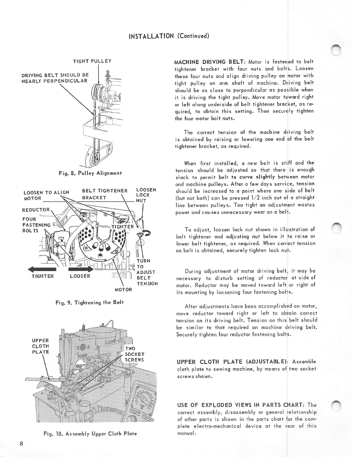
NEARLY
BELT
SHOULD
PERPENDICULAR
Fig. 8,
LOOSENTOALIGN
MOTOR
REDUCTORv
FOUR
FASTENING
BOLTS
^
K ^
TIGHT
BE
Pulley
BELT
BRACKET
PULLEY
Alignment
TIGHTEN^
TIGHTER
\
LOOSEN
\\l
MACHINE DRIVING
tightener bracket
these four nuts and olign driving pulley on
tight
pulley
should be as
it is driving the tight pulley.
on
close
BELT:
with
four
Motor is
nuts
fastened
and
bolts.
Loosen
motor
arm
shaft of
machine.
Driving
to perpendicular as possible when
Move
motor
toword right
to
belt
with
belt
or left along underside of belt tightener bracket,asre
quired, to obtain this setting. Then securely tighten
the
four
motor
bolt
nuts.
The correct
is obtoinedbyraising or
tension
of the machine driving belt
lowering
one end of the belt
tightener bracket, as required.
When
first installed, a new belt is stiff and the
tension should be adjusted so that there is enough
stack to
and machine pulleys. After a few days
permit
belt to curve slightly between
service,
motor
tension
should be increosed to a point where one side of belt
(but not both) can be pressed
1/2
inch out of a straight
line between pulleys. Too tight an adjustment wastes
power
and causes unnecessary wear on a belt.
To adjust, loosen lock nut
belt tightener and adjusting nut below it to
lower belt tightener,asrequired.
on belt is obtained, securely tighten lock nut.
shown
When
in illustration of
raise
correct
tension
or
TIGHTER
LOOSER
Fig, 9. Tightening the Belt
UPPER
CLOTH
PLATE
•j
f
]
Fig. 10. Assembly Upper Cloth
TURN
TO
ADJUST
BELT
TENSION
MOTOR
^
SOCKET
SCREWS
Plate
During
adjustment of
motor
driving
belt, it
may
be
necessary to disturb setting of reductor at side of
motor.
its
move reductor toward right or left to obtain correct
Reductor
mounting
maybemoved
toward left or right of
by loosening four fastening bolts.
After adjustments have been accomplished on
motor,
tension on its driving belt. Tension on this belt should
be similar to
that
required on machine driving belt.
Securely tighten four reductor fastening bolts.
UPPER
CLOTH
PLATE
(ADJUSTABLE):
Assemble
cloth plate to sewing machine, by means of two socket
screws
USE
shown.
OF
EXPLODED
VIEWS
IN
PARTS
CHART:
The
correct assembly, disassembly or general relationship
of other ports is shown in the parts chart for the com
at
plete electro-mechanical device
the rear of
this
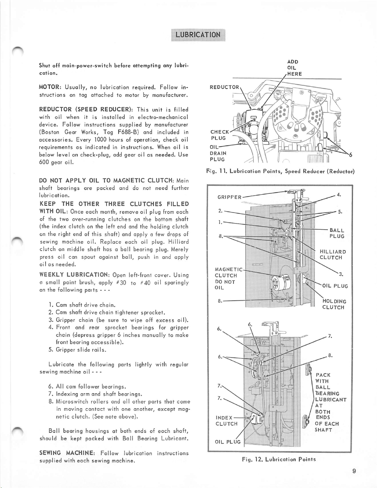
LUBRICATION
Shut off main-power-switch before attempting any lubri
cation.
MOTOR:
structions on tog
REDUCTOR
with
device.
Usucily, no lubrication required. Follow in
oil
(SPEED
when
Follow
attached
it
is
instructions
to motor by manufacturer.
REDUCER):
installed
in
supplied
This
electro-mechanical
by manufacturer
unitisfilled
(Boston Gear Works, Tog F688-B) and included in
accessories.
requirements
Every
as
indicated
lOOO
hours of operotion, check oil
in
instructions.
When oil is
below level on check-plug, odd gear oil as needed. Use
600
gear oi I.
DO
NOT
APPLY
shaft
lubrication.
bearings
KEEP
WITH
THE
OIL: Once each month, remove oil plug
of the two over-running
OIL
are
OTHER
TO
packed
THREE
clutches
MAGNETIC
and do not
CLUTCHES
on the bottom shaft
CLUTCH:
need
from
Main
further
FILLED
each
(the index clutch on the left end and the holding clutch
on the right end of this shaft) and apply a few drops of
sewing machine
oil.
Replace
each
oil plug. Milliard
clutch on middle shaft has a ball bearing plug. Merely
press
oil can
oilasneeded.
WEEKLY
spout
against
boll,
push in and apply
LUBRICATION: Open left-front cover. Using
a small paint brush, apply #30 to #40 oil sparingly
on the following potts • - -
REDUCTOR
CHECK
PLUG
OIL
DRAIN
PLUG
F<g. 11. Lubrication
GRIPPER
MAGNETICCLUTCH
DO
NOT
OIL
Points,
Speed Reducer (Reductor)
ball
PLUG
sun
IrfL
milliard
CLUTCH
OIL
PLUG
1.
Cam
shaft
drive
chain.
2. Cam shaft drive chain tightener sprocket.
3. Gripper chain (be sure to wipe off
excess
oil).
4. Front and rear sprocket bearings for gripper
chain (depress gripper 6 inches manually to make
front bearing
5. Gripper
slide
accessible).
rails.
Lubricate the following parts lightly with regular
sewing machine oil - • -
6. All cam follower
7. Indexing arm and
8. Microswitch
in moving
netic
clutch.
Ball bearing housings at both ends of
rollers
contact
(See
bearings.
shaft
bearings.
and all other parts
with
one
another,
note
above).
that
except
each
come
mag
shaft,
should be kept packed with Ball Bearing Lubricant.
SEWING
supplied with
MACHINE:
each
Follow
lubricati
sewing machine.
on
instructions
INDEX
CLUTCH
OIL
PLUG
^
[y
Fig.
12.
Lubrication
[BEARING
/LUBRICANT
Points
HOLDING
CLUTCH
PACK
WITH
BALL
AT
BOTH
ENDS
OF
SHAFT
EACH
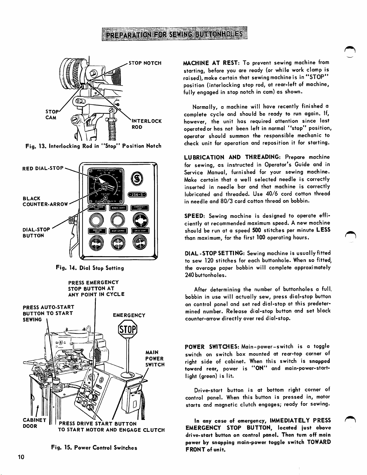
STOP
NOTCH
MACHINE
starting,
raised),
AT REST; To prevent sewing machine
before
make
you
ore
certain that
position (interlocking stop
fully
engaged in stop notch in
ready
(or
sewing
rod,
at rear-left of machine,
com)asshown.
while
machine
from
work
clamp
is in"STOP"
is
STOP
Fig. 13. Interlocking Rod in
RED
DIAL-STOP
BLACK
COUNTER-ARROW
DIAL-STOP
BUTTON
Fig. 14. Did Stop Setting
PRESS
EMERGENCY
STOP
BUTTON
ANY
POINTINCYCLE
PRESS
BUTTON
SEWING
AUTO-START
TO
START
"Stop"
(j
AT
EMERGENCY
INTERLOCK
ROD
Position Notch
5^
Normally,amachine
complete
however,
operated
cycle
the unit has required attention since lost
or has
not
operator should
and
summon
will
should
been
left in
the responsible
have
recently
be
readytorun
normal
finished a
again.
If,
"stop" position,
mechanic
to
check unit for operation and reposition it for starting.
AND
LUBRICATION
for
sewing, as instructed in Operator's
THREADING:
Prepare machine
Guide
and in
Service Manual, furnished for your sewing machine.
Make
certain
inserted in
lubricated and
in
needle
SPEED:
ciently at
that
a well
needle
threaded.
and
80/3
cord
Sewing
machine
recommended
selected
bar and
Use
cotton
needleiscorrectly
that
machine is
40/6
cord cotton thread
thread
on bobbin.
is designed to operate effi
maximum
speed. Anew machine
correctly
should be run at a speed 500 stitches per minute LESS
than
maximum,
for the first 100 operating hours,
DIAL-STOP SETTING: Sewing machine is usually fitted
to sew 120
stitches
for each buttonhole.
When
so fitted,
the overage paper bobbin will complete approximately
240
buttonholes.
After determining the
number
of buttonholes a full,
bobbin in use will actually sew, press dial-stop button
on
control
mined
counter-arrow
panel and set red dial-stop at this predeter
number.
Release dial-stop button and set black
directly
over red
dial-stop.
n
MAIN
POWER
SWITCH
POWER
switch on switch box mounted at rear-top corner of
right side of cabinet.
toward rear, power is
SWITCHES:
Main-power-switch is a toggle
light (green) is lit.
Drive-start button is at bottom right corner of
control panel.
When
this button is pressed in,
starts and magnetic clutch engages; ready for sewing.
CABINET
DOOR
PRESS
TO
DRIVE
START
START
MOTOR
AND
BUTTON
ENGAGE
CLUTCH
In any
EMERGENCY STOP BUTTON,
case
of emergency,
drive-start button on control panel. Then turn off main
power by snapping main-power toggle switch
Fig.
15.
Power
Control
10
Switches
FRONTofunit.
When
this switch is
"ON"
snapped
and main-power-start-
motor
IMMEDIATELY
located
PRESS
just
above
TOWARD
 Loading...