

Page 1
Tlrm 20549
r:ev. (557)
SERVICE MANUAL
AND
PARTS LIST
FOR
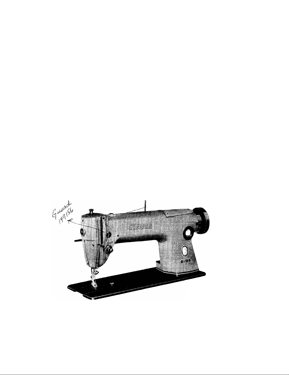
SINGER
MACHINES
OF CLASS 251
SINGLE NEEDLE LOCK STITCH
AUTOMATIC OILING SYSTEM
£275Si?
CAUTION—See that the oil reservoir is filled os instructe.d on page 6 before running the machine, even to test
•A Trade Mark of THE SINGER MANUFACTURING COMPANY
the speed. Special attention is olso called, to the hook lubricating instructions on page 7.
THE SINGER MANUFACTURING COMPANY
Copyright © 1957 by The Singer Manufacturing Company
Printed in U. S. A.
Page 2
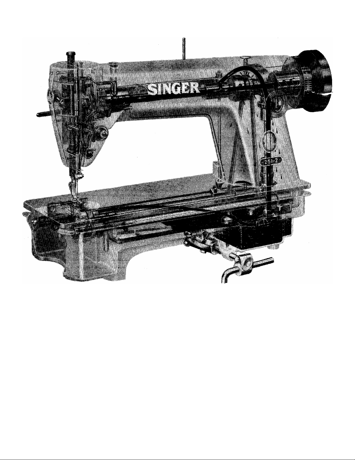
FIG. 2. X-RAY VIEW OF MACHINES OF CLASS 251
(LUBRICATING SYSTEM SHOWN IN SOLID BLACK)
FOREWORD
This book contains complete information covering operation, adjustment,
parts list, attachments and special fittings for Machines of Class 251- Descriptions
and exploded vievYS of all parts assemblies on pages 45 to 194 Inclusive, will be
found helpful when ordering any part of the machine requiring renewal.
Page 3

DESCRIPTION
Machines of Class 251 produce top quality, straight-line, single-needle, lock stitching in fabrics as fine as
ladies' lingerie or as heavy as mens' overcoating.
General Features
Federal Stitch Type #301.
High Speed (see chart on page 4). Maximum speed
dependent upon nature of work and ability of
operator.
Gear driven, lubricated. Rotary Sewing Hook on
horizontal axis makes two revolutions for each stitch.
Upper gears are spiral-bevel. Lower gears are
hypoid-bevel.
Hook Shaft mounted .160 inch forward of vertical
axis of Needle Bar for improved stitch formation.
Drop Feed guided by mounted journal bearings to
prevent side movement of Feed Dog.
Length of stitch determined by a Push-Button Stitch
Regulator on top of machine arm. Regulator includes
Locking Device to prevent changing of stitch length
during machine operation: (For maximum possible
.stitch length, see chart on page 4). Stitch Length Indi
cations on Machine Pulley are in view of operator.
Automatic Lubricating System (see X-Ray View on
opposite page). Centrifugal Pump delivers oil under
pressure from Reservoir to all principal bearings. Oil
wicks lubricate bearing surfaces in head end of ma
chine and return excess oil to Reservoir. Oil Guard
covers entire path of Take-up Lever.
Oil Flow Window, in direct view of operator, reveals
circulation of oil inside machine arm.
Machine Dimensions: Bed length 18-3/4 inches,
width 7 inches. Space at right of Needle 1 1 inches.
Machine Head is supported by Machine Base and
Oil Reservoir, designed to fit the cutout in table.
Machine Pulley 147016. Outside diameter of belt
groove 2.90 inches for 3/8 inch V-belt. Effective diam
eter for 5/16 inch round leather belt is 2-3/8 inches.
When the machine is in operation, the top of the
machine pulley must always turn over toward the
operator.
Knee Lifter, regularly furnished, is an integral part
of the Machine Base and Reservoir.
Page 4

SPECIAL CHARACTERISTICS OF
MACHINES OF CLASS 251
MACHINES (CLASS AND VARIETY)
TYPE OF
MATERIAL
MAXIMUM
SPEEDt
(R.P.M.)
MAXIMUM
STITCH
LENGTH
NEEDLE BAR
STROKE
(Inches)
251-1
Light-Weight
5000
7
per inch
1-9/64
251-2 251-3
Medium-Heavy
to Light-Weight
5000 4300
5-1/2
per inch
1-13/64 1-7/16
Heavy to
Light-Weight
5-1/2
per inch
251-3 (HEAVY)
Extra-Heavy to
Light-Weight
4300
5-1/2
per inch
1-7/16
PRESSER BAR
LIFT
(Inch)
NEEDLES:
CLASS
AND
VARIETY
SIZES
RECOM
MENDED
fDependent upon nature of material and ability of operator.
9/32
88 X 9
8, 9,10,11,12,
13, 14, 16,
17, 18, 19,
20, 21 and 22
5/16
16 X 257
8, 9, 10, 11, 12, 13,
14, 16, 17, 18, 19,
20, 21,22, 23 and
24
3/8
16 X 257
8, 9, 10, 11, 12,
13, 14, 16, 17,
18, 19, 20, 21,
22, 23 and 24
7/16
16 X 261
16, 18, 19, 21,
22 and 23
Page 5
SETTING UP
TABLE
CUT-OUT
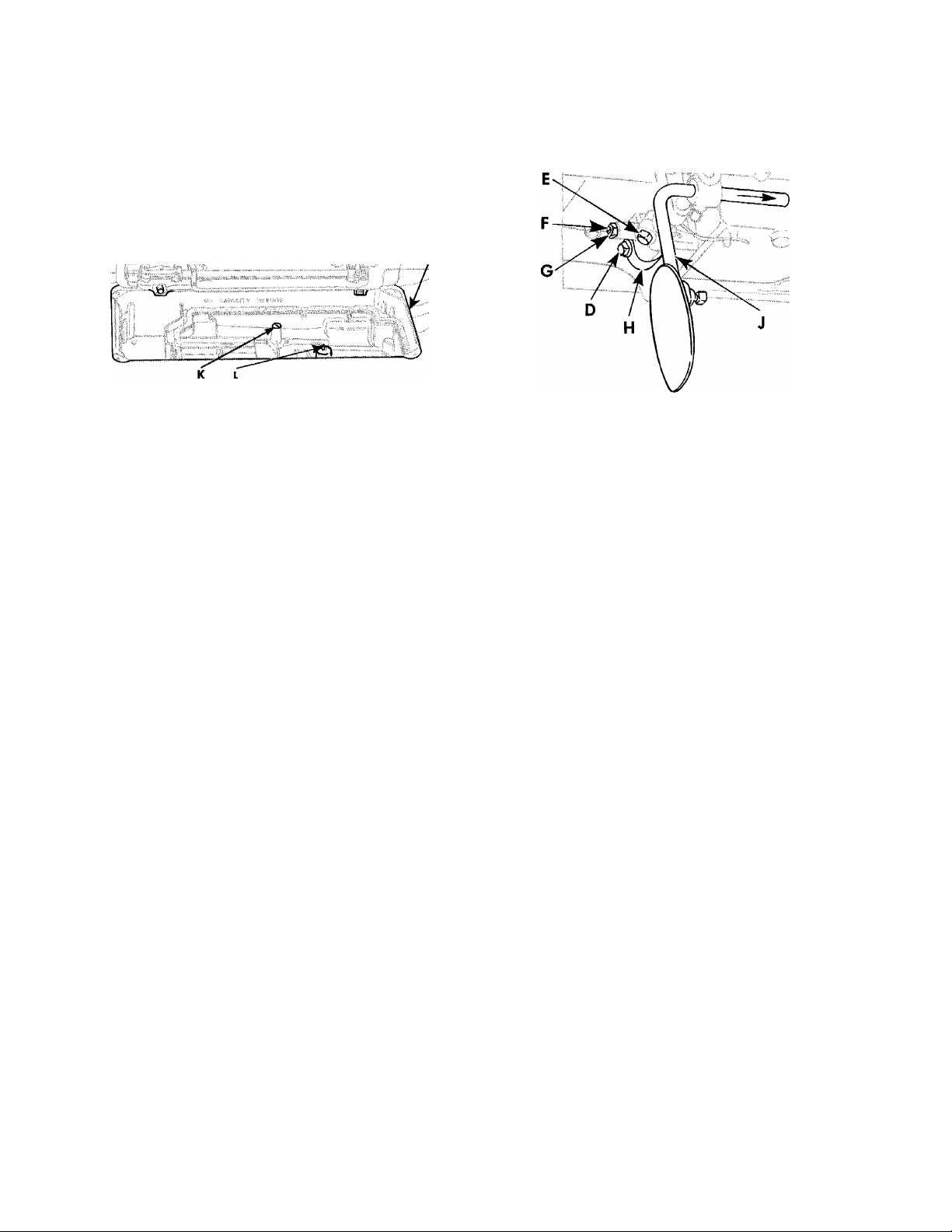
Fig. 3. Installation of Machine
on Base
When shipped, the base is held to the machine by
a single bolt through the bottom of the base. Discard
this bolt and plug the hole by inserting from inside
the base, the special cap screw K, Fig. 3, furnished
with the machine.
The base fits into a standard table cut-out, as shown
in Fig. 3 and rests on the four corners without
fastening.
Rasp the edges of the cutout, if necessary, as the
base must slide in without driving and must be located
so that the machine head does not touch the table
when it is placed on the base.
Use shims on the corners, if necessary, to prevent
the base from rocking. The base should also be level
in both directions so that the oil level will be accurately
indicated by the marks in the base.
See that the plunger L, Fig. 3 is in place inside the
base, before putting the machine on the base.
Fig. 4. Installation of Knee
Lifter on Machine Base
The machine head rests on the cork gasket in the
base and is not fastened. The machine hinges must
not support the head except when it is tilted back.
The knee lifter is shipped assembled to the base,
except for the knee plate and lever J, Fig. 4. After
the base is in position, loosen the set screws D and E,
Fig. 4 and slide the shaft forward to the position
shown in Fig. 4. Attach the knee lifter lever J. Set the
stop screw F so that there is only a little play of the
lifter before it starts to lift the presser bar, then hold
the screw and tighten lock nut G. Set the rear stop dog
H to allow the presser bar to be just raised to its limit
but not enough to permit further strain on the knee
lifter parts or to permit the action of the knee lifter
to lift the machine from its base.
CAUTION:—Before starting the machine, it must be
thoroughly oiled, in accordance with the instructions
on page 6.
The maximum speed recommended for Machines
251-4 and 251-2 is 5000 revol utions per minute and
for Machine 251-3, 4300 revolutions per minute ac
cording to the material being sewn and the type of
work being done. (See chart on opposite page.)
SPEED
It is advisable to operate these machines at a more
moderate speed the first few days, after which they
can be operated at maximum speed.
Page 6

TURN BACK MACHINE
LUBRICATION
NEVER ALLOW
OIL TO FALL
BELOW LOW MARK
Fig. 5. Oil Reservoir
FILL TO
HIGH MARK
Machines of Class 251 have an automatic lubricat
ing system in which oil is circulated by means of a
centrifugal pump from a reservoir in the base. X-Ray
view of machine on page 2 illustrates automatic cir
culation of oil in this machine.
BEFORE STARTING THE MACHINE the oil reservoir
must be filled with "TYPE A" or "TYPE C" OIL, sold
by Singer Sewing Machine Company. "TYPE C" OIL
is used when an oil is desired which will produce a
minimum of stain on fabrics, even after a long period
of storage.
Tip the machine back on its hinges and fill the oil
reservoir as instructed in Fig. 5,
Fig. 6. Oil Flow Window
When in operation, the oil level in the reservoir
should be inspected at least twice a month or as oftei^
as necessary, to keep it from going below the LOW
mark, see Fig. 5, in the reservoir.
CAUTION: Correct lubrication is indicated by a con
tinuous stream of oil passing the oil flow window
while machine is running, as shown in Fig. 6.
Should this oil flow become erratic, STOP the ma
chine and do not run the machine again until the oil
flow has been restored.
At least twice each month check the oil level in the
reservoir.
Never allow oil level to drop below LOW mark,
shown in Fig. 5.
When a machine is NEW or has been idle for several
weeks it is advisable to remove the face plate and oil
the needle bar and take-up bearings. Oil the hook as
sembly by hand and check the oil flow, as instructed
on page 7. The automatic oiling system will function
efficiently, after the first few minutes and continue to
lubricate all bearings.
Oil your bobbin winder occasionally by applying
a few drops of oil to the oil well in bobbin winder,
as shown in Fig. 15, page 12.
See instructions, covering Oil Removing Wick As
sembly, on pages 38 to 41.
Page 7
ADJUSTMENT OF ROTATING HOOK OIL FLOW REGULATOR
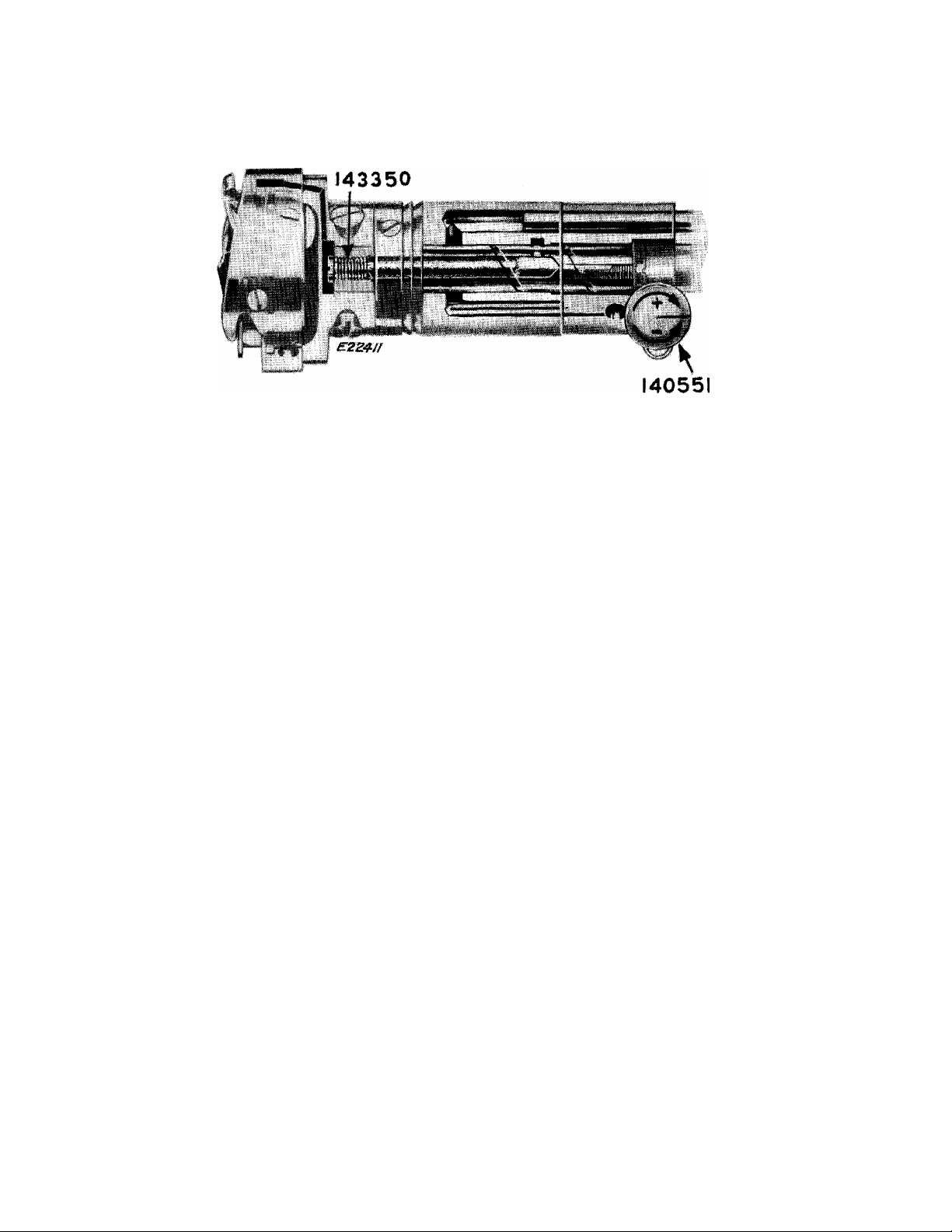
Fig. 7. Oil Flow Regulator in Hook Shaft Bushing
The sewing hook is automatically lubricated. The
flow of oil is controlled by Oil Flow Regulator 140551,
Fig. 7.
The Oil Flow Regulator 140551 is set at the factory
for automatic lubrication of the hook under overage
sewing conditions.
Turn Regulator Thumb Screw (see 140551, Fig. 7)
clockwise to increase the flow of oil to the hook as
indicated by the (-|-) sign under its arrow on the head
of the thumb screw.
HINTS FOR PERFECT OPERATION
If the sewing hook should become excessively warm,
it may be due to an insufficient supply of oil to the
hook (see instructions, above, for adjusting Oil Flow
Regulator).
Keep the oil level in the oil reservoir at the HIGH
mark.
Clean out any lint or other waste around the hook,
around the needle slot in the bobbin case holder
and between the feed rows on the under side of the
throat plate.
Clean out any lint or other foreign matter that may
have collected around oil return passages, particu
larly at oil return hole in rear arm shaft bushing.
Turn Regulator Thumb Screw counterclockwise to
decrease the flow, as indicated by the (~) sign under
its arrow on the head of the thumb screw.
To determine whether the oil is properly flowing
to the hook, withdraw the bed slide and hold a
piece of thin paper under the hook while the machine
runs for ten seconds. There should be a pattern of three
oil sprays on the paper; two light lines on the outside
and one heavier spray in the center. If there is no
trace of oil or an excessive amount of oil on paper,
adjust the Oil Flow Regulator, as instructed above, or
replace the oil filter 143350, Fig. 7, in the head of the
hook shaft, as instructed on page 28.
Always keep the bed slides closed when the ma
chine Is in operation.
Do not run the machine with the presser foot resting
on the feed without some fabric under the presser foot.
Do not run the machine when both bobbin case and
needle are threaded unless there is material under the
presser foot.
Do not try to aid the machine by pulling the fabric
lest you bend the needle. The machine feeds the work
without assistance.
When in operation, the top of the machine pulley
must always turn over toward the operator.
NEVER TOUCH THE STITCH REGULATOR PLUNGER
WHILE THE MACHINE IS RUNNING.
Page 8
NEEDLES
The size of the needle to be used should be deter
mined by the size of the thread which must pass
freely through the eye of the needle. Rough or uneven
thread, or thread which passes with difficulty through
the eye of the needle, will interfere with the successful
use of the machine. (See chart on page 4 to determine
Size as well as Class and Variety of needle required.)
A bent needle may cause the machine to skip
stitches, or it may make it difficult for the operator to
keep a perfectly even margin. In many cases, a run
off will take place.
A hook or burr on the needle point will result in o
finish that looks blurred and when short stitches are
used (20 to 22 per inch), some materials may be cut.
TO SET THE NEEDLE
Check needles often to make sure that defects are
not present.
Orders for needles must specify the Quantity re
quired, the Size number, also the Class and Variety
numbers, separated by an x.
The following is an example of an intelligible order;
"100 No. 16, 88 X 9 Needles."
The best stitching results will be obtained by using
needles sold by Singer Sewing Machine Company.
The above needles are regularly furnished with
nickel finish but are also available with chromium
finish if so ordered.
Turn the machine pulley over toward the operator
until the needle bar moves to its highest point.
After loosening needle set screw, insert needle UP
into needle bar AS FAR AS IT WILL GO, as instructed
in Fig, 8.
The single continuous groove of the needle MUST
face the left end of the machine, as shown in Fig. 8.
Securely tighten needle set screw.
NOTE: The needle is held in place, in Machines 251-2
and 251-3, by means of a needle clamp, instead of the
set screw in needle bar shown in Fig. 8.
MOVE TO
-^-HIGHEST '
POINT
loosen
SCREW
INSERT
NEEDLE UP
AS FAR AS
POSSIBLE
Fig. 8. Setting the Needle
(Mochine 251-1 )
Page 9
THREAD
On Machines of Class 251- use only left twist
thread in the needle. Either right or left twist thread
can be used in the bobbin.
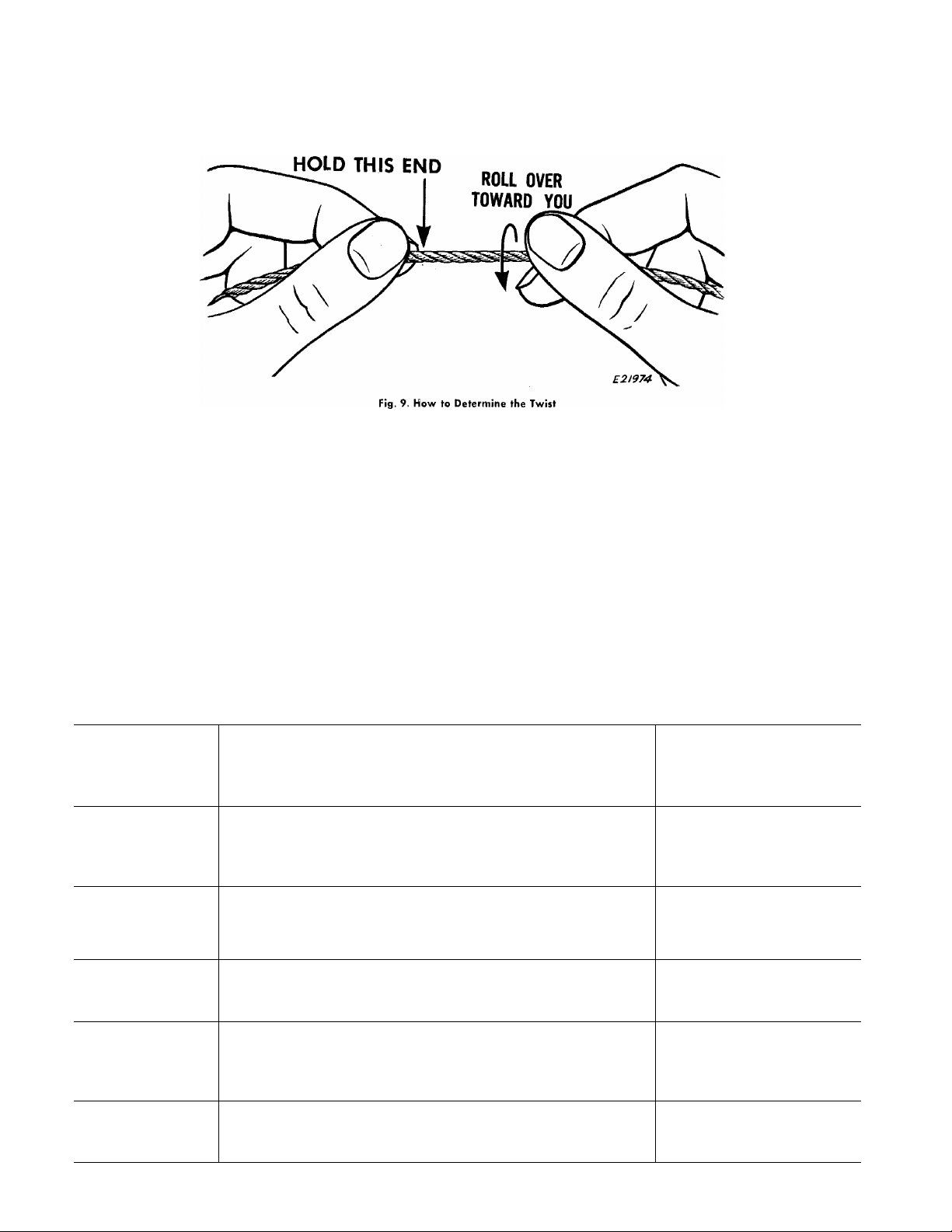
To determine the thread twist, hold the thread as
shown in Fig. 9. Then roll the thread over toward you—
if the strands of the thread wind tighter, the thread
is left twist; if the strands unwind or separate, the
thread is right twist.
RELATIVE SIZES OF NEEDLES AND THREAD
The following sizes of needles and thread are recommended according to the class of work:
SIZES
OF
NEEDLES
8 to Shirtings, Sheetings, Calicoes, Muslins, Silks, Dress
14
16
and
17
Goods and all classes of general work with light
and medium weight fabrics.
All kinds of heavy Calicoes, light Woolen Goods,
heavy Silk, Seaming, Stitching, etc.
CLASSES OF WORK
SIZES OF
COTTON, LINEN
OR SILK
60 to 80 Cotton
A and B Silk
40 to 60 Cotton
C Silk
18 Tickings, Upholstery, Woolen Goods, Trousers, Boys' 30 to 40 Cotton
Clothing, Cloaks, etc.
19
and
20 60 to 80 Linen
21 to
24 40 to 60 Linen
Heavy Woolens, Tickings, Bags, Heavy Coats,
Trousers, Heavy Clothing generally.
Bags, Coarse Cloths and Heavy Goods.
D Silk
20 to 30 Cotton
E Silk
1 6 to 20 Cotton
Page 10
10
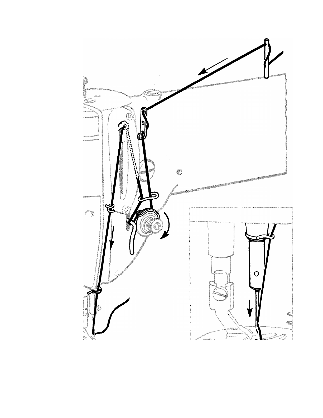
UPPER THREADING
Fig. 10. Upper Threading
First, turn the machine pulley over toward the oper
ator until needle is at Its highest point, then pass
the needle thread from the unwinder through the
Fig. 11. Threading the Needle
threading points in the order shown in Figs. 10 and 11.
Draw about two inches of thread through the eye
of the needle with which to start sewing.
Page 11
1. MOVE
TAKE-UP
TO HIGHEST
POINT
Fig. 12. Preparation
11
TO REMOVE THE BOBBIN
Turn machine pulley over toward operator,
until needle thread take-up lever is at highest
point, as shown in Fig. 12.
Reach beneath bed of machine with left
hand and remove bobbin, as instructed in
Figs. 13 and 14.
NOTE: While latch is kept open, bobbin will
be retained in bobbin case.
To remove bobbin from the bobbin case,
release latch and turn open end of bobbin case
downward. Bobbin will drop out, as shown
in Fig. 14.
2. OPEN
LATCH
3. HOLD LATCH
AND PULL CASE
FROM HOOK
Fig. 13. Removing Bobbin Case from Sevving Hook
4. RELEASE
LATCH \
5. BOBBIN 1
DROPS ▼
OUT
Fig. 14. Removing Bobbin
Page 12
12
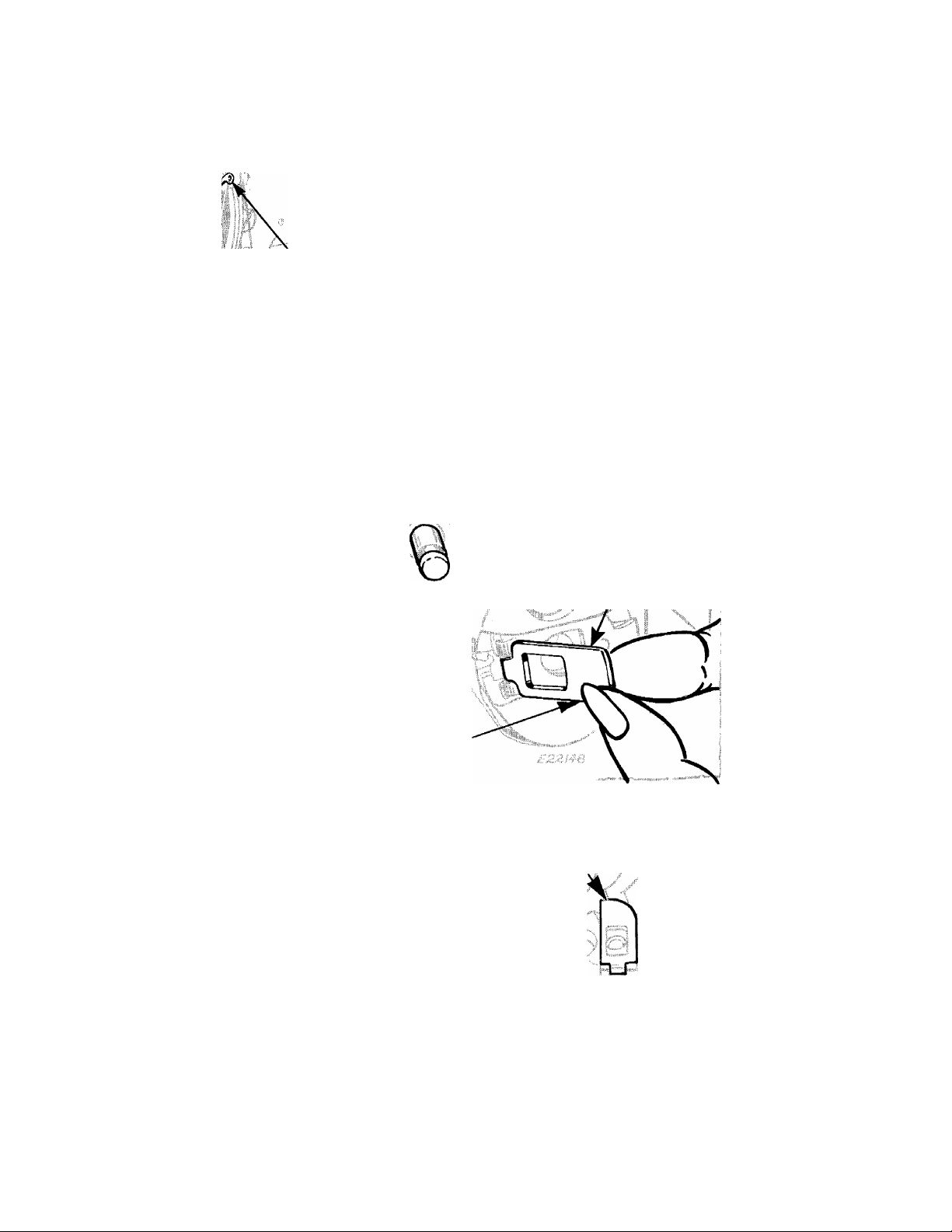
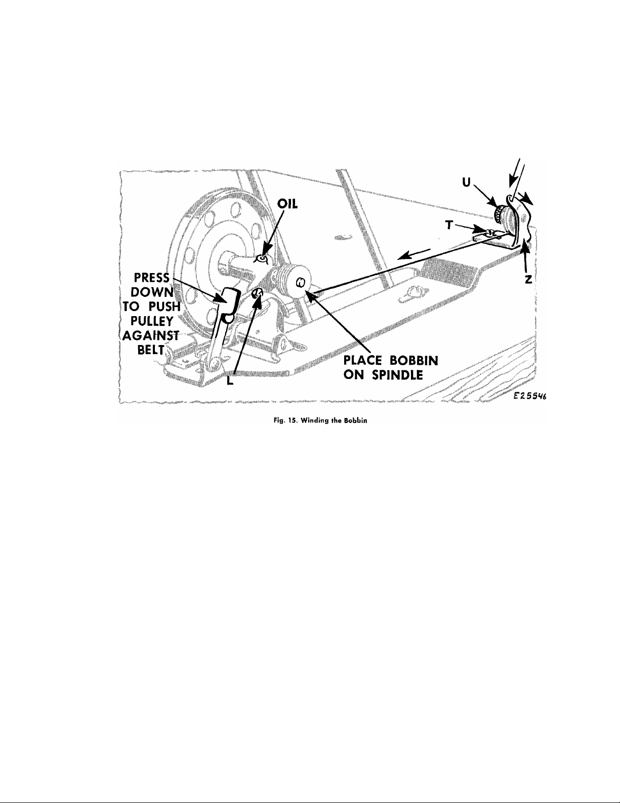
TO WIND THE BOBBIN
See Fig. 15
Fasten bobbin winder to table with its driving pulley
in front of the machine belt, as shown above, so that
bobbin winder driving pulley will make firm contact
with machine belt when thumb latch is pressed down
and pulley will be released from contact with belt
when sufficient thread has been wound upon the
bobbin.
Place bobbin on spindle, pushing it on as far as it
will go and pass thread through threading points, as
shown above.
Wind end of thread around the bobbin a few times.
Press down on thumb latch, pushing driving pulley
over against belt, as shown in Fig. 15. Start machine.
Bobbin winder will stop automatically, when the
amount of thread for which it is regulated is wound
upon the bobbin. For more thread on bobbin, turn
screw L inward; for less thread on bobbin, turn
screw L outward.
When winding a bobbin with fine thread, a light
tension should be used. Adjust the knurled nut
U, Fig. 15, to regulate the tension.
If thread winds unevenly on bobbin, loosen screw T
and move tension bracket Z to the left or right, as
required. Tighten screw T.
Bobbins can be wound while the machine is
stitching.
NOTE; Occasionally apply a few drops of oil to the
oil well, shown in Fig. 15, on top of the bobbin winder
frame.
Page 13
Hold the bobbin so that the thread will
unwind in the direction shown in Fig. 16.
13
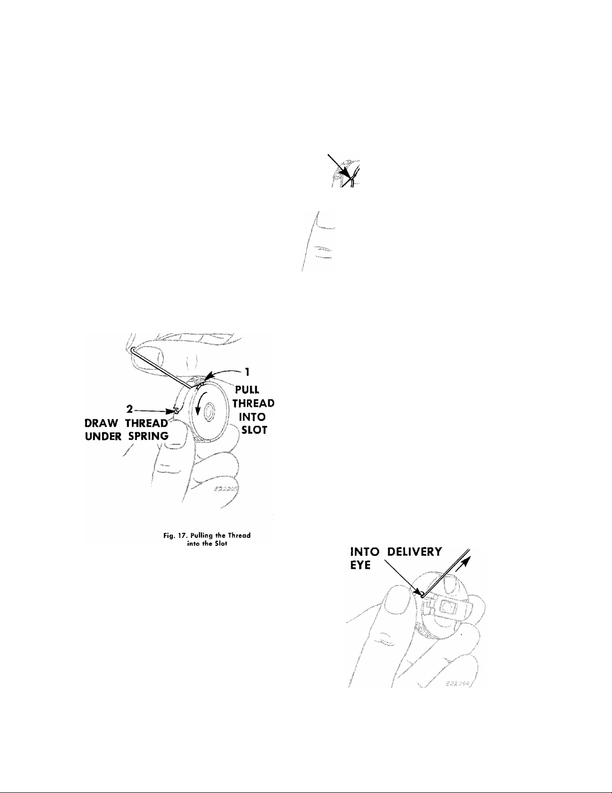
TO THREAD THE BOBBIN CASE
SLOT
NEAR
TOP
Hold the bobbin case as shown In Fig. 16
and place the bobbin into it.
/ \
I
Fig. 16. Placing Bobbin
in Bobbin Case
Pull the thread into the slot 1 and under
the tension spring 2, Fig. 17.
/
Draw the thread into the delivery eye at the
end of the tension spring, as shown in Fig. 18.
3. DRAW
THREAD
Fig. 18. Drawing the Thread
Under the Tension Spring
Page 14
14
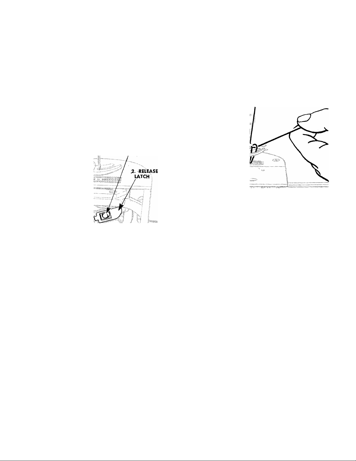
TO REPLACE THE BOBBIN CASE TO PREPARE FOR SEWING
1. REPLACE BOBBIN CASE
ON STUD
V
3. PRESS BACK
UNTIL LATCH CATCHES
GROOVE IN STUD
Fig. 19. Bobbin Case Threaded
and Replaced
After threading, take bobbin case by latch in the
left hand and place bobbin case on center stud of
bobbin case holder, as instructed in Fig. 19. Release
latch. Press bobbin case back until latch catches
groove near end of stud. Allow about two inches of
thread to hang free.
TO PREPARE FOR SEWING
Hold slack end of needle thread loosely and turn
machine pulley over toward you until needle moves
down and up again to its highest point, catching bob
bin thread. Draw up needle thread; bobbin thread
will come up with it through hole in throat plate, as
shown in Fig. 20. Lay both threads back under presser
foot.
Fig. 20. Drawing Up the Bobbin
Thread
TO START SEWING
Place material beneath the presser foot and start
to sew, turning the machine pulley over toward you.
TO REMOVE THE WORK
1. Let the thread take-up lever rest at its highest
point.
2. Raise the presser foot.
3. Draw the work toward the rear until it is clear
of the needle.
4. Cut the threads close to the goods.
Page 15

15
TENSIONS
EXPLANATION
For ordinary stitching, tension on needle and bobbin
threads should be balanced so that, if you cut straight
down through center of line of stitching and look at it
from the side, the line of stitching would appear with
needle and bobbin threads locked in center of thick
ness of material like this.
RIGHT
Fig. 21. Perfect Stitch
When there is too much tension on needle thread
or not enough on bobbin thread, needle thread can
not be pulled down into material, as required and
poor stitching results. The needle thread will lie on top
of material like this:
REGULATION
Needle Thread-
LESS
TENSION
Fig. 24. Regulating Needle
Thread Tension
First, regulate needle thread tension only when
presser foot is down.
Tension on needle thread should be ¡ust enough to
set stitch properly in material.
Having lowered presser foot, turn thumb nut at the
front of tension discs either over toward right or left,
as required. See instructions in Fig. 24.
Bobbin Thread—
WRONG
Fig. 22. Too Tight Needle Thread
Tension
When there is too much tension on bobbin thread
and not enough on needle thread, you get the reverse
of the condition shown in Fig. 22, above, but the
stitching is just as poor. The bobbin thread will lie on
bottom of material like this:
WRONG
Fig. 23. Too Loose Needle Thread
Tension
LESS
TENSION
Fig. 25. Regulating Bobbin
Thread Tension
When tension on bobbin thread has been properly
adjusted for ordinary stitching a correct stitch can
usually be obtained to suit the work in process by
varying tension on needle thread only.
For average sewing, tension on bobbin thread
should be very light.
To regulate tension on bobbin thread, remove the
bobbin case and turn screw in tension spring, as
instructed in Fig. 25.
Page 16

16
TO REGULATE THE LENGTH OF STITCH
CAUTION: DO NOT ATTEMPT TO CHANGE STITCH LENGTH WHILE MACHINE IS RUNNING.
2. TURN PULLEY
1 ;; ^ tP ;R, E S S
iPLUNGER
TOWARD YOU
SLOWLf
Fig. 26. Regulating Length of Stitch
To change the length of stitch, stop the machine-
then depress plunger, as instructed in Fig. 26, and turn
machine pulley slowly over toward you by hand until
plunger enters notch in eccentric (you will hear it click).
Then, still depressing plunger, turn machine pulley un
til number indicating the number of stitches per inch
you want is opposite mark on front of arm. Then
release plunger.
A setting of 17 stitches per inch is shown in Fig. 26
although you can set the machine to make as few as
5-1/2 stitches to the inch or as many as 30 (see chart
on page 4.)
Never depress the plunger while the machine is
running!
4. THEN fUiN
PULLEY TO DESIRED
STIfCM LiNGTM
TO PREVENT OPERATOR FROM
CHANGING STITCH LENGTH
The stitch regulator plunger (see 1 in Fig. 26) can
be removed to prevent an unauthorized person from
changing stitch length.
To remove the plunger, first remove the top cover.
Then remove the retaining ring near the tip of the
plunger, allowing the plunger to be withdrawn. The
hole in the top cover should then be filled by inserting
a plug screw 140607, which can be obtained at an
additional charge. Replace top cover.
Page 17

17
TO REGULATE THE PRESSURE ON THE MATERIAL
MORE
PRESSURE
L
------
J
LESS
PRESSURE
Fig. 27. Regulating the Pressure on the Material
The correct presser foot pressure helps feed the work
properly. You can regulate the amount of pressure by
means of the thumb screw, as shown in
The pressure on the material should be as light as
possible, while still sufficient to insure proper feeding.
NOTE:~The instructions on the following pages are for Service Representatives only.
Fig. 27.
To increase the pressure turn the thumb screw down
ward (clockwise). To reduce the pressure turn this
screw upward (counterclockwise). The pressure is
correct when the work moves steadily and smoothly
without stalling.
To insure proper timing and avoid unnecessary repetition these instructions should be followed in the order given.
Page 18

18
ТО SET THE NEEDLE BAR AT THE CORRECT HEIGHT
UPPER
TIMING
LOWEST POINT
в
NEEDLE BAR
AT
нк)!
I
м/с 25I-I
.484 inch
M/C25I-2
and 25I-3
.195 inch
UPPER
TIMING
MARK
NEEDLE BAR
vAT LOWEST
POINT
Fig. 28. Setting Needle Bar Height on Machines with Timing
Marks Aligned with UPPER Needle Bar Bushing
PREPARATION;
Remove face plate, slide plate and throat plate. See
that needle is correctly set in needle bar, as instructed
on page 8.
NOTE:
FOR MACHINES ON WHICH TIMING MARKS SHOULD
ALIGN WITH UPPER NEEDLE BAR BUSHING-
Top of bushing A, Fig. 28 must be flush with top of
casting, as shown in Fig. 28. To reset bushing, loosen
screw В and raise or lower bushing, as required.
FOR MACHINES ON WHICH TIMING MARKS SHOULD
ALIGN WITH LOWER NEEDLE BAR BUSHING-
Lower end of bushing K, Fig. 29 must be set as
shown in Fig. 29. To reset bushing, loosen screw L.
mmms
Fig. 29. Setting Needle Bar Height on Machines with Timing
Marks Aligned with LOWER Needle Bar Bushing
CHECK;
When needle bar is at its lowest point (during rota
tion of machine pulley), UPPER TIMING MARK on
needle bar should be level with lower end of bushing.
Check timing of hook as instructed on page 21.
SETTING:
Loosen clamping screw C, Figs. 28 and 29. Raise or
lower needle bar so that UPPER TIMING MARK is level
with lower end of bushing. Then securely tighten
screw C.
Replace throat plate and slide plate.
When replacing the face plate, make certain that
the screw holes in the face plate gasket are aligned
with the respective screw holes in the face plate;
avoiding injury to the gasket and consequent oil
leakage.
Page 19

19
TO SET CHECK SPRING
HEIGHT
PREPARATION:
Thread the machine.
CHECK:
HrOHER
Fig. 30. Setting Height of
Check Spring
TENSION
LOOSEN
\ /
H
/£;
Fig. 31. Adjusting Tension on
Check Spring
PREPARATION:
Thread the machine. Securely tighten set screw H,
Fig. 31. Make certain thumb nut is on stud J, Fig. 31.
Turn machine pulley over toward operator slowly.
When take-up lever begins to rise, check spring G,
Fig. 30 m akes a slight dip and a return to its higher
position. Later, as take-up lever approaches top of
stroke, check spring G should be drawn all the way
down; setting the stitch. As lever descends, check
spring G returns to rest.
SETTING;
Loosen screw H, Fig. 30. Turn stud J, Fig. 30 (at the
same time turning entire tension assembly) either over
toward left to lower check spring and decrease its
movement, or over toward right to raise check spring
and increase its movement. Securely tighten set screw
H.
NOTE:
Under certain conditions of tacking, it may be
necessary to set the check spring higher than it is
otherwise normally set.
CAUTION;
Check spring height setting must be checked each
time a different foot is applied to machine.
CHECK;
Tension on check spring G, Fig. 31, should be suffi
cient to ensure action at top speed; but still light
enough to permit itself to be drawn all the way down
(as take-up lever approaches height of stroke) before
any thread is drawn through the tension discs.
SETTING;
Using a large screwdriver in slot of stud J, turn
stud either over toward left to decrease tension or
over to right to increase it, as shown.
NOTE;
The tension on the check spring may require
different settings depending upon the size of thread
used. Heavier thread requires more tension to ensure
correct thread control.
Page 20

20
TO SET THE PRESSER BAR AT THE CORRECT HEIGHT
Fig. 32A. Required Clearance on Machines
with Latest Type Lifting Bracket
RESTING
FIRMLY
UPON
THROAT
PLATE
E27555
Fig. 32. Checking Height of
Presser Bar
PREPARATION:
Remove face plate and slide plate.
CHECK:
1. When presser foot rests firmly upon throat plate
(with feed dog below throat plate) there should
still be some clearance between guide bracket
D, Figs. 32 and 32A and lifting bracket E, as shown
in Figs 32 and 32A.
. AT
AT A
HIGHEST
POINT Î
LOWEST
PbiNT
JUST
CLEAR
E27SSÔ
Fig. 33. Setting Presser Bar
at Correct Height
SETTING:
Loosen clamping screw F, Figs. 32 and 32A. Raise
or lower guide bracket D, as required. Securely tighten
screw F.
CAUTION:
2. When presser foot is at its highest point and needle
bar is at its lowest, top of presser foot should
clear lower end of needle bar, as shown in Fig. 33.
Whenever guide bracket has been moved on presser
bar, inspect the check spring for correct setting, as
instructed on
page 19.
Page 21

21
TO TIME THE SEWING HOOK
LOWER
TIMING
MARK
LOWER
TIMING
MARK
ON
UPWARD
STROKE
Fig. 34A. Checking the Tinning of the Hook
on Machines with Tinning Marks at
Lower End of Needle Bar
I ON
UPWARD
STROKE
H
'IL
E27559
Fig. 34. Checking the Timing
of the Hook
(Viewed fronn Front)
PREPARATION:
Remove presser foot, slide plate, throat plate and
feed dog.
Remove face plate on machines on which timing
marks are on upper half of needle bar.
CHECK:
ON MACHINES ON WHICH TIMING MARKS ARE
ON UPPER HALF OF NEEDLE BAR-
When lower timing mark on needle bar is level with
lower end of upper needle bar bushing A as shown
in Fig. 34, the point of the sewing hook should be at
the center of the needle, as shown in enlarged view
in Fig. 35.
HOOK POINT
AT CENTER
OF NEEDLE
Fig. 35. Timing the Hook
(Viewed from Rear)
ON MACHINES ON WHICH TIMING MARKS ARE
ON LOWER HALF OF NEEDLE BAR-
When lower timing mark on needle bar is level
with lower end of lower needle bar bushing K as
shown in Fig. 34A, the point of the sewing hook
should be at the center of the needle, as shown in
Fig. 35.
TIMING:
Loosen two set screws L, Fig. 35 in hub of hook.
Turn hook on its shaft, as required to bring point of
hook to center of needle, as shown above.
Make certain that hub of hook is against oil-re
taining collar; then securely tighten screws L.
Page 22

...cl
'"-/ ^ " •■ .■ •
É
f®
22
TO SET THE SEWING HOOK SIDEWISE
IN RELATION TO THE NEEDLE
m:
POINT
|S3Sff
FLAT OF ,/
HOOK POINT
I'WKlEP GEARS
IN ME!
Fig. 36. Hook Point
Passing thè Needle
Fig. 37. Flat of Hook
Point Clearing the
Needle Scarf
PREPARATION;
Remove slide plate, throat plate and bobbin còse.
Seat needle correctly in needle bar, as instructed on
page 8. Time the sewing hook as instructed on page 21.
CHECK;
When point of sewing hook passes needle, clearance
between hook point M, Fig. 36 and needle should be
approximately equal to thickness of a piece of ordinary
notepaper (about .005 inch), as shown in Fig. 37.
NOTE;
Not only point of sewing hook but entire ''FLAT" of
hook point should clear scarf on needle blade.
SETTING:
Loosen screws #1 and #2 in hub of hook shaft
bevel gear P, Fig. 38.
Fig. 38. Preparation
for Setting:
Loosening Bevel Gear
CAUTION:
MAKE CERTAIN THAT THE TWO BEVEL GEARS ARE
KEPT IN MESH UNTIL SET SCREWS #1 AND #2 ARE
SECURELY RETIGHTENED.
Using a light mallet and a 1/4 inch brass drift pin,
as shown in Figs. 39 an d 40, move hook assembly
either toward or away from needle, as required.
TAP VERY LIGHTLY on drift pin to avoid injury to
hook assembly.
Securely tighten screw N, Fig. 40.
Remove all end shake from hook shaft by pushing
the hook assembly firmly against front hook shaft
bushing and, at the same time, pushing hook shaft
bevel gear P, Fig. 38 toward the hook on the shaft.
Then securely tighten screw #1, Fig. 38; then screw #2.
Loosen hook shaft bushing set screw N, Fig. 40,
page 23.
Replace bobbin case, throat plate and slide plate.
Page 23

23
m
I
loosen r DAMAGE
SET SCREW ^
III
ri-
DO NOT
HIT BRIDGE
BRASS DRIFT PIN
F'g. 39. Moving Sewing Hook Assembly
TAP
lightly
Toward the Needle
loosen
SET SCREW
N
.. ,1 M
V
f
TAP
lightly
?
/
'/4" BRASS DRIFT PIN
1
K0. IO. Mov,„3 sowing Hook Assembly A»„y
■
from the Needle
Page 24

24
TO TIME THE FEED
Before the machine leaves the factory, the feed
lifting eccentric-and-bevel-gear and the feed eccentric
are both set for average sewing conditions; having the
timing screw in each eccentric enter groove provided
for it in the arm shaft.
As the grooves in the arm shaft are not visible to
the adjuster, the machine pulley should be turned over
toward operator until feed lifting eccentric connecting
rod A2, Fig. 41 is at its lowest position. Timing screw Y,
Fig. 41 will then be on top of feed lifting eccentric-and-
bevel-gear. Loosen timing screw Y and set screw O
and, while maintaining this position of the gear, turn
arm shaft until timing screw, as it is slowly tightened,
can be felt to drop into its groove in arm shaft. Se
curely tighten timing screw Y and set screw O.
Feed eccentric timing screw Z, Fig. 41 appears im
mediately after large stop screw W, Fig. 41, when
feed eccentric is rotated over toward operator.
Feed eccentric should be set for average sewing
conditions, by having this timing screw Z exactly in
line with timing screw Y, as shown in Fig. 41. Thus,
as timing screw Z is tightened it will drop into its
groove in arm shaft which is in line with groove pro
vided for feed lifting eccentric-and-bevel-gear timing
screw Y. Securely tighten timing screw Z and the two
set screws in feed eccentric.
If for any reason, it is necessary to alter the timing
of either eccentric, timing screw should be removed
and eccentric locked in desired setting by means of
set screws only.
NOTE: Whenever the timing of the feed is changed,
sewing hook should be checked for necessary adjust
ment also, as instructed on page 21.
Page 25

TO SET THE FEED DOG AT THE CORRECT HEIGHT
FULL DEPTH REAR TEETH
nnnn
25
T
Fig. 42. Showing Feed Dog at Correct Height
When the feed dog is at Its highest position^ ap
proximately the full depth of the rear teeth of the feed
dog should project above the top surface of the
throat plate, as shoyvn in Fig. 42.
Before checking the height of the feed dog, set the
machine for the longest stitch, as instructed on page 16.
To adjust, loosen the clamping screw B2, Fig. 43
and raise or lower the feed dog (which is fastened
to the feed bar C2, Fig. 43) as required. Then securely
tighten screw B2.
THROAT PLATE
B2
THE FEED DOG ECCENTRIC STOP SCREW
The machine is prevented from making longer
stitches than a predetermined maximum by the Stop
Screw W, Fig. 44 in the feed eccentric.
Feed eccentric stop screw 140256, furnished with
Machine 251-1, permits a maximum length of seven
stitches per inch.
Stop screw 140258, for 14 stitches per inch or
shorter, can also be used.
Machines 251-2 and 251-3 are regularly fitted with
stop screw 140257 permitting a maximum length of
5-1/2 stitches per inch, but either 140256 (7 stitches
per inch) or 140258 (14 stitches per inch) can be used.
Fig. 43. Adjusting
Height of Feed Dog
Page 26

Page 27

27
INSTRUCTIONS
FOR
REMOVAL AND REPLACEMENT
OF
PRINCIPAL ASSEMBLIES
CAUTION TO MECHANICS
Machines of Class 251- are made with extreme precision in machining and
assembly, and the "Superfinish" process provides microscopically smooth bearing
surfaces. Therefore, special care should be taken not to permit any misalignment
of parts or to cause any scratches or nicks on the bearing surfaces by careless
assembly or handling of parts. Any such damage might render the machine
incapable of the long, trouble-free service for which it is designed.
Page 28

28
TO REMOVE THE SEWING HOOK
143350
Fig. 45. Removing Sewing Hook
Remove the needle, slide plate, throat plate and
bobbin case. Remove the screw D2, Fig. 45 and the
bobbin case holder position bracket E2, Fig. 45. Loosen
the two set screws X, Fig. 45 in the hub of the hook
and turn the machine pulley over toward the oper
ator until the feed bar C2 is raised to its highest point.
Turn the sewing hook until the thread guard F2, is
at the bottom, as shown in Fig. 46. Turn the bobbin
case holder G2, Fig. 46 until the notch J2 is also near
S2ZH2
F2
Fig. 46. Replacing Oil Filter
the bottom, as shown in Figs. 46 and 47. The sewing
hook can then be removed from the hook shaft.
TO REPLACE OIL FILTER 143350
While the sewing hook is off the shaft, it is advis
able to replace the oil filter 143350, Fig. 46, in the
end of the hook shaft. Unscrew the filter from the
center of the shaft at H2, Fig. 46 and replace with cl
complete new filter 143350.
Page 29

29
TO REPLACE THE SEWING HOOK
J2
E2
Fig. 47. Replacing Sewing Hook (Correct Position of Thread Guard
and Bobbin Case Holder)
When placing a new sewing hook on the shaft,
have the sewing hook thread guard F2 at the bottom
and the bobbin case holder G2 turned to the position
shown in Fig. 47, so that the hook will clear the feed
bar C2.
Place the hook in position on the shaft and turn the
bobbin case holder G2 until the notch J2 is at the top,
as shown in circular inset above. Replace the bobbin
case holder position bracket E2, making certain that
the finger K2 (see inset) enters the notch J2 at the top
of the bobbin case holder. Then securely fasten the
position finger by means of the screw D2.
Replace the needle. Time the sewing hook, as in
structed on page 21. Replace the bobbin case, throat
plate and slide plate.
Page 30

30
TO REMOVE AND REPLACE THE HOOK SHAFT
HOLD GEARS IN MESH
Fig. 48. Removing and Replacing Hook Shaft
Remove and replace the hook shaft in the follow
ing manner:—
1. Remove the sewing hook, as instructed on
page 28.
2. Mark the two lower bevel gears L2 and S4,
Fig. 48, with chalk or crayon, on one tooth of one
gear and the corresponding space for that tooth
in the other gear. This is important, as these gears
may become separated during removal of shaft.
These marks will then make it possible to obtain
the original mating position of the gears.
3. Loosen the two set screws #1 and #2 in hook
shaft bevel gear. While holding the two gears
L2 and S4 in mesh, as instructed in Fig. 48, with,
draw the old hook shaft and INSERT THE NEW
SHAFT.
NOTE: Set screw #1 is the first of the two set screws
to appear on the hub of the bevel gear S4 as the
machine pulley is turned over toward operator.
4. Replace the sewing hook, as instructed on
page 29.
Make certain that set screw #T seats over flat
on the hook shaft. Remove all end shake from
hook shaft, by pushing hook firmly against front
hook shaft bushing and, at the same time, push
ing gear S4, Fig. 48 toward the hook on the
shaft. Securely tighten first set screw #1, then
securely tighten the second screw #2.
6. Time the sewing hook as instructed on page 21.
Page 31

31
THE OIL PUMP
TO REMOVE
1. Loosen the two oil pipe clamping sleeve nuts 52,
Fig. 49.
2. Remove the four screws N2, Fig. 48.
3. Remove the screen frame, screen and oil pump
cover 02, Fig. 48.
4. Remove the locking screw 02, Fig. 49.
5. Remove the impeller P2, by turning it over toward
the RIGHT (clockwise) to loosen it, as instructed
in Fig. 49.
CAUTION:—The impeller P2 is designed to be screwed
to the shaft by means of a LEFT-HAND THREAD and
must be turned over toward the right to be loosened.
Avoid damage to this impeller, as the efficient auto
matic lubrication of the machine is dependent upon it.
6. Remove the three screws T2.
TO REPLACE
1. Place oil pump body on underside of ma
chine bed, so that position pins V2, slip into
proper holes in machine casting, as shown above.
2. Replace and securely tighten the three screws T2.
Make certain that machine turns freely as screws
are tightened.
3. Carefully replace impeller P2, turning it over
toward the LEFT to screw it on arm shaft (see
CAUTION at left).
4. Make certain that impeller P2 is not so tight that
it will bind arm shaft. Make certain also that im
peller clears both top and bottom of interior of
oil pump body, then lock it in position by means
of locking screw Q2.
5. Replace pump cover, screen and frame 02 and
four screws N2, Fig. 48. Securely tighten
screws N2.
7. Carefully pull the oil pump body off the lower
end of the upright arm shaft.
6. Replace two oil pipes in oil pump body, as shown
above, and securely tighten sleeve nuts 52.
Page 32

TO REMOVE AND REPLACE THE UPRIGHT ARM SHAFT
(See Fig. 50)
REMOVAL;
If it is found necessary to remove the upright arm
shaft K3, it should be removed in the following
manner;—
1. Remove oil pump, as instructed on page 31.
2. Follow the instructions in Steps 2 and 3 for re
moval of hook shaft on page 30 except that. In
stead of removing hook shaft, merely remove
hook shaft bevel gear S4, Fig. 48.
3. Remove arm top cover.
32
4. Remove screw L3 and oil lead M3.
5. Remove four cap screws N3.
6. Remove oil flow window cap 03, window P3,
oil flow body R3 with two gaskets Q3.
7. Mark the two bevel gears S3, with chalk or cray
on, on one tooth of one gear and the correspond
ing space between the teeth of the other gear so
that these gears may be re-assembled in their
original relative positions without difficulty, if
necessary.
8. Loosen set screws T3 in bevel gear at upper end
of upright arm shaft.
9. Make certain bevel gear at lower end of upright
arm shaft is fastened securely. Then while hold
ing upper bevel gears S3 in mesh, draw upright
arm shaft down and out of machine.
03 R3 03 P3
Fig. 50, Removing Upright Arm Shaft
2. Insert upright arm shaft up through upper bevel
gear, as shown in Fig. 50.
3. Turn shaft so that one of the two set screws T3
will bear upon the upper gear flat on the shaft
and tighten the set screws T3.
4. Replace and set hook shaft bevel gear as in
structed in Step 5 on page 30.
REPLACEMENT;
1. Before installing upright arm shaft, make certain
it has the bevel gear L2, Fig. 48 correctly fastened
at the lower end of shaft.
5. Replace oil pump, as instructed on page 31.
6. Replace oil flow window assembly, in the order
shown in Fig. 50.
7. Replace oil lead M3 and arm top cover.
Page 33

33
TO REMOVE AND REPLACE THE NEEDLE BAR
(See Fig. 51)
Remove the needle bar in the following manner:—
1. Remove needle and needle set screw (or needle
clamp).
2. Remove face plate.
3. Loosen clamping screw M.
4. Loosen screw R2 sufficiently to allow needle bar
to pass, then slip needle bar up through both
needle bar bushings and out of machine.
NOTE: If it becomes necessary to remove upper needle
bar bushing N, first remove screw R2 and take-up lever
oil guard W2. Then loosen set screw P and drive
bushing N down and out of head of machine. Use a
13/32 Inch driving pin.
Fig. 51. Removing and Replacing
Needle Bar and Presser Bar
TO REMOVE AND REPLACE THE PRESSER BAR
To remove the presser bar:-
Remove presser foot and face plate.
1.
Remove presser bar pressure regulating thumb
2.
screw, X2, w ith pressure bar guide from head
of the machine.
3. Loosen clamping screw V about one turn (just
enough to make it loose). Loosen screw A5 and
slip guide bracket T up off presser bar and out
of machine.
4. Slide presser bar up through lifting bracket U,
Fig. 51 and bushing and out of machine.
Before replacing needle bar, replace upper needle
bar bushing N, by driving it down into hole provided
for it in head of the machine. Make certain top of
bushing N is level with top of arm. Tighten set screw P.
Replace needle bar in the following manner*.—
1. Slip needle bar down through both bushings in
head of the machine. Tighten screw M.
2. Replace needle clamp and needle. See page 8.
3. Set needle bar at correct height and replace face
plate, as instructed in last paragraph on page 18.
4. Replace oil guard W2 and fasten it securely to
bushing with set screw R2.
To replace the presser bar:—
1. Slip presser bar down through lifting bracket U,
Fig. 51 and lower presser bar bushing.
2. Replace guide bracket T as shown in Fig. 51.
3. Replace presser foot.
4. Replace presser bar pressure regulating thumb
screw X2 with presser bar guide.
5. Set the presser bar at the correct height, as in
structed on page 20.
6. Tighten screw V.
7. Tighten screw A5; making sure that slack thread
regulator B5 just clears the casting. Replace face
plate, as instructed on page 18.
Page 34

34
TO REMOVE THE NEEDLE THREAD TAKE-UP
H3
DO NOT
DISTURB
DO NOT
DISTURB U2
Fig. 52. Removing Needle Thread Take-up Fig. 53. Needle Bar Crank
Remove needle thread take-up in the following man
ner:—
1. Remove face plate and arm hole plug A3, Fig. 53
from machine.
2. Remove needle bar, upper needle bar bushing,
presser bar pressure regulating thumb screw X2,
Fig. 51, page 33, and guide bracket T, Fig. 52 as
instructed on page 35.
3. Turn machine pulley as required to reach screw
Y2, Fig. 53, in needle bar crank through hole left
by removal of plug A3. Loosen set screw Y2.
4. Using wrench 146057 (through same hole) and
turning machine pulley as required, loosen the
large hexagon head clamping screw Z2, Fig. 53,
on needle bar crank.
CAUTION: DO NOT DISTURB the smaller hexagon head
position screw U2, Fig. 53, which holds the needle bar
crank at its correct position on the horizontal arm shaft.
5. Loosen small set screw B3, Fig. 52 in the rear of
the arm of the machine.
6. Insert a face plate screw E3, Fig. 52.in the tapped
hole in center of stud C3, Fig. 52 and, while hold
ing back the needle thread take-up link inside
the head at G3, Fig. 52, pull upon the screw E3
until the stud C3 is removed. Remove face plate
screw from stud.
NOTE: Extractor Tool Serial 222226 may be used in
stead of face plate screw at E3, Fig. 52, to pull hinge
stud C3.
7. Back the end of the take-up H3, Fig. 52 toward
the inside of the machine, turning the machine
pulley as required until the take-up is free of the
slot provided for it.
8. The needle thread take-up link assembly (includ
ing parts F3, G3, H3, J3, Z3 and W4) can now be
pulled free of the needle bar crank WITHOUT
DISTURBING THE NEEDLE BEARINGS WITHIN THE
THREAD TAKE-UP CRANK AT F3, Fig. 53.
NOTE: If the needle bearings at F3, Fig, 53, are acci
dentally disturbed, they must be reassembled so that
there are exactly 18 bearings in each of the two as
semblies.
Page 35

TO REPLACE THE NEEDLE THREAD TAKE-UP
Replace the needle thread take-up in the following manner:
35
1. Make sure that the wearing plate J3 is in place
and undamaged on the face of the needle bar
crank, as shown in Fig. 52.
2. Place the needle thread take-up link G3 and takeup H3 in the head of the machine so that the stud
W4, Fig. 52 in the center of the linkage slips into
the hole provided for it in the needle bar crank,
as shown in Fig. 52.
3. Slip the upper end of the take-up H3 through the
slot provided for it in the head of the machine.
4. Insert stud C3 through needle thread take-up
lever link G3 and into its hole into the machine
casting so that the flat on the stud faces the rear
of the machine. The mark D3 on the stud indicates
the position of this fiat. Fig. 52 shows the stud
with the mark D3 in the correct position. DO NOT
INSERT THE STUD TO ITS FULL DEPTH AT THIS
TIME. There should be about .010 inch to .015
inch side play of the take-up lever link G3 on the
stud, until final adjustment is made in Step 15.
5. Turn the set screw B3 inward lightly against the
flat on the stud C3. DO NOT TIGHTEN screw БЗ
until final adjustment is made in Step 15.
6. Turn machine pulley as required to make set
screw Y2 in needle bar crank accessible through
hole at A3, Fig. 53 in front of machine head.
7. Insert a screwdriver through this hole and, while
turning stud W4 by hand to find its flat, turn set
screw Y2 until it bears tightly upon the flat.
8. Turn screw Y2 back, just enough to "break It
loose."
play by pushing take-up lever H3 gently right
and left; there should be .001 to .002 inch side
shake between lever and wearing plate.
10. Move thread take-up crank inward or outward
in needle bar crank, as required, to obtain clear
ance.
11. Using wrench 146057, through same hole and
turning machine pulley as required, tighten hexa
gon head screw Z2 lightly.
12. Loosen set screw Y2.
13. Securely tighten clamping screw Z2.
14. Securely tighten set screw Y2.
15. Push hinge stud C3 fully into machine casting and
securely tighten set screw B3.
16. Turn machine pulley slowly, by hand, at least
one complete revolution; testing take-up for bind
ing, end shake and noise. If binding occurs, re
check clearance between take-up and wearing
plate J3 and between hinge stud C3 and machine,
casting.
17. Replace guide bracket T in head of machine, as
shown in Fig. 52.
18. Replace presser bar pressure regulating thumb
screw X2, Fig. 51, page 33.
19. Replace and adjust upper needle bar bushing and
needle bar with their accessories, as instructed on
pages 18 and 33.
20. Replace and securely tighten arm hole plug A3.
9. Make certain that assembly F3 is firmly against,
but does not bind, wearing plate J3. Test for side
21. Replace the face plate (see instructions at bottom
of page 18).
Page 36

TO REMOVE AND REPLACE ARM SIDE SHIELD WICK, NEEDLE BAR WICK
AND NEEDLE BAR CONNECTING STUD WICK
(See Fig. 54)
Arm side shield wick may be remdved, after re
moving face plate and two screws U3. Lift arm side
shield V3 up and out of machine.
When replacing arm side shield wick, make sure
that lower end of wick drops into oil pool beneath
needle bar crank and that the two upper wick loops
are located as close as possible to the needle bearings
at F3, Fig. 55 without touching them. Then replace and
securely tighten screws U3.
To remove needle bar wick and connecting stud
wick, move take-up lever H3, so that it does not inter
fere with removal of oil guard W2. Then remove face
plate and screw R2; lift take-up oil guard W2, with
the two wicks, up and out of machine.
36
When replacing the oil guard W2, which carries
the needle bar wick and connecting stud wick, make
sure that lower end of the stud wick drops into oil
pool behind lower needle bar bushing and that the
loop of needle bar wick is placed behind the needle
bar, as shown in Fig. 54.
TO REMOVE OIL WICK HOLDER
(See Fig. 55)
Oil wick holder includes two oil wick leaders (see
Fig. 56) and an oil wick for the needle bar link and for
the two sets of needle bearings in the thread take-up
as shown in Fig. 55. It is removed in the following
manner:—
Remove face plate, needle bar and upper needle
bar bushing from the machine, as instructed on
page 33.
Fig. 54. Arm Side Shield Wick,
Needle Bcir Wick and Connecting
Stud Wick
2. Remove upper section
structed on page 33.
3. Remove holder screw W3.
Pulling gently, draw entire oil wick holder as
sembly out of the head of the machine.
of presser bar, as in-
Fig. 55. Wick Loops for Needle
Bar Link and Thread Take-up
Page 37

37
TO INSTALL NEW OIL WICK HOLDER
WICK
NOT REACHING
Fig. 56. Replacing Oil Wick Holder
(Correct Installation)
1. Remove old oil wick holder os instructed at bot
tom of page 36.
2. Remove top arm plug Y3, Fig. 56. (Use a sharpbladed screwdriver or a small chisel to pry plug
Y3 from arm casting.)
3. Insert two oil wick leaders into arm casting, as
shown in Fig. 56, so that wick is slack over edge
Fig. 57. Incorrect
of casting at point A4, Fig. 56. This will insure
free passage of oil. Use tweezers through the
plug hole at Y3 to loop the wick and bring it
into positive contact with the arm shaft approxi
mately at the point B4 shown in Fig. 56.
Installation
pushed all the way down into the smaller hole,
without jatntning, until they touch the arm shaft, as
shown in Fig. 56.
4. When oil wick leaders are correctly installed, re
place holder screw W3, Fig. 56.
5. Adjust the three oil wick loops in holder (see
Fig. 58. Incorrect
Installation
Figs. 55 and 56), so that two of the loops come
as close as possible to, without touching, the
two sets of needle bearings F3 while the third
wick loop makes positive contact with the wick
inside the stud C3, in the needle bar link, as
shown in Fig. 55.
NOTE: DO NOT FORCE the wick leaders down too
tightly against the edge A4 of the casting, as shown
in Fig. 57, as this will decrease the flow of oil from
the arm shaft to the needle bar link and take-up
bearings.
CAUTION: If the bottom of either oil wick leader is
caught on the ledge as shown at C4, Fig. 58, no oil
can be taken up by the wick to be carried to the
needle bar link and thread take-up bearing, where
it is needed. Make sure that the oil wick leaders are
6. Securely tighten holder screw W3.
7. Replace arm top plug Y3.
Replace upper section of presser bar, upper
needle bar bushing and needle bar, as instructed
on page 33.
9. Replace face plate, as instructed in last para
graph on page 18.
Page 38

38
OIL-REMOVING WICK ASSEMBLY (HEAD END) COMPLETE T 47056
lr%
\
Fig. 59. Preparing to Remove
Oil-Removing Wick
Fig. 60. Removing Oil-Removing
Wick Assembly 147056
DESCRIPTION
Oil-removing wick assembly. Complete 147056, shown in Fig. 61 is designed to remove excess oil from the
head of the machine arm.
When filling the machine reservoir, use "TYPE A" or "TYPE C" OIL, sold by Singer Sewing Machine Company.
If inferior oil is used, absorption of the excess oil by this wick may be reduced considerably. The consequent
leakage of accumulated oil will then cause serious damage to materials being sewn. For further instructions on
oiling, see inside front cover of this book and pages 2, 6, 7 and 31.
Additional sets of the oil-removing wick, wick holder body and spring, as shown in Fig. 61, will be furnished
on order.
PREPARATION FOR REMOVAL-
(See Fig. 59)
1.
Remove face plate.
Loosen presser foot lifting lever hinge screw E4,
2.
and presser foot lifting lever link stud screw F4.
Remove head end of presser foot lifting lever G4
3.
with spring H4, from the machine arm.
Remove presser foot screw and presser foot and
4.
presser bar thumb screw X2, with upper section
of presser bar.
Remove arm side shield with wick, as instructed
5.
on page 36.
Loosen screw V and remove guide bracket T, as
6.
instructed on page 33.
Remove presser bar lifting link J4, with stud.
7.
Loosen four screws K4, in the oil removing hinge
8.
plate and cover L4.
REMOVAL-
(See Fig. 60)
1. Turn machine pulley over toward the operator,
until the needle bar crank is in the position
shown at M4.
2. Lift wick LOOP up and off lower presser bar
bushing and lift wick END out of oil pool behind
needle bar bushing, as shown In Fig. 60.
3. Simultaneously push upward against wick and
wick holder at N4, while pulling outward gently
on hinge plate and cover L4, as shown in Fig. 60,
removing hinge plate and cover with oil-remov-i
ing wick and holder body from the machine.
Page 39

39
OIL-REMOVING WICK ASSEMBLY (continued)
RELEASE SPRING
SLIP SPRING
Fig. 61. Disassembly of Oil
Removing Wick
(Showing Oil-Removing Wick)
Wick Holder Body and Spring
147108)
DISASSEMBLY-
1. Release end of spring from catch on the holder
body 04, as instructed in Fig. 61.
2. Remove hinge screw, as instructed in Fig. 61.
3. Oil-removing wick and holder N4 may then be
removed from hinge plate and cover L4, as
shown in Fig. 61.
CAUTION: Before inserting a new oil removing wick,
it must be saturated with oil.
Removing Wick (with Holder)
in Assembly 147056
ASSEMBLY-
(See Fig. 62)
1. Insert open end of holder body 04, (with new
Wick) into hinge plate and cover L4.
2. Replace and securely tighten hinge screw as in
structed in Fig. 62.
3. Slip end of spring into catch on holder body 04,
as instructed in Fig. 62.
4. Place gasket P4 on hinge plate and cover L4.
5. Align the screw holes in the gasket P4 with the
screw holes in the cover L4 and insert the four
screws K4, Fig. 66, page 41 through cover and
gasket to hold the gasket in place.
Page 40

OIL-REMOVING WICK ASSEMBLY (continued)
«
¥§ I Hi
\ ^ ‘.i- ®E'-'''5.’ Ji;
40
SLIDE
INTO
RECESS
PULL
WICK
Ip
' ‘
Bf f
iiii i
‘'X
Fig. 63. Replacing Oil-Removing
Wick and Holder in Head of Machine
REPLACEMENT-
1. Turn machine pulley over toward operator until
the needle bar crank is in the position shown at
M4, Fig. 63.
2. Fold oil-removing wick along the side of the
holder body, as shown in Fig. 63 and insert oilremovimg wick, holder and hinge plate into
head of machine.
Fig. 64. Pulling Wick into
Machine
3. Place index fìnger under wick and holder body
and simultaneously pull the oil-removing wick,
as required, sliding the hinge plate and cover L4
fully Into its recess in the head of the machine,
as shown in Fig. 64.
4. Securely tighten the four screws K4, Fig. 63.
5. Check the entire assembly to make certain that
the holder body (see 04, Figs 61 and 62) hinges
freely under the needle bar crank.
Page 41

41
OIL-REMOVING WICK ASSEMBLY (continued)
if
Ml
m
III
I
IB
il
1 .«w»« J
Fig. 65. Location of Wick
Loop and Wick End
in Machine Head
LOCATION OF WICKS-
1. Replace END of wick behind tension releasing
lever Q4 and into oil pool behind lower needle
bar bushing, os shown in Fig. 65.
2. Replace LOOP behind and then under tension re
leasing lever Q4 and out over lower presser bar
bushing, as shown in Fig. 65.
REPLACEMENT OF OTHER PARTS
1. Replace presser bar lifting link J4, Fig. 66 with
stud.
'smi
'
N-
Fig. 66. Replacement of Other
Parts in Head of Machine
3. Replace arm side shield with wick, as instructed
on page 36.
4. Replace upper half of presser bar and presser
bar thumb screw X2, Fig. 66.
5. Replace presser foot and presser foot screw.
6. Place presser foot lifting lever G4, Fig. 66 with
spring H4 on machine arm and fasten lever to
arm with hinge screw stud E4, Fig. 66.
7. Tighten screw F4, Fig. 58.
2. Replace guide bracket T, Fig. 66. (See page 33,
also.) Tighten screw V, Fig. 66.
8. Replace face plate as instructed on page 18.
Page 42

42
THE ARM SHAFT
T4
Fig. 67. Loosening the Feed Eccentric
REMOVAL-
(See Figs. 67 to 69)
1. Remove the face plate.
2. Remove the arm side shield and wick and the
thread take-up oil guard, as instructed on
page 36.
3. Remove the needle bar, upper needle bar bush
ing, presser foot and presser bar, as instructed on
page 33.
4. Remove entire thread take-up lever assembly, as
instructed on page 34.
7. Loosen the four screws in the arm top cover and
remove the arm top cover.
8. Remove the oil lead that is fastened to the casting
just beneath the arm top cover.
9. Remove the feed timing screw Y, Fig. 67 and
loosen the set screw O, Fig. 67, in the feed-liftingeccentric-and-bevel-gear, X3, Fig. 67.
10. Remove the timing screw Z and loosen set screws
in the feed eccentric U4, Fig. 67.
11. Remove arm shaft screw R4, Fig, 67 from ma
chine pulley end of arm shaft.
5. Remove the oil-removing wick, as instructed on
pages 38 and 39.
6. Set the machine at any stitch length except the
longest or the shortest (see instructions on
page 16) to prevent binding of the arm shaft
during removal and replacement.
12. Loosen the two set screws T4, Fig. 67 and remove
the machine pulley.
13. Turn the needle bar crank until it is in the position
shown at M4, Fig. 69, to prevent crank from dis
turbing the three wick loops in holder W4, Fig. 69
during removal of arm shaft.
Page 43

43
THE ARM SHAFT (continued)
Z4
X4
i
Fig. 68. Removing the Arm Shaft
REMOVAL (Continued)
CAUTION: The feed-timing-bevel-gears at S3, Fig. 68
have been lapped together at the factory and should
be kept in mesh (as instructed in Fig. 68) throughout
the removal and replacement of the arm shaft.
14. While maintaining needle bar crank M4 at posi
tion shown in Fig. 69, hold these gears in mesh
by holding the blade of a large screwdriver be
tween the arm casting and the feed eccentric U4,
as shown in Fig. 68; then push the end of the
arm shaft X4, Fig. 67 through the bushing Z4,
Fig. 67.
15. Using another shaft (or a drift pin of the same
diameter as the arm shaft on these machines),
push the arm shaft X4 further through the ma
chine (still keeping the gears at S3 in mesh).
This temporary shaft must be pushed sufficiently
far into the machine to hold the entire gear and
feed eccentric mechanism in position upon it until
the new arm shaft is installed.
W4
Fig. 69. Position of Needle Bor
Crank, During Removal of Shaft
16. Finally grasp the needle-bar-crank-end of the
arm shaft firmly at the face plate end and pull
the arm shaft straight out of the machine.
Page 44

44
THE ARM SHAFT (continued)
S3
HOLD THESE GEARS IN MESH
Fig. 70. Replacing the Arm Shaft
REPLACEMENT-
(See Fig. 70)
CAUTION: Make certain that the OIL-REMOVING
WICK ASSEMBLY is out of the machine.
1. Insert the machine-pulley-end of the arm shaft
into the arm shaft bushing at the head of the
machine arm.
2. Make certain that the needle bar crank is turned
to the position shown in Fig. 69, clearing the
three wick loops in holder W4.
3. While still holding the bevel gears at S3 in mesh,
with a screwdriver, as shown in Fig. 70, push the
arm shaft X4 straight through the machine arm,
the feed eccentric U4 and the feed-eccentric-and-
bevel-gear X3, Fig. 70. (A light tapping with the
palm of the hand, against the needle bar crank
end, may be required.)
4. Replace machine pulley so that the two set screws
T4 will locate over the two grooves V4 on the
shaft and securely tighten set screws T4.
5. Replace and tighten the arm shaft screw R4
sufficiently to remove all end play of the shaft
without binding. Test the arm shaft for freedom
in rotation.
6. Move bevel gear X3 toward machine pulley and
securely tighten feed timing screw Y.
slight backlash. If there is no backlash, loosen
timing screw Y and set screw O. Lightly tap gear
X3 away from mating gear until there is just a
slight amount of backlash. Then securely tighten
timing screw Y and the set screws in gear X3. Re
check the backlash.
8. Using a screwdriver, as shown in Fig. 70, move
feed eccentric U4 as close as possible to the con
necting rod A2, Fig. 70 and tighten the timing
screw and two set screws in eccentric U4.
9. Check the adjustment and timing of parts dis
turbed and correct where necessary, according to
the instructions on pages 18 through 25.
10. Replace the oil-removing wick assembly, as in
structed on pages 39 and 41.
11. Replace thread take-up, as instructed on page 35.
12. Replace presser bar and presser foot, as in
structed on page 33.
13. Replace the upper needle bar bushing and the
needle bar, as instructed on page 33.
14. Replace thread take-up oil guard W2, Fig. 54,
page 36.
15. Replace arms side shield and wick, as instructed
on page 36.
16. Replace the oil lead beneath the arm top cover.
7. Place the first finger of one hand on one side of
the arm shaft and the first finger of the other
hand on the other side of the arm shaft so that
both fingers contact the bevel gear (on vertical
shaft) that mates with the gear X3. Feel for
17. Replace the arm top cover and tighten its four
screws.
1 8. Replace the face plate and tighten its four screws,
as instructed on page 18.
 Loading...