

SINGER 1375A3 User Manual

INSTRUCTION MANUAL
AND
ILLUSTRATED PARTS LIST
FOR
SINGER
MACHINES
1375A1
1375A2
1375A3
THE SINGER COMPANY

CONTENTS
I . Uses and feamres
II. Main specifications
in. Cautions before operation----------------------------
IV. Installation of machine
V. Construction and Adjustments
------------------------------------------------------------------------1
----------------------------------------------------------------------1
--------------------
--------------
----------------------------------------------------------------
----------------------------------------------------- 4
2
2
VI. Lubrication and maintenance--------------------------------------------------------- 11
Vn., Trouble shooting
------
------------------------------------------------------------
11
VI. Illustrated parts list---------------------------------------------------'----------------- 15
K. Acce ssories -------------------------------------------------------------------------28
X. Table cutout drawing
-------------------------------------------------------------
29
—
----------
-----------------------------------------------------------------------
^-----------------------------------------------------------1
—, ----------------------------------------------------------------------1
-----------------------------------------------------------------2
0.
7a N -------------------------------------------------------------------------------- 11
-b-
■As -------------------------------------------------------------------------------- 15
+ , ---------------------------------------------------------------------------------------------------------29
------------------------------------------------------------
---------------------3
--------------------------------------------------------------
--------------------------------------------------------------------
----------------------------------------------------------------------------28
4
12

I - Uses and feature.
Machines of Class 1375A are used for sewing buttons especially for knitting and
clodiing industry, have features of original designed, excellent appearance and reliable
structure.
The machine has a unique system for spreader. Thread tension and looper
mechanism are reasonably designed and precisely made. In operation, the machine will
finish one sewing cycle by stepping the treadle once ,and trim thread automatically.
Model 1375A1 is for sewing four hole buttons with crossover stitches;Model
1375A2 is for sewing two or four hole buttons with parallel stitches;.And while model
1375A3 have functions both model 1375A1 and model 1375 A2 with.
1375A gitifis. itMiti!. bb
1375A1 291^^5.inj 1375A2
1375A1 ^ 1375A2
n. Main specifications.
Sewing speed: 1400rpm
Width of needle vibrating:2-4.5mm
Button clamp movement:0-4.5mm
Number of stitches per button :20stitches(16seams)
Stitch typeisingle thread chain stitch
Size of buttons :9-26mm in outside diameter
Needle type:N2852-05(#16),N2852-05(#l 8),N2852-05(#20)
Threadipolyester threads
Motor:C4132(Continuous running motor,4pole,l/3HP,220V)
Net weight of machine head:24ICg
1. ilSiiJS
2.
3. €3*?:#^
4.
1400M/^
2-4. 5 Sili:
0-4. 5 «31«: •
20 ft (16^)
5.
6.
N2852-05 (#16)
-1 -

N2852-05 (#18)
N2852-05 (#20)
7.
4)9-4)26
8.
9.
10.
C4132 (4 pole,
24 ''AJt
1/3HP, 220V)
ni.Cautions before operation.
1. Don’t hold the rear cover when transporting.
2. Never let your machine rotate in reverse direction.The correct operating direction
of the machine is clockwise as viewed form the operator.
3. When a machine is new or has been idle for several weeks,it is advisable to apply
oil to all holes,movable parts and oil felts.
■ ±,
IV. Installation of machine.
1. First assemble machine frame.
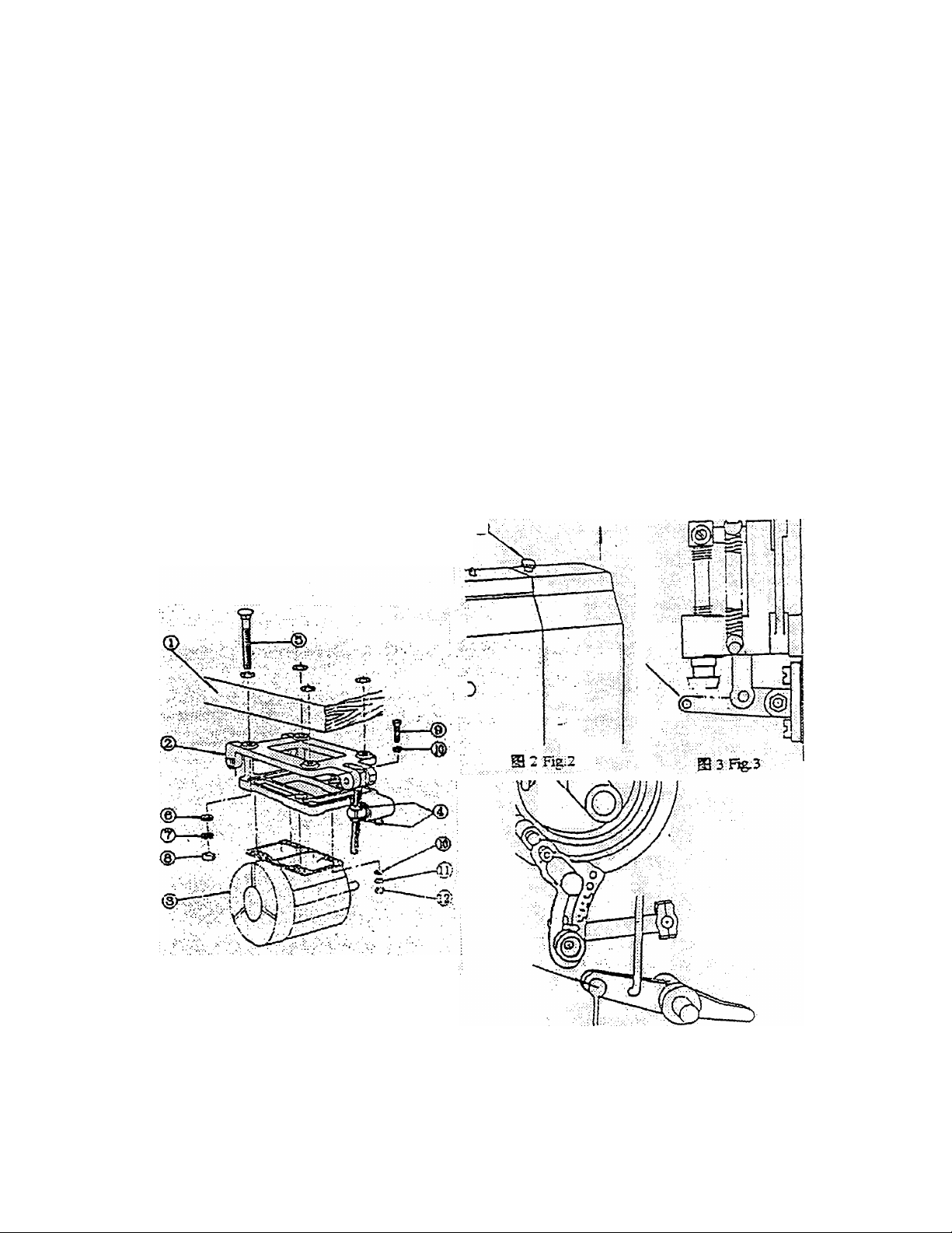
2. Fit button switch and motor to sewing machine table. To install the motor (as
shown in Fig.l), first fasten motor base (2) to sewing machine table by means of
bolts (5), flat washers(6),spring washers(7) and hexagon nuts(8),then fasten the
motor(3) to motor base (2) by means of hexagon bolts(9),flat washers( 10),spring
washers(ll) and hexagon nuts(12).
3. After completing the assembling of machine frame and table, install the machine
head. First loosen screw (1) to remove rear cover (as shown in Fig.2), then fasten the
machine head to sewing machine table by means of four long bolts.
4. To install the belt.
The belt connecting the motor with the sewing machine head should be tightened
properly. Press belt with your thumb, and adjust the belt tension by turning nut of
motor base (4 in Fig. 1) so that the belt can be depressed 2-2.5 cm with a finger.
5. To install chains.
A. To install the chain for the starting lever: remove rear cover, hitch the S shape
hook of the chain to the hole located in the front end of starting lever (as shown
in Fig.3).
B. To install the chain for the button clamp lifting rod: remove hinged cover,
connect the straight hook with chain, and hitch it to the , connecting hook on the
button clamp lifting rod (as shown in Fig.4).
button clamp lifting rod (as shown in Fig.4).
Finally, connect chains with two treadles separately. To limit movement of
treadles, treadles fastened to the floor should be inclined strongly and chains should
not be too slack. The proper adjustment will make the operator less fatigue.
1.
2. о-,
шгвтш(5).
$igiEafe±: ,74:^*19(12)
3. з^&тж^кёШ(лв 2),шт1ши
(1),
4. ^±'(#й!]йФ.
(JE® 1 Ф(4)), 2-2.5стША^Ш
¡Ж^^'Й., (С
Ш 1 FSg.1
а 4:1%4;:
3 -

5.
A: №TJsm, 3),
s JgSi^S^Se^tElFiLrt.
B: i&jiffii®^fl<isfe: njf±m%, ^f&jiwtciF±w-ji^ir(jas 4);
V. Construction and Adjustments.
1. Starting and stopping.
The main shaft is driven by clutch mechanism, as shown in Fig.5.Depressing
treadle allows chain to pull down the starting lever (l),and bevel of wedge(2) will
drive pulley to engage to clutch wheel and turn the main shaft .Releasing the
treadle quickly after depressing, starting bracket(3) will not be released by hook (4)
until stop block(5) on the side of worm wheel pushing out stopping lever (6) at the
end of the 19th stitch. The clutch wheel is disengaged while brake stop (7) will
move upward and apply pressure to the pulley to slow down the main shaft. As the
needle finishes the 20* stitch (the motion is now actuated by the inertia of itself
only), the speed is considerable lowered, so that enabling the stop bolt (8) plugging
into notch as a positioner.
The pressure of brake stop (7) can be adjusted to create a "soft" stop. While the
machine has been spared in use for several hours and is again to run there always
happens that the notch can not be reached while stopping. This will come back to
normal after several trials on running under no load. Therefore, there w'ill be no
need of further adjustment afterwards.
1.
(1
jv7
M 19
2. The starting safety pawl.
To avoid accident caused by careless operating, a safety device is installed at rear
of the machine. The main part of the device is starting safety pawl (9) (as shown in
-4-
mmTjB
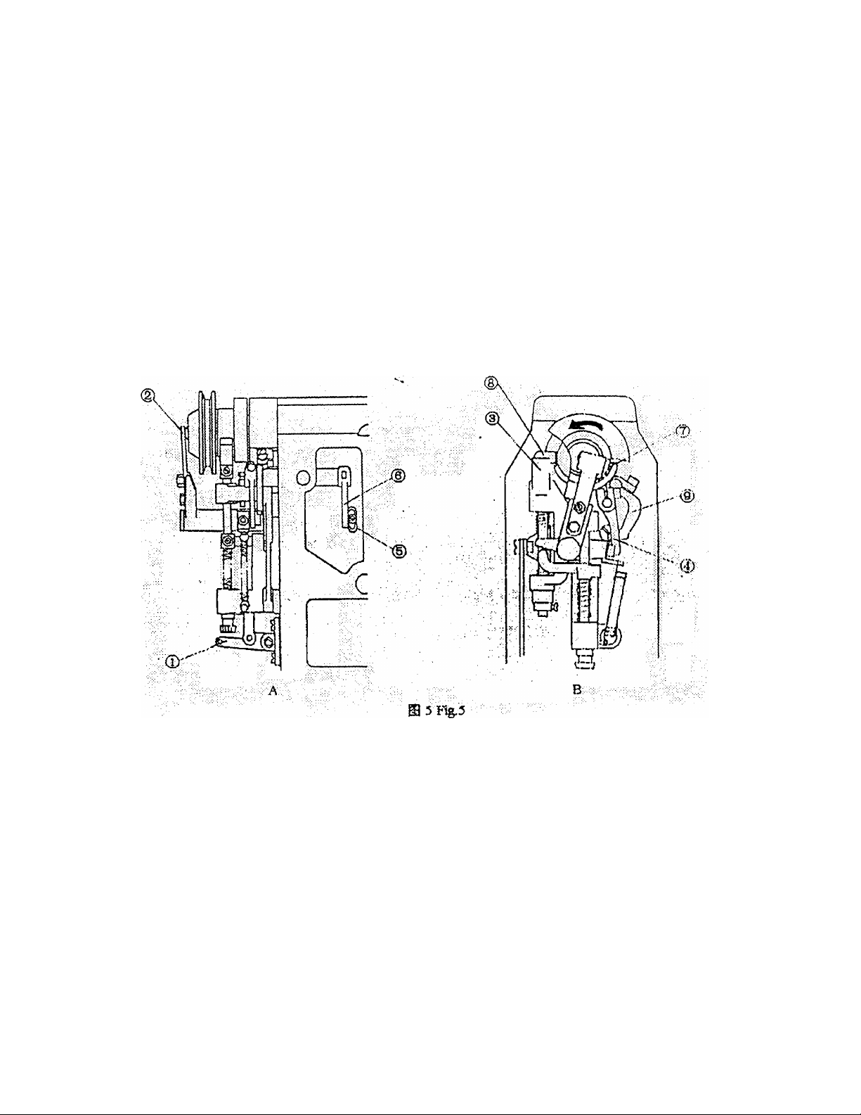
Fig.5).
The starting safety pawl should prevent the work clamp from being lifted when
machine is in operation and should prevent machine from starting when button
clamp is raised. This will prevent needle, looper and thread trimmer from being
damaged.
2.
—JESSi'O).
BtJtJi'o
3. The relative position of needle, looper and spreader.
A. The relative position of needle and looper.
First set the needle properly, as shown in Fig.6, loosen screw (1) and insert
needle (2) up into needle bar as far as it will go with its short groove A of needle
facing away from the operator. Securely tighten needle clamping screw (1). Turn
the machine pulley until the needle bar moves down to its lowest position. When
the needle bar is in this position, needle point should be at the centre of the looper
shaft, as shown in Fig.7.Turn the machine pulley to raise the needle bar about 3-
3.5mm from the lowest position, point of looper should reach the centre line of
needle. The point of the looper should be about 1mm above the top of the needle
eye.
-5-
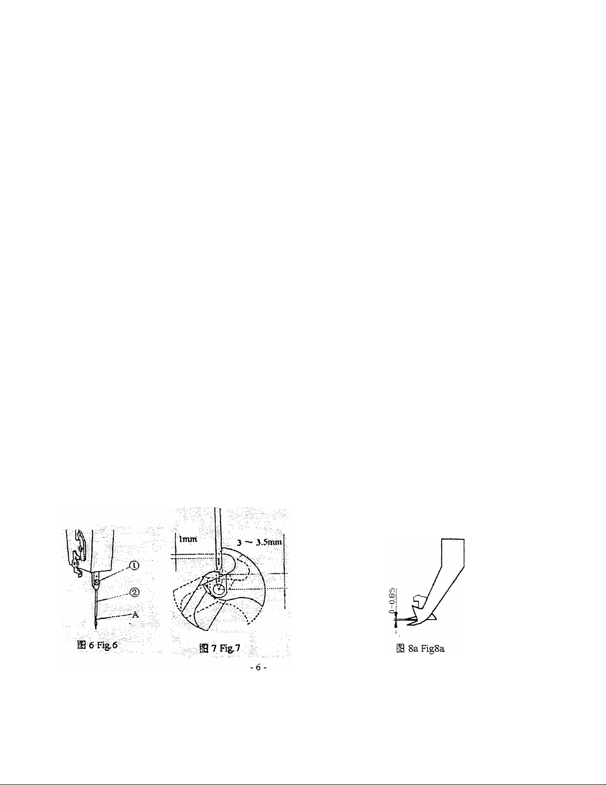
In the above-mentioned position, there is a very slight clearance between the
point of looper and needle. It is necessary that the needle pass 0.1-0.2mm to the
needle guard, but widiout actually rubbing against it. (see fig 8). Notice: The
clearance between needle and needle guard should be the same when the needle is
swinging right and left.
B. The relative position of needle, looper and spreader.
Turn the needle down from the highest position until needle point is in line with
the bottom of spreader. Then the spreader should be in a state of relative rest while
the needle will continue its downward stroke until the lowest position. The needle
will move upward from the lowest position to such a position where the spreader is
beginning to swing (but still in a state of rest). In such a position, the clearance
from the point of looper to fork of spreader should be 0-0.85mm.Loosen set screw'
of spreader to adjust.(see fig 8a).
3.
A:
A jtkBt:|§#ffi5g!]Sate®aW. It
3-3.5 mm, WAiftife'iiii
It Jlii 1 S it:.
B: #llt, ^lt-^tt^X6<jtS5it'aa:
gbs*-'i4a. ittBi^itii:
si5iiffi®5tsxxnsi^j®w o~o. 85 «it.
L_1
S Fig.8'
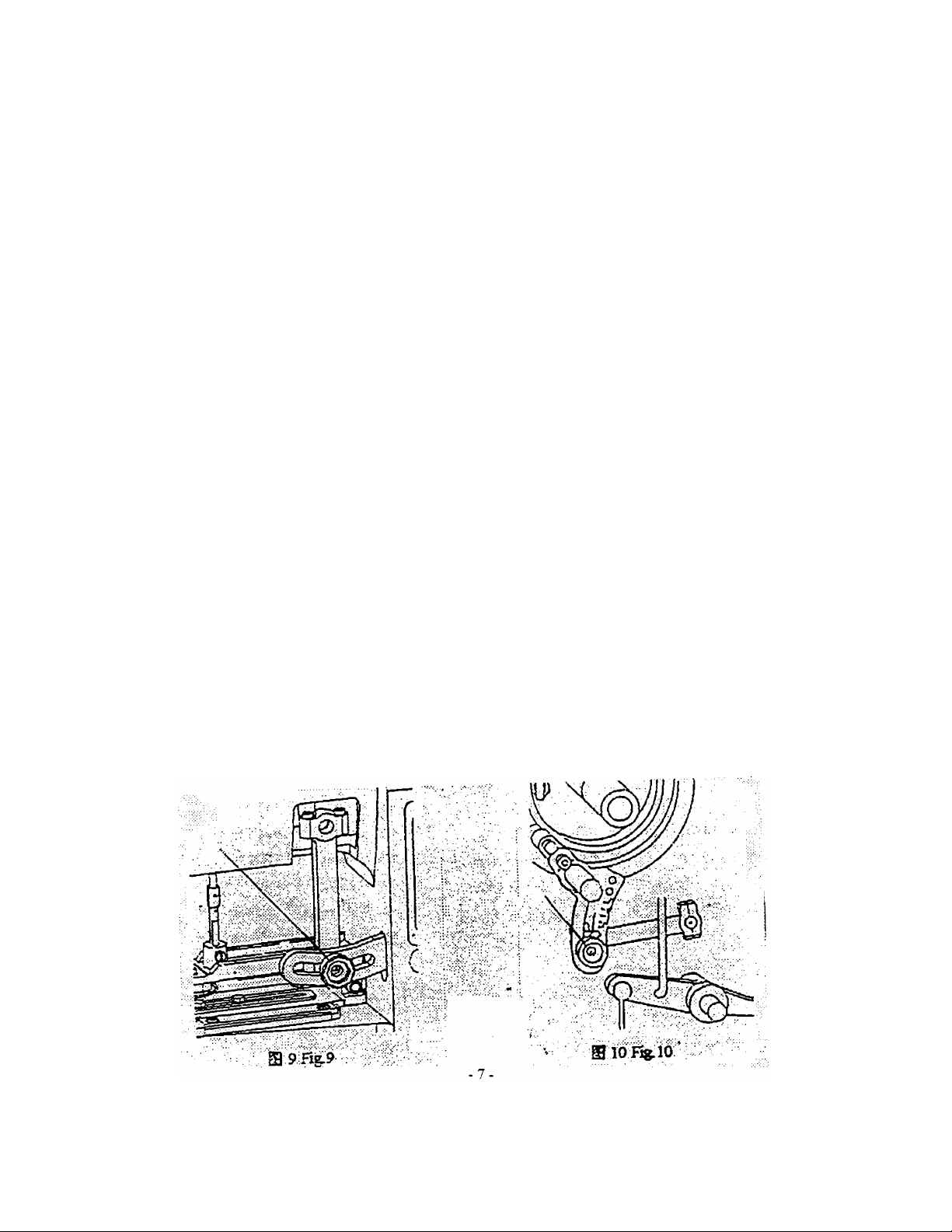
4.To adjust the needle position above button.
The needle must fall in the center of holes in the button. There are two steps to
adjust Lateral distance of buttonholes is controlled by needle vibrating crank. When
connecting rod is nioved out, lateral distance will be increased, and vice versa. As
shown in Fig.9.Longitudinal distance of buttonholes is regulated by needle crossing
crank. When its connecting link is moved downward, the longitudinal distance will
be increased, and vice versa. When the link is at its highest position, the longitudinal
distance is zero, the machine is to attach two hole buttons, as shown in Fig. 10.
If the needle can not fall in the center of holes in the button due to improperly
installed button clamp, then the button clamp must be adjusted. Loosen two hexagon
screws (1), and move the button clamp properly (as shown in Figll). Check if the
needle falls in the center of hole in feed plate before adjusting the button clamp.
The position of needle above the button is closely related to sewing performance.
Make absolutely certain when adjusting. To adjust the button clamp for the size of
button to be sewn on, choose good quality button and insert it in the clamp, pushing it
as far as it will go. When the button is correctly placed into position in the clamp,
depressing the threadle to release the button clamps. Put material under the button
clamp if it slides after falling down jfreely. Turn the main shaft slowly to bring the
needle to the centre of each hole in thé button.
When buttons of different sizes are to be sewn on one suit at the same time, the
distances from center to center of two kinds of buttons should be close. Adjusting the
button clamp in accordance with the small button, and the needle may not fall m the
center of holes in big buttons, as shown in Fig.l2.Notice: Don't let needle contact with
the hole periphery of the button.
4.
Bg€iQ. jaS lOo
W::^7L4'I'bH4*.
®X= iSliBFS'ii®iil55,?L??TMS^h
-laa^iESSi^te, itii
TFSieflEffliafS,
—?Lii.
-•fr^ie ffl [s] Bt ii A€ ia »ffl ft r: #
sli&fii, S5}£z:l4'€ft№?Li&Si®i5.
S nFig.ll
,E® 12. S.ST'gihm#i«mii»
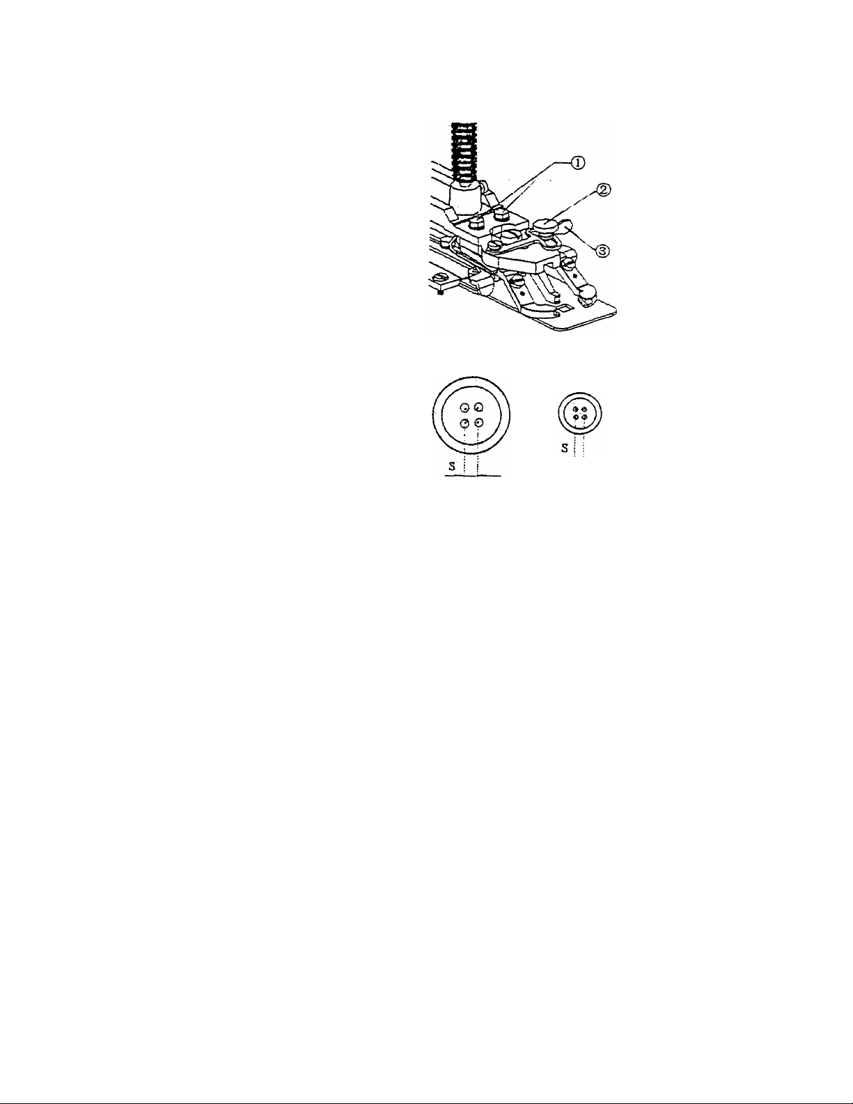
5. Adjusting button clamp (as shown in Fig.ll).
a 12 Fig. 12
The button clamp is suitable for attaching two or four or bar buttons of 9-26mm in
outside diameter.
To adjust the clamp jaws, loosen screw (2), pull back the button clamp adjusting
plate (3), and adjust the clamp jaws to the desired width, then securely tighten the
screw. The width between clamp jaws with button should be slightly smaller than
width between clamp jaws without button. It is easy for the button to be inserted or
taken out. If the opening of the clamp jaws is not wide enough, it is difficult to insert
button in and at the same time will cause unnecessary wearing of the clamp.
5. €*№iSS(JE@ 11)
*.^€^iSl:iT 9~26mm S-gfl^Higgi-ilCft.
ta □ X A №isif. ssft'siii (2), ffl€*i®(3), □ isii sj
6. Threading and thread tension discs (as shown in Fig. 13).
Thread the machine in accordance with the diagram as shown in Fig. 13.Threading
improperly will affect the sewing quality directly.
There are three thread tension discs installed at the top of the machine and each of
-8-
 Loading...