

Page 1

INSTRUCTION MANUAL
AND
ILLUSTRATED PARTS LIST
FOR
SINGER
MACHINES
1371A1
1371A2
1371A3
THE SINGER COMPANY
Page 2

Page 3

Contents
ffiffliiiBfl
Instruction...................................................................................................................................... 1
Illustrated Parts List
1.
....................................................................................................................................42
Frame and Miscellaneous Cover Components.......................................................................................43
2.
Main Shaft Components...........................................................................................................................44
3.
Hook Driving Shaft Components........................................................................................................ 45
4.
Presser Bar Work Clamp Carrier Components...................................................................................... 46
5.
Needle Bar Frame Components...............................................................................................................47
6.
Overedging Width Adjusting Components
............................................................................................
7.
Needle Thread Trimmer Components.....................................................................................................49
8. ШтШ'Ш
Bobbin Thread Trimmer Components ■
........
.........................................................................................50
9.
Knifebar Components...............................................................................................................................51
10.
Feed Cam and Tripping Segment Components
11.
....................................................................................
Stop-Motion Components..................................................................................................................... 53
12.
Tripping Lever Components.................................................................................................................. 54
13.
Thread Tension- Components................................................................................................................55
14.
Lubrication Mechanism Components....................................................................................................56
15.
Speed Transmitter Components.............................................................................................................57
16.
Motor Pulley Components......................................................................................................................58
17.
Machine Head Accessories......................................................................................................................59
18.
Needle Safety Plate Components...........................................................................................................60
19. Ш1Ф
Accessories............................................................................................................................................. 61
20.
Table Cutout Drawing............................................................................................................................62
48
52
Page 4

INSTRUCTION MANUAL
Page 5
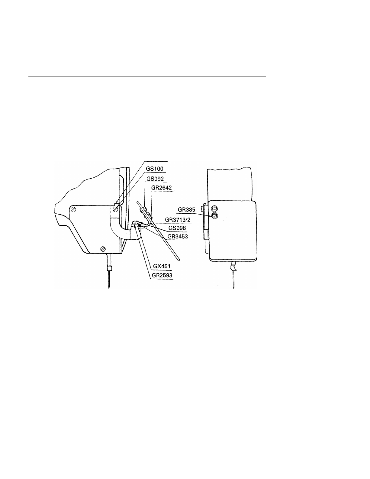
^HOW TO INSTALL THE SAFETY^ PLATE ^
a. ^®TjN^g,
Install the safety plate at the position shown in the figure by means of safety plate
installing bracket set screw.
GR3715
Page 6
INSTRUCTION FOR SET UP
1. ##Hl^!Sa
1. Screws used for set up Pig.a
® ® ©
F zfzinSBBlEW»
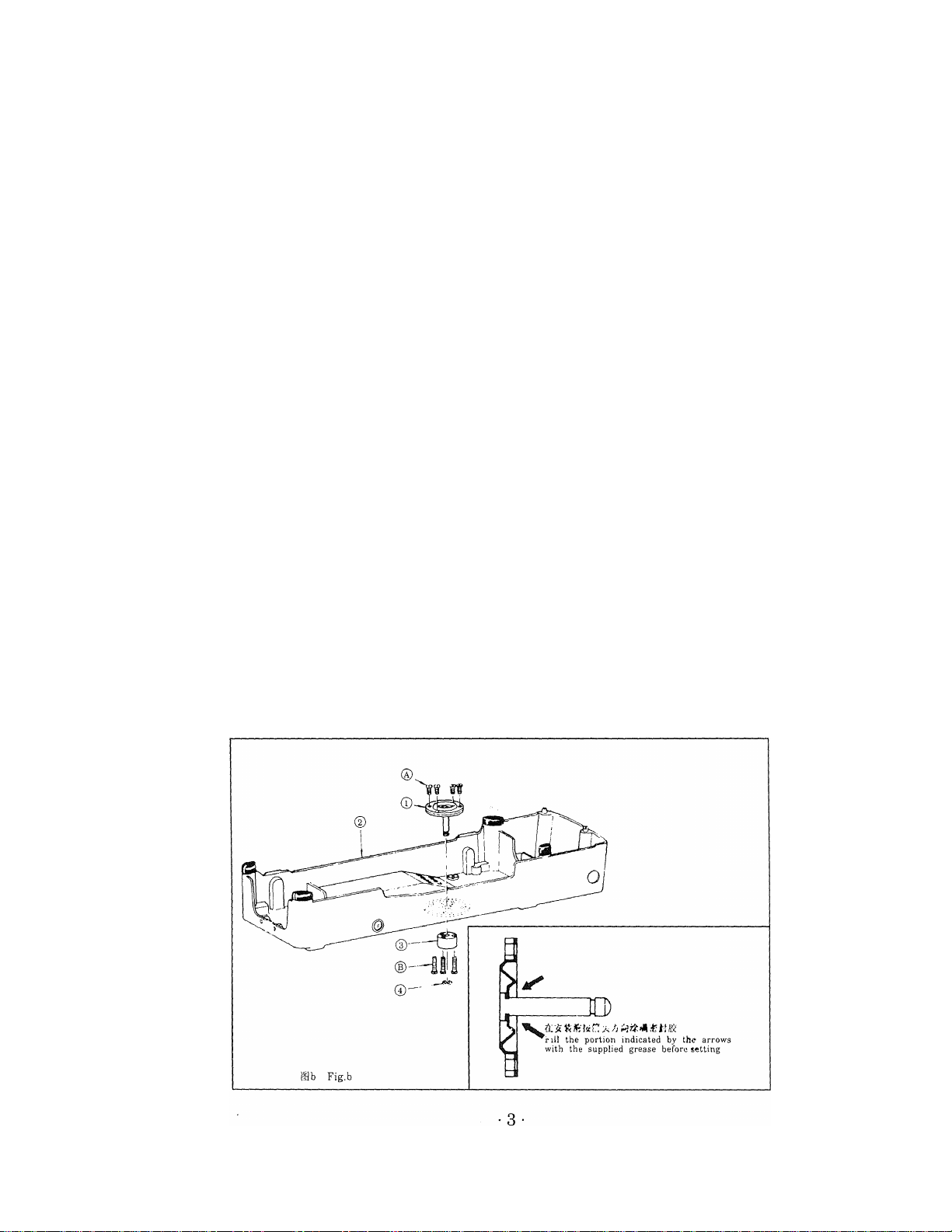
2. ^iiiSS]5ffSI5ftKlSse:
fSo
2. Attaching the shifter driving pin (asm.)
1) Fully apply the supplied grease to the pin of the shifter drive pin (asm.)® and the
Ba Fig.a
rubber surface on the rear see Figure Fig.b
2) Using screw ® , fix the shifter driving pin (asm.) on machine head base ©.
3) Using screw ®, fix driving pin base ® on the rear surface of the machine head base
so that the shifter driving pin moved up and down smoothly.
4) Install snap ring ® on the shifter driving pin (asm.).
Page 7
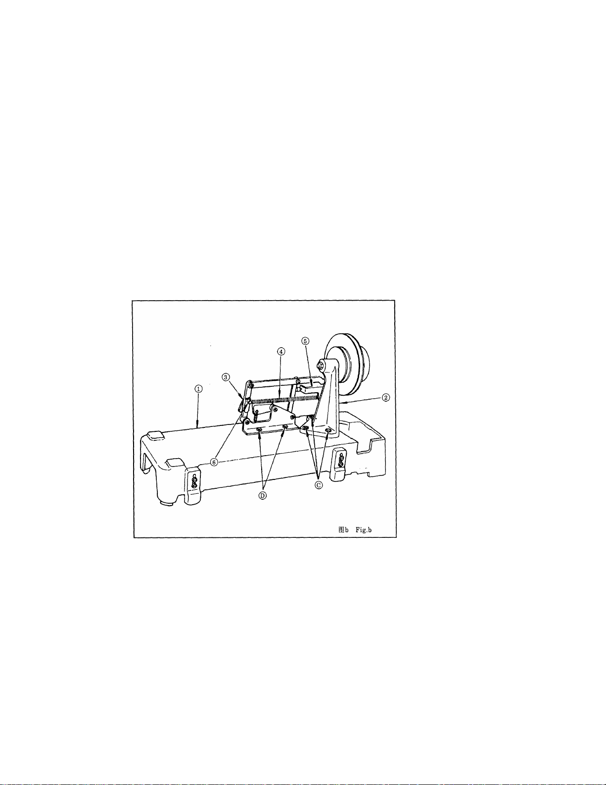
3. Sc
2)Mli4T
3 Installing transmitter (asm.) and shifter base (asm.) pig.c
1) Place machine head base ® with its rear surface facing toward you.
2) Fix transmitter (asm.) ® by screw ©
3) Fix shifter base © by screw ®
4) Attach shifter tension spring ® to shifter stopper bracket (asm.) © and shifter tension
spring bracket © of the shifter stopper base (asm.).
4. sd
4. Supplied with the reducer (asm) Fig.d
1) Fix tension pulley coupling © by hexagon screw © supplied with the reducer (asm.).
2) Install stud © and machine head base seat felt © on machine head ©.
3) Fully lubricate the shifter driving pin and the driving pin base again. Also lubricate
the end of the shifter driving pin and the head of the screw of the shifter pin bracket.
Page 8
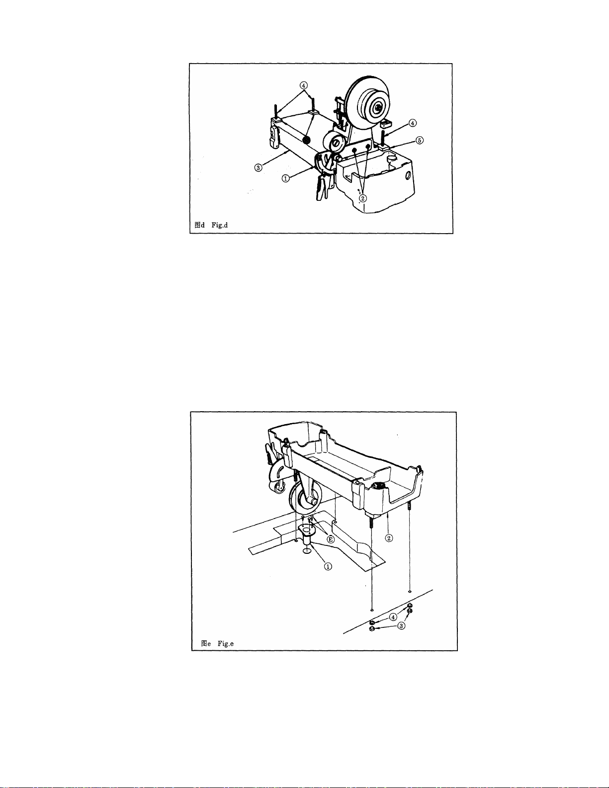
5.
mMmj i>25mwmin±o
#o
5. Installing the machine head base (asm.) Fig.e
1) Fix drain funnel Q to the drain hole (<^25) in the table by wood screw ®.
2) Placing the machine head base (asm.) on the table, fix it by tightening nut ® (flat
washer ® is used) from the bottom of the table.
Page 9
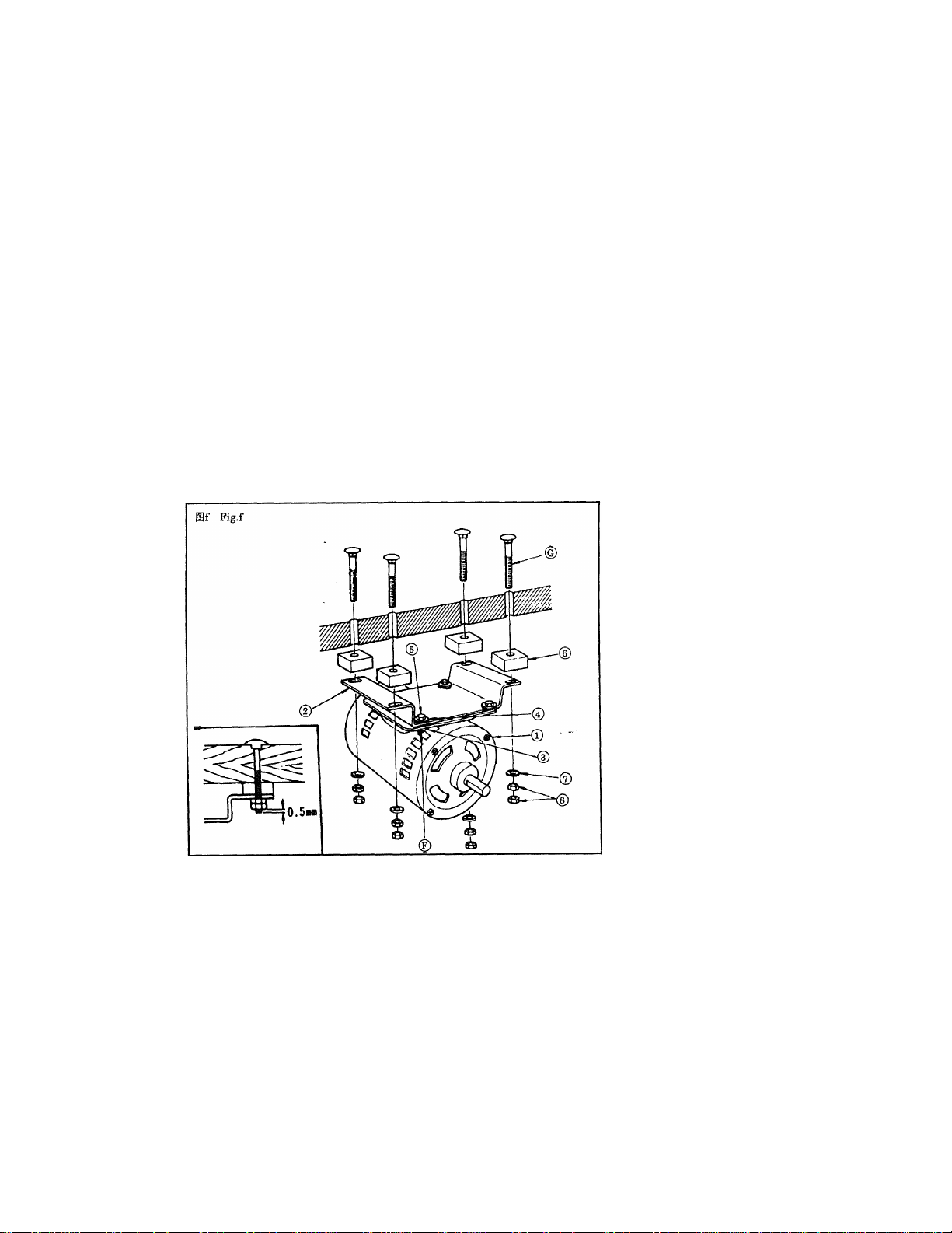
6.
itmi^, ©iit^;5&<}#HiiM;^^0.5mm(«^)o(#
6. installing the motor Fig.f
1) Install motor ® on motor base © by screw © (flat washer ®, spring washer ®, and
nut® are used).
2) Placing spacer ® between the table bottom and the motor base, fix the motor base by
installing bolt © (a flat washer ® and nut ® are used).
Tighten the nuts so that the lower nut is levelled with the end of bolt © or bolt ©
projects by 0.5 mm.
Page 10

à-''.,
yi ■ i ■'■ "i. .
rT7'rc=^l^'' *^-
i‘ '" -BSt':-
2) ÿè -^: rt ^ j]p ')È ^ tb ?f i o
CAUTIONS IN OPERATION
1) The machine should rotate counterclockwise as observed from the pulley. Take care
not to rotate the machine in the opposite direction.
2) Never start the machine before filling the machine base with lubricating oil.
3) Remove the bobbin case and the needle thread from the machine before performing the
trial operation.
4) Clean up the sewing hook and the bobbin thread trimmer every day after sewing work.
Also check the level of the lubricating oil.
5) Never bring your fingers or hair close to, or place anything on the handwheel, V-belt,
bobbin winder wheel or motor during operation. It may lead to serious personal
injuries.
6) If your machine is provided with a belt cover, finger guard and eye guard, never
operate your machine with any of them removed.
.
1. MOTOR PULLEY AND V BELT ^
Wà
2ç>omi6ï
3000$^/5h
2600$t/5h
3000$^/5->
50HZ GD370 GE137 GE137
50HZ GD370H
60HZ
60HZ
GD370HH
GE136
GD370L GE137L
GE137H
VMlÈÎiïiftiS)
GE137
GE137
GE137
Page 11
1) Motors of 370w, 4-pole are used three-phase operation. (If a 250W motor has to be used
for single-phase, operate the machine at 2600 s.p.m. or less, according to order form)
2) M-type V belts are used.
3) Refer to the following table for the motor pulleys, V belt, and sewing speed.
Sewing speed Frequency
2600 s.p.m.
3000 s.p.m.
2600 s.p.m.
3000 s.p.m.
50HZ
50HZ
60HZ
60HZ
Motor pulley Part No.
GD370 GE137
GD370H GE136
GD370L GE137L GE137
GD370HH GE137H
High speed
Vbelt
Low speed
Vbelt
GE137
GE137
GE137
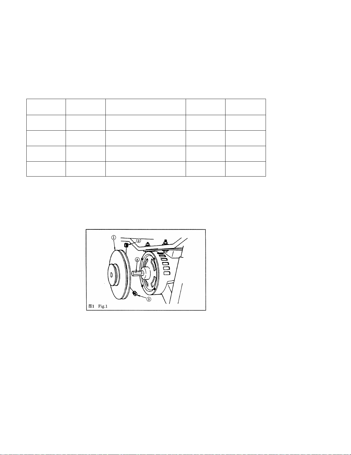
* How to install motor pulley pig.i
Place motor pulley ® into the motor shaft so that flat part ® of the motor shaft aligns
with first setscrew ©. Then securely tighten setscrews © and ®.
* ®2
BP^o
* How to install V belt pig.2
1) Mount high-speed V belt © on accelerating pulley © and the large diameters of the
motor pulley.
2) Mount low-speed V belt ® on low-speed pulley ® and the small diameters of the motor
pulley.
•8-
Page 12
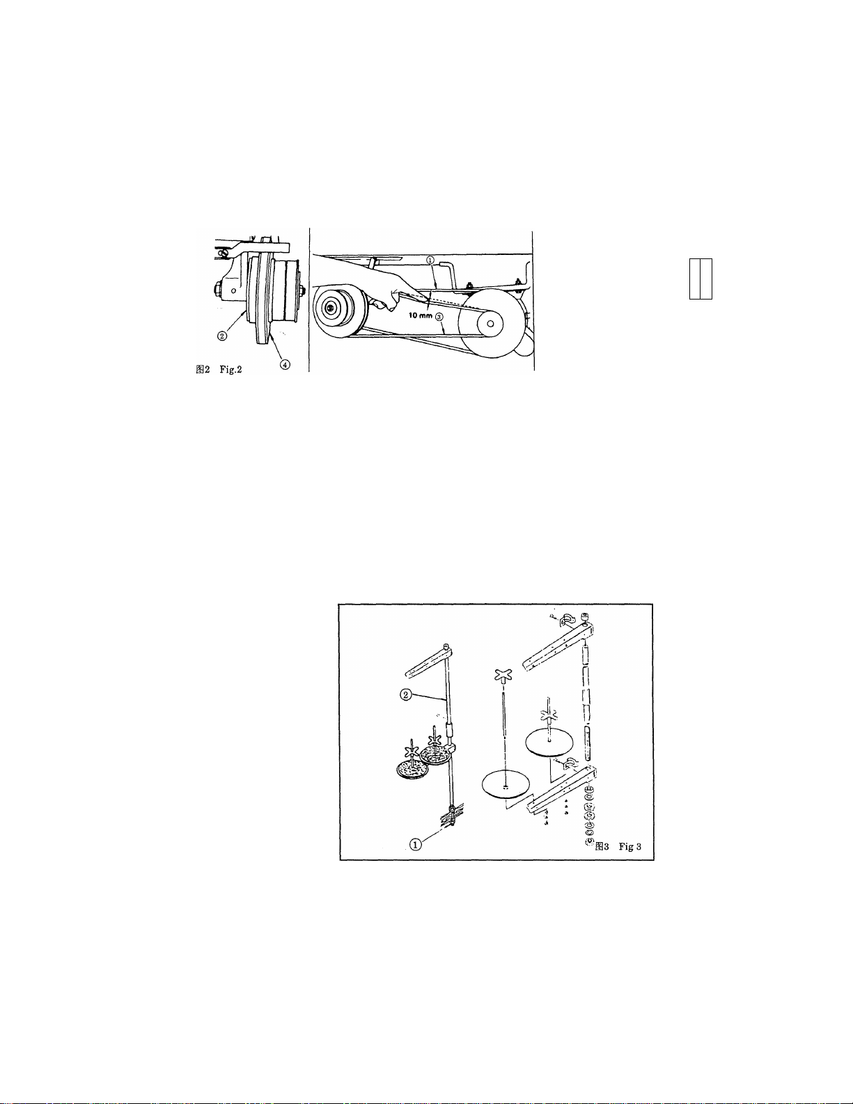
3) By moving the motor from side to side, adjust the tension of V belts ® and ® so that
they give an approx. 10 mm slack when their middle portions are pushed lightly by
hand.
4) Move the motor pulley back and forth to align V belts ® and
7?
JSU«
Motor pulley
r jp, • s. ;■ «• -
A
2. SETTING UP THE THREAD STAND Figs
Assemble the thread stand, and fix it in the table hole. Then tighten lock nut ® to fix the
thread stand. If ceiling wiring can be made, pass the power cable through spool rest rod
(2).
Page 13
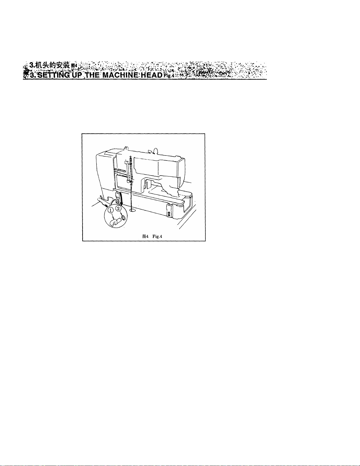
Putting cushion ® into hinge ®, insert hinge ® into the machine head. Then, place the
machine head on the machine base.
i ; i:''A?/
4. AtTACHiNdimE FLAT BELTFigi
siitwoin^sQsigigiih.
4)® Ain iftif ^11 c
1) Removing screw ®, remove spring @ from the suspension screw.
At this time, be careful not to push the starting link driving rod in the arrowed
direction.
2) Pass belt ® through belt shifter ® so that the belt rotates in arrow ® direction.
3) Reinstall screw ® and spring @.
4) Lift tripping lever ® in the direction, pass the belt between latch B (§) and latch A @.
10
Page 14
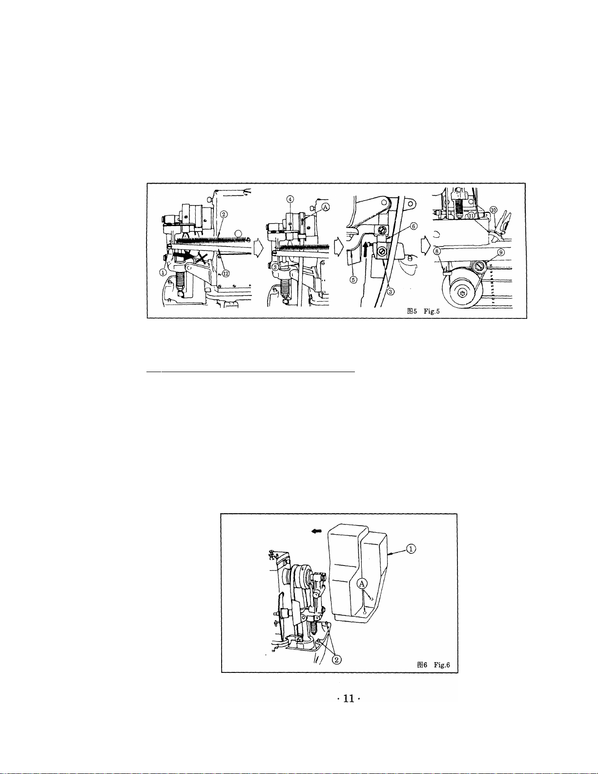
5) Passing belt shifter ® of the speed transmitter, attach the belt onto tension pulley d).
6) Put fixing pawl @ in the second groove from the bottom of ratchet © to provide the
belt with tension.
(NOTE) Some expansion or contraction in the belt caused by temperature or humidity
may make it rather difficult to install the belt. However, the belt will restores its
original length while in use.
5,
5. INSTÀLLÀTION/REMOVÀL OF BELT COVER Fig.6
Aligning guide pin @ with hole ® in belt cover ®, push the belt cover in the arrow
direction until it snaps.
For removal of the belt cover, bring down the belt cover in the direction opposite to the
arrow, and slide it up.
Page 15

l>l#Singer ”^ito
lUTBiiS'^iPyi o
* ®8
^zwmimo
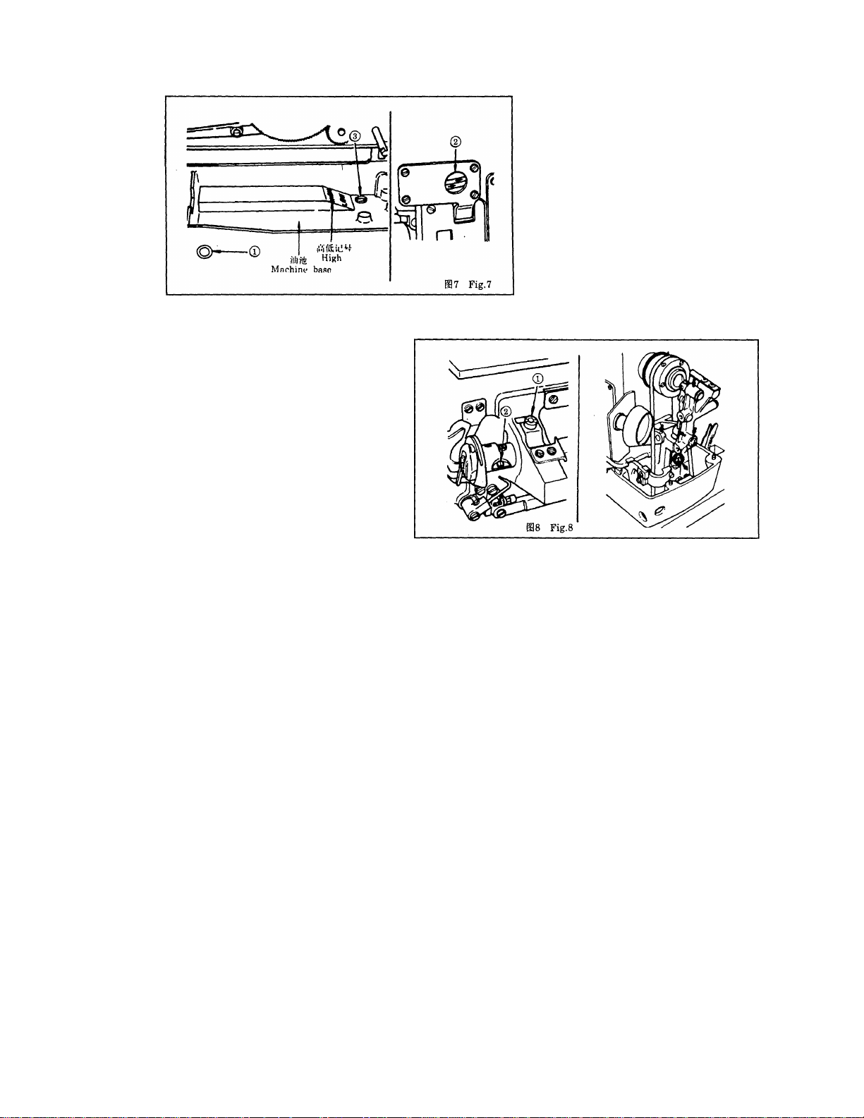
* Before starting the machine: Fig ?
1) Fill the oil reservoir of the machine base with singer oil type C up to the level indicated
by "HIGH”.
2) Supplement the oil when the oil level has lowered below the bottom line of oil gauge
3) When the machine has been properly lubricated, the oil is seen to run through the pipe
from oil sight window (D. (Low speed operation permits easier observation of the
lubricating oil.)
Drain dirty oil by loosening oil drain screw ®, and fill the oil reservoir with fresh oil.
* Adjusting the lubrication for the sewing hook Fig.s
Adjust the volume of lubricating oil supplied to the sewing hook by turning oil adjusting
screws ® for rough adjustment, and (D for fine adjustment; oil volume is reduced when
turning the screws clockwise.
* Other lubricating points
1) Apply one or two drops of lubricating oil to the arrowed points once a week or every
other week.
2) Apply two or three drops of lubricating oil only to (S) point when the machine is
newly set up or has been out of use for a long time.
12
Page 16
7. HOW TO INSTALL THE'NEEDLEFig.9
* *ta®Mmttftlj586iafflttSingerN-1955
ilm«o
* Turn off the motor power. Use needle cat. No. 1955-01.
1) Loosening needle setscrew ®, hold needle ® with its recessed part facing toward the
operator,
2) insert the needle fully into the needle clamping hole, and
3) securely tighten the needle setscrew.
13
Page 17
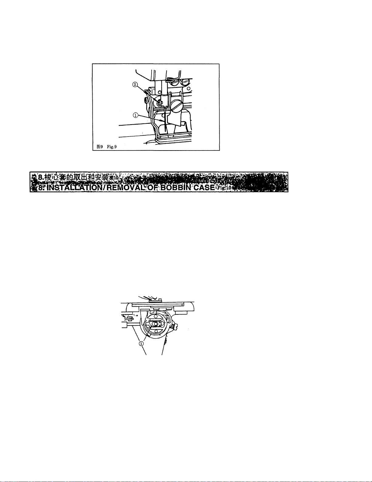
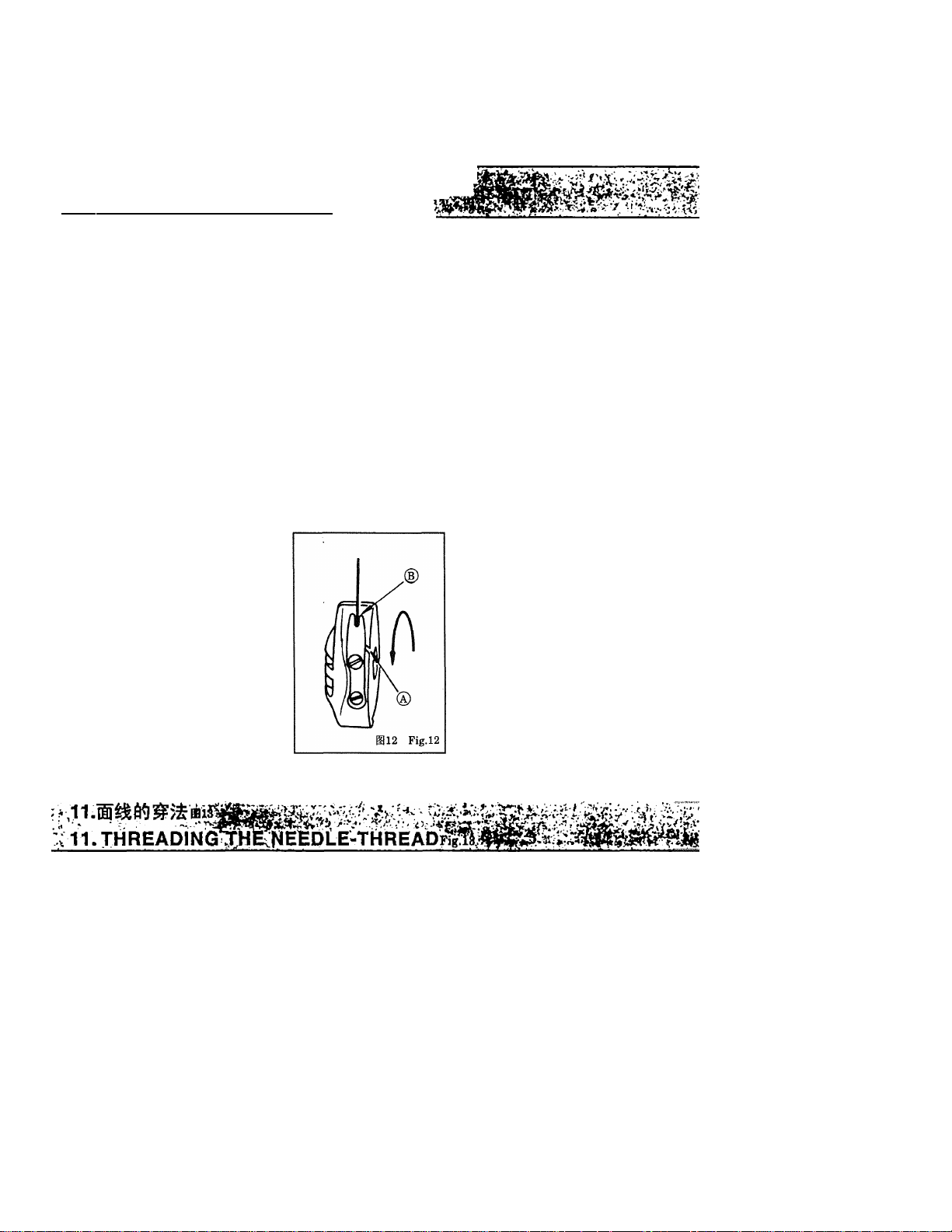
1) Lift up and hold bobbin case latch lever ® between two fingers to remove it from the
hook.A bobbin does not fall off the bobbin case while the latch lever is lifted up.
2) For installation of the bobbin case, push the bobbin case into the hook so that it is
supported by the hook shaft, and then snap in the latch lever.
SlO Fig.lO
14
Page 18
mil '■
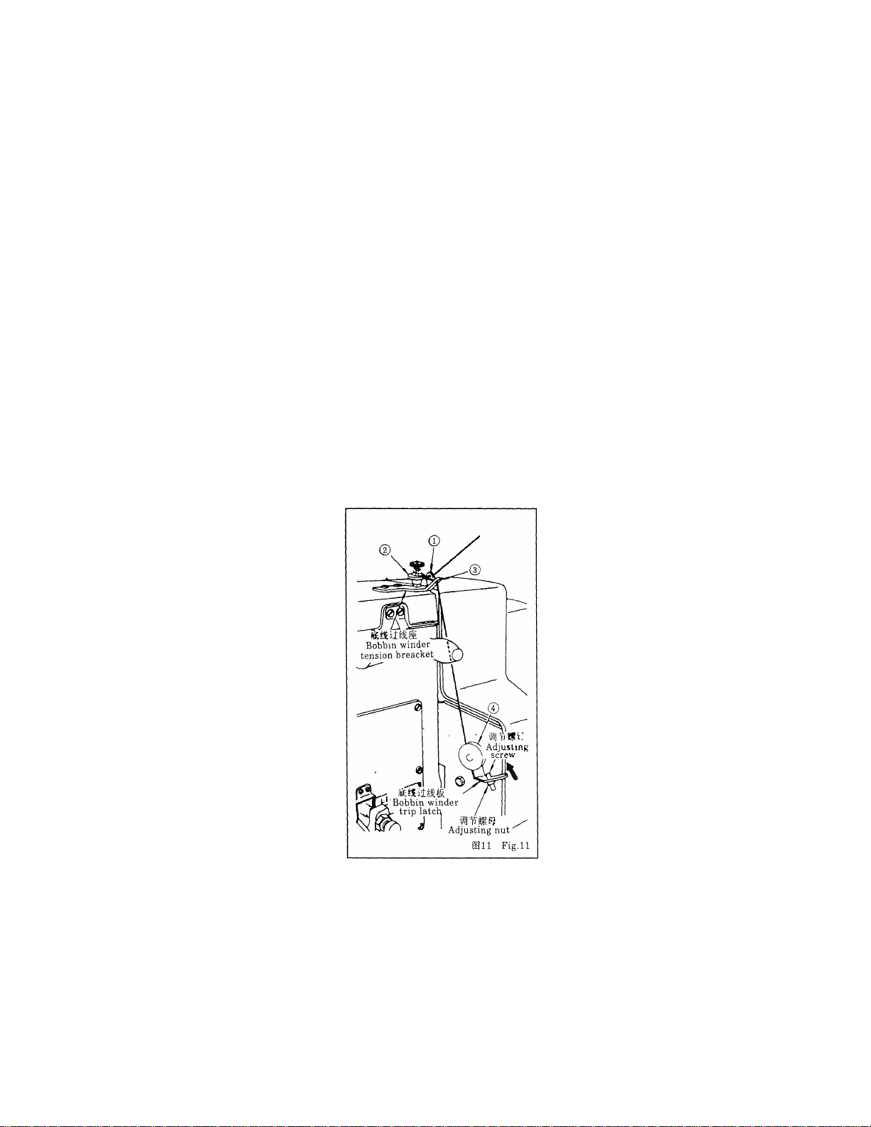
9. WINDING THE BOBBIN Fig.ii
i5iiiaiSK«Titi#, #iHT!titiiiciDgK®a*ijiTi.
5)';^m&is\¡¡¡-9m, ttjtitiiEffiiSiSisfts.
1) Fit a bobbin onto the bobbin winder shaft.
2) Take the thread from the spool and pass it through the guides in the numerical order
shown in the figure, and wind the end of the thread several turns around the bobbin.
3) Push the bobbin winder trip latch in the arrow direction, and the bobbin will be wound.
4) Loosening the adjusting nut, perform adjustment by screwing in or out the adjusting
screw so that the bobbin is wound about four-fifths full.
5) If the bobbin is wound unevenly, adjust the position of the bobbin winder tension
bracket for proper and even winding.
15
Page 19
T/i •*■__!- -
’16. AtfACi^Nil fHe BOBBiN fI^
1) Hold and place a bobbin into the bobbin case so that the bobbin is wound
counterclockwise.
2) Passing the thread through thread outlet ® of the bobbin case, pull the thread, and
the thread can be drawn out from thread outlet (b),. passing under the bobbin winder
tension spring.
* Set the bobbin so that it rotates in the arrow direction when the bobbin thread is
pulled.
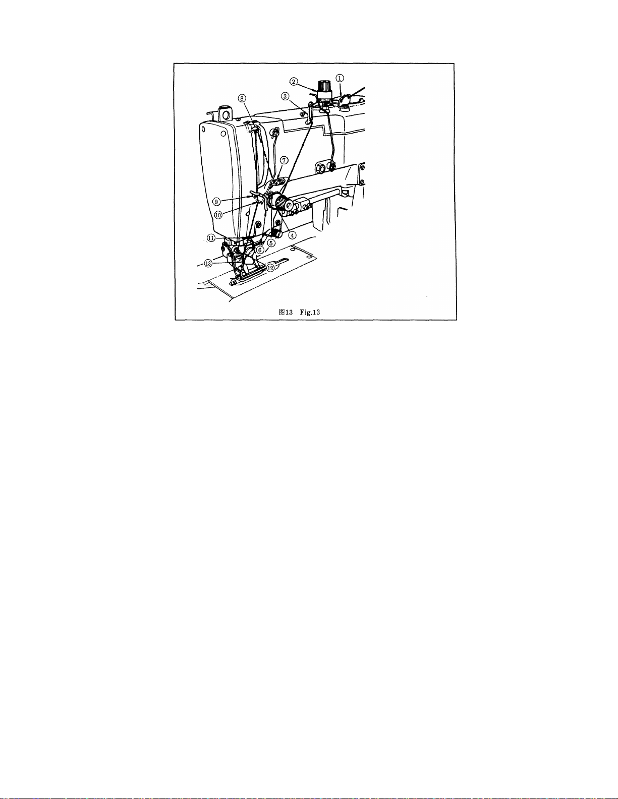
1) Pass the needle thread in the order as shown in the figures.
16
Page 20
12. REDUCTION OF SEWING SPEED AND EMERGENCY STOPFigH
®^go
2)mWALBP^/^jg;3Ii5ito
*
®^go
2nmm±m9^o
* Reduction of sewing speed
1) Turn hand stop crank ® downwards to position ®, and
2) the machine will be immediately slowed down.
* Emergency stop
1) Turn the hand stop crank downwards to position ® , and further upwards to position
® and
2) the machine will stop immediately.
17
Page 21
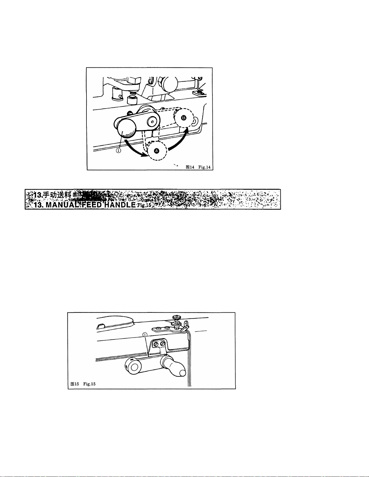
When you want to feed fabric manually after giving an emergency stop or to resume
sewing from the point at which thread was broken, rotate manual feed handle © to
operate the cloth feeding mechanism.
(NOTE) Confirm that the needle does not stick in fabric before turning the manual feed
handle.
18
Page 22
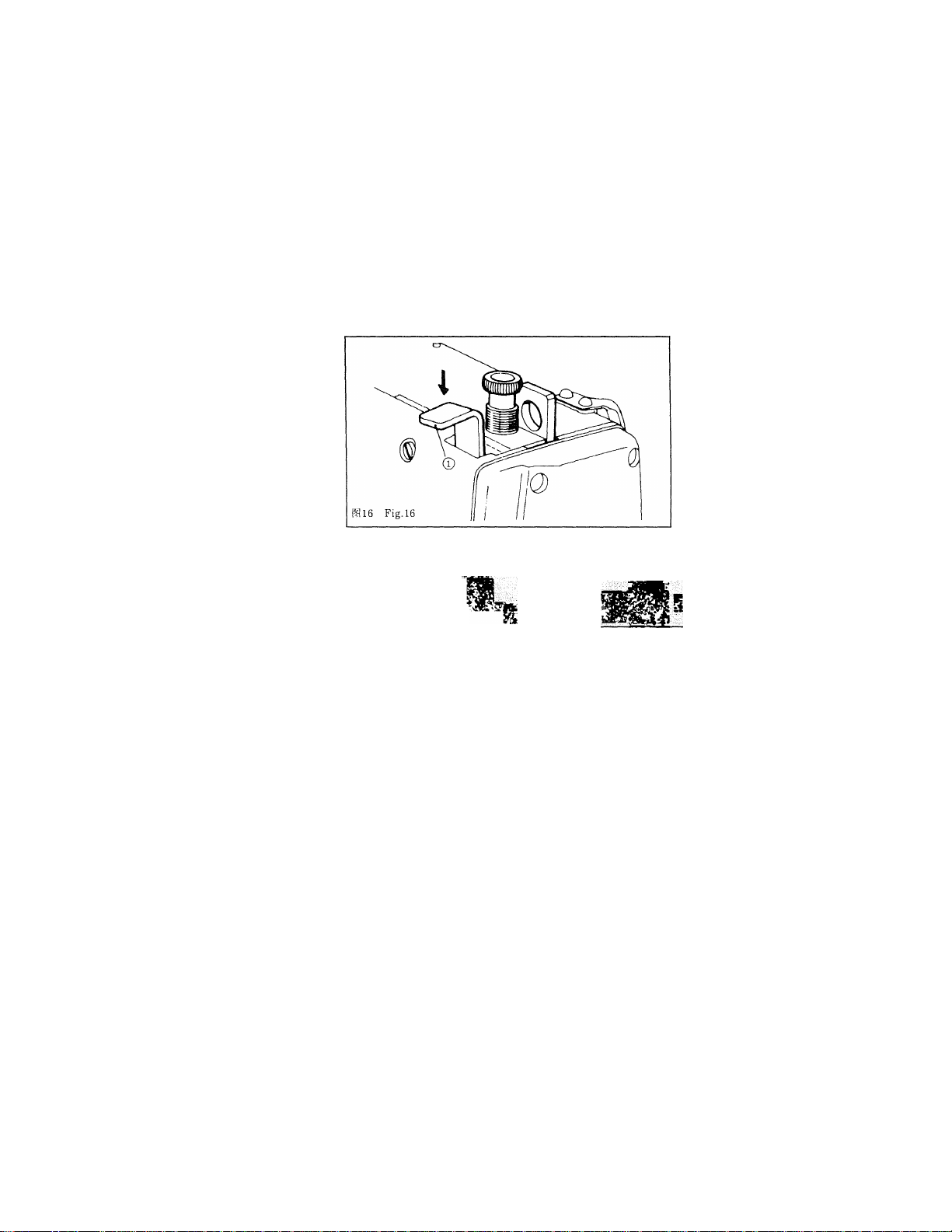
i4.Rif±t;o7iPf BB16
14. HOW TO HOLD THE DESCENDING KNIFE Fig le
When you do not want to cut fabric after sewing because of thread breakage or some
other reasons, keep on pressing down knife stop lever ® lightly until the machine stops.
Then the knife will not descend.
BB17
15.TYPES OF STITCHESFig.i7
mmmm
iP-mmm)
This machine is capable of forming two different types of stitches, namely whip stitch and
purl stitch.
(Whip stitch)
The whip stitch is formed in zigzag showing the needle thread only on top of fabric, and
the bobbin thread on the bottom.
(Purl stitch)
When applying higher tension to the needle thread to permit it to pass straight through
fabric, the purl stitch is formed by the bobbin thread which is pulled over from both sides
to the center line.
19
Page 23

Whip stitch
Purl stitch
16.THREADyriNSiON Й8.18 . ^
* щшшйшт^мт^
Pallarel side seam
Bar tacking seam
ai7 Fig.l7
■ '.Л ::^’Л •
•' '■ ■ ‘ Л*'
(Ш2Ш^^-Р.ШШ)
* тшш(^шш)
тч1^т©^/>йй^йл^^шт®йш«й, тин
* Adjusting the thread tension for purl stitch:
1) Adjust the bobbin thread tension to approx. 15 to 20g by adjusting screw ® of the
bobbin case.
2) Adjust tension controller No. 1 ® for proper needle thread tension so that the bar-tack
part is formed by well-shaped whip stitches. If the tension is too low, bar tacking seam
may form thread knots on the rear face of fabric.
20
Page 24
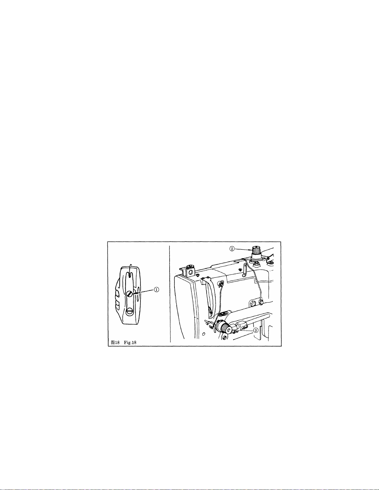
3) Adjust tension controller No. 2 ® for proper tension of the pallarel side seams by
judging from the stitch formation.
* Adjusting the thread tension for whip stitch:
1) Adjust the bobbin thread tension to approx. 40 to 50g by adjusting screw © of the
bobbin case.
2) Exchange the adjusting springs of tension controllers No. 1© and No.2 ® each other
(the tension controller No.2 will have a weak spring).
3) Adjust tension controller No.2 ® to prevent ravelling off at the end of a seam.
4) The stitches of the parallel sides or bar-tack can be adjusted by tension controller No. 1
®.
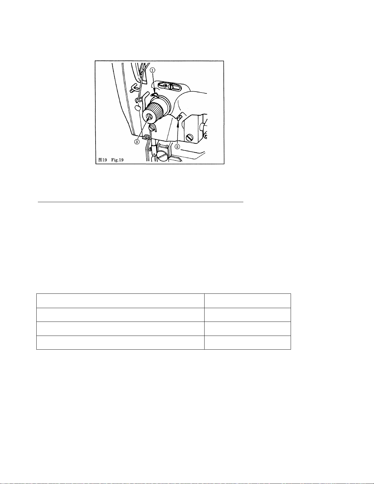
* Adjusting the thread take-up spring (for purl stitch)
The suitable range of the stroke of thread take-up spring © is from 6 to 8mm with a
starting tension of 20 to 50g.
For adjusting the stroke of the thread take-up spring, loose screw ©, and insert a thin
screwdriver into the slit of tension post © to turn the tension post.
To adjust the tension of the thread take-up spring, insert a thin screwdriver into the slit
of tension post ® to turn it, with screw © tightened. The tension of the thread tade-up
spring increases when the tension post is turned clockwise, and decreases when turned
counterclockwise.
21
Page 25
^17.' ADJUSTING THE OVEREDOiNG LENGTHiBUnONHOLE LENGi^
2) ffi »#«?№&«# ®, fflffi ®±ff . (-iaWZI «a« 1^ «ijs
it»!®«®.
3) -nLS.m, -№№ij]m]]7pmwL№i^^.
* ffiSftSWiSffl
iiaiSMi!i@*is«w«-!5igisiKijiw«ai#.
GM344/10
GM347/10
GM348/10
1) Pull out cover ®, and raise cover ®.
2) Loosen nut ® by the spanner supplied with the machine. Set point ® to a desired
length on scale ® (this length is the same with the knife width), and then retighten
nut®.
3) Through your trial sewing, adjust the overedging length accurately to the exent that
the bar tacking seams are not cut by the knife.
l/4"~3/4"
1/4"~1"
l/4"~ 1—1/4"
22
Page 26
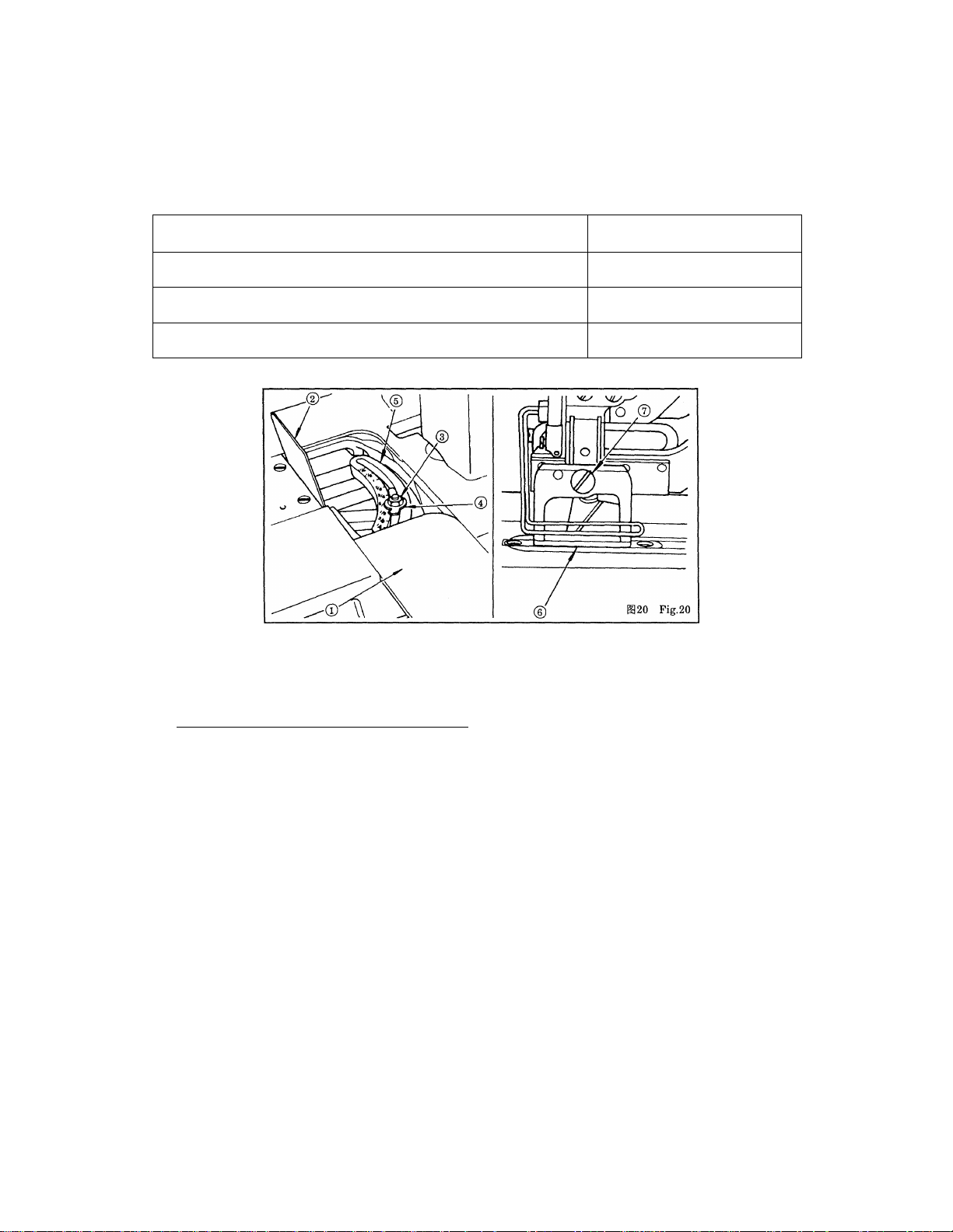
* Changing the work clamp check
Use work clamp check ® having the size nearly the same as that of a buttonhole length.
By removing setscrew ©, a work clamp checks can be changed together with a work
clamp check holder as a set.
GM344/10
GM347/10
GM348/10
Work clamp checkAVork clamp
check holder set Part No.
Applicable knife width
l/4"~3/4"
l/4"-l"
l/4"~ 1—1/4"
18. REPLACING THE KNIFE^g^a^
When sharpening or replacing the knife, remove it as follows:
1) Loosen setscrew ©, and remove knife © together with the washer.
2) Attach the knife to the knife holder so that the higher end of the slanted knife blade
comes down 2 to 3mm above the surface of the throat plate when the knife if brought
down to the lowest position.
(NOTE); Do not forget to install the washer when retightening the setscrew.
23
Page 27

'liTACKlNGiWIDfHyANb OVEREbGlil(^EreRENCE POSITIdNim^
№rn^mmnn^
mmn, K^siiirAiiiT®,
The needle swings from right to left with the right base line established as the reference
position.
Perform the adjustment as follows
1) To adjust stitch width ® , screw in or out screw ® , and set pointer @ to a desired
value on scale plate @. The actually sewn stitch width will be the half of the set scale
value (mm).
2) For adjustment of bar tacking width ® , screw in or out screw ®, and set pointer ® to
the value indicated by scale plate pointer @ , making the bar tacking width twice as
large as the stitch width.
24
Page 28

3) Adjust the position of right base line © by screwing in or out screw © so that it is
kept away from the cutting line of the knife. As screw © is screwed in, the right base
line moves to the left.
4) Through your trial sewing, further perform fine adjustment.
5) It is not necessary to adjust the position of left base line © since it remains
unchanged when the stitch width is changed. However, the left base line should be
moved to the left by screwing in screw @ if it is cut by the knife.
20. CHANGING .THE NUMBTER OF STITCHES
2)Bff^^^«iJWA.B.C
1371A3m±S$^H^*^,:^WG^.
..............
25
Page 29

-ia^
A 54
B
C 66
D
E
F 79
©
H
Pit 14^0
62
70
74
83
88 212
345 I
300
285 K
268
252
238
225
M
93
©
©
©
0
100
105
110
115
123
130
200
190
180
170
160
152
145
.
93f|-l^T
115#l^T
123#
* Spur gears
1) By selecting the spur gears, you can control the number of stitches as shown in the
table.
2) Alphabetical marks like A,B,C, etc,, and numerals like 123,152, etc. are both engraved
on each spur gear for identification.
3) Use a combination of gears which have the same alphabetical marks.
4) The numeral engraved on the gear installed in the rear position will represent the
fsiie©
10—12S4t
5i#:
0~2S^
26
Page 30

5) The machine head installed a couple of gears (symbol N)for 137lAl; The oter three couples
of gears (symbol G, J, L) are as accessories.
The machine head installed a couple of gears (symbol L)for 1371A2; The oter three couples
of gears (symbol J^ N) are as accessories.
The machine head installed a couple of gears (symbol H)for 1371A3; The oter four couples
of gears (symbol G, J, N) are as accessories.
Symbol No. of stitches
A 54
B
C 66
D
E
F
©
H
number of stitches provided by the combination of spur gears.
The circled alphabetical symbols in the above table show that the gears are included in
the standard accessories. All other gears are optional attachments.
* Attaching the spur gears to their shafts Fig.23
1) Push gear (D into the shaft so that it is securely fixed by the pin on gear bushing (D
located nearer to an operator.
2) For installing gear (D on the pin of rear gear bushing ® , push gear ® into the shaft
while turning it in the arrow direction.
62
70
74
79
83
88
No. of stitches Symbol
345
300
285
268
252
238
225
212
I
®
K
©
M
®
0
No. of stitches
93
100
105 180
110
115
123
130
No. of stitches
200
190
170
160
152
145
* Adjusting the low-speed cam position
Loosen setscrews (D, and adjust the position of low-speed cam (D to set clearance ® as
shown below:
Number of stitches
93 stitches or less
115 stitches or less
123 stitches
Clearance ®
10—12 mm
5 mm
0~2mm
27
Page 31

® 12mm <.
The presser bar goes up 9mm when the pedal is fully stepped down.
To adjust the pressure applied by the presser bar to fabric, turn presser spring regulator
®. When the pressure is not enough to prevent fabric from puckering, turn regulator ©
clockwise.
28
Page 32

22M
22. NEEDLE-TO-HOOK RELATION Fig25
(it
Ki A>1:.'^, fi^A0.05SA, c
i&M): uu'Jii:immf\-mw,
* Set the needle to hook relation in the following way:
1) Bring down the needle bar to the lowest point when the needle is coming down through
the center of the needle hole on the throat plate.
2) Loosen needle bar connection screw ®, and adjust the height of the needle bar.
(Setting the needle bar)
3) Insert the part 1” of timing gauge ® into the gap between the bottom end of needle
bar® and throat plate ® .
4) Retighten the needle bar connection screw to adjust the position of the sewing hook.
(Setting the hook)
5) Loosen setscrew ® of the hook sleeve by the bar spanner supplied with the machine.
6) Rotate the driving pulley in the correct direction until the needle starts to go up from
its lowest point.
7) Insert the part “2” of the timing gauge into the gap between the bottom end of the
needle bar and the throat plate, where the bottom end of the needle bar touches the
top of the part “2” of the timing gauge.
8) Align blade point © of the sewing hook with the center of needle @, and make
adjustment so that a clearance of approx. 0.5mm (1/64") is provided between the needle
and the blade point of the hook. Then, securely retighten the setscrew of the hook
sleeve.
(NOTE): If stitches are skipped, lower the needle bar by approx. 0.5mm (1/64")
from the timing gauge "1".
29
Page 33

ai26 , i; >
23. ADJUiSTING tHE BOBBIN THREAD WINDER Fig.2e
«a^aífeSSkíKSttSBí, ñTaii*K!Síi®*i)i
lío
1Í, nj.
Loosen screw @ to make adjustment so that the clearance between bobbin thread winder
pulley0and belt ©becomes approx. 1mm (3/64") when pulley © is apart from the belt.
If,however, the belt touches the pulley, adjust the tension by tension pulley ® to decrease
the deflection of the belt. And if the belt still touches the pulley, increase the clearance to
more than 1mm (3/64").
30
Page 34

24. 1^1127
24. ADJUSTING THE SPEED TRANSMITTER Fig2v
Tio
* Adjustment of the position of the belt shifter
When the hand stop crank is turned down to the low speed position, loosen screw ® and
allow the belt to move onto low-speed pulley ®, moving the position of belt shifter @.
* Adjusting the stopper screw
Perform adjustment by stopper screw @ so that belt shifter @ does not cause the belt to
come off high-speed pulley ® during high speed operation.
25.®^3? JlMi§=P №8
25. ADJUSTMENT OF THE NEEDLE THREAD TRIMMERFig28
31
Page 35

* Attaching the trimmer
Loosen setscrew ®, and adjust the height of trimmer ®. Set the height of trimmer ® as
low as possible, provided that it does not touch work clamp check ©, in order to minimize
the length of remaining thread on the needle after trimming.
* Closing timing of the needle thread trimmer
Adjust the closing timing of the needle thread trimmer so that the trimmer completely
colses when it advances farthest.
To perform the adjustment, loosen screw ®, and move needle thread trimmer driving
plate A ® back and forth. When the needle thread trimmer driving plate is moved
towards you, the closing timing is delayed with reduced amount of closing.
(NOTE) Confirm that an allowance of 0.3 to 0.5 mm is left between the blades of the
trimmer when the trimmer has completely closed.
If there is no such allowance, the trimmer would interfere with the operation of the
needle thread trimmer driving plate, preventing smooth movement of lifting lever®.
* Opening timing of the needle thread trimmer
Adjust the timing of the thread trimmer so that the trimmer begins to open gradually at a
distance of approx. 2.5 to 3mm (3/32" to 1/8") from the start.
To perform the adjustment, loosen screw @, and move needle thread trimmer driving
plate B ® back and forth. As it moves towards you, the trimmer begins to open earlier.
(NOTE); Take care not to cause the already fixed needle thread trimmer driving plate A
to get out of position.
32
Page 36

26.ADJUSTMENT OF NEEDLE THREAP TRIMMER HOLDER AND LIMITING PLATEFi«:!»
S;.(fi $ tt®ip ± ^ s ft® is I®-B)
am№isziifeJTsi.BftiizifES?®ft'f$fti!ft®i«-&9!№Ao.5a*.
Loosen setscrew and install and adjust limiting plate (D so that it comes in contact
with the blocking arm ® at the time.of slow start of the machine (when latch B ® is
engaged with latch A ©).
Needle thread trimmer holder ® should be installed in such manner that it engages with
cam @ by 0.5mm (1/64") when the needle thread trimmer opens.
33
Page 37

:27.W7lWfi №^:B3(iv , ^ ' -sS' .
27. TIMING FOR DROPPING THE KNiFE ,Fig:.30 •
t;ozi№tfB]Wmro
ifiiiio
Loosen screws ©, and move knife tripping segment @ in the direction shown by the
arrow, and the knife will drop earlier. Adjust it so that the knife drops two to three
stitches before the machine stops.
34
Page 38

28. TROUBLE, CAUSE, AND REMEDY
1. rrMH
if.ia
(2) M ''J^ Ft ?§ f n 7j
(4)Fi3#F&/7F$:£#-'7)'ll!ltiF]fi1^
(5)'a-'til/j-?i.4viE5ff]
(6)m^-;^^]l (6)ij^Fii:?lltt-
(1) ffi ^ 1? 73 JF/a f^ ^
(5ymyMr}f&m
(l)F^ JFJite^iJiS. [^ in
(2)^^7F 53i$riyiS.f^inf^
£i{
20
20
29
16
13
31
31
(3)±tijn^-7ti^^fi7££
(i)->fi '.7c-ej^;Ff;3irK7ja;7^
iL
(mrxyy. -.xtmxx
i2mmmm
(3))S^^7j7\7v
15-20^)
20
16
20
20
20
35
Page 39

4.
а)тхш=.шш±1
20
5. Ц—
т
7.
{2ШШ.Ш±1иЖХМ
аштш^^
(2)Ш=?±ШШ
(2)âi$4^îi
(2)|^л^®№йшт®, и^-ш
тхшшв.±
а)тхш-шш±1
{2УФШШ^±1 (15-20:Й) 20
а)шхштш
(2)Ш1ЕШШШ1уШ
(l)TÍffl3g^№PÍ&
31
20
20
20
16
22
29
36
Page 40

Trouble Cause Remedy Page
1. Needle thread is broken.
(1) The tension of the tension controller
No. 2 is too tight. controller No. 2
(2) The tension of the stroke of the take-up
spring is too great.
(3) Blade point of sevnng hook has bvirr orO Buff the blade point of the sewing hook,
scratches.
(4) Poor timing of the sewing hook.
(5) The thread path has scratches.
(6) The needle is too thin. O Replace by a thick needle.
2. Thread slips out of
the needle.
(1) The needle thread trimmer opens too
early.
(2) The needle thread trimmer opens when
the work clamp check is coming dovra.
(3) The whip stitch is not formed at the
start of sewing.
(4) Wrong threading.
3. Wobbling stitches
are formed in the
overedging seams.
(1) The tension disc No. 2 is too loose.
(2) The tension and stroke of the take-up
spring is not enough.
(3) Bobbin thread tension is too high.
4. Wobbling stitches
are formed at the
start of sewing.
(1) The tension disc No. 1 is too loose. O Increase the tension of the tension disc 20
(2) The position of the needle thread
trimmer is too high.
(3) The stroke of the take-up spring is too
great.
5. The needle thread
(1) The tension disc No. 1 is too loose.
at the first bar tacking comes out
(2) The bobbin thread tension is to high.
and lumps on the
bottom of cloth.
6. Stitches float over
cloth.
(1) Bobbin thread tension is not enough.
(2) Bobbin thread slips out of the thread O Properly thread the bobbin case.
path on the bobbin case.
7. Stitches are ski-
(1) The work clamp check is too large for
pped. the buttonhole.
(2) The cloth is made of light-weight O Delay the timing of the needle and the
materials.
O Decrease the tension of the tension
O Decrease the tension or the stroke of the
take-up spring.
or replate the sewing hook.
O Readjust the sewing hook's timing by the
timing gauge.
O Buff the thread path by cloth files, etc.
OMove back the needle thread trimmer
driving plate B.
OMove back the needle thread trimmer
driving plate B.
O Decrease the tension of the tension
controller No.l.
O Perform correct threading.
O Increase the tension of the tension disc
No.2.
O Readjust the take-up spring.
O Decrease the bobbin thread tension (15 to
20g for purl stitches).
No. 1 (15 to 30g),
O Lower the trimmer as low as possible.
provided it does not come in contact with
the work clamp check.
O Decrease the stroke of the take-up
spring, and increase the spring pressure.
O Increase the tension of the tension disc
No. 1.
O Decrease the bobbin thread tension (15 to
20g).
O Increase the bobbin thread tension.
O Change the work clamp check with a
smaller one.
sewing hook, (lower the needle bar by
approx. 0.5mm (1/64"))
20
20
29
16
13
31
31
20
16
20
20
20
31
20
20
20
20
16
22
29
37
Page 41

ìis: STITCHÌNG TROUBLES CAUSED BY OTHER REASONS
шт шшш жш
т^щШо
2.пттштз,^
Ж
й
(2)ЖШг^ШШт-Ш71ШШШШШ
шшш
(l)Â0fi^1ï'^3lûÿio
^шшшх.т
{2)^ШХ^к (2)mxx&^tj... 10
(3)^K3SHÄÄ^^fö
31
17
25
8
12
(Dm^JÈJ^ + vÈÂ^Æ
(2)Ш^-Ш'Ш
38
{2)ЖШШЫШХ^^Ж
(2)f^Î/|ifÎÈIâ^i)n?È 12
31
12
Page 42

(DìiTOZiP^^BÌfHKifeìfi)
34
25
16
8.«
(зтт^^ишн, штшщ-
атшшщ-
(З)ЖШШШЛЫ
13
29
31
31
39
Page 43

Trouble
Cause
Remedy Page
1. Starting pedal does
not work. (The
work clamp arm is fibrous dust.
not lifted up fiilly.)
2. Machine does not
reach the high
speed even when
the pedal is step
ped down fully.
3. A loud noise is
produced with a for small numbers of stitches.
stop-motion, or se
wing speed does
not lower at the
end of sewing.
4. Stop-motion is not (1) Stop-motion lever needs lubrication. O Lubricate the stop-motion lever.
smooth.
5. The machine does
not lubricate.
6. Knife is dropped (1) Position of the knife tripping segment is ©Adjust the position of the driving cam so
during high speed
rotation.
7. Knife is dropped
even if the needle
thread is broken.
8. Needle is broken. (1) The needle is bent. O Replace the needle.
(1) Needle plate, needle plate base or
bobbin thread trimmer is clogged wdth
(2) The needle thread trimmer is interfered
by the work clamp check or the trimer
driving plate.
(1) The hand stop crank is not in the O Correct the position of the hand stop 17
correct position.
(2) The belt shifter of the speed transmitter
has not changed to the high speed
pulley.
(1) Improper setting of the low speed cam O Readjust the setting of the low speed 25
(2) The flat belt is too loose. O Increase the belt tension by the tension
(3) The low speed V belt is too loose.
(2) The belt shifter of the speed transmitter
has not changed to the low speed pulley.
(1) Oil level in the oil reservoir is too low.
(2) Oil is not circulated.
not correct.
(2) The setting of the low speed cam for
numbers of stitches is not correct.
(1) The machine is threaded incorrectly.
(2) The needle and the hook blade touch
with each other.
(3) Needle thread trimmer hits the needle
when opening its blades.
O Tilt the machine head and clean them up.
O Readjust the installation of the trimmer.
or the position of the trimmer driving
plate.
crank.
O Lubricate the shifter driving pin.
cam.
pulley.
O Increase the tension of the V belt by the
motor.
O Readjust.the position of the belt shifter.
OFill the lubricating oil up to "HIGH"
mark.
O Apply oil to the oil return felts.
that the knife is dropped down at a
delayed timing.
O Correct the seting of the low speed cam.
O Correct the threading.
©Readjust the positions of the needle and
the sewing hook.
© Readjust the position of the trimmer.
©Adjust so that the hmiting plate and the
blocking arm touch each other at the
time of starting.
31
10
8
12
31
12
12
34
25
16
13
29
31
31
40
Page 44

30.^^
30. SPECIFICATiONS
1371A1 1371A2 1371A3
mi;3000tl75>
iSliLKiii: 6.4—19.0mm
(1/4"-3/4")
ШШШЖ
2.5—4.0
(3/32" - 5/32")
m-\-
1371A1
Application
Sewing speed
Buttonhole length
Bar-tack width
6.4—19.0mm
(1/4"-3/4")
2.5—4.0
(3/32" - 5/32")
6.4—25.4mm
(1/4" - 1")
2.5—5.0mm(3/32" - 3/16")
CAT. 1955-01
12mm(15/32")
SINGER " C " OIL
1371A2
Buttonholing for ordinary cloth, knit, etc.
Max. 3, 000 s.p.m.
6.4—25.4mm
(1/4"-1")
2.5—5.0mm(3/32" - 3/16")
6.4—31.7mm
(1/4"-W)
4
1371A3
6.4—31.7mm
(1/4" - 1^")
4
Needle
presser lift
Lubricating oil
CAT. 1955-01
12mm(15/32")
SINGER " C " OIL
41
Page 45

ILLUSTRATED PARTS LIST
42
Page 46

1
1. Frame and miscellaneous cover components
Ref.No. Part No.
GX332-S
GS0584
GQ284 A1
GQ284 A2
GQ284A3
GX333
GR3436/2
GR3438
GR3439
GS0685
GS037
GK248
GR3440
GSlOO
GK249-S
GR3441
GSlOO
GK250-S
GS0585
GR3442
GS079
GR3442
GR3443
GK251
GS079
GSlOO
GR1461
GR1463
GR3445
GR3446
GX581
GS013
GR1463
GK252
GR3447
GSlOO
GK253
GR3448
GSlOO
GK254/2
GR3450
GSlOO
GK256
GR3451
GR3452
GS0142
GS0585
GS0586
GX582
GR1461
GK257
GS0587
GR3453
GQ285
GK258
GS0588
GQ286
GR3454
GS0589
GR3455
GL15
GR3456
GR3457
GX581
GR3458
GS0590
GR3459
GR3460
GS037
GR3461/3
GS0591
GR3465
GK269
GW441
GR3466
GSlOO
GS0592
GL20
GS0593
GO480
GM343
GW442
GS0106
..............
..............
JHf№(1371Al)
H*}W1371A2)
fli}W1371A3)
ifnei±ttiT
EfiTtgir
SWJgSSS
TEWisiffiKie...
ilHhii»
KM tVIKStf
A'MhiiSU
TFWhUttlMTSin''-
..............
.............
..............
...........
.............
.............
.............
.........
............
........
......
ir
.......
.....
......
........
....
........
...........
s:«P3g*«iT
'i'. ji® 1 f fl.IE .............................................................................Rubber plug
ill ^ PU. ......................................................................................Rubber cushion
ttAPd«
iJWM*..........................................................
ilfiiiJiStttlT..................................................................................Screw 11/64-40 L=8.5
-liM ...........................................................................................Top cover
■ ..............................................................................Disc spring
iii ^^ITi iS W-
^ A .............................................................................................Rubber cushion.....................
...
...........................................................................
.....................................................................................Machine arm support rod
................
........................................................................
.....................................................................Screw 11/64-40 L=5
...........................................................................
............................................... .............................
...........................................................................
..................................................................................Side cover (a) .........................
...........................................................................
...........................................................................
..................................................................................Side cover asm.b
......................................................................................Oil sight window gasket
.....................................................................................Top cover gasket, front
....................................................................................
..................................................................................Screw 11/64-40 L=24
....................................................................................
n
...................................................................................
......................................................................................Top cover position pin
..................................................................................Rubber plug
.................................................
.....................................................................................Hinge screw D=6.35 H = 2.4
...
....................................................................
.................................................................................Thread take-up lever oil guard •
...........................................................................
■ —
...............
..............................................................^
..................................................................................Machine hinge plate
..................................................................................Pin
..................................................................................Hinge holder
......................................................................................Oil guage
J fL®-
......................................................................................'•■Bed slide
............................................................Machine base
.................................................
.......................................................................
........................................................................Nut 15/64-28-
..............................*............................................Washer
...........................................................................
.....................................................................Washer 6.2 X 13 1
...............................................................................
........................................................................
.........................................................................Oil drain cap gasket
.........................................................................Belt guard .......
.........
...............................................................
.......................................................................
...........................................................................
.....
............................................................................Ball screw..............................
................. ................................................................Nut 3/16-28
...........................................................................
..............................................................................
.
........................................................................
..........................................................................Screw 11/64-40 L=7
..............................
.........................
..................
............................
Description
’ 'Frame and miscellaneous ■ • • •
•Bed screw stud
•Model plateifor 1371A1>
"Model plate (for 1371A2>
"Model plate (for 1371A3>
"Model plate rivet.................
"Pace cover complete
"Pace plate gasket(r)
••Gaske8.............................
"Screw 1U64-40 L=18
"Screw 11/64-40 L= 10.5
"Left side cover
• 'Side cover gasket
"Screw 11/64-40 L=9
• 'Side cover (c)
' 'Side cover gasket (c)
"Screw 11/64-40 L=9
• 'Frame side cover (c)
"Screw 11/64-40 L=18
"Frame side cover gasket —
"Screw 11/64-40 L = 14
"Frame side cover gasket (c)
• 'Cushion
• 'Frame side cover ..................
"Screw 11/64-40 L=14........
"Screw 11/64-40 L=9
Rubber plug
Pin...........................................
Rubber plug
Side cover (a) .........................
Side cover (a)gasket
Screw 11/64-40 L=9
Washer
Screw 11/64-40 L=9
Top cover gasket, rear ...........
Screw 11/64-40 L= 18
Screw 11/64-40 L=12.8
Gear case cover
-. G^ar case cover plate
Screw 9/64-40 L=5
Machine base felt pad
Machine base screw stud
Washer 6.1 x 18.5 2
Screw 15/64-28 L=20.5
Screw 11/64-40 L=10.5
Screw 3/8-28 L=10
Belt guard set screw..............
Bottom guide
Screw 11/64-40 L=9
Guide Pin
Rubber bushing .......
Bed slide spring
.................
...........
...........
.........
...................
.........
.......
.........
.......
.....
...... —
.............
.........
............................
......................
.......................
..............
............................
...............
.............
...................................
..................................
........................................
.............
....................
...............................
...........
...........
...........................
......................
.............................
.......
...............
........................
............
..............
......................
............
.........................
...............
.............................
..............
..............
*...................
........................
............
.........................
..............................
—
.............................
...................
............
43
.
..
..
...
-
.......
.........
..........
..........
........
..........
......
.......
.......
.................
.
.............
.
•
Page 47

Page 48

2^±$í^
Ref.No.
1
2
3
4
5
6
7
8
9
10
11
12
13
14
15
16
17
18
19
20
21
22
23
24
25
26
27
28
29
30
31
32
33
34
35
36
37
38
39
40
41
42
43
44
45
46
47
48
49
50
51
52
53
54
# -f
Part No.
GR3467
GS044
GT200
GX583
GR1261
GU210
GW212
GP170
GS0594
GS0595
GS0596
G0387
GR3468
GR3469
GS0116
GP171/2
GR3470
GR3471
GS037
GR3472
GR3473
G0482/2
GR3474
GR3475
GR3476
GS48
GR3477
GR3478
GS0597
G0485
GS04
GR3474
G0486/2
GS48
GR3479
GR3480
GZ443/2
GH580
GS0598
GS0156
GH581
GS39
GS0599
GH582/9
GX584
GS04
GR3482
GO490
GH586/3
GO270
GS09
GR3484
GR3485
GS043
2. Main shaft components
Description
......
...........
........
..............
......
...........
......
..................................................
......................................................
..........................................................Gasket
......................................................
......................................................
......................................................Screw 9/64-40 L=3.5
...........................................
............................................Retaning ring 30
...............................................
......................................................Screw 11/64-40 L = 10.5
...................................................Washer
...................................................Washer
...............................................
......................................................
...................................................Oil wick
...................................................Oil wick
......................................................
.............................................Main shaft thrust washer (C)
......................................................Main shaft thrust collar asm.-
..........................................................Screw 1/4-40 L=4.5........................................... 4
......................................................Main shaft bushing, intermediate
...............................................Screw 15/64-28 L=10.5
...............................................
nP#...............................................Bushing, front
......................................................Screw 15/64-28 L=7-
...................................................Oil wick.......................
S'J-
-h^oP#
..................................................
...........................................................
.......................................
..................-.......
tt-ffffiffiiiiT..............................................
.......................................
...........................................
..................................................
......................................................Thread take-up lever asm.
......................................................Hinge stud......................................................... 1
...............................................Screw 15/64-28 L= 10.5
...............................................Oil wick............................................................. 1
...........................................
..................................................
...........................................
...........................................
...........................................
......................................................Oil wick............................................................. 1
......................................................Screw 9/64-40 L=4............................................ 2
•Stop motion cam presser plate"*'
•Screw 11/64-40 L=6.8.....................
•Stop motion cam*
•Stop-motion cam position pin
•Bakelite segment.............................
...........................
'Stop-motion cam pin slide block*
•Stop cam pressure spring'"""""
•Driving pulley
•Screw (c)
Screw 1/4-40 L = 5
Screw 1/4-40 L=5.0
...............................................................
Main shaft thrust seal
Thrust washer a................................................ 1
Loose pulley asm.............................................. 1
Bearing retainer
.............................................................
.............................................................
Main shaft bushing, rear...............................
Oil seal.............................................................. 1
Screw 15/64-28 L=7
Oil seal-
Oil felt
.........................
Main shaft
•Counterweight
•Screw 9/32-28 L = 16'
•Screw 9/32-28 L=16’
•Needle bar crank........
Screw 1/4-40 L=6.........................................
Screw 1/4-40 L=12.......................................
Vinyl tube, white D = 6
Oil felt washer.................................................. 1
Needle bearing, B
End screw left................................................... 1
Oil wick holder
..........................
.........................................
......................................
.....................................
......................................
........................................
..............................................
...............................................
..................................
............................................................
............................................................
.........................................
....................................
.......................
.............
......................................................
...........
...............................
...................................
...................................
.............................................
................................................
.......
..........................
.........................
...................
mm
Amt.
1
3
1
1
1
2
1
1
1
1
1
1
1
3
1
1
3
1
1
1
1
1
1
1
1
1
1
1
1
1
1
1
44
Page 49

Page 50

3. Hook driving shaft components
Ref.No.
1
2
3
4
5
6
7
8
9
10
11
12
13
14
15
16
17
18
19
20
21
22
23
24
25
26
27
28
29
30
31
32
33
34
35
36
37
38
39
40
41
42
43
44
45
46
47
48
Part No.
GN200
GN201
GN202
GR3486
GS0600
G0491/7?/E^^i
GR3488
GS0601
GL48
GS0602
G0494
GR3490'T$fimrfi
GR3491 TiAfriA
GS48
G0495
GS48
G0496
GR3492
GS48
GR3493
GZ445
GR3495
G0497
GR3496 yi milf
GS0603 yi
GS0604
GR3497 yi^^....................................................Oil supply felt holder
GS062
GC201
GS0605
GR3498
GC202
GS0605
GR3499
GK260
GSOlO
G0498/2-S:iiT$Ai............................................Bushing, lower
GS0606
GZ446
GO501/2'S:iA-h^S^'i^
GS0606
GC203
GS0605
GR3498............................................................Thrust washer.................................... 1
GC204
GS0605
GR1469 ...............................Thrust coller asm.
GS0597
...........
..............................
.......
.............
.................................
.........................................
.........................
.........................
BT
...................................
^....................................
......................
.........................
.............................
^
......................................
.............................
^
......................................
.............................
.............................
.............................
Tfi
.....................................................
.................................
.....................................
.............................
.................................
.........................
.....................................
.....................................
.............................
.............................
.................................
.................................
................................
.............................
.........................................
.............................
.................................................
....................................
.............................
.................................
.................................
.....................................
.............................
........
,................................Screw 1/4-40 L = 4.5
•“•• Bobbin case positioning plate-• i 1
••••••• Screw 11/64-40 L=5..........................V 2
Description
Hook c asm
Bobbin case asm-
Bobbin ..................
Hook sleeve asm.
Oil wick asm...................................... 1
Oil adjusting screw............................ 1
Nut 9/64-40........................................ 1
Screw 1/4-40 L=7.0
Bushing asm., front
Oil wickHook driving shaft
Screw 15/64-28 L = 7......................... 1
Bushing, intermediate
Screw 15/64-28 L=7........................... 1
Bushing asm., rear............................. 1
Oil wick-
Screw 15/64-28 L = 7......................... 1
Rubber plug........................................ 1
Bobbin case asm.
Oil adjusting rubber
Bushing
Plate spring
Hook oil adjusting screwPositioning screw
Screw 15/64-28 L = 9
Pinion asm.......................................... 1
Screw 1/4-40 L = 7
Washer
Gear asm. large................................... 1
Screw 1/4-40 L=7
Washer
Oil shield
Screw 1/4-40 L = 7
Screw 15/64-28 L=11.5
Upright shaft
Bushing, upper
Screw 15/64-28 L=11.5
Pinion asm.......................................... 1
Screw 1/4-40 L = 7
Gear asm............................................. 1
Screw 1/4-40 L = 7
............
..........
............................................
............................................
...................................
.............................
...............................................
...............................................
............................................
...................................
......................................
...................................
..................
..................
.......
........ 1
•••••
...............
...........................
...........................
............................
......................
...............................
..........................
...................
........................
.........................
.............................
...............................
.............................
......................
......................
.............................
.............................
..............................
.........................
1
1
... 1
... 1
... 1
--• 1
Amt.
1
4
1
1
1
1
1
1
1
1
1
2
1
2
1
1
2
1
1
1
1
1
2
2
1
2
45
Page 51

Page 52

Ref.No
1
2
3
4
5
6
7
8
9
10
11
12
13
14
15
16
17
18
19
20
21
22
23
24
25
26
27
28
29
30
31
32
33
34
35
36
37
38
39
40
41
42
43
44
45
46
47
48
49
50
51
52
53
54
55
56
57
58
59
60
61
62
63
64
65
66
67
4.Presser bar work clamp carrier components
№ ^
Part No.
GS0607
GZ447
GW443
GR3500
GS0586
GR3501
GS033
GO504
GR1306
GX585
GR3502
GR3503
GSOll
GS0608
GS0106
GR3504
GS0609
GS044
GM344/10A1 &.
GM344/10A2 Œ,
GM344/10A3 E
GR3505
GW444
GR3506
GX299
GS0610
GS045
GR3507/2A1 EWteRPft(1371Al)............................................................. Work clamp check (for 1371AD-..............................
GR3507/2A2 EiBltepP#(1371A2)............................................................. Work clamp check (for 1371A2)...............................
GR3507/2A3 EWfenP'(^(1371A3)............................................................. Work clamp check (for 1371 A3)..............................
GM345
GK261/3
GS0611
GR3511
GS090
GH588
GS0612
GZ448
GR3512
GS030
GR3513
GX587
GS0613
GR3514
GS48
GS0614
GS0615
GR3515A1 a?L'K:Æ№'lt(1371Al)--GR3515A2 a?L-fefiÎtlt(l371A2)GR3515A3 M?L-iéfiÎgtt-(l37lA3)-
GL15 m-feSiUlïÎP.#........................................
GH589/3
GH591
GS0616
GU211
GS0617
GL15
GH592
GR1510
GR3516/2
GS026
GR1299
GX122
GR3518/2
GH593
GS026
GX589
GS04
GR3520
GS0618
GW445
GS0619
GS0620
Eff.............................................................................................. Presser bar...........................................................................
Eff ............................................................................................. Presser spring......................................................................
Eff ............................................................................................ Presser bar position bracket asm.........................................
Eff ........................................................................ Screw 1/4-40 L=8...............................................................
EWï«Îè*...................................................................................... Collar...................................................................................
EWiSIÊf^..................................................................................... Connecting pin....................................................................
EÏSififèâ?
E
EW«i^5K№tHT.................................................................
EWHeft^lriSf.W........................................................................... Screw 11/64-40 L = 8.5..............................................
EPtSiiiT....................................................................................... Screw 3/32-56 L=1.9..................................................
EWiEfe........................................................................................ Work clamp carrier.......................................................
iSMSSMtenP#.............................................................................. Bracket cover
fflifLKlSiSlfFttiitffiiT.................................................................... Hinge screw D = 8.73 H = 6.0
ÎÊEWi^№ff--
ÎtEWi^WlÎfÆ
î^l4ai4iiT...........
ÎËÎÎTÈMWW
i^if-lTlÎ!s№iStî
fèEWfefeff
fêEjBHèfâwa®
ÎèEWmfâffSP#
№EPHÎfâff«JtÎWÎT-
i&EWmlfeff...................................................................................... Link............................................................................................... 1
ÎèEWjS&ffSP#
ÎÈEPÎàff............
ÎtEWtlffiS
ÎtEWttff
fâiîTÎiiT
ÎêEWtlfffeSc
........................................................................... Presser spring regulator.......................................................
...................................................................
............................................................................ Screw 11/64-40 L=12.8......................................................
................................................................................ Slide roller...........................................................................
....................................................................................
..............................................
.........................................
.........................................
.........................................
.......................................
nP#(1371Al)......................................................................... Work clamp check holder asm.(for istiad-
nP#(1371A2)........................................................................ Work clamp check holder asm.(for 1371A2)-
rP#(1371A3)
^
........................................................................
........................................................................................ Work clamp check holder........................................
.......................................................................................
...........................................................................
..............................................
.................................................................... Hinge screw D = 7.9-4 H=1.5
................................................................................. Screw 11/64-40 L = 8
......................................................................
......................................................................
........................................................................ Work clamp carrier bracket pitman-
...................................................... .............................
............................................................................ Work clamp carier bracket guide
...................................................................
......................... Work clamp check spring set pin
mi-
..
.........
......
...................
..............
...
........
.
..
.
..............
..............
...........
.
........
..............
...........
............
....
..............
Description
Presser bar guide bracket....................................................
Bracket
................................................................................
Finger guard............................
Screw 9/64-40 L=6
Screw 9/64-40 L=15 --Screw 11/64-40 L=7---Work clamp bracket---Screw 11/64-40 L=8.2-
Work clamp check holder asm.(for 137ia3)-
Work clamp check holder spring..................................
Work clamp check spring
Work clamp arm bracket asm.......................................
Screw 15/64-28 L=14
Work clamp arm slide rod-
Screw 11/64-40 L=9.5
Work clamp.........................................................................
Connecting pin---.-...........................................................
Screw 9/64-40 L=8.5.........................................................
Bearing arm.......................................................................
Screw 15/64-28 L=7.........................................................
Screw 15/64-28 L=11.0....................................................
Length regulating hinge stud.............................................
Length regulating shaft guide (for 137 lAl)Length regulating shaft guide (for 1371A2)Length regulating shaft guide (for 1371A3)-
Nut 15/64-28....................................................................
Length regulating scale asm.
Bell crank asm.-.................................................................
Screw 15/64-28 L = 15.5..................................................
Roller.................................................................................
Bell crank roller stud..........................................................
Nut 15/64-28
■ Presser bar lifting rod, long...............................................
- Snap ring 5........................................................................
■ Lever asm, front
Hinge screw D = 7.24 H = 3.3--
Split pin...............................................
Lever asm, rear....................................
Presser bar lifting rod-........................
Hinge screw D = 7.24 H = 3.3-Tripping lever hinge pinScrew 15/64-28 L=10,5
Presser bar lifting lever
Suspension screw
Presser foot lifting spring---Suspension screw
Lifting Lever stopper
...............
........................................
.................................
.....................................
...............................................................
.................................................
.................................................
................................................
...................................................................
................................................................
............................
.....................................
..........................................
.................................
.............................................
.................
..................
.................
..................
....................
.....................
.......................
................................
................................
...........................
.................
..................
..................
................... 1
................... 1
................... 1
................... 1
Amt.
2
1
1
1
1
1
1
1
1
1
1
1
■ 1
■ 1
■ 1
• 1
- 2
- 1
- 1
- 1
• 1
- 1
- 1
- 1
- 1
- 1
• 1
- 1
- 1
- 1
- 1
- 1
- 1
- 1
- 1
- 2
- 1
- 1
2
1
1
1
1
1
1
1
1
1
1
1
1
1
1
1
1
1
1
2
2
2
1
1
1
1
1
2
1
1
46
Page 53

Page 54

5. Needle bar frame components
Ref.No.
1
2
3
4
5
6
7
8
9
10
11
12
13
14
15
16
17
18
19
20
21
22
23
24
25
26
27
28
29
30
31
32
33
34
35
36
37
38
39
40
41
42
43
44
45
46
Part No.
GZ450/4®
GR3521
GL15
GU181
GO505/3lf?S'itr?iS^i'^
GR3522 If
GR3523
GS04
GO507
GS04
GR3524
GH595
GS091
GR3525 If $4 is ft IS
GR3526 tbIf
GS0621 If ...........................Screw 11/64-40 L=12.0
GL31 ...........................Nut 11/64-40
GS0622
GL0117
GR3527 If
GS0623 If^X^^ii^T..........................................Screw 11/64-40 L = 16.0
GT201/5ltffif
GR3528 If
GS0614 ...................................Screw 15/64-28 L=11.0
GS48
GZ452/2lf ...............................Knife driving shaft asm.
GS0614
GR1462 If
GC206
GS39
GR3530 ft"IT If
GX584 fllTIf^^f^
-GSO^
GR3531 tfUftiS.......................................
GR3532
GR3533 TtlTTfti^3^
GS0625 Ttif ...............................Screw 9/64-40 L=5.0
GR3534
GZ454
GSOlOO
GZ455
GR3535 tllTii^^
N1955-011/1IT................................................Needle #12
GS071 XHiiH..................................................Screw 1/8-44 L=4.5
GR3536 ^ITIf
GS0611
.........
.....
....................................Rubber ring
....................................Bushing, rear
BT
p ra Tt^
.................
...............................................
.....................................
.........................................
..............................................
...........................................
.......................................
.........................................
.....................................
.................................................
..............................................
.
........................Framer rock shaft crank asm., front
........................Stud'...................................................... 1
........................Nut 15/64-28........................................ 1
........................Needle bar connection slide block
........................Bushing................................................. 1
........................Oil wick................................................ 1
.............................
...............................
........................
...................................
.............................
.....................
.............................
.............................
.........................
.................................
.............................
.........................
.............................
.....................
...........
.........
.................................
.............................
.........................
.....................................Screw 11/64-40 L=8
Description Amt.
........................................
Screw 15/64-28 L=10.5
......................................
Screw 15/64-28 L=10.5
Oil felt................................................. 1
Frame rock shaft crank asm., rear
Screw 15/64-28 L= 12-....................... 1
Oil wick
Needle bar pitman
Hinge screw D = 7.94 H=8
Nut 1/4-24
Rock shaft connection guide
Needle driving gear asm................... 1
Thrust collar asm. D=9.53W=10
Screw 3/16-28 L=7
Screw 15/64-28 L=11.0
Rubber plug........................................ 1
Pinion
Screw 1/4-40 L=6
Needle bar frame................................ 1
Hinge stud
Screw 15/64-28 L=ll
Rock shaft connection guide
Oil felt................................................. 1
Oil felt retainer, lower
Oil wick.............................................. 1
Needle bar connection
Screw 9/64-40 L=8.5
Needle bar
Needle bar bobbin thread guide •• 1
Position bracket
..............................................
.............................
......................................
..........................................
.............................
.................................................
...............................
..........................................
...........................
..........................
..........................
..........................................
..........................................
.............................
.................................
...........................
.....
......................
......................
....
......................
................
...........
....................
.......
......................
....................
......................
...........
.......................
......................
.
1
1
1
1
1
1
1
1
1
1
1
1
1
2
2
1
3
1
1
1
2
1
1
2
1
2
1
1
1
1
1
1
2
47
Page 55

Page 56

:n
6.0veredging width adjusting components
Ref.No.
1
2
3
4
5
6
7
8
9
10
11
12
13
14
15
16
17
18
19
20
21
22
23
24
25
26
27
28
29
30
31
32
33
34
35
36
37
38
39
40
41
42
43
44
45
46
47
48
49
50
51
Part No.
GS0626
GL0118
GS0627
mm
GL0119
GH596
GS049
GS0628/2
■ {iff .......................Regulating lever stopper asm.'
GH597/4^i^i^ff
GU212
......................................
.................................
.........................................
GS0630 ...........................Pin
'M
GR3538
........
GX591
GS0631
GH599
GU213
:?P
GS0632
GR3539
GS071
GH600
GZ456
GR3540
GS0621
GL31
GR3541
GS091
GW446
GS071
.............................................
.................................
.........................................
.........................................
.................................
.................................
.................................
...................................Regulating lever bracket
...................................Screw 15/64-28 L=12
.............................
......................................
Description Amt.
Stitch width regulating screw • ■ • • 3
Nut 5/16-18
..................................
Screw 5/16-18 L=19
Nut 5/16-18
..................................
Repositioning lever asm.
Screw 3/16-28 L=12
Tripping rod asm.
Roller.............................................
....................................................
Regulating lever connection " "
Regulating hinge pin....................
Hinge screw D = 7.94 H=4.3
Bell crank
......................................
Roller.............................................
Hinge screw D = 6.35 H=4.7'""
Barred width insicator....................... 1
Screw 1/8-44 L=4.5
Regulating lever................................. 1
Regulating lever shaft asm;
Oil wick.............................................. 1
Screw 11/64-40 L=12.0
Nut 11/64-40
Spring..............................................
Screw 1/8-44 L=4.5
GR3542 ...............................Bearing bracket
GZ457
GS081
GH601 J
GX592 I
GR3543 i
GS0621 J
GL31 I
GH602 ^
GX593
GR3544 i
GX594
GR3545
GS0621 i
GL31
GS0621
GL31
GW447
GW448
GR3546
GS0628/2
GL15
GR3547
GS071
its......................................................Screw 15/64-28 L=9
SztlXliff .......................Nut 11/64-40
iiiitf
.................................
.....................................
.................................
Needle throw repositioning shaft
Repositioning lever Link
Bearing bracket asm.
...........................Oil wick
...........................Screw 11/64-40 L=12.0
#.............................Nut 11/64-40
..................................
................
........-••• Connecting forked link pin asm.' 1
Connecting forked link
.......................Oil wick.............................................. 1
.............................
......................
......................
Conecting stud asm............................ 1
Oil wick
Screw 11/64-40 L = 12.0
.......................Screw 11/64-40 L=12.0
!#■
...........
...............Nut 11/64-40
...............Spring
...............Spring
.................................................
.................................................
...............Suspension screw............................... 2
................Regulating lever stopper asm." - - 1
.............................
.................................
Hit
.............................
Nut 15/64-28
Seam width indicator
Screw 1/8-44 L=4.5
..............................................
..............................................
.....................
.............
.........................
........
............................
..............
......................
.....................................
...............
.....................
.....
.....
.....
........................
..............................
.......................
...............
.....................
......
.....
...... 1
.
.....
......
......
......................
......................................
.....................
....................
......................................
......................
......................................
......................................
........................
............................
3
1
1
1
2
1
1
1
1
1
1
1
1
1
1
2
1
1
1
1
2
1
2
1
2
1
2
2
2
2
1
1
1
1
1
1
1
1
1
1
2
48
Page 57

Page 58

T.Needle thread trimmer components
Ref. No.
1
2
3
4
5
6
7
8
9
10
11
12
13
14
15
16
17
18
19
20
21
22
23
24
25
26
27
28
29
30
31
32
33
34
35
36
37
38
39
40
41
42
43
44
45
46
47
48
49
50
51
52
53
54
55
56
57
58
59
60
61
Part No.
GR3549/2
GR3551
GW449
GS0633
GX595
GS0158
GR3552
GR3553
GS0609
GR3554
GS0634
GR3555
GS0635
GR3556
GS0634
GR3557
GS0636
GX596
GR3558
GS0637
GW450
GX597
GS0638
GX598
GR3559
GS0639
GR3560
GW451
GZ458/3
GW452
GS0640
GU214
GX599
GS0641
GU163
GS0642
GS0609
GR1528
GL0120
GR3561
GS0643
GL31
GR3562/4
GR3564
GS0609
GR3565
GS0637
GR3566
GS0637
GH604
GS048
GL20
GS0587
GL31
GR3567
GS0644
GR3568
GL31
GW454
GR3569
GS0609
-hZ] rP#
PflUSH'Jte
.........................................................
.........................................................
..........................................................Bracket
IT-........................................................Suspension screw
SrPiifeS/t........................................................Spacer...........................................
lif.......................................................Finger...................................
H'iuiiff
PS hi tiff.........................................................Blocking arm..................................................... 1
PSfeffffiihl^-ff
PShifflff^lPhiilffS:®......................................Blocking arm bracket
Pliitlff ............................................Nut 11/64-40
PSj^ffff
...........................................................
..........................................
..................................................
......................................................Needle thread presser spring
...............................................Hinge screw D=4 H=1.8
..................................................
...........................................
......................................................Needle thread trimmer, guide
.....................................................
...................................................
...............................................Thread trimmer holder asm............
......................................................Screw 1/4-40 L=7.0
..................................
................................. ................
...........................................
...............................................
...............................................
...................................................Spring pin 3.0 ^ 10
...................................................Screw 9/64-40 L=6.8
...............................................
...........................................
...............................................
...............................................
...................................................Screw 3/16-32 L=12.0
...........................................
...............................................
...............................................
............................................Thread trimmer spring..................................... 1
...........................................
......................................................Stud.................................................................... 1
...............................................
......................................................Roller
.........................................................
..................................................
..................................................
...............................................Nut 1/8-44....................................
...............................................Thread trimming shaft segment •
...................................................Hinge screw D=6.35 H=10..........
.........................................................
nP-f^
............................................
...............................................Screw 11/64-40 L=8.2
.........................................................
......................................................Latch presser arm
.........................................................
...........................................
........................................
......................................................Nut 3/16-28
........................................Hinge screw D=6.35 H=2.4
......................................................Nut 11/64-40
...............................................
......................................................Screw 11/64-40 L=8.2
............
Description Amt.
Needle thread trimmer, upper
Needle thread trimmer, lower
Position pin
Screw 11/64-40 L=6
Needle thread trimmer, guide
Screw 11/64-40 L=7.8.......................
Needle thread trimmer, shaft guideScrew 15/64-28 L=7
Thread trimmer holder asm:
Screw 1/4-40 L=7.0
Driving cam installing plate
Hinge screw D=7.94 H=3.0
Driving cam
Driving cam spring...............
Hinge screw D=4.5 H=4
Driving cam spring axle
Universal joint
Spring washer 4.9 8.4 x 1Thread trimmer spring
Needle thread trimmer shaft asm.
Caim roll............................................................ 1
Screw 1/8-44 L=6
Stud
Screw 11/64-40 L=8.2
Washer 4.8 x 8.4 x 0.8
Nut 11/64-40................................
Locking bracket latch asm.
Screw 9/64-40 L=6.8
Screw 9/64-40 L=6.8
Blocking link
Hinge screw D=6.35 H=3.9
Hinge screw D=7.94 H=3.1
Blocking arm spring
Limiting plate
.......................................
..........................
..........................
.........................
..........................
...............
..........................
............
......................
..................................
.............................................
.................................................................
.................................................................... 1
..............................................
...........
................
...........
.......................
.........................
.....................................................
.....................................................
.........................................
..................................................
......................
......................
...........
...................
.........
.........
...........
............
..............................
.......
.......
..........
........
...................
.......................................
......................................
.........
....................................
..............................
.......................................
.......................................
1
1
2
1
1
1
2
1
1
1
1
2
1
1
1
2
1
1
1
1
2
1
1
1
1
2
4
4
1
1
1
1
1
2
1
1
1
1
1
1
1
2
49
Page 59

Page 60

8
8. Bobbin thread trimmer components
Ref.No.
1
2
3
4
5
6
7
8
9
10
11
12
13
14
15
16
17
18
19
20
21
22
23
24
25
26
27
28
29
30
31
32
33
34
35
36
37
38
39
40
41
42
43
44
45
46
Part No.
GM346 .......................
GS0645 ^№^1
GR3570/3
GS0646
GR3574/2
......................
..........
............
GS0647 ±ZI>ttl^T.................
GR3576
..................................
GS0648 .......................................Screw 1/8-44 L=3.4
GR3577 ...............................Presser plate
GS0609
.........................................
GW455 .......................................Bobbin thread guide
GS0646
.........................................
Description
Needle plate
Screw 9/64-40 L = 5
Throat plate base asm.
Screw 9/64-40 L=6
..........................
..............
..........
................
Bobbin thread trimmer blade asm. ■
Screw 9/64-40 L=3.2-
... I
••• 2
... 1
... 4
... I
... I
Counter knife.................................... 1
........................
...................................
Screw 11/64-40 L = 8.2
..................
......................
Screw 9/64-40 L=6
.........................
GR3578 ...................................Bobbin thread trimmer lever
GS0649
GR3579
GR3580
GS0650
GH605
GS0651 iiffW •••
GR3581
.....................................
.....................................
Screw 11/64-40 L=4.8
Washer 4.5 x 20 x 1
Bobbin thread puller
Screw 9/64-40 L=4.0
.......................
..................
................
.................
Bobbin thread trimmer linkHinge screw D = 6.35 H=3.2-
Bobbin thread trimmer driving lever
GS0652 ...................................Hinge screw D = 7.94 H=12.7
GS0653
.........................................
Hinge screw D = 6.35 H=6.0- -
GR3582 .......................................Bobbin thread trimmer driving arm
GX584
GS48 >
GH606
GX600
GL9
GS0649
GS0654
GL15
GS0655
GL15
GR3584
GZ460
GS0656 ...................................Screw 9/64-40 L=6.1
GS0657
GR3585 .......................Hook thread presser stopper
GR3586 ...................................Bobbin picker presser plate
GR3587 ...................................Hinge screw
GW456
GS0658
GL20
.............................................
......................................
.........................................
...............................stop screw
.....................................
.................................
...........................Hinge screw D = 7.94 H=6.4
I'fTW
.....................................
.....................................
.....................................
.........................................
.........................................
...........•-............
.............................................
.........................................
.................................
Hinge stud....................
Screw 15/64-28 L=7
Connecting link...........
....................
Nut 9/32-28
Screw 11/64-40 L=4.8
........................................
........................
.............
Nut 15/64-28
Ball screw
Nut 15/64-28
Bobbin picker bracket
......................................
...........................................
......................................
.......................
Bobbin winder trip latch.................. 1
..........................
Bobbin picker bracker shaft............. 1
............
.............
.......................................
Presser plate adjusting spring-•• 1
Presser plate adjusting screw---- 1
Nut 3/16-28
........................................
GR3588 .......................Safety stopper..................................... 1
GR3589 .......................................Presser plate mounting base
GS0158 .......................................Screw 11/64-40 L=6
...........................
............
Amt.
1
....
1
1
1
1
1
1
1
1
1
1
1
1
1
2
50
Page 61

Page 62

Ref. No.
1
2
3
4
5
6
7
8
9
10
11
12
13
14
15
16
17
18
19
20
21
22
23
24
25
26
27
28
29
30
31
32
33
34
35
36
37
38
39
40
41
42
43
44
45
46
47
48
49
50
51
52
53
54
55
56
57
58
59
60
61
62
63
64
65
66
67
68
69
70
71
it ^
Part No.
GR3590/2
GS082
GR3592
GS092
GR1528
GZ461
GO509
GW457
GS0609
GR3593
GR3594
GS0106
GH607
GX601
GS0659
GS0660
GL0121
GR3595
GS0661
GR3596
GS0662
GR3597
GR3598
GR3599G
GR3599H
GS051
GR3600
GR3601
GS0663
GW458
GS0664
GS0665/2
GL0122
GZ462
GS0667
GL0123
GS0668
GR3603
GS0669
GL31
GS0670
GL0124
GW459
GS0671
GH608
GR3604
GS0590
GH609
GS0195
GH610
GS033
GT203
GR3605
GR3606
GS0106
GR3607
GW460
GS0668
GL0125
GR3608
GR3609
GS0588
GX584
GS48
GW461
GR3610/2
GR3612
GW462
GS0672
GH611
GH612
GR3613
GX603
9. Knfiebar components
Jiff rP#
if JIffiiSIT.......................................................Screw 11/64-40 L=4.8
ifJIff^^^..........................................................-Knife stop lever bracket.................................... 1
ifJIff^..............................................................Knife stop lever hinge stud
if73ff?ft^S.......................................................Knife stop lever shaft guide
ttJlff................................................................-Knife bar
tUJlffffife
tUJlffiiff..........................................................Knife bar connecting link.................................. 1
■ KlJlffliffi^
iiff ...................................................................Screw 11/64-40 L=8.0-
W7J ff
J) ^
J|ff(1371Al)
J|ffCl371A2)...................................................Knife l"(for 1371A2)
7Dff{1371A3).................................................Knife 5/4"(for 1371A3)
JIffttff.................................................................Screw 3/16-32 L=6.5
Jiff
ffIJIffff
ffl Jiff ff ........................................Hinge screw D=5.5 H=5 - - -
tOJIffff?^^
ij Jiff ff ......................................Hinge screw D=7.9 H=2.0 -
^Jliill!®#.........................................................Nut /16-18
tJJIffff?*
tJJIffff^ii#---
liimffffm
ijiil^ffff^ff
tumff
|ii!^ff .............................................Nut 15/64-28
ijHH^ff ff3^®
ijiili^ff ff ........................................Suspension screw
tJJIlS§l]ffj®a
fflTllS^ff.........................................................Knife bar driving crank
■ ^IJlil^ffmT
i^'fi'iiff
iS 'Ci'ife vA ^.................................................Oil wick............................................................. 1
tj JlM^ff ..........................................................Oil wick............................................................ 1
to JlH^ff.........................................................Oil wick holder
vi
tOff .............................................Screw 15/64-28 L=7-
tOJIff^M^^^#.........................
to70®^^ -
.......................................................
......................................................Screw 11/64-40 L=7-
..............................................-Washer 4.8 X8.4X 0.8........................................ 2
...........................................................-Thread check wire
.................................................
.......................................................
..........................................................Screw 11/64-40 L=7-
.....................................................
Jlffii^!®#.....................................................Nut 1/4-40
..................................................................
................................................................
71 ff ff 71
..................
..............................................
...................................................
......................................................
..........................................................Screw 1/4-40 L=11
...................................................
....................................................
.................................................
......................................................
....................................
........
.....
.............
.................................................
...................................................
..................................................
.............................................Screw 15/64-28 L=20.5
...................................................
.......................................
......................................................
.............................................................Knife bar driving eccentric
...................................................
.............................................Screw 11/64-40 L=7-........................................ 1
............................................
......................................................
...................................................
...................................................
......................................................
...................................................
......................................................
......................................................
........................................................-Hinge screw D=5.30 H=2.2
tOTH^ff.........................................................-Driving rod....................................................... 1
to jnSff-h^'fff^
tOJnSff^ffS:®
tOTffSffT^'ii^................................................Springpin 3x 18
........................................Tension spring
..............................................
................................................
-.-
.................
........................
•51 •
Description Amt.
Knife stop lever................................................... 1
- -Screw 11/64-40 L=8.2
............................................................
Knife bar guide bracket -.................................... 1
Hinge stud........................................................... 1
-Hinge screw........................................................ 1
...........................................................
Knife bar position bracket................................. 1
Screw 11/64-40 L=7.5
Knife holder
Spring washer 6.5x11x1,3.................................. 2
Knife l/2"(for 1371A1)
.........................................
.........................................
................................
.........................
.......................................
..................................
.........................................
......................-.........
........................................
........................................................
.............................................
........................................
...........................................
.......................................
......
-Washer 5x 10.5x1
Knife bar driving lever
................
........
......
.....
......
Spring-..................................
......
......
Knife bar driving lever asm.
Knife bar driving lever shaft
Nut 3/8-28....................................
Nut 5/16-24..................................
Hinge screwD=ll.11 H=9.0 ---
■ Knife bar driving lever bell crank
■ Screw 11/64-40 L=15.5..............
Nut 11/64-40 ...............................
•Pin
Tension spring........-
Knife bar driving crank shaft
Spacer-....................................
............................
......
...............................................
.........................
.............
.......-........
........
......
......
......
......
......
....... 1
........
....... 1
........
....... 1
........
.......
.......
.......
....... 1
........
....... 1
Screw 1/4-24 L=9.5
Knife bar driving connecting rod
Screw 1/4-40 L=8
Arm oil shield................................................... 1
Latch................................................................. 1
Tension spring
Hinge screw D=ll.11 H=9.0
Knife bar driving crank nut
Screw 9/64-40 L=5-
Hingstud........................................................... 1
Tension spring
Ratchet pawl
Ratchet pawl
Positioning pin.................................................. 1
Thrust washer
...........................................
...............
.............................................
............................
.................................................
.............................
...........................
.................................................
.........................................
.......................................
.................................................
....................................................
.....................................................
.................................................
.............................
...................................................
................................................
1
1
1
1
1
1
1
1
1
1
1
1
1
1
1
1
1
1
1
1
1
4
1
1
2
2
1
1
2
1
2
1
2
1
1
1
1
2
1
1
1
1
1
1
1
1
1
1
1
1
1
Page 63

Page 64

10. Feed cam and tripping Segment Components
Ref.No.
1
2
3
4
5
6
7
8
9
10
11
12
13
14
15
16
17
18
19
20
21
22
23
24
25
26
27
28
29
30
31
32
33
34
35
36
37
38
39
40
41
42
43
44
45
46
Part No.
GT205
GT206
GT207
GT208
GT209
GS0673
GR1528
GT210
GT211
GS079
lh^£b±fe
..........................................
......................................
......................................
.........................................
..........................................
..........................................
...........................................Washer 4.8 x 8.4 x 0.8'
...........................................Low speed cam
...........................................
.......................
GR1528 .......................Washer 4.8 x 8.4x0.8
GS0674 ...........................Screw 3/8-18 L=15
GR3614
.................................
GZ463 i^f4£h4&?4..........................................Feed cam shaft
GR3615 ...............................Thrust washer
GL0126 .......................................Nut 1/2-20
GC207 ...........................Feed cam driving gear asm.
GS39 ...................................Screw 1/4-40 L=6
GZ464 ...............................Feed cam driving shaft
GR3616
GS0249
GS39
GW463
GC208
GC209
GS39
...........................................Clutch collar asm.
...................................Screw 1/4-40 L=4.2
IS serifs.................................Screw 1/4-40 L=6
...............................................Clutch spring...................................... 2
...................................Handle crank bevel gear, left
......................................
................................
GR3617 ...............................Thrust collar asm. D=11.11 W= 10
GS0597 .......................Screw 1/4-40 L=4.5
Description Amt.
Feed cam
...............................
Tension release trippint segment' • ■
Tension release tripping segment'' ■
gar tripping segment No.2'
ICnife tripping segment........
Screw 11/64-40 L=16
Stopper cam
Screw 11/64-40 L=14
........................... 1
............
........
.....................
..........................
.........................
... I
... 1
••• 2
... 1
••• 10
... 10
.... 1
.... 1
.........................
.............................
Washer 9.8x24.0x2.6
.........................
...................................
....
..............................
..........................................
.............
...............................
......................
..............................
............................
...............................
.........
Handle crank bevel gear asm., right
Screw 1/4-40 L=6
.............................
............................
1
1
...........
....
GH613 .......................................Handle crank shaft............................. 1
GH614
GS041 ...................................Screw 15/64-28 L=4.7
GR3618
GZ465
GS038
GW464
GS0106 ...............................Screw 11/64-40 L=7
GR3620
GX604 ...............................Spur gear bushing pin;
GS0675 ...........................Screw 3/16-28 L=9
GC210 ^^®f&(123)
GC211 ^^^^(152)
GZ466
GR3621
GC218
GC219 №14
.....................................................
GS39 №1411^1...................................................Screw 1/4-40 L=6
.........................................
.................................................
.................................. ..........
......................................
.....................................
................................
.........................................
............................................
.............................................
....................
..............
.................................................
Handle crank...................................... 1
........................
Handle shaft
Handle shaft
Screw 3/16-32 L=6
Hand stop latch
.......................................
.......................................
.............................
..................................
...........................
Spur gear bushing asm;...................... 2
.......................
.............................
Spur gear............................................. 1
Spur gear............................................. 1
Feed cam driving worm wheel shaft
Oil felt
................................................
Feed cam drmng worm wheel......... 1
Worm asm.......................................... 1
...............................
4
4
1
1
1
1
1
2
1
2
2
2
1
2
1
2
2
1
1
1
1
2
4
4
...
1
1
2
52
Page 65

Page 66

11.stop-motion components
Ref.No.
1
2
3
4
5
6
7
8
9
10
11
12
13
14
15
16
17
18
19
20
21
22
23
24
25
26
27
28
29
30
31
32
33
34
35
36
37
38
39
40
41
42
43
44
45
46
47
48
Part No. Description
GH615
GX584 ...........................................Hinge stud
GS081 W
GH616 ip ^
GS0676
GL15 ...........................Nut 15/64-28
GS0677 ...................
GR3622 ...................
GS091
GX605 ip^feM
GW465
GR3623 .......................
GS48
GS0678
GS0627 ip ^^ip ^11^1
GL0119 /p^^/p^lti#
GS0679/2
GL15
GR3624
GS0681
GX606
GS0616
GR3625
GX607
GS0682 ...........
GR3626 ±ii-
GR3627 ±ii-
GR3628
GS0683
GR3629
GS0684 ±$A±^EFW---
GL19
GX608
GS0682
GR3626
GR3627
GW466
GL0127 ±fi±^№
GL0128 ±$A±^№
GH617 .......................
GS0108
GL21
GR3630 ...................
GR3631
GR3627
GS0590
GW467
GS0619 tilMmi
.............................................
......................................
.....................................................
..................................
...........
.........................
...........
...............
.......
.............
.................
.......
.......
...........
...............
...........
...........
.......
.......
w
............
...........
...........
.............................
.............................
Starting link
.......................
.........................
Screw 15/64-28 L=9
Starting link driving rod
Hinge screw ......................
....................
•Hinge screw D=7.94 H=4.5- ’-
• Starting lever .............................
Screw 15/64-28 L=12
• Starting link shaft
• Starting lever pressure spring
• Starting link................................
•Screw 15/64-28 L=7
•Screw 15/64-28 L=8
•Screw 15/64-18 L=19
•Nut 5/16-18
............
• Stop screw asm.
•Nut 15/64-28
.............................
• Stop motion lever bracket • • • •
•Screw 3/8-18 L=22.0
•Pin ..............................................
•Screw 15/64-28 L=15.5
• Stop motion lever
• Stop link hinge stud
•Screw 15/64-28 L=13.0
•Washer 6.1 x 8.5 ^ 2
•Washer........................................
•Stop link..........
• Stop link connecting screw • • • •
• Stop link rod...............................
• Stop link rod hinge screw
•Nut 3/16-32
................................
• Stop link rod hinge stud
•Screw 15/64-28 L=13.0
•Washer 6.1 x 18.5 x 2
Washer........................................
• Stop link rod pressure spring '
'Nut, for stop link rod
•Nut 3/8-18
• Stop pin
..................................
......................................
‘Screw 15/64-28 L=30
•Nut 15/64-28
•Latch,
.........................................
•Washer 6.1 x 15.2 x 2.5
•Washer
......................................
‘Screw 15/64-28 L=20.5
‘Tension spring...........................
• Suspension screw
53
..........
.................
......................
...................
...................
.................
:...................
..........................
..................
..............
.....................
...................
..............
.................
...........................
........
...........
..............
...............
................
.................
.............................
............
..............
.........
Amt.
1
1
1
1
1
1
1
1
1
1
1
1
1
1
1
1
1
1
1
2
1
1
1
1
1
1
1
1
1
1
1
1
1
1
1
1
1
1
1
1
■ 1
• 1
• 1
■ 1
• 1
• 1
■ 1
• 1
Page 67

'¿ÁX® ® ® ®
Page 68

# ^
Ref.No.
1
2
3
4
5
Part No.
GZ467
GW468
GR1519
GS092
GS013
6 GR3632/2
7 GS041
8
9
10
11
12
13
GW242
GO240
GS030
GX610
GR3636
GR3637
14 GS0590
15
16
17
18
GR3638
GW243
GX589
GS081
19 GR3639
20
21
22
23
GS0590
GL21
GU213
GS0632
12.Tripping lever components
^ -«X m
Description Amt.
.....................................
'i'T'i......................................................Crank shaft tension spring
..................................Thrust collar asm. D=7.94 W=10
.........................
.........................
.................................
.................................
.....................................
.................................
.................................
.....................................
.........................................
................................
.............................
.....................................
.................................
.................
Hand stop crank shaft
.......................
Screw 11/64-40 L = 7......................... 1
Screw 11/64-40 L=5........................... 1
Hand stop crank asm.
Screw 15/64-28 L = 4.7
........................
......................
Crank shaft pressure spring •••
Hand stop crank shaft-ball
Screw 11/64-40 L = 9.5-..................... 2
Hand stop rod..................................... 1
Tripping lever
...........
.........................
Spring washer 6.5x 12.5 x 1.5 •
Tripping lever tension spring-
' Tripping lever hinge pin
Screw 15/64-28 L = 9
.......................
Tripping dog-
Nut 15/64-28
Roller
..................................................
......................................
Hinge screw D = 6.35 H=4.7 --•- 1
............
...............
.............
.............
1
1
1
1
2
1
1
1
1
1
1
54
Page 69

Page 70

13.Thread tension components
Ref.No. Part No. Description
1 GH618 ......................................................................................Tension release link ...........................
2 GS0676 ......................................................................Hinge screw
3 GL15 ......................................................................Nut 15/64-28 ......................................
4 GS048 ......................................................................Hinge screw D=6.35H=3.9
5 GL20 ......................................................................Nut 3/16-28.........................................
6 GR3640/2 i&^tClFnP#...........................................................................................
7 GS083 ...............................................................................Screw 3/16-32 L=9.5
8 GH619/2 .................................................................■ ••••Tension release lever ..........................
10 GH620 ..............................................................................Tension release lever crank.,no.2 •■
11 G0512 .......................................................................Bushing
12 GR1519 .......................................................................Thrust collar asm. D=7.94 W= 10-
13 GS092 SHiSH...........................................................................................Screw 11/64-40 L=7............................
14 GS0685
15 GL48 ...............................................................
16 GH621
17 GH622 ffilSSS
18 GR3643 ......................................................................................Thread pulhng wire............................
19 GS0609 ..............................................................................Screw 11/64-40 L=8.2
20 GR3645 ..............................................................................Tension post socket
21 GR3646 ..................................................................... Rubber ring.........................................
22 GW244 ..........................................................................................Thread take-up spring........................
23 GS0686
24 GS016 ........................................................................Serew 9/64-40 L=5.5...........................
25 GX611
26 GR1488
27 GR3647 ................................................................................Tension disc presser tube
28 GW251
29 GR1490 ....................................................................Thread pulling wire
30 GL34/2 ........................................................................Tension nut........................................
31 GS0687 itiSiiSiffiil.....................................................................................Tension post no.2
32 GIA »ia?£a№#.......................................................................................Nut. 1/4-24
33 GX612 ..................................................................................Tension release pin no.2
34 GR1488 ..................................................................................Tension disc
35 GR3647 .............................................................................. Tension disc presser tube
36 GW470
37 GR1490 ....................................................................Tension disc stopper..........................
38 GL34/2 ........................................................................Tension nut........................................
39 GR2623 ..........................................................................................Thread guide plate.............................
40 GS091 ..................................................................................Screw 15/64-28 L=12.........................
41 GR3649 ..........................................................................................Tension release arm asm.
42 GS0688
43 GW471 ..................................................................................Spring ................................................
44 GR3650
45 GS0689 ........................................................................Screw 9/64-40 L=4.5..........................
46 GH623 ......................................................................................Tension release rod
47 GX603
48 GR3651 ..........-¿y«
49 -GS61JJ6-^
50 GR1483 .......................................................................................... Frame thread guide
51 GS0637 ..................................................................................Screw 9/64-40 L=6.8..........................
52 GR3652 .................................................................................. Tension thread guide
53 GU8 ............................................................................Nut 9/64-40........................................
54 GR2626 .................................................................................. Take-up thread guide
55 GU8
56 GR3653 ......................................................................................Needle bar thread guide
57 GS0609
58 GR3655 ......................................................................................Bobbin winder bracket
59 GS0609
60 GZ468 ..........................................................................................Bobbin winder shaft
61 GW472 ..................................................................................Bobbin set spring...............................
66 GS0165 .........................................................•'•A
# ■ § ^ ^
........................................
.................
Tension release lever no.l
9 GS021 .......................................................................Serew 3/16-32 L=9.5............................
.............
...............................................................
...............................................................................
...................................................................................
...............................................................................
...................................................................................
...................................................................................
...................................................................................
........
•_•••...................................................................Tension spring no.l............................
...................................................................................
...............................................................................
...........................................................................
..........
...........................................................Thread eyelet.....................................
......................................................
...........................................................................
...............................................................................
...............................................................................
62 GR3656 ..................................................................................CoUar.................................................
63 GR3657 ......................................................................................PuUey shaft base
64 GS0690 ........................................................................Hinge screw D=7.94H=4.3
65 GL15
67 G0513 ..................................................................................Bobbin winder shaft bushing
68 GR1692 ..................................................................................Washer 6.5 » 11 x 1
69 GP178 .......................................................................................... Bobbin winder driving pulley
70 GS0181 ............................................................................
71 GW473 fflR.................................................................................Bobbin winder spring
72 GS0691 .......................................................................
73 GR3658 ......................................................................................Bobbin winder trip latch
74 GS0692 ................................................................................Adjusting screw
75 GL0129 ................................................................................Adjusting nut
76 GS0693 ........................................................................Hinge screw D=7.24H2.2
77 GUI ........................................................................Nut 11/64-40 ...................................
78 GW474 ........................................................................Bobbin winder trip latch spring--
79 GS0138 »»/tiSil-..........................................................................................Screw 9/64-40 L=45
80 ' GR3660 .......................................................................................... Bobbin winder tension bracket •■
81 GS0609 .................................................................................. Screw 11/64-40 L=8.2
82 GR3661 ....................................................................................Washer4.8 x 11.5 x 2.0
83 GS0279 Bobbin winder tension post
84 GUI ................................................................................Nut 11/64-40
85 GR274-6 ..................................................................................Bobbin winder tension disc
86 GW15 •••Bobbin winder tension spring ••••
87 GL112-6 Bobbin winder tension nut
...........;...........................................................
Hinge screw D=5 H=3-.......................
Nut 9/64-40
Tension release rod ............................
Tension release lever shaft
................
......
........................................
Tension post no.3
Tension release pin, no.2
Tension disc
Tension spring
Screw 1/4-40 L=8.5............................
Thrust collar asm. D=7.94W= 6
Spring pin 3 » 18
Screw 11/64-40 L=7 ..........................
........................................
.........................................
.......................................
Nut 9/64-40........................................
Screw 11/64-40 L=8.2........................
Screw 11/64-40 L=8.2........................
Nut 15/64-28 .....................................
Screw 9/64-40 L=6
Screw 3/16-28 L=7
Hinge screw D=4,5H=4.....................
..................
...........................
..................................
.................
.........................
...........................
...............................
.................
..................
...................................
...........................
..............................
...................
.................
..................
..........................
................................
...........................
........................
........................
...................
.....................
..........................
...............................
................
............................
...........................
............................
.......................
..................
................................
...................................
.................
.........................
......................
...................
...................................
........
...........
.........
...........
............
............
»*
Amt.
1
1
1
1
1
1
2
1
1
1
1
1
2
1
1
1
1
1
1
1
1
1
1
1
1
2
1
1
1
1
1
1
1
2
1
1
1
1
1
1
1
1
1
1
2
1
1
1
1
1
1
1
1
1
1
1
1
1
2
1
1
1
1
1
1
3
1
1
1
2
1
1
1
1
1
1
1
1
2
1
2
2
1
1
2
1
1
55
Page 71

© ф
Page 72

Ref.No.
1
2
3
4
5
6
7
8
9
10
11
12
13
14
15
16
17
18
19
20
21
22
23
24
25
26
27
28
29
30
31
32
33
34
35
36
37
38
39
40
41
14.Lubrication mechanism components
№ ^
Part No.
GR3663
GR3664
GR3665
GW475
GR3666
GR3667
GSOlOO
GL48
..................................
..................................
..................................
..................................
...................................Filter screen
I. . . . . . . . . . . . . . . . . . . . . . . . . . . . . . .
.......................................Screw 9/64-40 L=8.5---
.......................................Nut 9/64-40
GSlOO .......................................Screw 11/64-40 L=9
GR3668
.............................................
GS0694 ...................................Connecting screw
GR3669 W
GR1563
.................................................
GW260
..................................
.............................................
GR3670 .......................................Thrust plate
GS0213 iEfetlAT---.........................................Screw 15/64-28 L=7
GR3671 fifftyih'#............................Vinyl tube, white D = 3
GR3672/8
............................
GSOlO ...............................Screw 11/64-40 L = 5
GK264 ^ ...............................Oil shield
GSOlO .......................Screw 11/64-40 L=5
GR3680 ...............................Oil wick
GR3681 ...................Oil wick
GR3682 ...................................Vinyl tube, white D = 6
GR3683 ...............................Oil felt................................................. 2
GR3684
.........................................
GR3685 ...........................Oil wick
GR3686 'fe'/i ...................................................Vinyl tube, white D = 5
GR3687 ...............................
..........
GS0106 ...................................Screw 11/64-40 L = 7
GR3688
GR3689
.............................
.....................................
GR3690 ...............................................Oil return tube
GR1723 [Hiyi
..................................................
GSOlOO ...................................Screw 11/64-40 L = 7
GR3691
GR3692
GK265/2/Ri^^'/Si^#
.....................................
.....................................
........................................
GS0695 ...............................Bed oil shield stud ............................. 1
GSOlO ...............................Screw 11/64-40 L=5
GR3694 ...............................Oil wick.............................................. 1
Description
Oil pump base
Filter
............................................
Oil felt
Spring
.........................................
.........................................
............................
...............................
Lubricating shaft bushing holder
. . . . . . . .
.....................
.......................................
...........................
Gasket
.............................................
.........................
Vinyl tube white D = 3
Plunger
...........................................
..................
Plunger spring................................
........................................
...........................
...................
--Oil pan asm.
......................................
.........................
...........................................
...........................
..............................................
..............................................
.....................
Groove cover
......................................
..............................................
.....................
Oil felt guide
......................................
.........................
Oil wick
Oil return felt
..............................................
...................................
.................................
Cable holder
......................................
.........................
Pipe guide .......................................... 1
Oil felt holder..................................... 1
Bed oil shield
......................................
...........................
1
1
1
Amt.
1
2
1
1
1
1
1
1
1
1
1
1
1
1
1
4
1
1
1
1
1
1
1
1
1
1
1
1
56
Page 73

Page 74

Ref.No. Part No.
1
2
3
4
5
6
7
8 GR1507
9
10
11 GH625
12
13
14
15
16
17 GS0699
18
19 GS0700
20
21
22 GR3701
23 GS0195
24
25
26
27 GR3703
28
29
30
31 GW476
32
33 GS091
34 GR1599
35 GR1630
36 GW477
37
38
39 GS0590
40 GR1630
41 GS0679
42
43
44 GS0703
45 GR3706
46
47 GR3707
48
49 GS48
50 GP176
51 G0515
52 GP177
53 GZ469
54 G0516
55 GK269
56 GS0637
57
58
59 GL8
60
61 GR3708
62 GR1599
63 GR1630
64
65
66 GR3709
67
68 GR3710
69 GS0705
70 GW478
71
72
73 G0517
74
75 GL21
76
77 GP179
78 GS0707
№ ^
GR3695
GS091
GR2593
GH624/3
GSlOO
GR3697
GS0696
GR3698/36
GR3699
GS0697
GL15
GX614
GS0698
GU215
GR3700
GL4
GH626
GR3702
GS0697
GL15
GSlOO
GS0701
GL21
GS0702
GP174/35
GR3704
GL15
GR3705
G0514
GP175
GS0704
GR1451
GP178/22
GS0703
GH627
GS0106
GH628
GW479
GS0706
GOSH
IS.Speed transmitter components
.................................................................Belt shifter..................................
.................................................................Screw 15/64-28 L=7
...............................................................
.......................................................................
..................................................................................Screw 11/64-40 L=9
..................................................................................Driving pin base
..........................................................................Screw 11/64-40 L=24
..............................................................................Snap ring 6
..............................................................................Shifter base asm.-
......................................................................................Shifter base
fSX'ftSjff.......................................................................................Shifter driving arm .....
..............................................................................................Cam roll......................................
SXiiH'...........................................................................................Shifter holding arm
SgiifitXHH
SliiifeMiT
fSiiHfife
..................................................................Hinge screw D=7.94 H=15.0-
...................................................................
.............................................................Roller stud..................................
.............................................................
..............................................................................Spring suspension screw stud
.............................................................Shifter installing plate
.............................................................Hinge screw D=7.94 H=8.0 ••
.............................................................Nut 1/4-24
...........................................................
.............................................................Screw 1/4-24 L=9.5
.............................................................Shifter cam mounting ...............
.............................................................Hinge screw D=7.94 H=15.0-
....................................
...........................................
....
....
.......
....
....
....
.......
.........
......
.......
.............
....
^«a’jgifesi!#
ff.KtK®*?»
jrVK^iMIS^»-
£Ei^i6a»&
mgfeSKarr —
«fete«.........
ffiKftiiff
ffi!)^i6iiiTffl«
ffilSifeiiffiffeS
hEKifeflil'teiSliT..............................................................
........
....
.
....
....
....
.
....
...............................................................................
..............................................................................
..................................................................
..................................................................
.............................................................................Bearing
.............................................................................Tension pulley
Description
Washer 6.5 x 13 x 0.8
Shifter driving pin
Nut 15/64-28 L=9.......................
Screw 1/8-44 L=6
Speed transmitter shifter
Nut 15/64-1-28
Shifter cam.......................................
Screw 11/64-40 L=9
Shifter pin...........................................
Nut 15/64-28 ......................................
Shifter cam spring
Suspension pin ...................................
Screw 15/64-28 L=12
Washer................................................
Spring washer 6.5 x 12,5 x 1,5
Shifter tension spring .........................
Shifter driving pin..............................
Speed transmitter bracket .................
Screw 15/64-28 L=20,5.......................
Washer 6,5 x li x i
Stop screw asm.
Nut 15/64-28
Shifter stopper bracket
Screw 15/64-28 L=14..........................
High speed washer for bearing • • ■
Bearing
Retaining ring 35
Accelerating pulley
Screw 15/64-28 L=7
■ Low-speed pulley
Bearing D= 45 x 75
■ High-speed pulley
•Speed transmitter shaft
•Sleeve
•Bearing presser
■ Screw 9/64-40 L=6.8
•Screw 1/4-40 L=11.5...........................
•Washer 10.0 x 17.0 x 2.0
•Nut 3/8-28 ..........................................
■ Tension pulley asm. ..........................
• Tension pulley bracket
•Washer
• Spring washer 6.5 x 12,5 x 1.5
•Screw 15/64-28 L= 14.........................
• Tension lever......................................
■ Fixing pawl
•Screw 11/64-40 L=7............................
•Ratchet................................................
•Hinge screw D=4.50 H=2,l-
•Nipper bar actuating lever spring
Tension pulley link
Tension spring ■
Lever collar
Hinge screw D=9 H=2.5 ■ •••
Nut 15/64-28
...........
Hinge screw D=14.5 H=ll-
......................
........................
.................................
.......................
................................
.......................
.................................
....................................
..............................
.............................
.................................
.....................................
...............................................
..............................
.................................................
..................................
...............................................
........................................
...........................
..........................
..................................
......................
....................
.................
....................
.................
...............
...............
..................
...........
...................
...........................
.........................
...........
.....................
............................
..........................
.............................
............................
.......
.......
......................
..........................
...................
.....................
..........
...............
Amt.
1
2
2.
1
4
1
3
1
1
1
1
2
2
1
1
1
1
1
2
2
1
1
2
1
1
.
1
1
2
1
1
1
1
2
2
2
1
1
1
3
3
1
1
1
2
1
2
2
1
2
1
2
1
1
1
1
3
2
1
2
1
1
2
2
2
1
1
2
1
1
1
1
1
1
1
1
1
1
1
57
Page 75

©—e щ
Page 76

ff-t ^
Ref.No. Part No.
1 *GD370
GD370H
* GD370L
GD370HH
2 GS48
3 GD371
4 GD373
5 GL163-1
6 GD373-1
7 GL170
8 GE137
9 GE136
*GE137
*GE137L
GE137H
10 GE138
^tam^(50HZ.2600S.EM)
^t/l^$^(50HZ.3000S.EM)
%tilmffe(60HZ.2600S.EM)
^ia^$^(60HZ.3000S.EM)
............................
................................
...................
..................
...............
..................
mi
w................................................
................................
%#l#^w(50HZ.3000S.EM)-
^tJl#^^(50HZ.2600S.EM)'
^m(60HZ.2600S.EM) ■
w(60HZ.3000S.EM) ■
aaa^w
..................................
16.Motor pulley components
Description
Motor pulley
Motor pulley
Motor pulley
Motor pulley
Screw
...................
Motor base plate ■
Washer.................
Mounting bolt • • •
Spring washer • • •
Nut M8
V-belt
..................
V-belt
..................
V-belt
..................
V-belt..................
V-belt..................
Belt......................
......
......
......
......
................
Amt.
1
1
1
1
2
1
8
4
4
4
1
1
1
1
1
1
58
Page 77

©
Page 78

# ^
Ref.No. Part No.
1
2
3
4
5
6
7
8
9
10
11
12
13
14
15
16
17
18
GR1744
GZ315
GZ316
GR1932
GR1825
GR1745
GS558
GR1748
GS067
GR1625
GR1626
GL23
GR1811
GR1215
GR1696
GR1751
GL158
GR1753
^mm
......
.............
............
............
.............
............
.............................
........
17, Machine head accessories
Description
Spool rest rod rubber cap
Spool rest rod (lower)
Spool rest rod (upper)
Spool rested joint
Thread guide asm.................
Thread guide joint
Screw
................................................
Thread guide ring
Spool pin
...........................
Spring washer...................
Washer..............................
Nut..................................••
Spool rest
..........................
Spool vibration stopper
Washer..............................
Spring washer...................
Nut
....................................
Rubber washer
..........
..........
.................
...............
2
............
.................
Amt.
1
1
1
1
2
2
59
Page 79

« ..
Page 80

Ref.No. Part No.
1
2
3
4
5
6
7
8
9
10
11
GR2642
GR3713/2
GR3714
GX451
GS092
GR385
GR3715
GR2593
GR3453
GS098
GS037
.........................
............
$ 5tii f ■
............
'■-is.
ii-
: i5t^ ^ M ^ Bl
........
........
18. Needle safety plate components
^!T'
Description
Safety plate
Safety plate installing plate asm
..............................
...........
Safety plate installing plate'
Stopper pin
Screw 11/64-40 L= 7
..............................
...............
Washer ....................................
■ Safety plate adjusting base' •
■ Washer 6.513x0.8 .......
■ Disc spring
• Hinge screw
• Screw
.......................................
.................
............................
Amt.
1
1
1
1
2
2
1
1
1
1
1
60
Page 81

Page 82

19.1371AWi#^
19 Accessories
Ref.No.
1
2
3
4
5
6
7
8
9
10
11
12
13
14
15
16
17
18
19
20
Part No.
GR1603
GR1602 5x75—
GR1601 6x200-^iiMilt
GR749 3MM[^7a^&¥-
GR2812 4MM|^7n^M^-
GR2814/F 8-10)?X3kfe¥.......
GR2814/G9-11>5^^&¥
GR2815/F 12-14>^^®^--GR3716
GR3711/6
GR445/2 ......................
GN202
GR1425 ...............................
GR3598 l/2"ZI>t
GR3598/F 3/8"71 >t
GR3599 5/8"ZI>t..............................................Knife 5/8"
GR3599/F 7/8"71>t(1371A2; 1371A3)............Knife 7/8"(1371A2;1371A3)
GR3599/G l"ZI>t(1371A2; 1371A3)
GR3599/H l-l/4"71>t(1371A3)
N1955-01 mit(#12)
.....................
.........
.....
.....
.............................................
.........................................
...............
........................
..........................................
Description
Screw driver 3 x 50
Screw driver 5 x 75
Screw driver 6 x 200
Allen wrench 3MM
Allen wrench 4MM
Double-head wrench 8&10-Double-head wrench 9&11- •
Double-head wrench 12&14
■ Box wrench............
Gear box
■ Oiler
• Bobbin
• Timing gauge
Knife 1/2"
Knife 3/8"............................................ 1
Knife 1"(1371A2;1371A3)
Knife 1-1/4" (1371 A3)
Needle(#12)
.............................
.......................... • • • •
...........................................
...........................................
........................................
.............
.............
...........
............
............
.......................
.....................
......................
..............
.................
Amt.
1
1
1
1
1
1
1
1
1
1
1
4
1
1
1
1
1
1
3
^1- /dKK k, K fr^ P cJ-£
II6/3 4- Hool<
(1^
Sl J)
61
Page 83

Table cutout drawing for 1371A
42
Page 84

Correction
Page
Page 47
Page 47
Page 55 49
Page 61 21
Page 61
Ref. No.
22
32
33
From
®\S0
GS05
GS0106
Add
Add GE116/3 Chain & Hook(2 Sets)
To
®N.
GS04
GS013
GKR152^14 Extra Pedal (1 Set)
Page 85

Page 86

Part No.IMSOO 1-001(0502)
Printed in China
 Loading...