

Page 1
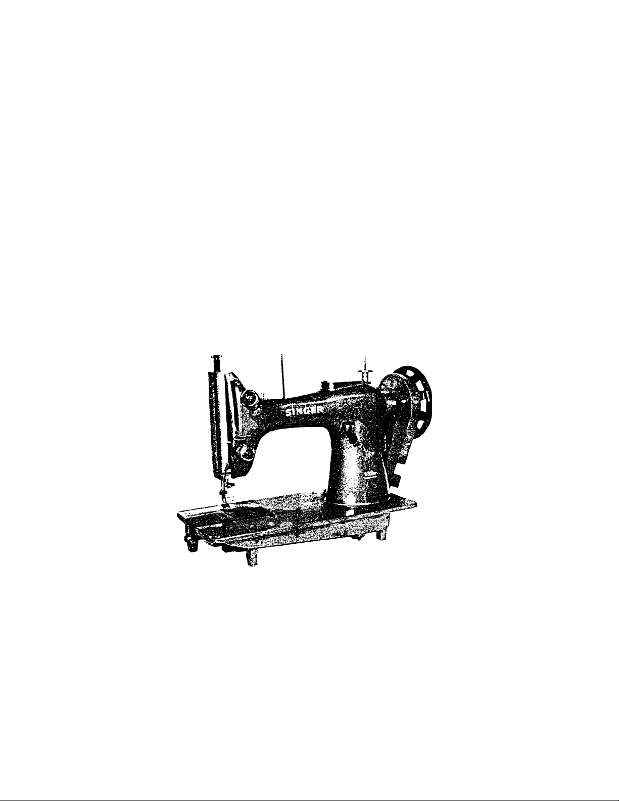
SINGER
OPERATOR'S GUIDE
MODEL 132B26
Page 2

4;
s
K
if
S;
i:
SPECIFICATIONS
SPEED:
ROTARY HOOK:
BOBBIN :
NEEDLE:
NUMBER OF NEEDLE
THREAD:
FEED MECHANISM:
STITCH LENGTH:
PRESSER BAR LIFT;
PRESSER FOOT:
WORKING SPACE:
132 B26
800 r.p.m.
ii32S
34.5(i X 15.6 mm
Cat. No. 4950 ^rlS—2
Two
Synthetic If 2-# 00
Drop feed
Maximum 8 mm
Maximum 10 mm
Flat presser foot &
roller presser foot
254 mm x 195 mm
Page 3
CONTENTS
I’lige
Setting Up the machine............................................................................................................. 2
Speed of the machine ............................................................................................................ 3
Oiling........................................................................................................................................... 4
Needle and thread....................................................................................................................5,6
Winding bobbins........................................................................................................................ 6
Inserting and removing the bobbin case and bobbin........................................................ 7
Threading the machine ............................................................................................................ 8
Preparing for sewing................................................................................................................. 8
Regulating the thread tension................................................................................................8,9
Adjusting the presser foot pressure..................................................................................... 9
Adjusting the stitch length....................................................................................................... 9
Bulge guide of sewing material ............................................................................................... 9
Gauge parts.............................................................................................................................. 10
One or three needle machine................................................................................................ 10
Piping or beading work .......................................................................................................... 10
Dummy-joint finish with knife
.............................................................................................
10
Two roller presser feet........................................................................................................... 11
Timing between the hook and needle.................................................................................. 11
Adjusting the height of the needle bar ............................................................................... 11
Adjusting the hook retainer bracket..................................................................................... 12
Adjusting the height of the feeder........................................................................................ 12
Adjusting the feed bar hinged stud....................................................................................... 12
Timing between needle and feeder........................................................................................ 13
Adjusting the up and down travel of the feeder................................................................. 13
Adjusting the height of the presser foot
...............................................................................
14
Adjusting the thread controller spring................................................................................. 14
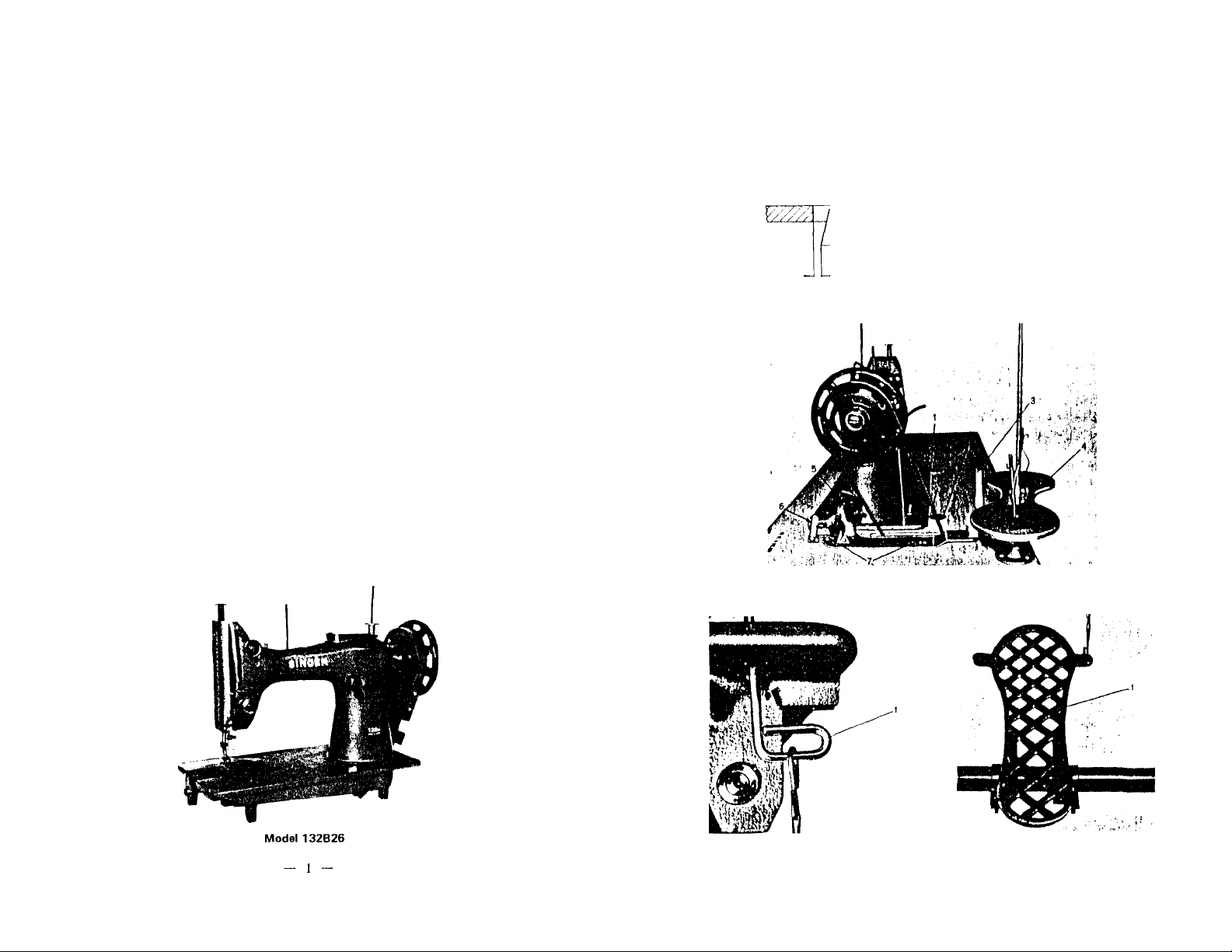
SETTING UP THE MACHINE
Carefnllv unpack the machine from the packing case and make sure that al
small parts and accessories are removed from packing material.
Fig. 1 To atfoch drip pan io Ihe table
Fig. 2 To Initall the machine on the table
Fig. 3 & 4 To ouemble the pedal
— 2
Page 4

Fig. 5 Th® proper angle of the pedal
OILING
Do not operate the machine, even if only for testing, unless it has been
properly oiled at every .spot requiring lubrication.
The arrows on the figures 7, 8, 9, 10 and 11 indicate these spots.
Oiling must be done at least twice daily when the machine is in continuous
operation to assure free running and durability of the operating parts.
SPEED OF THE MACHINE
The maximum speed for machines of class 132B26 is 800 stitches per minute.
Machines should be run slower than the maximum speed, until tJie parts which
are in movable contact have become glazed by their action upon each other.
— 3 —
Fig. 7
Fig. 9
Fig. 8
Fig. 10
— 4
Page 5

Fig. n
NEEDLE
The machine is set up to use Needle Cat. No. 4950 in si/e ranging lioni 18
to 29.
The thickness of tlie sewing thread, which must pass freely through the needle
eye, determines the size of the needle.
To insert the needle, turn the machine pulley toward you, until the needle
bar rise to its highest point, loosen the needle set screw (2) and put the needle
up into the needle bar as far as it will go, with the long groove of the needle,
or toward you. Then, tighten the needle set screw securely.
THREAD
Otdy left twist thread is to he used for
the needle, to test for twist, hold a length
of thread between thumbs and iiulex
fingers of your hands. Turn the thread
counterclockwise.
If it will twist tighter, it has a left .'twist.
If it unravels, it has a right twist.
The bobbin can be wound with either left or right twist thread.
WINDING BOBBINS (Figs. 2 and 15)
The bobbin winder is mounted on the table top with its pulley (5, Fig. 2)
in front of the driving belt so that the pulley will separate from the belt after
the bobbin has been wound with sufficient thread, push the bobbin on the
bobbin spindle (3 Fig. 15) as far as it will go.
Pass the thread from the thread stand downward through the eye (1, Fig. 1,5)
in the tension bracket.
Then, between and around the hack of the tension discs (2 Fig. 1,5) bring
the thread forward toward the bobbin and wind from below in clockwise direc
tion several times around the bobbin. Push bobbin winder lever (4, Fig. 15)
downward until the wheel (5) contacts the drive belt and start the machine.
After the bobbin is filled with thread, release will cause the wheel to disen
gage from the belt and winding will stop. Cut the thread and remove the
bobbin from the winder spindle.
The adjusting screw (A, Fig. 15) can be turned in or out to increase or
decrease the amount of the thread wound on the bobbin.
If the thread does not wind evenly on bobbins, loosen the screw (B, l ig 1.5)
and move the bracket to the right or left as may be required and tighten the screw.
— 5
Fig. 13
Fin. 15
Page 6

INSERTING AND REMOVING THE BOBBIN CASE AND BOBBIN
Turn the balance wheel until the needle is above the needle plate.
Push the retainer (1, Fig. 16) to the left like the figure 16, and remove the
bobbin case (2, Fig. 16).
Pull up the latch (1, Fig. 17) and lift the bobbin from the bobbin case.
To insert a full bobbin, raise the latch in center of the bobbin case, and
place the bobbin on the center post of the bobbin case.
Be sure that the thread draws out from the bobbin from left to right.
Pull the thread into the cut (4, Fig. 18) in the edge of the bobbin case, and
from you under the tension spring (5, Fig. 18). Then, pass its end from the
back through the hole (6, Fig. 18) in the bobbin case.
Finally, push down the latch to retain the bobbin in position.
Fig. 16
Fig. 17
from you
1 ,
leaving the end of the thread about 10 cm long.
PREPARING EOR SEWING
With the lelt hand hold the end
of the needle threarl, leaving it (piite
slack from the end to the needle.
Turn the hand pulley toward you
until the needle moves down and up
again to its highest position, thus
catching the under thread.
T'hen, pull the end of the needle
thread you are holding, then the
bobbin thread will be brought up
with it through the needle hole in
the needle plate.
THREADING THE MACHINE
Raise the needle bar to its highest
point, learl the thread from the hole
(I) through the thread guide (2), from
above between the retaining discs (,'i),
and from right to left around the ten
sion discs (4), over the spring (6), un
der the slack thread regulatrrr (6), up
through the guard (7), from right to
left through the hole in the take up
lever (8), down through the thread
guide (9) and the thread guide (10),
through the needle clamp hole (It),
then through the eye of the needle
— 7 —
Fig. 19
TENSION OF THE BOBBIN THREAD (Fig 18)
If it is necessary t(i alter
the tension on the bobbin
thread, slightly turn the screw
(7) to the right to increase it
or turn the screw to the left
to decrease it.
Fig. 23
I" Perfect stitching.
- Tight tension of needle thread
Loose tension of needle thread.
Fig. 24
— 8
Page 7

REGULATING THE THREAD TENSION
The thread tensions of upper thread
(a) and lower thread (b) should he
equal
1. Correct tension
2. Tight tension of needle thread
Fig. 26
3. Tight tension of bobbin thread
ADJUSTING THE TENSION OF THE UPPER THREAD
The serrated nut (fi) controls the tension of two
upper threads. To increase the tension, turn the
nut to right, or to left to decrease it.
ADJUSTING THE TENSION OF THE LOWER THREAD
Fig. 27
See the instructions for SK machines.
ADJUSTING THE PRESSER FOOT PRESSURE (Fig, 7)
The pressure of the presser foot is regulated by the screw (1).
To incrca.se the pressure, turn it to the right and to the left to decrease the pressure.
GAUGE PARTS
There are three kinds of gauge parts (needle clarttps) as 3.5 mm 4.8 mm and
7.5 mm, wliich can be changed according to your purpose, replace it to the re-
(luired size.
ONE OR THREE NEEDLE MACHINE (SKM only)
One needle machine is used for decorative coarse straight stitching.
On three needle machine, either the right or left side (two needles) make
moccasin stitch and the other needle makes decorative coarse stitching.
I hree needle machine can also be used for only the decorative coarse stitciiing
I hese stitchings can be made by replacing the re.spective presser foot, needle
clamp, needle plate, and feeder.
Fig. 29
Fig. 30
PIPING OR BEADING
Piping requires a special needle plate witli a
hole for die cord.
ADJUSTING THE STITCH LENGTH (Fig. 7)
Turn the balance wheel toward you, at the same time pressing on the feed
regulating lever (2) until it snaps into the feed driving mechanism.
Continue the pressure on the lever and turn the balance wheel either to or from
you until the travel of the feed is such as to give the required length of stitch.
THE BULGE GUIDE OF SEWING MATERIAL
Normally, edge of the guide (1)
comes to the center of the needle
plate.
To adjust this, loosen the set
screw (2) and move the guide to
ward the arrow direction.
The shape of the guide can be
varied according to the sewing
Fig. 28
purpose.
Fig. 31
DUMMY-JOINT FINISH WITH KNIFE
A knife fitted on the pres,ser foot makes dummy-joint finish on the shoe up
pers, For this work, knife and special presser foot with groove are required.
TWO ROLLER PRESSERS (SKM only)
Tie roller pressers employ ball bearings to airl
in curve stitching.
Fig. 32
10
Page 8

THE TIMING BETWEEN HOOK AND NEEDLE
Loosen the hook set screws, turn the halaiice wheel toward you until the
needle bar raises to .'1.8 iiiiii from its lowest position.
Bring the hook point (I, I'ig. .’!(i) to the renter between two needles (2) and
(.'!), then tighten the hook screws, at the same time, set the clearance between
the needle and hook point 0.1mm to 0.2 mm.
ASSEMBLING THE HOOK RETAINER BRACKET
This must be done after adjusting
the clearance between the needle and
hook.
Let the retaining spring (2) contact
sufliciently, but not to bend, with the
hook (3) without any clearance, then
tighten the screw (4) securely.
Excess contact between the two
makes unnecessary wear and noise.
Fig. 39
ADJUSTING THE HEIGHT OF THE FEEDER
Adjust the feed motion to the maximum and turn the balance wheel to raise
the feed dog to its highest position.
Loosen tite screws (I,
Fig. 41), adjust the height
of the feeder by raising or
lowering it to 1.4 mm
from the surface of the
needle plate to the feeder.
Tlicn tighten the said
screws securely.
Fig. 38
ADIUSTING THE HEIGHT OF THE NEEDLE BAR
This shotdd be made after the timing between the
needle and hook has been determined.
Turn the balance wheel toward you so as to fit
the center of the left needle to the hook point.
Loosen the screws (1, Fig. flH), adjust the needle
bar up or down so that the up|ier end of the needle
eye comes to 3.5 mm down from the book point,
at the same time, the two needles must be parallel.
Then, tighten the screw (1, Fig. .'18).
11
Fig. 41
ADIUSTING THE FEED BAR HINGED STUD
jn When the feed dog is at its highest position, if it
Lw j,; parallel with the surface of the needle plate,
loosen the stud screws (I ) and turn the stud (21 to
get it parallel, then tighten the screws.
Fig. 42
12
Page 9

TIMING BETWEEN NEEDLE AND FEEDER
The correct timing is as follows:
Adjust the feeding motion to the maximum and turn the balance wheel to
ward you, after the feed dog has finished its feeding motion and when teeth
of the feeder become equal height to the surface of the needle plate, the needle
reaches to the needle plate.
To adjust this, pull open the top cover (I), loosen three screws (3) out of
five on the feed eccentric adjusting flange coupling (2) and move the feed ec
centric adjusting flange (4) for the adjustment.
Fig. 43 Fig. 44
ADJUSTING THE UP AND DOWN TRAVEL OF THE FEEDER
The adjustment of the up and down travel of the feeder against its hack and
forth travel is made so that the teeth of the feeder rise to the highest point
at the middle position, when feeding travel is the largest.
Loosen two screws (5) and adjust it against the main shaft by moving the
feed lifting cam (6).
To make its up and down travel faster, turn the feed lifting cam toward
driving direction and to make it slower, turn the cam toward opposite direction.
Be sure to tighten screw pushing the screw against the rod (7) not to make
any clearance axialy.
ADJUSTING THE HEIGHT OF THE PRESSER FOOT
Raise the presser bar lifter (1) and so adjust the
measurement to 10 mm between the bottoiii ol
the presser foot (2) and the surface of the needle
plate (3).
To adjust this, loosen the screw (4), fit the needle
hole of the presser foot to the needle by moving the
presser bar (5) up or down, then tigliten tire screw.
Fig. 46
— 13
ADJUSTING THE THREAD CONTROLLER SPRING
(Fig, 27)
Normally, the thread controller spring (4) should hold slack of the upper
thread until the needle reaches to the goods, and it should pause.
To adjust this, loosen the screw (5) and adjust it by turning the thread take
up spring regulator (6).
To strengthen the tension of the controller spring, loosen slightly the tension
.screw stud (7) with a screw driver and turn the serrated nut to the right, to
lighten the tension, turn to the left. Then, tighten the tension screw stud.
- 14 -
 Loading...