

Page 1

SINGER
121W and 122W
Page 2
OKM 1223\v
;f;virei)
EPTEMBEn,
PRICE LIST
INDEX
AccKssoHtKs
BoiiMN Winder ...........................
Folder ............................................
Knee Lii ter
Lap Seam Edge Guide ....
“ “ Fei.i.eh
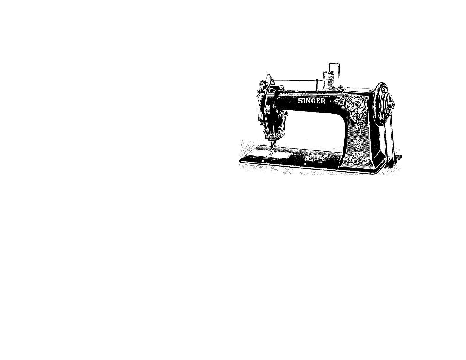
Maciiine No. 121w1
Numeuioai. List of Parts
Orsolete Parts ..........................
PuESSER Feet ...........................................
Roller Wei.t Gadoe
Throat Plates ............................
................................
.................................
.........................
.......................
121w2
..............
121w3
..............
12lw4 ...............
122wl ...............
122w2
..............
................
■A(!E
54
54
HI
5!)
59
29
37
4fi
55
15
22
63
61
57
60
58
OF
PARTS
7
MACHINES
OF
1223W-2
CLASSES 121w and 122w
THE SINGER MANUFACTURING COMPANY
Page 3
Instructions for Ordering
In ordering from this list, use ONLY the PART number In
the FIRST column.
The number stamped on a Sewing Machine Part is the
number of the Single Part only, exce])t wlien tlie jiart inchuies Set
Screws, Clamping Scia'ws, St\ula and Itoliers S]iun on, Small
Wires riveted, or Parts soldeied tngetlier, ('Ic., which It Is
necessary to furnish in combination.
Every combination of parts sent out has its specific number
which, although not stamped on Parts (exce))t in above cases)
must be used when ordering the comldnation.
Each number always indicates the SAME PART in whatever
list it appears, or for wliatever Machine.
The letters after some of the numliers indicate the style of
finish only, as follows:
A. Hardened, Polished and Plated.
! B. Polished and Plated.
C. Hardened only.
D. Polished only.
E. Soft, not polished.
F. Hardened and Polished.
H. Blued.
These letters MUST BE USED wlien they appear in the list
and AFTER the number, as in the list.
In this series
200001 to 201500 are Screw Numbers.
201501 to 201800 are Nut Numbers.
201801 to 202000 are Roller Numbers.
202001 and upward are numbers of Machine Parts.
The figures in the second column refer only to the plate
in which the illustration of the part is shown and are NOT TO
BE USED in ordering.
Two or more numbers over a cut indicate that the difference
between such parts is not visible in an illustration.
Parts marked with an asterisk (♦) are furnished only when
repairs are made at the factory.
LIST OF PARTS COMPLETE
FOR
MACHINE No. 121wl
NEEDLE FEED. ALTERNATING PRESSERS.
For Sewing Rough, Uneven or Sticky Goods.
No. Plate Name Each
*213451
202247 11055 “ Cap
20027SII 12.111 “ “ Screw
202248 11701
204215 11701 “ Position Pin (2)
200004r: 110(11 “ Screw (1)
202005 11701 “ “ Washer (1) ...................................... 01
21.3401 11183 “ Shaft ...................................................... 1 75
20224.3 11055 “ “ Bushing (back) wltli
202244
200338c 11701 Arm Sliaft Bushing (back) Set
213452 11055 Arm Shaft Bushing (front) with
------
Arm..................................................................... ? —
............................................
......................
202244
...........................................................
-----
Arm Sliaft Bnsliing (back) Oil
Packing (wick)
Screw
.............................................................
202260
........................................................
........................................
Washer
..............................
...................................
........................................
...............................................
05
25
0.5
02
08
75
02
04
.15
Page 4

8
Parts for Machine No. 121w1
Parts for Machine No. 121w1
!)
No.
202260
Plate Name
------
Arm Shaft Bushing
(front)
Paching (wicti) . . ,
200352c 11701 Arm Shaft Bushing
(front)
Screw ........................................
2134,53 11055 Arm Sliaft Connection Belt
213454 11055 “ “ “ " Bulley
with 200363c, 200396c and two
213455 .....................................................
200396c 11701 Arm Shaft Connection Belt Pulley
Position Screw .........................................
200363c 11701 Arm Shaft Connection Belt Pulley
Set Screw .................................................
213455 11063 Arm Shaft Connection Belt Pulley
Spring Flange
..........................................
213492 11055 Arm Shaft Counter Balance with
200347c ...................................................
200347c 11063 Arm Shaft Counter Balance Set
Screw .......................................................
213471 11183 Balance Wheel (bolt groove 23 in.
dJam.) with two 200.3.3.5c
.....................
200062ц 12311 Balance Wheel Adjusting Screw. .
200335c 12311 “ " Set Screw
..........................
*213468 — Bed ........................................................................
202258 12153 “ Hinge Connection (2)
200570k 12311 “ “ “ Screw' (4)
............................
________
213477 11055 “ Slide (haclO with 213478 and
213479
213476 11055 Bed Slide (front) with 213478 and
213479
213478
213479
213783
*213444
203648
♦202056
213932
203474
213446
213447
200099H
213445
200984c
11063 Bed Slide Friction Slide...................................
11063 “ “ “ “ Spring ...
11064 Bobbin
.........................................................
------- “ Case ....................................................
11703 “ “ I.,atch
11703 “ “ “ Pin
11703 “ “ “ Plunger
11703 “ “ “ Spring
11064 " “ Lever
.......................................
..........................
.........................
...........................
..................................
11064 “ “ “ Arm with 200099n
11703 “ “ “ “ Pinch Screw
11064 “ “ Tension Spring
..........................
11703 " " “ “ Regulat
ing Screw
200594c
213689
11703 Bobbin Case Tension Spring Screw
11064 Bobbin Case complete. Nos. 200594c,
20OS84r, 202056, 203474, 203648,
221580
213444, 213445 and 213932
— Face Plate with 200368тг, 200739P,
...................
202087, 202090, 213691 and four
> 200397H
..................................................
Oil
Set
Each
% 01
1 00
1 25
1 00
60
10
02
08
10
10
01
1 00
30
02
10
04
02
1 00
1 50
08
05
60
03
03
03
20
25
03
07
04
No.
200053c
200739k
221581
213464
213692
201827
Plate
12311
11063
11183
1106.3
11066
1106.3
201821
200818c
201522k
200035k
213465
213466
213467
200101n
213463
11066
11701
11066
11066
11066
11066
11066
11066
20()094f 11701 F<
213460 11702 F(
221569
213711
213639
200380c
213461
213494
213696
200095П
213496
201183П
200681c
*221550
221551
11701
11078
12319
11067
11067
11067
11067
11067
1106,3
11067
________
11703
221554
Name
Face Plate Screw (2) ....................................
“ “ Thread G\iide Screw . .
Face Plate complete, Nos. 200577n
202088, 204272, 204280, 210957
2109.58, 210992, 21099.3, 21.3.500
213690, 221580 and two 200309k
Feed (lam
.....................................................
“ Position Pin (2)
.............................
“ Roller ..........................................
“ “ 201827 w'ith 200818c
“ “ Screw Stud
......................
“ •' “ “ Nut..
“ Screw ..........................................
(hjiincctiou .......................................
“ Link ....................................
“ “ Lever
" Stop Screw
.......................
.........................
Eccentric Connection witli
200094k ...................................................
e,(l Eccentric Connection Pincli
Screw .......................................................
ed and Needle Carrying Frame
with 213711
.......................................
Feed and Needle Carrying Frame
213160 W'ith 200101r>, 201522k,
201821, 213461, 213463 to 21.3167,
213173 to 213475, 213481, 213483,
21.3185 to 213488, 213673 and tw'o
213184 .....................................................
Feed and Net'dle Carrying Frame
Bushing ....................................................
Feed and Neodlo Carrying Frame
Collar witli 200.'l8nc
...............................
Feed and Needle Carrying Frame
Collar Set Screw.......................................
Feed and Needle Carrying Frame
Link ..........................................................
Feed Regulating Lever .................................
.• “ “ F I- i e. t i 0 n
Washer .....................................................
Feed Regulating Lever Screw ....
“ “ “ Segment....
“ “ “ Screw................................................
•< “ “ Stop Screw'
Hook (.sew'ing) ............................................
221550 with 200088k, 213438
and 213644
Hook and Bobbin Case complete,
—
Nos. 213689 and 221551
..............................................
......
..................
1
Each
$ 04
08
! 25
75
02
12
30
15
03
05
40
50
50
04
1 00
02
50
15 75
10
15
02
75
60
10
04
25
04
04
'
5 00
6 00
Page 5

К)
Parta for Machine No. 121w1
Parts for Machine No. 121w) 1 1
No. Plate Name
213440 11064 Hook Bushing (lower)
213439 11064 “ “ (upper)
200378c 12311
213441 11064
200383c; 12311
213493 11707
213469 11702
213 47 0
200027k 11703 Hook Driving Shaft Bearing Bush
11064 Hook Driving Sliaft Bearing Bush
Driving Gear with two 200383c
“ “ Set Screw
“ Shaft
“ " Bearing with
200027k ........................................................
ing
....................‘......................................
.....................................
...................................
“ Set Screw
................................
........................................
ing Clamp Screw .....................................
200019k 11064 Hook Driving Shaft Bearing Screw
213 44 3
200027k
202574
200380c
11064
11703
11703
12319
(2) .........................................
Screw-
look Dr
200380c;
iook Dr
Screw .
221576
11069
Beit Pulley with 202324 and two
201421c
201421c
202 32 4
221552
221553
200397c
*213438
*213644
200088k
213442
200019k
202622
22155.5
11063
11063
11703
117 03
12349
-
-----------
—
11064
11069
11064
11703
11704
200378c;..............................
...................
Belt Pulley Set Screw ....
'ook Driving Shaft Conn
Belt Pulley Spring Flange
Ke,v
............
Sot Screw
Gib
“ Hinge rill
“ Screw
......................................
...........................................
Saddle with 200027k and two
Wa.sher (2) ...
213440, 213442, 213446, 213447 and
202445
213871
11707
—
221552 to 221554
202446 .....................................................
Knee Lifter Connection Lever
...................................
202445 with 200224ir, 200262n,
200224II
213870
11701 ]
Knee Ijitter Connection Lever Hinge
Screw
.............................................................
11707 Knee Lifter Connection Lever Lilt
ing Rod with 202302
213869 and 21.3870
......................................
.....................................
...................
Clamp
11 00
Each
? 25
1 OC
1 00
02
2 5 0
07
55
12
08
1 00
15
02
75
04
08
10
02
06
01
No. Plate Name Each
202302 11063 Knee iafter Connection Lever Lift
ing Rod Cotter Pin ................................... $ 01
....
20
02
02
25
202446 11701 Knee Lifter Connection Lever Pin 03
213869 11707 “ “ Lifting Lever
200262II 11701 “ “ “ “ Hinge Screw 10
213480 11185 Lifting i’resser Bar witli 200074k.. 85
213481 11070 “ “ “ (icillar with
35
26
04
06
25
04
200386c 11701 Lifting Pressor Bar Collar Set Screw 02
200572k 11070 " “ “ “ Slide Ad
2004901! 11070 Lifting Presaer Bar Sleeve Scrc'W
213482 11070 Lifting Prosser Bar Spring
2006351! 11070 “
200613k 11701 Lifting Pre.sser Bar Spring Pollowc-r
21 4057
------
200572k and two 2003S6c;...................... 1 00
justing Screw 04
and Nnt ........................................................... 35
........................
Screw
.............................................................
Follower
Screw Position Screw-.................................... 03
Lifting Presser Bar Vilu’ating Lever 1 10
.....
10
25
213483 11070
214057 with 200230k and 201525k 1 25
200230k 11070 Lifting Prc;.s.ser Bar Vilcrating Lever
Hinge Screw ................................................... 10
201525E 11701 IJfting Presser Bar Vil)i-ating Lever
Hinge Screw Nnt
...........................................
03
213485 11071 Lifting Presaer Bar Vilirating Lever
Rocker Arm ............................................. 1 00
213486 11071 Lifting Presaer Bar Vilirating Lever
Rocker Arm Link ........................................... 75
213484 11071 Lifting Presser Bar Vilirating Lever
Slide Block
....................................................
25
229755 11080 Lifting Pressor Foot ...................................... 1 00
2fl0074K 11701 “ “ Screw-
............
03
213473 11185 Needle Bar (hollow-) with 200125k 1 00
213474 11071 “ “ Collar wilii 200049k and
200.572k-........................................................ 50
200049k 11071 Needle Bar Collar Set Screw
....................
03
200572k 11070 “ “ “ Slide Adjusting
Screw
.............................................................
213475 11071 Needle Bar Connecting Link
2001251- 11701 “ Set Screw-
...............................................
............
04
75
02
202554 11701 Presser Bar Lifter .......................................... 25
20002611 11071 “ “ “ Hinge Screw .. 04
213490 11071 “ " “ Shoe and Ten
sion Release Stud............................................ 40
202068 12153 Spool Holder Base ................................. 15
200575II 12311 “ “ “ Screw
204296 12453 “ “ Wire
..............................................
200079U 12311 “ “ “ Hinge Screw
...........................
-----------
02
05
10
Page 6

12
Parts for Machine No. 121w1
Parts for Machine No. 121w1 LI
No.
204297
21367.3
200430c
200383c
200335c
213498
221572
213697
204264
200042).201816
213499
202402
202090
213500
200309);
202075
202407
200632)!
200397)1
201572)!
204271
204272
204274
Plate
12153
11702
12311
12311
12311
11705
—
11071
11705
12311
11705
11705
12349
12349
11072
12349
12349
12349
12349
12349
12349
12349
12349
12349
2005771Г 12311
202098
204275
202084
200300Г
204276
204333
200581H
202087
202088
2003G8ir
12349
12349
12349
12349
12349
12319
12349
12349
12349
12349
204925 1170,3
205987 12349
Name
Spool Holder coin])lote, Nor.
2(KU)7!1h, 2(»2068 and 2P42fl6
............
Take-tip Cam with 20033r)C, 200383('
and 200430c
Take-iip Cam Position Screw
............................................
.....................
“ “ “ “ Check
Screw .......................................................
Take-up Cam Set Screw...............................
“ Never ................................................
“ “ 213408 with 2i:!(;i»7
“ “ Bearing witli 204204..
“ “ “ I'ositioii Pin . .
“ “ “ Screw
" “ Holier
......................
...................................
Take-up Lever complete, Nos,
200042F, 201816 and 221572
.................
Tension Disc ................................................
“ “ Position Pin
.......................
“ Release Lever .....................................
“ “ “ Screw
......................
“ “ Plunger .................................
“ Spring
.................................................
“ Stud
....................................................
“ “ Set Screw
.................................
“ Thumb Nut .........................................
“ Washer.................................................
Ten.sion complete, Nos. 2006,32n,
201,572n, 202075, 202107, 204271
and tw'o 202402
Thread Controller Plate
......................................
...............................
“ Screw . ,. ,
“ Roller
...............................
“ " Guard................
“ “ Waslier
“ “ Screw
“ Spring
“ “ Guard
..................
..............................
.........
“ " “ Screw..
“ “ Stop
..................
“ "St n d w i t li
204925
Thread Controller Spring Stud Set
Screw .......................................................
Thread Controller Spring Stud
Washer...........................................................
Thread Controller complete. Nos.
200300c, 20058111, 202098, 204274,
204275 and 204333
.................................
Each
$ 25
2 25
08
02
04
1 00
1 15
15
01
05
12
1 25
05
01
10
04
03
05
20
02
04
05
50
12
02
05
10
01
04
03
08
02
03
10
02
01
42
No. Plate Name Each
204280 12349 Thread Controller and Siiring com
plete, Nos. 204276 and 205987 . . . | 45
213448 11072 Thread Draw
....................................................
213614 11072 “ " Driving Fork Lover
rvitli 20038911 ......................................... 60
213501 11072 Thread Draw Driving Fork Lover
Eccentric with 200366n
................................
200366ir 12349 Thread Drarv Driving Fork Lever
Eccentric Set Screw
.......................................
200389И 11701 Thread Draw Driving Fork Lever
Set Screw
213450 11072 Thread Draw Driving Sliaft
.......................................................
..........................
213613 11071 " " " " Collar
with 200389И ................................................. 10
200389И 11701 Tliread Draw Driving Sliaft Collar
Set Screw
.......................................................
213449 11073 Tliread Draw Lever witii two each
200355II and 200397n
....................................
200355ц 12319 Thread Draw Lover Adjusting
Screiv
.............................................................
200397II 12349 Thread Draw Lever S(d Screw' .... 02
20039711 12349 “ " Set Screw .............................. 02
202412 11703 “ Guide 06
21 3489 11073 “ “ 10
200389c 11701 “ " Set Screw ................................... 02
202482 12319 “ Retainer Disc ........................................ 02
213691 1 1072 “ “ Guide IVire
..............................
200397и 12349 “ “ “ “ Set Screw 02
210993 1 1063 “ " Sleeve .............................. 05
202483. 12319 " " Spring (brass)
........................
210992 11063 “ “ " ........................ 01
200631 c 11072 “ “ Stud............................................ 10
210957 11063 “ " "
21095S 11063 “ “ “ Collar
2015711) L1072 “ “ “ Nut
.................................
............................
.....................
0.3
12
200397)) 12349 “ “ “ Set Screw ....................... 02
213690 11072 Thread Retainer cmnpteto, Nos.
300631);, 201574)), 202483 and two
202482
.....................................................
212841 11074 Throat Plate, 53 needle l)olo, for
needle sizes 10 to 20................................. SO
200577)1 12311 TI)roat Plate Screw (2) ............................. 02
213487 11185 Vibrating Presser Bar rvith 200389c 60
213488 11073 “ “ “ Collar with
200.386c and 200572)'
..........................
200386c 11701 Vibrating Presser Bar Collar Set
Screw
.............................................................
200572F 11070 ATbrating Presser Bar Collar Slide
Adjusting Screw ............................................. 04
15
7.5
02
02
15
02
75
03
05
01
08
20
40
02
Page 7

14 Parts for Machine No. 121w1
No. Plate Name Each
213484 11071 Vibrating Presser Bar Collar Slide
Block
213489 11073 Vibrating PrcsRcr Bar Thread Guide 10
200389c 11701 “
229751 11079 Vibrating Presser Foot, 46 needle
200941c 11701 Vibrating Presser Foot Pinch Screw 03
........................................................
........................
Set Screw ....................................................... 02
hole, with 200941c................................... 1 25
.
$ 25
LIST OF PARTS COMPLETE
FOR
MACHINE No. 121w2
NEEDLE FEED. ALTERNATING PRESSERS.
1
1
i 200338c
For Sewing and
No.
♦213451
202247
20027811
202248
204235
200004i:
202005
213491
202243
202244
213452 11055
j 202260
200352c
213453
213454
20039GC 11701 Arm Shaft Connection Belt Pulley
200363c 11701 Arm Shaft Connection Belt Pulley
213455 11063 Arm Shaft Connection Belt Pulley
213492 11055 Arm Shalt Counter Balance with
200347c 11063 Arm Shaft Counter Balance Set
213471 11183 Balance Wheel (belt groove 23 in.
Binding Mackintoshes,
Plate
11055
12311
11701
11701
11063
11701
11183
11055
—
Arm Shaft Bushing
Arm Shaft Bushing
11701
Arm Shaft Bushing
---
-
Arm Shaft Bushing
Arm Shaft Bushing
11701
Arm Shaft Connection Belt ..
11055
11055
etc.
Name
“ Cap..............................
“ “ Screw
“ “ “ Washer
“ Po.sition Pin (2)
“ Screw (3)
“ “ Washer (3)
“ Shaft
“ “ Bushing
202244
Packing (wick) . ..
Screw
202260
Packing (wick) . . .
Screw
21.3455
......................
..................................
...................
...........................
.........................
...........................
.........................
...........................
with 200363c, 200396c and
........................
Po.sition Screw
Set Screw .................................................
Spring Flange............................................
200347c
Screw
diam.) with two 200335c.......................... 1 00
........................................
...................................................
.......................................................
Rubber
(back)
(back) Oil
(back) Set
(front)
(front)
(front)
Overcoats,
___
35
___
05
___
05
___
02
___
08
___
01
with
___
04
with
___
35
Oil
......... 01
Set
.........
03
......... 1 00
Pulley
tAVO
.........
1 25
Each
.... 1 75
75
02
03
03
20
25
03
Page 8

10
Parts for Machine No. 121w2
Parts for Machine No. 121w2
17
No.
200062И
200335c 12311
♦213468
202258 12153
200570k 12311
213477
Plate
12311
---
---
11055
Name
Balance Wheel Adjusting Screw . .
“ “ Set Screw
Bed
..............................................................
“ Hinge Connection (2)
.........................................
............................
“ “ ■' Screw (4) ....
“ Slide (hack) wdth 213478 and
213479 .....................................................
213476
11055
Bed Slide (front) with 213478 and
213479 .....................................................
213478
21347!) 11063
213783
♦213444
203648
♦202056
213932 11703
203474 11703
213446
213447
200099П
213445 11064
200984c
200594c
213689
11063
Bed Slide Friclion Slide
11064 Bohldn
“ " " “ Spring
“ Case
11703
11703
.
.......................I’in ..................................
----------------------------------
.........................................................
....................................................
“ Lai eh
“ •' “ Plunger ..........................................
“ “ “ Spring ............................................
11064
11064
11703
“ “ Lever ................................................100
“ ■■ “ Arm with 20009911 30
“ ' “ “ Pincli Screw 02
“ “ Tension Spring..................................
11703
11703
11064
“ “ “ " Régulât-
ing Screw
..................................................
Bobbin Case Tension Spring Screw
Bobbin Case complete. Nos. 200594c,
..............................
.......................................
200984c, 202056, 203474, 203648,
221580
213444, 213445 and 213932
—
Face Plate wllh 2n(l36Sii, 200739i',
...................
202087, 202090, 213691 and tour
20039711 .................................................
200053c 12311
200739k 11063
221581
Face Plaie Screw (2) ....................................
“ “ Thread Guide Screw . .
11183
Face Plate complete. Nos. 200577fi,
202088, 204272, 2042S0, 210957,
210958, 210992, 210993, 213500,
213690, 221580 and two 200309k. .
213464 11063
213692 11066
201827 11063
201821
200818c 11066
201522k 11701
200035k
Feed Cam .....................................................
“ “ Position Pin (2) ...................................
---
“ “ Roller
---
“ “ “ 201827 with 200818c 30
“ “ “ Screw Stud
.................................................
.......................................
......................... “ “ Nut . ,
11066
“ “ Screw..................................................
213465 11066 “ Couiiectiou ............................................
213466 11066
213467
11066
200101D 11066
213463
11066 “ Eccentric Connection with
“ “ Link ....................................................
“ “ “ Lever
...............................................
“ “ Stop Screw ......................................... 04
200094k ........................................................ 1 00
Each
Î
1
1
3 25
No.
07
04
__
08
05
200094k
213460
221569
60
60
10
02
08
10
10
01
213711
213639
200380c
213461
213494
213507
10
04
02
213506
213702
200П951!
213496
00
2011831)
200681c
Plate
4701
! 1702
—
1701
11078
2319
' 1067
11067
' 1073
11073
4073
4 067
4067
4063
1 1067
Screw
with 312711
Feed and Needle Cai-rying Frame
21.2460 with 200101n, 201522i:,
201821, 213461, 213463 to 213467,
213473 to 213475, 213481, 213483,
213485 to 213488, 213673 and two
213484
Bushinp;
Link
Pin (2)
Washer
Зсгелу
Name
.............................................
.....................................................
.......................
eed and Needle Cai
Collar with 200380c
'eed and Needle Cai
Collar Set Screw .
Connection
er Screw ....
Segment
ever Segment
Stop Screw
50
04
08
213503
20П2171Г
213505
200781)1
♦221550
221551
75
02
221554
12
213440
15
03
05
40
50
50
213439
200378c
213441
200383c
213493
213469
213470
11077
11073
11073
11073
—
11703
—
4064
11064
12311
11064
12311
11707
11702
L1064
Hinge Screw
Spring ....
Screw
...................
Hook (sewingl .
“ 221550 w'ith 2000S8F, 213438
and 213644
..............................................
Hook and Bobbin Case complete.
Nos, 21368!) and 221551
Hook Bushing (lower)
........................
.......................................
(upper) . .
Set Screw
Driving Gear with two 200383c 1 00
“ “ Set Screw
“ Shaft
.........................................
...................
“ “ Bearing with
200027k
Ing
Each
$ 02
1 50
15 75
10
15
02
75
60
20
05
01
04
25
04
04
40
15
25
" Stop
08
5 00
6 00
25
........... 25
......... 02
02
1 00
35
25
Page 9

18
Parts for Machine No. 121w2
Parts for Machine No. 121w2
19
No.
200027e
Plate
11703
Name
Hook Driving Shaft Bearing Bush-
ing Clamp Screw .....................................
200019e
11064
Hook Driving Shaft liearing Screw
(2) ............................................................
213443
200027e
11064
Hook Driving Shaft Busliing........................
11703
“ “ “ “ Clamp
Screw .......................................................
202574
11703
Hook Driving Shaft Collar with
200380c ...................................................
200380o
12319
Hook Driving Shaft Collar Sot
Screw .......................................................
221576 11069
Hook Driving Shaft Connection Belt
Pulley with 202324 and two
201421c ...................................................
201421c 11063
202324
221552
221553 11703
200397c
'213438
*213644
200088P
213442
Hook Driving Shaft Connection Belt
Pulley Set Screw
.....................................
11063 Hook Driving Shaft Connection Belt
Pulley Spring Flange
...............................
11703 Hook Gear with 200397c .............................
“ " Kov
....................................................
12349 “ “ Set Screw
------
—
11064
11069
“ Gib ........................................................
“ ‘‘ Hinge Pin
“ “ Screw..................................................
“ Saddle with 200027e and two
...........................................
...........................................
200378c ................................................... 2
200019e
202622
221555
11064
Hook Saddle Screw (2)
...............................
11703 " “ “ Waslier (2) . .
11704 Hook Saddle complete. Nos 213439,
213440, 213442, 213446, 213447 and
221552 to 221554
...................................
202445 11707 Knee Litter Connection Lever with
202446 ..................................................... 07
221567
—
Knee Lifter Connection Lever
202445 with 200217ir, 200224ii,
213869 and 213870 .................................
200в24н 11701 Knee Lifter Connection Lever
Hinge Screw ............................................ 12
213870
11707
Knee Lifter Connection Lever Lift-
ing Rod with 202302 ...........................
202302
202446 11701
213869
11707
213480
213481 11070
200386c
Knee Litter Connection Lever Lift-
11063
ing Rod Cotter Pin
Knee Lifter Connection Lever Pin
“ “ Lifting Lever ...................................... 20
Lifting Presser Bar with 200074e ,.
11185
200572e and two 200386c
Lifting Presser Bar Collar Set
11701
..................................
“ “ “ Collar with
......................
Screw .......................................................
Each
No.
200572F 11070
04 Ad lusting Screw
$
200490b 11070
06
25
213482 11070
200635b 11070
Plate
Llftii g l’resser Bar Collar Slide
Lifting Presser Bar Sleeve Screw
ап(1 Nut ...................................................
Lifting Presser Bar Spring
“ “ “ “ Follower
04
200613F 11701
Lifting Presser Bar Spring Follower
15 Sci ew Position Screw
—
02
213483
214057
Lifting Presser Bar Vii>rating Lover
11070
“
21-1057 with 200230e and 201525e
Lifting Presser Bar Vibrating Lover
200230e
11070
75 Hinge Screw
Lifting Presser Bar Vil)rating Lever
201525e
11701
04 Hinge Screw Nut
Lifting Pressor Bar Vibrating Lever
Ro ‘kcr Arm
Lifting Presser Bar Vilirating Lever
1 00
08
213485 11071
213486 11071
10
02
—
—
02
50
06
01
11 00
60
08
01
03
85
213484 П071
229755
200074e 11701
213473 Ш85
213474 11071
200049e 11071
200572e 11070
213475 11071
200125e 11701
202554 11701
200026D 11071
213490
202068
200575II 12311
204206 12152
200079II 12311
204297 12153
213673
200430c
200383c 12311
Lifting Pressor Bar Vilirating Lever
Slide Block
Lifting Presser Foot
И080
“ “ “ Screw
Needle Bar (hollow) with 200125e. .
“ “ Collar with 200049e and
20П572Е .......................................................
Neeiile Bar Collar Set Screw........................
“ “ “ Slide Adjusting
Sc ew
.......................................................
Needle Bar Connecting Link
" Set Screw
Pres :er Bar Litter
“ “ “ Hinge Screw ..
11071
“ “ “ Slice and Ten-
si( 11 Release Stud ....................................
12153
Spool Holder Base
“ “ “ Screw
" “ Wire
.................................................
“ “ “ Hinge Screw ....
Spool Holder complete. Nos.
2 0 ПП7 ЯП, 202068 and 204296
Talii -up Cam with 200335c, 200383c
11702
ami 200430c
12311
Talc -up Cam Position Screw
' “ “ “ Check
Sinew .......................................................
1 00
02
200335c
213498
221572
12311 Talo -np Cam Set Screw...............................
11705
—
' Lever
‘ ‘‘ 213498 with 213697 . .
Name
.....................................
...........................
..............................
.............................................
.....................................
............................................
..............................................
......................................
............................................
........................
............................................
........................................
........................................
............................................
...............
............................................
.......................
................................................
Each
?
04
35
10
25
03
1 10
25
1
1
1
1
2
1
1
10
03
00
75
25
00
03
00
50
03
04
75
02
25
04
40
15
05
10
02
25
25
08
02
04
00
15
Page 10

Parts for Machine No. 121w2 19
Parts for Machine No. 121 v2
21
No.
Píate
200572F 11070
200490b
11070
213482 11070
200635b 11070
2006131Í- 11701
214057
213483
200230if
201525e
213485
—
11070
11070
11701
11071
213486 11071
213484 11071
229755
11080
200074 [i- 11701
213473 11185
213474
200049e
11071
11071
200572e 11070
213475 11071
200125e
11701
202554 11701
200026o 11071
213490 11071
202068
12153
20057511 12311
204296 12153
200079II 12311
204297 12153
213673 11702
200430o
12311
200383o 12311
200335o 12311
213498 11705
221572
Name
Lifting Presser Bar Collar Slide
Adjusting Screw
......................................
Lifting Presser Bar Sleeve Screw
and Nut ....................................................
Lifting Pressor Bar Spring ...........................
“ “ “ “ Follower
Screw .......................................................
Lifting Presser Bar Spring Follower
Screw Position Screw
..............................
Idfting Presser Bar Vibrating Lever
“ “ “ “ “
214057 with 200230e and 201525e
Lilting Presser Bar Vibrating Lever
Hinge Screw.............................................
Lifting Presser Bar Vibrating Lever
Hinge Screw Nut .....................................
Lifting Presser Bar Vibrating Lever
Rocker Arm .............................................
Idlting Presser Bar Vibrating Lever
Rocker Arm Link
.....................................
Lifting Presser Bar Vibrating Lever
Slide Block ..............................................
Lifting Presser Foot
" “ “ Screw
......................................
............................................
Needle Bar (hollow) with 2001251'. .
“ “ Collar with 200049e and
200572e ...................................................
Needle Bar Collar Set Screw
.......................
“ “ “ Slide Adjusting
Screw .......................................................
Needle Bar Connecting Link
........................
“ Set Screw.............................................
Presser Bar Litter .........................................
“ “ “ Hinge Screw ..
“ “ “ Shoe and Ten-
sion Release Stud
Spool Holder Base
“ “ “ Screw
.....................................
........................................
............................................
“ “ WMre ...............................................
“ “ “ Hinge Screw ....
Spool Holder complete, Nos.
20007911, 202068 and 204296
Take-up Cam with 200335c, 200383c
and 200430c
Take-up Cam Position Screw
............................................
.......................
“ “ “ “ Check
Screw .......................................................
Take-up Cam Set Screw...............................
“ Lever
—
................................................
" 213498 with 213697 . .
...............
Each
1 04
1 10
1 25
1 00
1 00
1 00
2 25
1 00
1 15
No.
2i36i;; 11071
35
10
25
03
20038911
213449 11073
20035511
20039711 12349 Tbread Draw Lever S('l Screw ....
20039711
202412
213489
200389c
10
202482
213691
03
20039711
210993
202483 12319
75
2006:’, 1E 1 1072
210957
25
210958
2015741)
03
200.39711
Plate
Name Each
'J'liread Draw Driving baft Collar
with 200389H ..........................................
$ 10
11701 Tbread Draw Driving i haft Collar
Set Screw
..................................................
Thread Draw Lever wiMi two each
12319
12349
11703
20035511 and 200397n
Tliread Draw Lever Adjnsling
Screw
......................................................
“ “ Set Screr
“ C.uide ..................................................
............................
..........................................
1 1073
11704
12319
“ “ Set S(!re\v
........................................
“ Ri'tainer Disc....................................... 0 2
1 1072 “ Guide Wiie ........................... 05
1 2349 “ “ “ ‘ Sot Screw
I 1 06.3
" “ Sleeve................................................
“ ■' Siu'ing (b isH)
................................
111
1 1063
■ Slud
11063
11063
11072
..
....................................
“ Coll ir
........................
“ Nul .............................
12349 " S’oi -.Vto.w .......................................
75
03
02
02
00
10
02
02
05
Oi
10
12
08
03
02
■ 213690 11072 Tlir<‘ad |{et{Uiior coiv plele. Nos,
50
03
04
75
02
25
04
!
!
i 212841 11074
20057711
213487
213488
1 2311 d'lii’ont Plate Screw (li ................................ 02
11185 Vibrating I’resser Bar .itli 200389c
11073
2003.86c 11701
200631i:, 2015741). 202 183 and two
202482 .....................................................
Throat Plate, 53 need (’ bole, for
needle sizes 10 to 20
...............................
“ “ ‘‘ Collar with
200386c and 2005720
.............................
V'ibrating Pi-e.ssm' Bai Collar S(>l,
20
SO
60
40
Screw ....................................................... 02
40
15
05
10
02
200572e 11070
!
! 213484
1
213489 11073
11071
Vibrating Pressor Bar Collar Slide
Adinsling Screw ......................................
Vibrating Prosser Bar Collar Slide
Block ........................................................
Vibrating Prosser Bar '1 bread Guide 10
04
25
1 200389c 11701
25
229751 11079
Set Se.rew ................................................
Vibrating I’res.ser Foe , 46 nemlle
02
bole, with 200941<'.................................. 1 25
08
200941c 11701
Vibrating Prosser Foot I’incb Screw 03
02
04
i
i
Page 11

22 Parts for Machine No. 121w3
2 a
LIST OF PARTS COMPLETE
FOR
MACHINE No. 121w3
NEEDLE FEED. ALTERNATING PRESSERS.
For Pocket Books.
No. Plate Name Each
»213510
-----------
202247 11055 “ Cap ............................................. 35
200278H 12311 “ “ Screw .......................................... 05
202248 11701 “ “ “ Washer
204235 11701 “ T’osltion Pin (2) ................................... 02
200004b 11003 “ Screw (3)
202005 11701 “ “ Washer (3) ...................................... 01
213491 11183 “ Shaft
202243 11055 “ “ Bushing (back) with
202244 Arm Shaft Bushing (back) Oil
,200338c 11701 Arm Shaft Bushing (back) Set
213452 11055 Arm Shaft Bushing (front) with
202260
200352c 11701 Arm Shaft Bushing (front) Set
213453 11055 Arm Shaft Connection Belt....................... 1 00
213454 11055 “ “ “ “ Pulley
200396c 11701 Arm Shaft Connection Belt Pulley
200363c 11701 Arm Shaft Connection Belt Pulley
213455 11063 Arm Shaft Connection Beit Pulley
213492 11055 Arm Shaft Counter Balance with
200347c 11063 Arm Shaft Counter Balance Set
213471 11183 Balance Wheel (belt groove 2] in.
Arm ................................................................... ? —
.......................................
........................................
......................................
202244 .......................................................... 75
Packing (wick) ............................................... 02
Screw ............................................................. 04
202200 ........................................................... 35
------
Arm Sliaft Bushing (front) Oii
Packing (wick)
..............................................
Screw ............................................................. 03
witli 200363c, 200396c and two
213455 1 25
Position Screw................................................ 03
Set Screw ....................................................... 03
Spring Flange
................................................
200347c.......................................................... 25
Screw ............................................................. 03
diam.) with two 200335c
.............................
1 75
05
08
01
20
1 00
No. Plate
200002П 12311
200335c 12311
*213468
202258 12153
200570k 12311
213477 11055
213476 11055
213478
213479
213783
♦213444
203648
*202056
213932
203474
213446
213447
200099П
213445
200984c
200594c 11703
213689 11064
221580
20005.3c 12311
200739f 11063
221581 11183
213464
213692
201827
201821
200818c
201522k
200035k
213465
213466
213511
200101D
213463
------
11063
11063
11064
11703
11703
11703
11703
11064
11064
11703
11064
11703
11063
11066
11063
11066
11701
11066
11066
11066
11078
11066
11066
Name
Balance Wheel Adjusting Screw
Set Screw .
Bed
“ Hinge Connection (2)
............................
“ “ “ Screw (4) ....
“ Slide (back) with 213478 and
213479 .....................................................
Bed Slide (front) with 213478 and
213479 .....................................................
Bed Slide Friction Slide................................
" “ “ “ Spring . ..
Bobbin ..........................................................
“ Case.....................................................
“ “ Latch
" “ “ Pin
“ “ “ Plunger
" “ Lever
.......................
........................................
............................
.........................
“ Spring
...........................
........................................
Arm with 20009911
....................... “ Pinch Screw
“ “ Tension Spring
.................
“ “ “ “ Regulat
ing Screw
Bobbin Case Tension Spring Screw
Bobbin Case complete, Nos. 200594c,
200984c, 202056, 203474, 203648,
213444, 213445 and 213932
...................
Face Plate with 200368n, 200739k,
202087, 202090, 213691 and tour
200397ir....................................................
Face Plate Screw (2)
....................................
“ “ Thread Guide Screw . .
Face Plate complete. Nos. 200577n,
202088, 204272, 204280, 210957,
210958, 210992, 210993, 213500,
213690, 221580 and two 200309k . .
Feed Cam
......................................................
Position Pin (2)
.......................
Roller .....................................
“ 201827 with 200818c
“ Screw Stud
....................
..........................Nut..
Screw
........................................
Connection..........................................
“ Link.......................................
“ “ Lever
“ Slop Screw
..........................
...........................
Eccentric Connection with
200094k ...................................................
Each
$ 07
04
08
05
60
60
10
02
08
10
10
01
00
30
02
10
04
02
1 00
1 50
04
08
3 25
75
02
12
30
15
03
05
40
50
50
04
1 00
Page 12

24
Parts for Machine No. 121w3
Parts for Machine No. 121w3
No.
Plate
200094U’ 11701
212460
221570
11702
—
2i:i711 11701
212629
2002801’
11078
12319
212461 11067
212494
212507
212506
212702
11067
11072
11072
11072
2000951! 11067
213508 11078
213509
201183d
11078
11062
200162O 11701
201231c 11062
213502 11077
200217H 11072
213505 11072
200781П 11072
’*221550
—
221551 11703
221554
—
213440 11064
213439
200278c
11064
12311
213441 11064
200383c 12311
Name
'0 (i Rccentric Connoctioi
Screw ......................................
with 21.2711
...........................................
i^eed ami Noertlo Carrying Frame
21.24(!0 witli 2001011), 201522i:,
201821. 2131G1, 2i:il()3 to 21:И(1Г,.
21247:! to 212475, 212481, 212482,
2124S5 to 212488, 212511, 312C72
and tAvo 212484 ..................................... 15 75
llnsliing
........................
'eed and Needle Cai
Coiiar witli 200280r
'eed and Ni'edle Cai
Collar Set Screw . .
eed aiul .Needle Cai
Lini!
.............................
'eed Uegiilaling I.evc'
Connect ion
Pin (2)
..........................
'eed llegiilatiiig I.e
Washer
..........................
'eed Regulating Lf
S e g in e n t ,
for forward feed
'eed Regulating I
for reverse feed .
'eed Regulating
Screw
.......................
'eed Regulating
Set Screw .................
'eed Regulating
Sto]) Screw
..............
“ “ “ Hinge Screw
“ “ “ Spring
.........
" “ “ “ S t o p
Screw .......................................................
Hook (sewing) .............................................
“ 221550 with 200088F, 212428
and 212644 ..............................................
Hook and Ilntihin Case complete.
Nos. 212689 and 221551
" “ (upper)
“ “ Set Screw
.........................
....................
........
“ Driving Gear with two 2002R2c 1 00
" “ “ Set Screw .... 02
Each
.$ 02
1 .50
10
15
02
75
60
20
01
04
25
20
04
04
05
40
15
08
5 00
6 00
25
25
25
02
No. Plate
212493
212469
213470
200027F
2000191)
11707
11702
11064
11703
11064
212442 11064
2000271)
202574
11703
11703
200:iS0o 12219
221576
201421c
202224
221552
11069
11062
11062
11703
221552 11703
200:i97c 12249
*212428 *212644
200O88I--
— -
11064
212442 11069
2000191!
11064
202622 11703
221555
202445
221567
11704
11707
—
20022411 11701
212870
202202
202446
212869
213480
11707
11063
11701
11707
11185
Name
Hook Di’iving Sliaft
....................................
“ “ " Hearing with
200027k ......................................................
Hook Driving Shaft Bearing Bush-
ing ............................................................
Hook Driving Shaft Bearing Bnsh-
ing Clamp Screw......................................
Hook Diiving Shaft Bearing Screw
(2) ............................................................
Hook Didving Shaft Bushing
“ “ “ “ Clamp
Screw
......................................................
Hook Driving Shaft Collar with
20(i.‘!S(lc
................................................
Hook Driving .Shaft Collar Set
S(!1'(‘W ...................................................
Hook Driving Shi\ft ConnecUon Belt
I’nlley Avitli 202324 and two
201421( ....................................................
Hook Driving Sliaff ConnecHon Belt
Bnlley Set Screw .....................................
Honk Driving Stial't Connection B'di
Bnlley Sl)ring Flange
Hook Gear with 200397c
“ “ Kev .....................................................
----
“ “ Set Screw
“ Gib
...........................................
........................................................
“ “ Hinge Bin ...........................................
“ “ Serf'w..................................................
“ Saddle witli 200(l27i) and two
20027SC ..................................................
Hook Saddle Screw (2)
“ " “ Washer (2) . . 01
Hook Saddle complet«', Nos. 213429,
212440, 212442, 212446, 212447 and
221552 to 221554 ....................................
Knee Lifter ConnecUon Lever witli
202446 .....................................................
linee Lifter Connection Lever
202445 with 200217H, 200224n,
212869 and 212870
Knee Litter Connection Lever
Hinge Screw
............................................
Iin(>e Lifter f’.onneclion Lover Iati'
ing Rod witli 202202 ...............................
Knee Lifter Connection Lever Lift-
ing itod Cotter Bin ...................................
Knee Lifter Connection Lever Bin
“ “ Lifting Lever
.......................................
Lifting Presser Bar with 200074k . .
.......................
..............................
............................
..................................
.................................
Each
n
1
2
11 00
on
‘) r.
25
04
(Hi
25
04
15
02
7 0
0}
OS
00
10
02
—
02
50
06
07
60
12
ns
01
02
20
85
Page 13

2C
No. Píate
213481 11070
200386o 11701
200572F
2004901! 11070
213482 11070
200635b
200613c 11701
214057
213483 11070
200230F
201525e 11701
213485 11071
213486 11071
213484
229754 11079
200074F 11701
213473
213474
200049c
200572F 11070
213475
200125c 11701
202554
200026D 11071
213490 11071
202068
200575II 12311
204296
200079II
204297 12153
213673
200430c
200383c
11070
11070
11070
11071
11185
11071
11071
11071
11701
12153
12153
12311
11702
12311
12311
Parts for Machine No. 121w3
Name
Lifting Presser Bar Collar v»itli
200572Г!' and two 200386c.....................
Lifting Presser Bar Collar Ret Screw
“ “ “ “ Slide Ad
justing Screw
Lifting Presser Bar Sieeve Screw
and Nnt ....................................................
Lifting Presser Bar Spring ...........................
“ “ “ “ Follower
Screw .......................................................
Lifting Presser Bar Spring Follower
Screw Position Screrv
.............................
Lifting Presser Bar Vibrating Lever
214057 with 200230c and 201525c
Lifting Presser Bar Vit)rating Lever
Hinge Screw ............................................
Lifting Presser Bar Vibrating Lever
Hinge Screw Nnt .....................................
Lifting Presser Bar Vilirating Levf'r
Rocker Arm
..............................................
Lifting Presser Bar Vibrating Lever
Rocker Arm Link
....................................
Lifting Presser Bar Vibrating Lever
Slide Block ..............................................
Lifting Presser Foot......................................
“ “ " Screw
....................
Needle Bar (hollow) wilb 200125f
" “ Collar with 200049c and
200572c ...................................................
Needle Bar Collar Set Screw
.......................
“ " “ Slide Adjusting
Screw .......................................................
Needle Bar Connecting Link .......................
“ Set Screw.............................................
Presser Bar Litter
........................................
“ “ “ Hinge Screw ....
“ " “ Shoe and Tension
Release Stud ............................................
Spool Holder Base
“ “ “ Screw
......................................
.......................
" “ Wire ........
“ “ “ Hinge Screw . . .
Spool Holder complete, Nos.
200079П, 202068 and 204296
................
Take-up Cam with 20033,5r, 200383o
and 200430c
Take-up Cam Position Screw
............................................
.......................
“ " “ “ Check
Screw .......................................................
Each
$1 00
35
25
03
1 10
1 25
10
03
1 00
75
25
1 00
03
1 00
50
03
04
75
02
25
04
40
15
05
10
02
25
2 25
08
02
Parts for Machine No. 121w3
No.
2fl0335c
213498
02
04
10
221572
213697
204264
200042c
201816
213499
202402
202090
213500
200309c
202075
202407
2006321!
200397U
201572U
204271
204272
Plate
12311
11705
—
11071
11705
12311
11705
11705
12349
12349
11072
1 2349
12349
12349
12349
12349
12349
12349
12349
Take-up Cam Set Screw
“ Lever .................................................
“ “ 213498 with 213697 . .
“ “ Bearing with 204264. .
“ “ “ Position Pin . .
“ “ “ Screw
“ “ Roller .................................
Take-np Ijover complete, Nos.
200042c, 201816 and 221572
Tension Disc
Name
...............................
......................
.................
................................................
“ Position Pin
Release Lever
“ “ Screw
..........................
...............................
..................
“ I’liinger ..............................
Siiring ............................................
Stud
...............................................
“ Set Screw
Thumb Nut
...............................
....................................
Washer ...........................................
Tension comph'te, Nos. 200632ii,
27
ch
04
.1
00
15
15
01
05
12
25
05
01
10
04
03
05
20
02
04
05
2015721!, 202075, 202407, 204271
50
12
02
05
10
01
04
03
08
02
03
10
02
01
204274
200577m
202098
204275
202084
200300c
204276
204333
20058111
202087
202088
20036811
204925
205987
and two 202402
Thread Controller Plate
12349
12311
12319
12349
12349
12349
12349
12349
12349
12349
12349
204925 .....................................................
Thread Controller Spring Stud Set
12349
Screw .......................................................
11703
Waslier .....................................................
12349
Thread Controlhw complete, Nos.
.......................................
...............................
“ “ Screw' ....
“ Roller ...............................
“ “ Guard
..................
“ “ “ Washer
“ “ Screw
“ Spring
..................
..............................
“ “ Guard ...........
■' “ " Screw
“ “ Stop......................
“ “ Stud with
Thread Controller Spring Stud
200300e, 2005S1II, 202084, 202098,
42
45
15
GO
75
02
204280
213448
213614
213501
200366U
12349
ЦП72
11072
11072
12349
204274, 204275 and 204333
...................
'I'hread Controller and Spring com
plete, Nos. 204276 and 205987 , .
Thread Draw'
...............................................
“ " Tlriving Fork Lever
with 20038911 .........................................
Thread Draw Driving Fork lawer
Kccentrlc with 20036611
........................
Thread Draw' Driving Fork l^ever
Eccentric Set Screw .................................
Page 14

28
Parts for Machine No. 121w3
2!»
No.
200.38911
2134.'i0
213613
20038911
213449
20035511
20039711
200397H
202412
213489
2003891
202482
213691
20039711
210993
202483
210992
2006311:
210957
210958
20157411
20039711
213690
212616
200577II
213487
213488
2003861
200572F
213484
213489
2003891
229753
2009411-
Plate Name
11701 Tliread Draw Driving Fork Levor
Set Screw
................................................
11072 Thread Draw Driving Shaft .........................
11071 “ “ “ “ Collar
with 2003S9ii
..........................................
11701 Thread Draw Driving Shaft Collar
Set Screw
................................................
11073 Thread Draw IjCver wilh two
each 20035511 and 2003971. ..................
12319 Thread Draw Lever Adjusting
Screw .......................................................
12349 Thread Draw Lever Set Screw ....
12349
11703
Set Screw
Guide
11073
11701
12319
11072
12349
11063
12319
“ Sot Screw
...............................
Retainer Di.sc ..................................
“ Guide Wire............................
“ “ “ Set Screw
" Sleeve
..................................
“ Spring (hrass)
......................
11063
11072
Stud
11063
11063
11072
12349
“ “ (killar
“ “ Nut
..........................
............................
“ “ Set Sci'cw ....
11072 Thread Retainer complete. Nos.
2006311,, 2015741», 2024,S3 and two
202482 .....................................................
11074 Throat Plate, 50 needle hole, for
12311 Throat Plate Screw (21
needle sizes 16 to 22
................................
...................................
11185 Vibrating Pressor liar with 2003S9c
11073 “ “ ‘‘ Collar with
200386c and 200572f
.............................
11701 Vibrating Prosser Rar Collar Set
Screw .......................................................
11070 Vibrating Press'-r Bar Collar Slide
Adjusting Screw ......................................
11071 Vibrating Pressor Bar Collar Slide
Block
........................................................
11073 Vibrating Presser Bar Thread Guide
11701
Set Screw
................................................
11079 Vibrating Presser Foot, 50 needle
hole, with 200941c
..................................
11701 Vibrating Presser Foot Pinch Screw
Each
I 02
01
01
08
03
02
20
80
02
60
40
02
04
25
10
02
1 25
03
15
10
02
LIST OF PARTS COMPLETE
FOR
MACHINE No. 121w4
NEEDLE FEED. ALTERNATING PRESSERS.
03
02
02
06
10
02
02
05
02
05
No. Plate Name Each
*226826
------
202247 11055 ‘ Cap ............................................... 35
200278II 12311 “ “ Stow
202248 11701
104235 11701 “ Posili »n Pin (2) ....................................... 02
200004k 110C3 “ Screv (31 ........................................... OS
For Carpets, Rugs, etc.
Arm
..................................................................
...........................................
...................... Waslier ............................. 05
$ -
05
202005 11701 “ ■■ VVaslmr (3) ................................... 01
213491 111,S3 •' Shafl ....................................................... 1 75
10
12
202243 11055 “ “ Bushing (hack) with
202244
...........................................................
75
202244 — Arm ShaP Bushing (back) Oil
I’acking (wick) .......................................... 02
200338c 11701 Arm Shal' Bushing (hack) Set
Screw
.............................................................
01
213452 11055 Arm Shai Busl'ing (frnnt) wilh
202260 ..................................................... 35
202260
------
Arm Shall Bii.sliing (trout) Oil
I’acking (wick)
..............................................
01
200352c 11701 Arm Shalt Bushing (front) Set
Screw
.............................................................
213453 11055 Arm Shafl Conni'ction Belt
..............................
03
1 00
213454 11055 “ “ “ “ Pulley
with 2 0 i363c, 2003961 and two
213455 1 25
200396c 11701 Arm Shat' Connection Belt ihilh'v
I'osition Screw
...............................................
03
200363c 11701 Arm Shat' Connection Belt Pulley
Set Sci-i w ...................................................... 03
213455 11063 Arm Shaf Connection Bolt Pulley
Spring 1 lango
.................................................
20
213492 11055 Ann Shall Counter Balance with
200347c
.........................................................
25
200347c 11063 Arm Sim t Countei- Balance Set
Screw
.............................................................
03
213471 11183 Balance. 1 heel (belt groove 2'| in.
diam.) ' ith two 200335c
...........................
1 00
Page 15

30
Parts for Machine No. 121w4
Parts for Machine No. 1Z1\w4
:u
No.
200062k
200.3.2.5c
Plate
12311
12311
*226827
202258
200570E
213477
213476
213478
12153
12311
11055
11055
11063
21347Я 11063
213783
11064
•213444
203648
11703
♦202056 11703
213932
203474
213446
213447
20n099i[
213445
200984c
200594c
213689
226841
200077F
226828
200053c
200739F
226829
213464
213692
201827
201821
200818c
201522F
200035R
213465
213466
213467
200101D
213463
11703
11703
11064
11064
11703
11064
11703
11703
11064
11711
11710
11707
12311
11063
11707
11063
11066
11063
—
11066
1170]
11066
11066
11066
11066
11066
11066
Name
Balance Wlieel Ailjnsting Screw . .
" “ Set Screw
—
Bed
...................................
..........................................
“ Hinge Connection (2) ......................
“ “ “ Screw (4) ....
Each
$ 07
04
—
08
05
“ Slide (back) with 213478 and
213479 ................................
60
Bed Slide (front) with 213478 and
213479 ................................
Bobbin
................................
—
" Case ..............................................
“ “ I.atch ................................................
......................... idn
“ “ ‘‘ Plunger .....................................
" Spring . .
...............................
“ Spring...........................
60
02
08
—
10
__
10
01
“ “ T.(;vor
“ Ann will! 20009911
I’incb Screw
“ Tension Sl)ring...................
30 213494
02 213696
10
itegulat- 2000951!
ing Screw...........................
Bol)bin Case Tension Spring Screw
04
02
Bol)bin Case complele, Nos. 200594c,
200984c, 202056, 203474, 203648,
213444, 213445 and 213932 . . .
Edge Guide..........................
1 00 •221550
1 50
03
Face I’late with 20036,8n. 200739i-,
202087, 202090, 213691 and three
200397U
Face T’late Screw (2) .
..............
■' Thread Guide Screw . .
1 50
04
08
Face Plate complete, Nos. 2n0577u,
202088, 201272, 204280, 213500,
213690, 226828 and two 200309e . .
Feed Cam
................................
“ “ Position Pin (2) ....
“ “ Roller
..........................................
“ “ “ 201827 with 200818c
Screw Stud ....
“ “ Screw
..............................
" “ idnk ............................................
“ Lever .....................
“ " Stop Screw
..........................................
“ Nut , .
3 00
75
02
12
30
15
03
05
50
50
04
“ Eccentric Connection witli 202574
200094F
.................................
1 00
200094F
213460
221569
213711
213639
200380c
213461
213496
2011831)
200681c
221551
221554
213440
213439
200378c
213441
200383c
213493
213469
213470
200027 c.
200019c
213443
200027F
No. Plate
11701
11702
____
11701
11078
12319
11067
11067
11067
11067
11067
11063
11067
—
11703
____
11064
11064
12311
11064
12311
11707
11702
11064
11703
11064
11064
11703
11703
Feed Eccentric Connection Pinch
Feed and Needle Carrying Frame
with 213711 ............................................. 1
Feed and Needle Carrying Frame
213460 with 200101o, 201522c,
201821, 213461, 213463 to 213467,
213473 to 213475, 213481, 213483,
213485 to 213488, 213673 and two
21.3484 .................................................... 15
Feed and Needle Carrying Frame
Basiling ....................................................
Feed and Needle Carrying Frame
Collar with 200380r
................................
Feed and Needle Carrying Frame
Collar Set Screw ......................................
Feed and Needle tlairying Frame
Feed Regulating Lever
.................................
“ “ “ F r i c t i 0 n
Washer......................................................
Fe'Hl Regulating I.ever Screw ....
“ “ “ Segment , .
,, .. .< " Screw
“ “ “ “ Stop
Screw .......................................................
Hook (sewing)
.............................................
“ 221550 with 200088c, 213438
aiMi 21?)ri44 ...........................................
_
Honk and Bohliin Case complete.
Nos. 213689 and 221551 .........................
Hook Bushing (lower)
.................................
“ “ (upper) ................................................
“ “ Set Screw
...........................................
“ Driving Gear with two 2O0;J82(^
“ “ “ Set Screw
........................................
“ “ Shaft ...................................................
“ “ Bearing witli
200027c
...................................................
Hook Driving Sliaft Bearing Busli-
ing ............................................................
Hook Driving Siiaft Bearing Bush-
iiig Clamp Screw......................................
Hook Driving Shaft Bearing Screw'
(2) ............................................................
Hook Driving Shaft Bushing
........................
<■ “ “ “ C 1 a 11 1 p
Screw
..................................................
Honk Driving Shaft Collar with
200380c ...................................................
Name Each
5 00
02
50
75
10
15
02
75
60
10
01
25
04
04
--
6 00
25
25
02
1 00
02
1 00
-
35
25
04
06
25
04
15
Page 16

;12 ■ Parts for Machine No. 121w4
Parts for Machine No. 121w4 .3d
No. Plate Name Each
2003,SOc 12319 Hook Driving Shaft Collar Set,
Screw ....................................................... $ 02
221576 11069 Hook Driving Shaft Connection Bolt
I'niley with 202324 and two
201421c
.........................................................
201421c 11063 Hook ilriving Shaft Connection Belt
Pulley Sot Screw
...........................................
202324 11063 Hook Driving Shaft Connection B(dt
Pulley Spring Plunge .................................... 0,S
221552 11703 Hook Gear with 200397c
221553 11703 “ “ Key
..........................
1 00
.............................................
200397c 12349 “ “ Set Screw .................................... 02
*213438
*213644
20008St' 11064 “ " Screw
------
“ Gil)
------
“ “ Hinge Pin
.....................................
.............................
..........................................
—
—-
213442 11069 “ Saddle witli 200027i; and two
200378c ....................................................... 2 50
200019k 11064 Hook Saddle Screw (2) ....................................... 06
202622 1 1703 “ “ ‘ Washer (2l .. 01
221555 11704 Hook Saddle complete, Nos. 21 3439,
213440, 213442, 213 146, 213447 and
221552 to 221554
226842 11710 Knap Parting Guide
226846
------
“ " “ 226842 with
.....................................
.........................................
11 00
1 00
20017211, 226843 to 226845, two
each 2001031) and 200164n
.......................
5 50
226849 11711 Knap Pariing Gnid(> Ann Bra(d<(d
with 204190
................................................
1 75
200058k 11710 Knap Pai'ting Guide Arm Brackid
Screw ............................................................. 04
206216 11710 Knap I’arting Guide Ann Bracket
Screw Washer ................................................ 02
226843 11710 Knap Parting Guide Bracket
......................
1 25
200164b 11710 “ “ “ “ Screw.. 02
226844 11711 “ “ “ “ Slide 200
226845 11710
Handle
...........................................................
2001721Г 11710 Knap Pariing Guide Bracket Slide
Handle Screw
.................................................
226848 11710 Knap Parting Guide Bracket Slide
Handle Spring ................................................ 10
204190 11710 Knap I’arting Guide Bracket Slide
Handle Spring Hook ...................................... 01
226847 11710 Knap Parting Guide Bracket Slide
Latcli Spring .................................................. 10
200172ц 11710 Knap Parting Guide Bracket Slide
Latcli Spring Screw ....................................... 02
2002811) 11710 Knap Parting Guide Bracket Slide
Screw ............................................................. 05
75
04
10
02
50
02
No. Plate Name Each
2062J6 11710 Knap Pai'ting (Jnide Bracket Slide
Screw Washer .......................................... $ 02
2001031) 11710 Knap Pariing Guide Screw
..................................
02
226850 -- Kna]) I’arting Guide con)))lete. Nos,
200172П, 226846 to 226,849, two
each 200058k. 200281n and 206216 8 50
226851 — Knaj) I’aiting Guide 226850 with
226841 and two 2000771
........................
10 00
202445 11707 Knee l^ifler Connection Lever with
202446
...........................................................
07
'213871 ' Knee Idt'ler Conneetion binon-
202445 witli 20022411. 200262ii,
213869 and 2 1 3 8 7 0
..........................................
55
200221И 11701 Kinu' Idfter Connection Ijcver
I linge Screw
......................................
12
213870 11707 KlH'e l.itii'l' Conni’clion I.ever I.ifl-
ing Bod witli 202302
.....................................
08
202302 11063. Knee Lifter Connection Lever Idft-
ing Rod Cotter IMn
.......................................
tH
202416 1 17UI Knee Idfter Connection I.ever Pin 03
213869 11707 ■' “ I.ifting Lever
.....
20026211 11701 “ “ “ “Hinge Screw 10
2 1 3 4 8 0 111 85 Idfling Presser Bur with 20007 1г.. 85
213481 11070 “ “ “ Collur with
200572k and two 200386c ...................... 1 00
2003Si;c 11701 idfling Presser Bar Collai Set .Screw 02
200572k 11070 “ “ “ “ Slide Ad
justing Screw 01
200490I1 11070 Idfling Presser Bar Slo've Sci'(nv
and Nut
..........................................................
213482 11070 Idfling I’resser Bar Spring
20063511 11070 “
Screw
.......................
Follower
.............................................................
......
200613k 11701 Lifting Presser Bar .Spring Follower
•Screw Position Screw ................................... 03
214057 — Idffing Presser Bar Viliraling Lever 1 10
213483 11070
214057 witii 200230k and 201525k 1 25
200230k 11070 Idfling Prosser Bar Vibrating I.evei-
Hinge Screw
..................................................
201525k 11701 Lifting Presse)' Bar V’ihraling Lever
Hinge Screw Nut
...........................................
213485 11071 Lifting I’resser Bar Vibrating l.evm'
Rocker Arm.............................................. 1 00
213486 11071 Lifting I’ressei' Bar Vil)ialing i.ever
Rocker Arm i.ink
....................................
7 5
213481 11071 Lifting I’resser Bar Vibrating L('vi'r
•Slide Block ................................................... 25
226852 11 7 0 6 Lifting I’lesser Foot ....................................... 1 00
200074k 11 7 0 1 “ “ " Screw
..................
03
20
35
10
25
10
03
Page 17

34
Parts for Machine No. 121w4
Parts for Machine No. 121w4
No. Plate Name Each
21.S47,'! 11185 Needle Bar (hollow) with 200125f $1 00
213474 11071 “ “ Collar with 200049f and
200572F.......................................................... 50
200049F 11071 Needle Bar Collar Set Screw
..........................
03
200572F 11070 “ “ “ Slide Adjusting
Screw ............................................................. 04
213475 11071 Needle Bar Connceling Link .... 75
200125F 11701 “ Set Screw
202554 11701 Presser Bar Lifter
..............................................
..........................................
02
25
200026D 11071 ...........................Hinge Screw .. . 04
213490 11071
.
..........................Shoe and Tension
Release Stud
..................................................
40
202068 12153 Spool Holder Base .............................................. 15
200575II 12311 “ “ “ Screw
...................
05
204296 12153 ‘‘ “ Wire ..................................... 10
200079H 12311
........................
Hinge Screw
-------------
02
204297 12153 Spool Holder complete, Nos.
200079IT, 202068 and 204296
.....................
25
213673 11702 Take-up Cam with 200335<’, 200383c
and 200430c
............................................
2 25
200430c 12311 Take-up Cam Position Screw .... 08
200383c 12311 “ “ “ “ Check
Screw .......................................................
200335c 12311 Take-up Cam Set Screw .......................
213498 11705 “ Lever
221572
------
“ “ 213498 with 213697 .. 1
...............................................
1
213697 11071 “ “ Bearing with 204264. .
204264 11705
200042F 12311 “ " “ Screw
201816 11705 “ “ Roller
...........................
Position Pin . .
.....................
..........................
213499 11705 Take-up Lever complete, Nos.
200042F, 201816 and 221572 ................. 1
202402 12349 Tension Disc
202090 12349 “ “ Position Pin
213500 11072 “ Release Lever
200309k 12349 “ “ “ Screw
202075 12349 “ “ Plunger
202407 12349 “ Spring
...........................................
........
...
.............
.............
...
200632H 12349 “ Stud ............................................
200397U 12349 “ “ Set Screw
201572b 12349 “ Thumb Nut
204271 12349 “ Washer
................................
...
...
204272 12349 Tension complete. Nos. 200632ii,
2015721!, 202075, 202407, 204271
and two 202402 .......................................
204274 12349 Thread Controller Plato
200577H 12311 “ “ “ Screw
202098 12349 “ “ Roller
204275 12349 “ “ “ Guard
............................
----------
............................
...............
202084 12349 “ “ “ “ Washer
02
04
00
3 5
15
01
05
12
25
05
01
10
04
03
05
20
02
04
05
50
12
02
05
10
01
No. Plate Name Each
2 ООЗОО0 12349 Thread Controller Roller Screw . . $ 04
204276 12,449 “ “ Spring...................................... 03
204333 3 2349 “ “ “ Guard .................... 08
200581 u 12349 “
202087 12349 “ “ “ Stop
.........................
Screw 02
.......................
03
202088 12349 “ “ “ Stud with
204925
...........................................................
10
20036811 12349 Thread Controller Spring Stud Set
Screw
.............................................................
02
204925 11703 Thread Controller Spring Stud
Washer
................
01
205987 12349 Thread Controller complete. Nos.
20030OC, 200581П, 202084, 202098,
204274, 204275 and 204333 .......................... 42
204280 12349 Thread Controller and Spring сопг-
Idete, Nos. 204276 and 205987 ... 45
213448 11072 Thread Draw .............................. 15
213614 11072 “ “ Driving Fork Lever
with 200389U
................................................
60
213501 11072 Thread Draw Driving Fork Lever
Hccentrio rvith 200366u
2 ООЗ6 6 1 1 12340 Thread Draw Driving Fork Lever
Hccentric Set Screw
................................
......................................
75
02
200.389U 11701 Thread Draw Driving Fork Lever
Set Screw
213450 11072 Thread Draw Driving Shaft
.......................................................
..................
02
15
213613 11071 “ “ “ “ Collar
with 20038911
...............................................
10
2003S9II 11701 Thread Draw Driving Shaft Collar
Set Screw
.......................................................
02
213449 11073 Thread Draw Lever with two each
200355H and 200397ii ................................... 75
200355II 12319 Thread Draw Lever Adjusting
Screw
.............................................................
03
200397U 12349 Thread Draw Lever Set Screw .... 02
200397U 12349 “ " Set Screw
.................................
02
202412 11703 “ Guide ............................................ 06
213489 11703 “ “ 10
2003S9O 11701 “ “ Set Serorv
202482 12319 “ Retainer Disc
213691 11072 “ “ Guide Wire
......................................
..........................................
...........................
02
02
05
200397U 12349 “ “ “ “ Sot Screw 02
202483 12319 “ “ Spring (brass) ........................... 01
200631k 11072 “ “ Stud
201574O 11072 “ “ “ Nut
200397II 12349 “ “ “ Set Screw
.......................
...........................
--------------
10
03
02
213690 11072 Thread Retainer complete. Nos.
200631k, 201574П, 202483 and two
202482 ............................................................ 20
Page 18

;!(! Parts for Machine No. 121w4
No. Plate Name Each
212841 11074 Tliroat Plato, r>:! iieodlo hole, for
needle sizes 10 to 20
200.577H 12.211 Throat Plate Screw (2)
...............................
$ 80
.......................................
213487 11185 Vihrating Presser liar with 2003S!)(; 60
213488 11073 “ “ “ Collar with
20n3S(lr and 2005721.- ................................. 40
200386c 11701 Vibrating Presser liar Collar Set
Screw ............................................................. 02
200572F 11070 Vibrating Presser liar Collar Slide
Adjust ing Scr<!w
.........................................
213484 11071 Vibrating Press('r liar Collar Slide
Block ............................................................. 25
213489 11073 Vibrating Presser liar Thread Guide 10
200389(' 11701
Set ,Sci-e\\' .................................................................... 02
226853 11706 Vibrating Pressi'i-Fool with 200!M1(- 125
200941c 11701 “ “ " Pinch Screw 02,
02
04
.37
LIST OF PARTS COMPLETE
FOR
No.
*213451
202247
20027SII
202248
204235
200004k
2021105
213191
202243
MACHINE No. 122wl
NEEDLE FEED. ALTERNATING PRESSERS.
For Sewing Rough, Uneven or Sticky Goods.
In gauges from J to 1 inch.
Plate
Ann
11055
12311
11701
11701
11063
11701
11183
11055
1
“
“
202244 .............................................
Name
Cap
.........................................
" Sc.ri'w
................................
“ “ Washer
Position Pin (2)
Screw (3)
“ Waslnn- (3)
............................
.......................
...................................
.....................
Shaft .....................................
“ Bushing (hack)
........ ? -
.........
05
.........
02
.........
01
.........
1 75
with
.........
75
Each
or;
05
OS
Page 19

í)7
Parts for Machine No. 122w1
i!0
LIST OF PARTS COMPLETE
MACHINE No. 122wl
For Sewing Rough, Uneven or Sticky Goods.
No. Plate
*i;i 34.51
-----------202247 110,55
20027SII 12311
20224.S 11701
204235 11701
200004k 11063
202005 11701
213491 11183
202243 11055
FOR
NEEDLE FEED. ALTERNATING PRESSERS.
In gauges from J to 1 inch.
Name
Arm
Cap ...............................
“ Screw
......................
“ “ Washer
Position Pin (2) . .
Screw (31 .....................
“ Waslier (3)
Bushing (l)ack) with
202244
Each
No. Plate
200594c 11703
213089 11004
Bobbin Cast’ Tension Spring Screw 02
Bobbin Case (left) complete, Nos.
Name Each
200594c, 200984c, 202056, 203474,
203648, 213444, 213445 and 213932 1 00
213703 11078
Bobbin Case (riglit) compiete. Nos.
200594c, 200984c, 202056, 203474,
203648, 213445. 213615 and 213932 1 00
213519 11707
Face Plate witli 200739k, 202087,
2135('2, 213517. 221546, two each
20036SIÍ, 20209:) and four 200397H 1 75
200053c
213502 11063
200739k
20039711
221546
213520 11707
11 063
12349
Face i’late Screw (2)
“ , “ 'I'hread Guide
“ “ “ “ Screw . . 08
“ “ “ “ Set Screw 02
Face I'lale comiilete. Nos. 200577n,
..........................................
...........................
“ Oiling Fell
.................
04
40
01
12311
202088, 204280, 213515, 213519,
213704, two each 200309k and
204272 ......................................................... 3 90
213 164
213692
201827
201821
200818c
201522E
200035k 11066
213465 11066
213166 11066
213167 11066
2001011)
213463
l''eed Gam ........................................................... 75
11063
11066
11063
—
11066
11701
I’osilion I’in (2)
Holler
“ 201827 with 200818c 30
“ Screw Stud
Screw
Connection
..............................................
..........................................
..........................................
•' Idnk ...................................... 50
" ‘ Lover
11066
11066
“ Stoj) Screw ........................... 04
Fccentric Connection witli
.................
................
“ Nut. . 03
...........................
02
12
15
05
40
50
200094k ....................................................... 1 00
200094k 11701
Feed Kccentric Connection i’incli
Screw' ............................................................. 02
Feed and Needle Carrying Frame
213460
11702
with 213711 ................................................. 1 50
221560
Feed and Needle Carrying F’rame
213460 w'ith 20010111, 201522k,
201821, 213461. 213463 to 213467,
213474, 213475, 213481, 213483,
35
05
05
02
08
01
75
75
213711 11701
213639 11078
200380c
213461
12319
11067
213485, 213486, 213488, 213513,
213514, 221 564 and Iw'o 213484 ... 16 00
Feed and Needle Carrying Frtime
Bustling .......................................................... 10
Feed and Needle Carrying Frame
Collar with 2(i0380c ...................................... 15
Feed and Neeille Carrying Frame
Collar Set Screw'
..................................
Feed and Needle Carrying Frame
I.inli ................................................................ 75
02
Page 20

40
No. Plate
213494 11067
11067 Feed Regulating Lever
213696 11067
2000951)
213496
201183d
200681c
*221550
11067
11067 Feed Regulating Lever Perew ....
11067
11063
11067
—
221551 11703
221554
221558
213440 11064
21.3439
11064 Hook Rushing (lower) .....................................
11064
200378c 12311
213441 11064
200383c
213493
12311
12311 Hook Driving Gear Set Screw ....
11707
213469 11702
213470 11064
200027k
200019k
213443 11064
11064 Hook Driving Shaft Rearing Rush-
11703
11703 Hook Driving Shaft Rearing Rush
11064
11064 Hook Driving Shaft Rearing Screw
11064 Hook Driving Shaft Rushing (2) . .
200027k 1170.3
202574
200380c
221576
201421c 11063
202.324 11063
221552 11703
11703
11703 Hook Driving Sliaft Collar with
12319
1231!) Hook Driving Shaft Collar Set
11069
11063 Hook Driving Shaft Connection Relt
11063 Hook Driving Shaft Connection Belt
11703 Hook Gear with 200397c
221553 11703
200397c
■213438
■213644
12349
—
—
200088k 11061
Parts for Machine No. 122w1
Name
....................................
“ “ “ F r i c 11 о n
Waslier
....................................................
“ “ “ Segment . . .
“ “ “ “ Stop
Screw .......................................................
Hook (sewing) .............................................
■' 221550 witli 2000SSr, 2i:ti:',8
and 213641 ..............................................
—
Hook and Bol)l)in Case (ieft) com
plete, Nos. 21368!) and 221551 ..
—
Hook and Hol)l)iu (kise (right) com
plete, Nos. 213703 and 22L551 ..
“ “ (upper)
“ “ Set Screw
..................................
..............................
“ Driving Gear with two 2)l0383r
(2)
...........................................................
“ “ Shaft .......................................
" “ “ R e a ring w i t li
200027k
.......................................................
i))g ...........................................................
ing Clamp Screw .....................................
(2)
...........................................................
“ “ “ “ C 1 a 11 1 p
Screw .......................................................
200380<' ..................................................
Screw .......................................................
11069 Hook Driving Shaft Connection Relt
Pulley with 202324 and two
201421c ...................................................
Pulley Set Screw
.....................................
Pulley Spring Flange................................
.................................
‘ “ Key ...........................................
' “ Set Screw' .................................
‘ Gil) .......................................................
' “ Hinge Pin
.....................................
‘ “ Screw'...........................................
“ Screw
Each
$
5
6 00
6
1 00
1
1
04
08
00
10
02
____
02
Parts for Machine No. 122w1
No.
213442 11069
60
213616
10
04
25
04
200019k 11064
202622
221555 11704
Plate
Hook Saddle (left) with 200027c
and two 20037SC
Hook Saddle (right) with 200027k
11069
and two 200378c.......................................
Hook Saddle Screw (4) ................................
11703
“ “ “ Washer (4) ...
Hook Saddle (left) eomplete, Nos.
Name
....................................
II
Each
$2 50
2 50
06
01
213439, 21.3440, 2134 12, 213446.
00
04
—
221556 11704
213447 and 221552 to 221554
Hook Saddle (riglit) complete. Nos.
________
11
213439, 213440, 213446. 213447,
00
00
221557
213616, 221552. 221553 and 221558
—
Hook Saddle Coinliination (left and
11
right) con)!)h*te. Nos. 221555 and
00
221556 .....................................................
00
202445 1 1707
25
25
213871
02
20022411
11701
02
00
35
213870
202302 11063
11707
Knee lufter Connection l..ever wilh
202446 .....................................................
—
Knee Litter Connection Lever
202445 witli 20022411, 200262H,
213869 and 213870
.................................
Knee lufter Connection Lever Hinge
Screw .......................................................
Knee lufter Connection Lever Lift-
ing Rod with 202202
...............................
Knee Lifter Connection Lever Lift-
itig Rod Cotter Pin ...................................
25
202446
11701
21386!) 11707
04
200262П
Knee Lifter Connection Lever Pin
“ “ Lifting Lever
11701
“ “ “ “ Hinge
......................................
Screw .......................................................
06
25
04
213480 11185
213481
200386c
11701
200572k
15
2004901!
02
2134S2
2006351! 11070
75
200613c
214057
213483
Lifting Presser Par witli 200074k . .
11070
200572k and two 2003S6c
Lifting Presser Rar Collar Set Screw
11070
justing Screw
Lifting Presser Rar Sleeve Screw
11070
and Nut
Lifting Presser Rar Spring
11070
....................................................
Screw .......................................................
Lifting Presser Bar Spring Follower
11701
Screw' Position Screw
—
Lifting I’resser Bar Vilirating Lever
11070
“ “ “ Coll a r with
.......................
“ “ “ “ Slide Ad-
...........................................
...........................
“ “ “ “ Follower
.............................
“ “ “ “ “
214057 w'ith 200230k and 201525k
200230c
201525k
Lifting Presser Rar Vibrating Lever
11070
Hinge Screw
Lifting I’resser Rar Vibrating Lever
11701
Hinge Screw Nut
............................................
.....................................
22
55
1
1 10
1
07
12
08
01
03
20
10
85
00
02
04
35
10
25
03
25
10
03
Page 21

42
Parts for Machine No. 122w1
Parts for Machine No. 122w1
48
No. Plate
213485 11071
213486 11071
213484 11071
229833 11706
229756 11080
229825 11706
200074F 11701
213514 11702
213474 11071
200049F 11071
200572k 11070
213475 11071
203712 11701
200581II 12349
200389c 11701
202554 11701
200026D 11071
213490 11071
202068
204551
200257D 11701
204552 11702
12153
11702
200575H 12311
204296 12153
200079П 12311
204297 12153
221564 11185
200430c 12311
200383c 12311
200335c 12311
213705 11705
221573
------
Name
Lifting Prosser Bar Vibrating Lever
Rocker Arm .............................................
Lifting Presser Bar Vibrating Lever
Rocker Arm Link
.....................................
Lifting Presser Bar Vibrating Lever
Slide Block ..............................................
Lifting Presser Foot, for 229834, in
gauges i, -f,, f,. and . 7-^ incli . . .
Lifting Presser Foot, for 229757, in
gauges from i to 1 In., in steps of
^ inch .......................................................
Lifting Presser Foot, for 229758, in
gauges from y to 1 in., in steps
of y inch
..................................................
Lifting Presser Foot Screw ..........................
Needle Bar (hollow)
....................................
“ “ Collar wltli 200049F
and 200572F ............................................
Needle Bar Collar Set Screw
.......................
“ “ “ Slide Adjusting
Screw .......................................................
Needle Bar Connecting Link........................
“ Holder, in gauges from J to
1 in., in steps of y in., with two
each 200389c and 200581 ii ....................
Needle Holder Screw
..................................
“ Set Screw.............................................
Presser Bar Lifter
........................................
“ “ “ Hinge Screw . . .
“ “ " Shoe and Tension
Release Stud
............................................
Spool Holder Base .......................................
" “ " Bracket
.....................
“ " “ “ Screw . .
Spool Holder Base Bracket com
plete, Nos. 204551, two each
200575ir and 204297
Spool Holder Base Screw
..............................
...........................
“ “ Wire
“ “ “ Hinge Screw ...
Spool Holder complete, Nos.
200079ir, 202068 and 204296 .................
Take-up Cam with 200335c, 200383c
and 200430c
Take-up Cam Position Screw
............................................
.......................
“ “ “ “ Check
Screw .......................................................
Take-up Cam Set Screw
“ Lever
................................................
-
“ “ 213705 with 213697..
...............................
......
ich
00
75
25
00
25
25
03
00
50
03
04
75
50
02
02
25
04
40
15
15
08
75
05
10
02
25
50
08
02
04
15
30
No.
213697
204264
200042F
201816
213516
Plate
11071
11705
12311
11705
11705
202402 12349
202090 12349
213515
200309f
202075
202407
20063211
11078
12349
12349
12349
12349
200397 It 12349
2015721!
204271
204272
204274
20057711
202098
204275
202084
12349
12349
12349
12349
12311
12349
12349
12349
200300c 12349
204276
204333
20058111
202087
202088
20036811
204925
205987
204280
213448
213617
12349
12349
12349
12349
12349
12349
11703
12349
12349
11072
11078
213619111078
1 221548
1
11703
1
Name
Take-up Lever Bearing with 204264
“ “ “ Position Pin
“ “ “ Screw ....................
“ “ Roller ..................................
Take-up Lever complete. Nos.
200042F, 201816 and 221573
Tension Disc
................................................
“ Position Pin
.................
..........................
Release l^ever.................................
" “ Screw
“ Plunger
Spring
.................................
...........................................
.................
Stud ...............................................
“ Set Screw' ...............................
Thumb Nut
.....................................
Washer ..........................................
Tension complete. Nos. 200632n,
20157211, 202075, 202407, 204271
and two 202402
.......................................
Thread Controller Plate.................................
“ Screw . . . .
Roller
..........................
Guard ...............
Washer
Screw
Spring
Guard
Screw
Stop . . .
with
Stud
204925
................
Thread Controller Spring Stud Set
Screw .......................................................
Thread Controller Spring Stud
Washer ,....................................................
Thread Controller complete. Nos.
200300c, 200581H, 202084, 202098,
204274, 204275 and 204333
...................
Thread Controller and Spring com
plete, Nos. 204276 and 205987
Thread Draw (left)
“ “ (right)
.......................................
....................................
-----------
“ “ Driving Pork I^evcr
with 20038911, tor gauges from J
to inch
......................................................
Thread Draw Driving Fork Lever
with 20038911, for gauges from y
to g inch
...................................................
Each
$ 15
01
05
12
1 40
05
01
15
04
03
05
20
02
04
05
50
12
02
05
10
01
04
03
08
02
03
10
02
01
42
45
15
25
75
75
Page 22

44
No.
213620
213501
200366U
20038911
21361S
213613
200389П
213449
20035511
Plate
11703
11072
12349
11701
11078
11071
11701
11073
12319
20039711 12349
20039711
203313
213489
12349
11703
11073
213706 11073
200389c
202482
213517
200397И
202483
200624k
2015741)
11701
12319
11703
12349
12319
11703
il072
200368II 12349
213704 11703
212846
200577U
213513
11074
12.311
11702
213488 11073
200386c
200572k
213484
11701
11070
11071
213489 11073
Parts for Machine No. 122w1
Name
Thread Draw Driving Fork f^ever
with 200389U, for gauges from ji)
to 1 inch ..........................................
Thread Draw Driving Fork Lever
Eccentric with 200366ii
..........................
Thread Draw Driving P’oi’k Lever
Eccentric Set Screw
.................................
Thread Diaw Driving Fork Lever
Set Screw
Tlirend Draw Driving Shaft
with 20038911 (2)
...............................
........................
..........................
Thread Draw Driving Shaft Collar
Set Sci-ew .....................................
Threail Di-aw Level- with two each
20035511 and 200397m (2) ...
Thread Draw Lever Adjusting
Screw ......................................
Thread Draw Lever Set Screw ....
“ “ Set Screw...........................................
“ Guide
..............................................
“ (left) .........................................
“ (right)
......................................
“ “ Set Screw...........................................
“ Retainer Disc ..............................
“ “ Guide Wire
.......................................
Set Screw
“ “ Spring (brass)
...................................
“ “ Stud ..................................................
" “ “ Nut
................................................
Set Screw ....
Thread Retainer complete. Nos.
200624k, two each 201574o, 202483
and four 202482
.......................
Throat Plate, 50 needle hole, for
needle sizes 16 to 22, in gauges
from i to 1 in,, in steps of inch
Throat Plate Screw (2)
................................
Vibrating Presser Bar with 200389i
“ “ “ Collar with
200386c and 200572k ..............................
Vibrating Presser Bar Collar Set
Screw ..........................................
Vibrating Presser Bar Collar Slide
Adjusting Screw ..................................
Vibrating Presser Bar Collar Slide
Block
.................................................
Vibrating Presser Bar Thread Guide
(left)
........................................................
Foliar
Each
$ 75
02
02
02
1 50
4.'->
10
No.
213706
200389c
Parts for Machine No. 122w1
Plate
11073
Vibrating Presser Bar Throad Guide
(right) ...................................................... I
Vibrating Prosser Bar Tliread Guide
11701
Name Each
Set Screw .................................................
Vilirating Presser I^oot, !)0 needle
75
02
229834
229757
11706
hole, in gauges I, and
in., with 200941c, for 2298;!.2
Vibrating Presser Foot, 50 needle
lioso
________
1 50
hole, in gaug es from to 1 in.,
02
20
229758
11080
10
in stejis of in., with 200941r,
tor 2297.51!
.............................................
Vibrating Presser Foot, 50 needle
hole, in gauges from to 1 in.,
1 80
in steps of in., with 200941< ,
00
09
20;)941c
for 229825
Vibrating Presser Foot Pinch Screw
11701
...............................................
75
03
02
10
10
10
02
02
02
02
01
12
03
25
02
75
40
02
04
25
10
Page 23

46
Parts for Machine No. 122w2
47
MACHINE No. 122w2
NEEDLE FEED. ALTERNATING PRESSERS.
No. Plate
♦213451
202247 11055
200278П 12311
202248
204235
200004k 11063
202005
213491 11183
202243 11055
202244
200338O 11701
213452 11055
202260
200352c
-213453 11055
213454 11055
200396c
200363c
213455
213492 11055
200347c 11063
11701
11701
11701
—
■
----
11701
11701
11701
11063
LIST OF PARTS COMPLETE
FOR
For Heavy Lap Seam Felling.
In gauges from J to 1 inch.
Name Each
—
Arm .............................................................. $ —
“ Cap .......................................... ,'?5
“ “ Screw
“ “ “ Washer
........................................
.....................................
“ Position Pin (2) .................................. 02
“ Screw (.2)
......................................
“ “ Washer (3) .................................... 01
“ Shaft ...................................................... 1 75
“ “ Bushing (back) with
202244 .....................................................
Arm Shaft Bushing (back) Oil
Packing (wick)
........................................
Screw
202260 .....................................................
Arm Shaft Bushing (front) Oil
Packing (wick)
........................................
Arm Shaft Bushing (front) Set
Screw .......................................................
Arm Shaft Connection Belt
..........................
“ “ “ “ Pulley
with 200363c, 200396c and two
213455 .....................................................
Arm Shaft Connection Bolt Pulley
Position Screw
.........................................
Set Screw
Spring Flange
200347c
Screw
05
05
08
75
02
04
35
01
03
1 00
1 25
03
03
20
25
03
No.
213471
200062U
200335c
♦213512
202258
200570k
213522
213521
213478
213479
■ 213783
♦213444
♦213615
203648
♦202056
213932
203474
213446
213447
200099ÌI
213445
200Э84С
200594c
213689
213703
213519
200053c
213502
200739k
200397II
221546
213520
213464
213692
201827
■201821
• 200818c
Plate
Balance Wheel (belt groove 2J in.
11183
rliam.) with two 200335c
Balance Wheel Adjusting Screw . .
12311
12311
12153
12311
11069
“ “ Set Screw
—
Bed ...............................................................
" Hinge Connection (2)
“ “ “ Screw (4) ....
“ Slide (hack) with 213478 and
Name
.........................
...........................................
.............................
213479 .....................................................
Bed Slide (front) with 213478 and
11069
11063
11063
213479
.....................................................
B(h1 Slide Friction Slide...............................
“ “ “ “ Spring ....
11064 Bobbin ..........................................................
—
11703
11703
11703
11703
11064
11064
11703
11064
11703
11703
11064
“ Case (left) ............................................
" “ (right) ................................................
“ “ Latch
.................................................
“ “ “ Pin ...................................................
“ “ “ Plunger
“ “ “ Spring
“ “ Lever
...........................................
.............................................
................................................
" “ “ Arm with 200099U
“ “ “ “ Pinch Screw
" “ Tension Spring
..................................
“ “ “ “ Regulat
ing Screw
..................................................
Bobbin Case Tension Spring Screw
Bobbin Case (left) complete, Nos.
200594c, 200984c, 202056, 203474,
203648, 213444, 213445 and 213932
Bobbin Case (right) complete. Nos.
11078
200B94C, 200984c, 202056, 203474,
203648, 213445, 213615 and 213932
Face Plate with 200739k, 202087,
11707
213502, 213517, 221546, two each
200368II, 202090 and four 200397n
l^ace Plate Screw (2)
12311
11063
11063
12349
-
------
Face Plate complete. Nos. 200577ii,
11707
“ “ Thread Guide ......................................
“ “ “ “ Screw ...
“ “ “ “ Set Screw
“ “ “ Oiling Felt ....
...................................
202088, 204280, 213515, 213519,
213704, two each 200309e and
204272 .....................................................
Feed Cam ......................................................
11063
11066
11063
—
11066
“ “ Position Pin (2) ...................................
" “ Roller
...................................................
“ “ “ 201827 with 200818c
“ “ “ Screw Stud .......................................
■
Each
$1 00
05
02
1 00
1 00
1 00
1 75
3 90
07
04
—
08
60
60
10
08
—
10
—
10
01
30
02
10
04
02
04
10
08
02
01
—
75
02
12
30
15
Page 24

48
No.
201522k 11701
200035k
213465 11066
213466 11066
213467 11066
200101D 11066
213463 11066
200094k 11701
Parts for Machine No. 122w2
Plate
Name Each
Feed Cam Roller Screw Stud Nut $ 03
11066 “ “ Screw...................................................
“ Connection ............................................
Link
...................................
“ “ “ rawer
...............................................
“ “ Stop Screw ......................................... 04
“ Eccentric Connection witli
200094k
..................................................
Feed Eccentric Connection Pinch
Screw .......................................................
213460
11702
I'ced atul Needle Carrying Frame
with 213711 .............................................
221566
—
Feed and Needle Carrying Frame
213460 with 200101D, 201522k,
201821. 213461, 213463 to 213467.
213474, 213475, 213481, 213483,
213485, 213486. 213488, 213513,
213514, 221564 and two 213484 , . 16 00
213711 11701 Feed and Needle Carrying Frame
Bushing
...................................................
213639 11078
Feed and Needle Carrying Frame
Collar with 200380c ................................ 15
200380c
213 46 1 1 10 67
213494 11067 Feed Regulating Lever
213696 11067
12319
Feed and Needle Carryitig Frame
Collar Set Screw
Feed and Needle (tarrying Frame
Link
.........................................................
“ “ “ F r i c t i o n
.....................................
................................
Washer......................................................
200095П 11067 Feed Regulating Lever Screw .... 04
213496
201183d 11063
200681c
»221550
221551
- oúrf rii о 7 1 (» 1 ^
11067 “ “ “ Segment . . .
“ “ “ " Screw
11067 Stop
—
Hook (sewing) .............................................
11703 “ 221550 with 200088k, 213438
ШУ
and 213644
Hook and Bobbin Case (left) com -
..............................................
píete, Nos. 213689 and 221551 . . . 6 00 .
Hook and Bol)l)in Case (riglit) com-
píete. Nos. 213703 and 221551 . . . 6 00
213440
213439
200378с
213441
11064 Hook Bushing (low('r) .................................
11064 25
12311 02
11064 “ Driving Gear witli two 200383c
(2) .,..........................................................
200383с
213493 11707
213469
12311 Hook Driving Gear Set Screw......................
“ “ Shaft ...................................................
11702 “ “ “ Bearing with
200027k
..................................................
1 00
1 50
5 00
1 00
1 00
Parts for Machine No. 122w2 4!>
No.
05
213470
40
50
200027k 11703
50
200019E 11064
Plate
11064
Hook nrivinK Sliaft Bc'-aring Bush
ing ............................................................ $ 25
Hook Hriving Shaft lioaring Bush
ing Cianip Screw
Hook Driving Shaft Bearing Screw
Name Each
.............................................
04
(2) ............................................................ 06
213443
11064
200027k 11703
02
.202574
200380c
Hook Driving Siiaft Busliing (2) . . 25
“ “ “ “ Cianip
Screw ............................................................... 04
ilook iiriving Sliaft ('oliar with
11703
20U.‘iS0c
Hook Driving Sliaft Collar Set
12319
........................................................
la
Screw ............................................................... 02
Hook Driving Shaft Coniiection Belt
221576
11069
Pulley witli 202221 and two
201421c .......................................................... 75
204421c
Hook Driving .Shaft Connection Belt
11063
Pulley Set Screw .............................................. 04
10
202324 11063
Hook Driving Shaft Connection Belt
Pulley Siiriiig Flange ....................................... 08
Hook Gear witli 200:!il7e
.221552
221553
02
200297(г
*21.34.38
75
60
*213644
200088k 11064
213442
10
213616 11069
25
04
200019k 11064
'202622 11703
04
221555 11704
11703
11703
1 2349
—
“ Key
“ Set Screw ........................................ 02
Gib
......................................................
“ Iliiigi' T’in
“ Screw ......................................... 02
11069
Saddle (left) with 200027k and
two 200378(
Hook Saddle (right) with 200027k
and two 200:!78e
Hook Saddle Screw (I)
“ “ “ Washer (4) ... 01
Hook Saddle (left) coiniilete, Nos.
.............■.............................
.............................
1 00
.................................................
............................
2 50
......................................
2 50
..............................
10
06
212429, 212140, 212442, 212446,
221556 11704
212447 and 221552 to 221554
Hook Saddle (right) complete. Nos.
................
11 00
212429. 212440, 21 2,146, 212447.
212616, 221552, 221552 and 221558 11 00
224557
Hook Saddle Combination (left and
riglit) complete. Nos. 221555 and
25
202445 11707
213871
—
221556 ..................................................... 22 00
Kiu'c Lifter Connection Lever with
202446
...........................................................
Knee Ijiftei- Connection I>ever
07
202445 witli 20022411, 200262n,
02
200224П 11701
212869 and 212870 ........................................ 55
Knee Lifter Conuf>ction Lever
Hinge Screw ................................................... 12
Knee Lifter Connection Lever Lift
35
1213870
11707
ing Rod with 202.202 ..................................... 08
Page 25

50 Parts for Machine No. 122w2
Parts for Machine No. 122w2
.51
No. Píate
202302
202446 11701
213869
200262П
!^213480
213481
. 200386c
'200572F 11070
200490b
'213482
S200635B
200613F
214057
' 21,3483
200230F
201Б2БЕ
213485
213486
213484
229833
229756
229825
200074F
'213514
213474
200049F
200572p
213475
11063
11707
11701
11185
11070
11701
11070
11070
11070
11701
11070
11070 Lifting Presser Bar Vilirating Lever
11701 Lifting Presser Bar Vibrating Lever
11071 Lifting Presser Bar Vii)ratlng Lever
11071 Lifting Presser Bar Vibrating Lever
11071 Lifting Presser Bar Vil)rating Lever
11706 Lifting Presser Foot, for 229758, in
11701 Lifting Presser Foot Screw ..........................
11702 Needle Bar (hollowt
11071 “ “ Collar with 200049f and
11071 Needle Bar Collar Set Screw
11070 “ Slide Adjusting
11071 Needle Bar Connecting Link
Name
;neo Lifter Connection Ij(
ing Rod Cotter Pin . . . .
mee Lifter Connection 1,
“ “ Lifting Lever
Hinge
Screw
.....................................
“ “ Collar with
200572F and two 2003S6c
.........................
.Ifting Presser Bar Collar Set
Screw .......................................................
dfting Presser Bar Collar Slide
Adjusting Screw ......................................
.ifting Presser Bar Sleeve Screw
and Nut ....................................................
Follower
Screw
Screw Position Screw...............................
Lifting Presser Bar Vibrating Lever
214057 with 200230F and 201525f,
Hinge Screw
.............................
...............
Hinge Screw Nnt .....................................
Rocker Arm
Rocker Arm Ijink
..............................................
.....................................
Slide Block ..............................................
11706 Lifting Presser Foot, for 229S34. in
gauges J. ;j\, and n’a inch ....
11080 Lifting Presser Foot, for 229757. in
gauges from 1 to 1 in., in steps of
nV inch ....................................................
gauges from y to 1 in., in steps
of ly inch
.................................................
....................................
200572F
..................................................
...........................
Screw .......................................................
.......................
Each
$
1
1
1
1 00
1 00
1 25
1 25
1 00
01
03
20
10
85
00
02
04
35
10
25
03
10
25
10
03
75
25
03
50
03
04
75
No.
203712
200581П
200389c
202554
200026П 11071
213490
202068
204551
200257D
204552
200575II
204296
20007911
204297
''221564
200430c
200383c
200335c
213705 11705
221573
213697
204264
200042F
201816
213516
202402
202090
213515
200309F
202075
202407
200632П
2003971Г
2015721!
204271
204272
204274 12349
Plate
11701
12349
11701
11701
11071
12153
11702
11701
11702
12311
12153
12311
12153
11185
12311
12311
12311
11071
11705
12311
11705
11705
12349
12349
11078
12349
12349
12.319
13349
12349
12319
12349
12.349
Name
Ni'edle Holder, in gauges mm i to
1 in., in steps of c, in., wllli two
each 200389c and 200581 it
....................
Needle Holder Screw ...................................
“ Set Screw
Pressor Bar Lifter
..........................
.......................
..................
..................
“ “ “ Hinge Screw ....
“ " “ Slioo and Tension
Release Stud
.............................................
Sjiool Holder Base .......................................
“ “ “ iiiacke' ......................
“ “ “ “ Screw . .
Siiool Holder Base Brac.et com-
pteto, Nos. 204551, (no each
20057511 and 204297
Spool Holder Base Screw
.............................
............................
“ “ Wire .......................................
“ “ “ Hinge Si rew ....
Spool ilolder complel", Nos.
200079П, 202068 and 204: 96
................
Ikikenip Cam witli 200335i , 200383c
and 200430c
Take U]) Cam Position Sen w
............................................
......................
“ “ " “ Check
Screw .......................................................
Take-np Cam Set Screw
...............................
Lover ............................................
213705 with :'I3697 ..
‘‘ Bearing witli 204264..
“ “ I’osition Pin . . .
“ “ Screw
“ Roller
.......................
...................................
Take-uy) Lever eompleS', Nos.
200042k, 201816 and 221..73
Tension Disc
................................................
.................
“ Position Pin ..........................
Release Lover
“ “ Scre w
“ Plunger
...............................
.................
...............................
Spring.............................................
Stud ..............................................
“ Set Screw
'rhnmb Nut
Washer
................................
...................................
.........................................
Tension complete, Nos. 200632a,
20157211, 202075, 202407, 204271
and two 202402
.......................................
Tlircad Controller I’late................................
Each
$1 50
02
02
25
04
40
15
15
08
05
10
02
25
2 50
08
02
04
1 15
1 30
15
01
05
12
1 40
05
01
15
04
03
05
20
02
04
05
50
12
Page 26

52
No. Plate
200577П 12311
202098 12349
204275
202084
200300c 12349
204276
204333
200581П
202087
202088
200368П
204925
205987
204280
213448
213617
^213619
221548
213620
213501
200366П
200389U
213618
213613
200389П
213449
200355И
200397II
200397П
203313
213489
Parts for Machine No. 122w2
Name
Tlii-ead Controller Plate Screw ....
12349
12349
“ “ Roller
“ “ “ Cnard ...................
“ “ “ ■' Washer
................................
“ “ “ Screw
12349
12349
12349
12349
12349
12349
11703
“ “ Spring.................................
“ “ “ Guard
“ “ “ “ Screw
“ Stop .....................
" “ “ Stud with
204Я2.')
...................................................
Thread Controller Spring Stud Set
Sci'ew
......................................................
Thread Controller Spring Stud
Washer......................................................
12349
Thread Controller conii>!ete, Nos.
200800(', 20058111, 202084, 202098,
204274, 204275 and 204:i:i.8
12349
Thread Controller and Si)ring com-
])lete, Nos. 204270 and 205987 ....
11072
Thread Draw (left) .......................................
11078
11078
“ (right! ...................................
“ “ Driving P’ork Lever
with 200;i89n, for gauges from i
to i!; inch
1170.3
Thread Draw Driving Fork Lever
..................................................
with 200889П, for gauges from Lf
to 5 inch ...................................................
11703
Thread Draw Driving Fork Lever
with 200889П, tor gauges from
to 1 inch ...................................................
11072
Thread Draw Driving Fork Lever
Eccentric with 200800ii
Thread Draw Driving Fork Lever
12349
Eccentric Sot Screw
Thread Draw Driving Fork Lever
11701
Set Screw
11078
Thread Draw Driving Shaft..........................
11071
“ “ “ “ Collar
................................................
.................................
with 20038911 (2) ...................................
Thread Draw Driving Shaft (kdlar
11701
Set Screw
Thread Draw Lever with two eatdi
11073
................................................
200355П and 2П0397П (2)
12319
Thread Draw lawer Adjusting
Screw .......................................................
12349
12349
11703
11073
ead Draw Lever Set Screw
Tin
“ Set Screw
Guide ........................................
“ (left) .................................
..................
..................
.................
..........................
....................
......................
Each
$ 02
05
10
01
04
■ 03
08
02
03
10
02
01
42
45
15
25
75
75
02
02
20
10
02
75
03
02
02
10
Parts for Machine No. 122w2 53
No. Plate Name Each
213706 11073 Thread Guide (right) ........................................ $ 10
200389c 11701 “ “ Set Screw
202482 12319 “ Retainer Disc
213517 11703 “ “ Guide Wire
...........................
.......................................
...............................
02
02
02
200397II 12349 “ “ “ “ Set Screw 02
202483 12319 “ “ Spring (brass)
200624k 11703 “ “ Stud
.....................................
2015741) 11072 “ " “ Nut
2 0 0 3 6 81 Г 12349 “ “ “ Set Screw
...........................
12
..............................
__________
01
03
02
213704 11703 Thread Retainer complete, Nos.
200624k, two each 201574i), 202483
and four 202482
.............................................
25
. 212857 11074 Throat Plate, 50 needle hole, for
needle sizes 16 to 2 2 , in gauges
from A to 1 in., in steps of 3 ^ inch 1 50
200577II 12311 Throat Plate Screw (2)
......................
02
' 213513 1 1702 Vibrating Presser Bar with 200389c 75
213488 11073 “ “ “ Collar with
200386c and 200572k .................................... 40
200386c 11701 Vibrating Presser Bar Coilar Set
Screw .............................................................. 02
200572k 11070 Vibrating Presser Bar Collar Slide
Adjusting Screw ............................................. 04
213484 11071 Vibrating Presser Bar Collar Slide
Block
..................
25
213489 11073 Vibrating Presser Bar Thread Guide
(left)
................................................................
10
213706 11073 Vibrating Presser Bar Thread Guide
(right) .............................................................. 10
200389c 11701 Vibrating Presser Bar Thread Guide
Set Screw
.......................................................
02
229834 11706 Vibrating Presser Foot, 50 needle
hole, in gauges A, ^3 , and 3 ^ 3
in., with 200941c, for 229833
________
1 50
229757 11080 Vibrating Presser Foot, 50 needle
hole, in gauges from J to A in.,
in steps of in., with 200941c,
for 229756
...............................................
1 80
229758 11080 Vibrating Prc'sser Foot, 50 needle
hole, in gaviges from Ai to 1 in.,
in steps of in., with 200941c,
for 229825
...............................................
2 00
200941c 11701 Vibrating Presser Foot Pinch Screw 03
10
Page 27

Г)4:
Accessories
ACCESSORIES
FOR MACHINES NOS. 121W1 AND 121W4
No.
213782 11064 Bobbin (5)
»225482
»225483
225497 12153
19 n1
225181
41400
36578 12153 Oiler with 36579 .......................................... 10
36579 12153
»225484
»225485
225498 12153
225554 12153
202470
202471
2002211)
202472
2 OOI6 I1 )
202473
2 ООЗ8 О0
202474
227522
200056b
202477
200299П
200299II
201537П
202478
Plate Name Each
...................................................
-
------
—
“ Case Screw Driver Blade. .
“ “ “ “ Handle
Bobbin Case Screw Driver com-
píete, Nos. 225482 and 225483 . . .
_
___
_
Needles, two each, sizes 16. 18 and
20 .......................................... Per doz.
—
Drip I’an (long) with four wood
screws A 111., No. .....................................
12153 Machine Rest Pin (wood) ............................ 04
........
“ Spout, 3 in. long
Screw Driver Blade .....................................
—
“ “ Handle
....................................
..............................................
Screw Driver complete (7’, in.
long), Nos. 225484 and 225485 ..
WT'eneb (steel)
BOBBIN WINDER
8w ng Automatic, Right Hand.
12320
12320
12319
12319
12319
12320
12319
12320
12319
Bobbin W'inder Base ...................................
“ “ Frame ................................................
" “ “ Hinge Screw. .
“ “ “ Spring
“ “ “ " Screw.. 04
“ “ Pulle.v with 200380c 20
“ “ “ Set Screw ....
“ “ Spindle
12319
12319
“ “ Stop Latch
“ “ “ “ Screw..
“ “ “ “ Thumb
...........................................
.............................................
.............................................
........................................
Lever .......................................................
Bobbin Winder Stop I.ateh Thumb
12319
12319
12319
12319
Lever Hinge Screw
..................................
Bobbin Winder Stop Latch Thumb
Ijover .Toint Screw
.................................
Bobbin Winder Stop Latch Thumb
Lever .Joint Screw Nnl
...........................
Bol)bin Winder Sto|) Latcli Trip
Lever ........................................................
$ 08
10
30
.)5
06
15
10
15
15
12
05
02
15
10
03
15
05
No. Plate
20029Я11 12219
Name Each
Bobbin IVinder Stop Lalcli Trip
Lover Hinge Sciew .................................. $ и5
227522 12220
Bobbin Winder complete, Nos.
20005f>i-, 2001filn, 200221П, 201527n.
202470 to 202471, 202477, 20247S.
227522, three 2O0299ii and two
wood screws 11 in., No. I t, R.H.B. 1 2,5
202480 12320
Bobljin Winder Spool Holder Base
with 200255И and 20248 4 ............................ 15
202481 12320
—
—
202482 12319
Bobbin M'inder Spool Holder Ten
20001H: 12319
200355И 12319
Bobbin Winder Spool Holder Base
Spool Bin
sion Disc (lowin'or upiiei )
.......................................................
......................
Bobbin Winder Spool Holder Ten
sion Disc Sci'cw
.............................................
Bobbin Windin' Spool Holder Ten
05
n2
05
sion Disc ScrcAv Set Screw..................... o2,
202483 12319
202484
202485
—
12319
12Л20
227524
Bobbin 'Winder Spool Holder Ten
sion Disc Spi'ing (brass)
.................................
Bobbin Winder Spool Holder Ten
sion Disc Thread Guide
.................................
Bobbin Winder S|iool Holder com
plete, Nos. 200011 K, 202480, 202481.
202482, two 202482 and one rvood
screw 1 in.. No. 12.
........................................
Bobbin Winder and Spool Holder
ol
op
2,5
complete, Nos. 202485 and 227522 1 il5
KNEE LIFTER
227781
227782
11707
—
200522c and 200529c
Knee I.ifter Rock Lever 227781
Knee Lifter Hock I.ever with
.....................................
25
rvith two each 202451 and 202452 50
227787
—
Knee Lifter Rock T.ever 227782
with 202202, and 227784 ............................... 90
202453 11707
202203
—
202454 11707
200522c 12319
200526c 12319
05
202451 11707
03
202452 12319
10
Ivnee IJfter Rock Lever Knee I’late
with 20052(ic
.................................................
17
Knee Lifter Rock Lever Knee Plate
202452 with 202 154
....................................
2,0
Knee infter Rock Lever Knee Plate
Arm (long)
.....................................................
12
Knee Lifter Rock Lever Knee i’late
Arm Set Screw
..............................................
oO
Knee Lifter Rock Lever Knee Plate
Set Screw ........................................................ o5
Knee Lifter Rock Lever Lug with
two wood screws 1 in.. No. 13ii. . 0 5
Knee Lifter Rock Lever Lug
Hinge Pin
.......................................................
02
Page 28

бв Accessories
No. Plate Name
227784 11707 Knee Lifter Kock Lever Rod, 3 in.
long, with 227785
*227785
200529c 12319 Knee Lifter Rock Lever Rod Set
------
Knee Lifter Rock Lever Rod Cap
or Oil Guard
Screw .......................................................
(Other Knee Litter Parts are listed with
...................................
............................................
parts of machine head).
FOR MACHINES NOS. 121W2 AND 121W3
Same as for No. 121 wl with the following exceptions;
11704
202784 11701
213701
213700 11073
213504
11077
11077
ed Reversing Lever Chain, 48227678
in. long, with 202784
“ “ “ “ Lever
with 21,3504, 21,3700 and two wood
screws 1 in.. No. 13 .................................
Hinge Pin
eed Reversl
Lug
..............
Each
06
PF(ESSER FEET
FOR MACHINES OF CLASS 121W
05
3
25
02
50
05
15
No. Píate
229752
229754 11079
229760
229762 11080
229755 11080
229945 11706
229947 11706
226852
229818 11706
221578 11706
221579
221582
229751
229753 11079
229761
229946
229948 11706
226853 11706
2009410 11701
11079
11079
11706
11706
11079
11079
—
11706
itting Presser Foot, for 229751 . . $1 00
hole, with 200941c, tor 221578 . . 1 25
hole, with 200941c, tor 221578 . . 1 25
229755, 229760 and 229818
hole, with 200941c, for 229754 . . 1 25
hole, with 200941c, for 229762 ,. 1 z5
hole with 200941c, for 229945 . . 1 25
hole, with 200 94 1< \ for 229947 . . 1 25
200941c, tor 226852 ................................ 1 25
Name Each
22975,3 . . 1 00
229751 .. 1 00
229761 .. 1 00
229751 .. 1 00
229946 .. 1 00
229948 .. 1 00
226853 .. 1 00
22975] .. 1 00
221579 .. 1 00
A ihrating Presser Foot, 46 needle
A ihrating Presser Foot, 46 needle
A ihrating i’resser Foot, 46 needle
hole, with 200941c, tor 229752,
...................
A ihrating Presser Foot, 50 needle
A ihrating Presser Foot, 46 needle
A ihrating Presser Foot, 46 needle
A ihrating Presser Foot, 40 needle
A ihrating Presser Foot, with
A ihrating Presser Foot Pinch Screw 03
1 25
FOR MACHINES NOS. 122W1 AND 122W2
Same as tor No. 121wl with the following exceptions:
213783 11064 Bobbin (10), in r-lace of (5) ............................ 08
19 n1
-----------
Needles, lour each, sizes 16, 18 and
20, in piace of two each, sizes 16,
18 and 20
................................
Per doz. SO'
FOR MACHINES OF CLASS 122W
229756 11080 Lifting Pressor Foot, tor 229757, in
gauges from to A in., in stops
of inch ...................................................... 1 25
229759 11080 I,itting Presser Foot, for 221611,
2297.57 and 229758, in gauges from
\ to 1 in., in steps of л’з inch ... 275
229833 11706 1 .itting Presser Foot, tor 229834, in
gauges i, iri’j, /'n and inch .... 1 00
Page 29

58 Presser Feet
No. Plate Name Each
229825 H706 Lifting i’rpsser Font, for 221611 and
229758, in gauges from to 1
in., in ijteps of ,' 2 inch
22975.7 11080 Vibrating Presser Foot, 50 needle
hole, in gauges from i to 1 in.,
in steps of in., with 200941c,
for 229756 and 229759
229758 11080 Vibrating i’resser Foot, 50 needle
Iiole, in gauges from to 1 in.,
in steps of n'j ib., with 200941c,
for 229759 and 229825
229834 11706 Vibrating Presser Foot, 50 needle
hole, in gauges i, , ,'V. and
in., with 200941c, for 22983.3 . . 1 50
221611 11080 Vibrating Presser Foot, 46 needle
bole, in gauges from it to 1 in.,
in steps of n’3 'b.. with 200941c,
for 229759 and 229825
..............................
...........................
...........................
...........................
$1 25
1 80
2 00
2 00
THROAT PLATES
FOR MACHINES OF CLASS 121W
212841 11074 Throat Plate, 53 needle bole, tor
needle sizes 10 to 2 0
212842 11074 Throat Plate, 46 needle hole, for
needle sizes 20 to 24
212856 11074 Throat Plate, 50 needle bole, for
needle sizes 16 to 2 2
212616 11074 Throat Plate, 50 needle hole, tor
needle sizes 16 to 2 2
..................................
................................
................................
................................
80
80
80
80
Throat Plates
No. Plate
Name
FOR MACHINE NO. 122W2
212847 1 1 0 7 4 Throat Plate, 53 needle hole, for
212S57 1 1 0 7 4 Tlii'oat P!a(c, 5t) needle iiole, for
needle sizes 10 to 20, in gauges
from % to 1 in., in steps of ;,h
ineli .......................................................... $1 TiO
needle sizes 16 to 22, in gauges
from J to 1 in., in steps of ;,h
inch ....................................................
LAP SEAM EDGE GUIDE
(ADJUSTABLE)
FOR MACHINES OF CLASS 122W
230708 11709 Guide (adjustable) (lower)
230709 11708 “ “ (upper)
23,0710 11709 " Base ...................................................... 1 50
20017011 11709 “ Screw
23,0455 11709 Lap Seam Edge Guide (adjiistahle)
...................................................
eoiiiplete. Nos. 230708 to 230710
and two 20017011, for L, M, H, MH.
XH, XXM, XXXfl or XXXXH
material .................................................... 5 00
...............................
............................
LAP SEAM FELLER
5d
Each
1 5(1
1 75
1 75
04
FOR MACHINE NO. 122W1
212846 11074 Throat Plate, 50 needle iiole, for
needle sizes 16 to 2 2 , in gauges
from J to 1 in., in steps of 3 2
inrh
..........................................................
221542 11074
Throat Plate, 46 needle hole, for
needle sizes 20 to 24, in gauges
from J to 1 in., in steps of ^
ineli .......................................................... 1 50
1 50
FOR MACHINES OF CLASS 1 22W
230053 11708 Lap Seam Feller (left hand), for
230054 11708 Lap Seam F’eller (right hand), for
J to ■! in. gauge, for T>, M, MH.
H. XH, XXH or XXXH material,
lias yielding spring
i to ■; in. gauge, for L, ,\I, MH,
H. XH, XXH or XXXH material,
lias yielding spring ................................... 3 40
..................................
.3 4 0
Page 30

<ю
()1
ROLLER WELT GAUGE
FOR MACHINES OF CLASS 121W
No. Plate Name Each
226261 105.57 Roller Welt Gauge with 201849 ... $1 50
226259 10557 “ “ “ P v a m e лу i t h
226264 ..................................................... 85
226273
226824 11702 Roller Welt Gauge Frame Base
213478 11063 Roller Welt Gauge Frame Base
213479 11063 Roller Welt Gauge Frame Da.se
200056П 12319 Roller Welt Gauge Frame Screw 03
202603 10557
226262 10557 Roller Welt Gauge Handle
226264 10557 “ “ “ “ Cushion
200297f.‘ 10557 Roller Welt Gauge Handle Hinge
201849 10557 Roller AVelt Gange Roller 201836
206521 10557 Roller Welt Gauge Roller Stud .... 05
226263 10557 " “ “ Spring
22682Б 11702 Roller Welt Gauge complete, No.s.
------
Roller Welt Gauge Frame 226259
with 200297Г, 226261 to 226263,
two each 200056o and 202603 ________ 3 65
Plate with 213478 and 213479 .. 65
Plate Friction Slide ........................................ 10
Plate Friction Slide Spring .... 02
Washer
............................................................
(leather)
.........................................................
Screw ............................................................. 05
with 206521 ................................................... 20
226273 and 226824 ................................. 4 30
..............................
.........................
1 00
02
10
01
FOLDER
FOR MACHINE NO. 121W1
For folding the edge of brim of soft felt hats.
No. Plate Name Each
221577 11711 Edge Folder on Shank, in gauges
221578 11706 Lifting Presser Foot, for 221579 and
221582 11079 Vihrating Presser Foot, 46 needle
221579 11706 Vibrating Pressor Foot, 46 needle
from i to H in,, in stops of ^2
incli
...................,.....................................
221582 ..................................................... 1 00
hole, with 200941c,, for 221578, tor
use with 221577, in gauges from
h to nL inch
liole, with 200941г. for 221578, lor
use with 221577, in gauges from
.1 to inch .................................................. 1 25
.............................................
i3 75
1 25
OBSOLETE PARTS
213458
213459
213462
*213431
213694
213497
Face Plate with 200368ii, 200739F,
11183
11183
11066
11064
11069
202087, 202090, 213502, 213691,
221546 and four 200397ii
Face Plate comiilete. Nos. 200577n,
202088, 204272, 204280, 213458,
213500, 213690 and two 200309k..
Feed Eccentric ................................................ 1
Hook (sewing)
—
“ 21 3431 with 2000881-, 213438
and 213644
Take-up Cam with 200335c, 200383c
and 200430c ................................................. 1 50
.......................
.............................................
..................................................
1 50
00
00
—
5 00
Page 31

PLATE 10557-FULL SIZE
226259 226261
226264
226262
200297
206521
Page 32

PLATE 1 1055-ONE-HALF SIZE
PLATE 11063-FULL SIZE
213453
213477
213492
202247
20224;
213452
213478 213479 200004 200739
o
213502
213455
213454
Page 33

PLATE 1 1064-FULL SIZE
PLATE 11066 FULL SIZE
213446
M
213445
"7
213694
iM
i
213689
213439
" ^ 7|
V '-fe
i- 1
'/■ .4
|1
213443
200088
i
1 t A A i
213447
213470
i
200019
; 'J :
5 'i
1 -
i
Page 34

PLATE 1 1067-FULL SIZE
PLATE 11069-ONE-HALF SIZE
225832
200095
213461
213494
213696
221576
213497
213616
213442
213521
213522
Page 35

PLATE 1 1070-FULL SIZE
PLATE 11071-FULL SIZE
213485
213475
200U26
200049
ri-1
213613
0^)
21 7,490
u
Page 36

PLATE 11072-FULL SIZE
PLATE 1 1073-FULL SIZE
213500 200631 213690 201574
©
\
202482
iO)
202483 213691
213448
0
213501 213450
n
213614
213449
213488
200217
213706 • 213489
213506
213702
213507
200781
213505
213700
f;
---
Page 37

PLATE 1 1074-FULL SIZE
PLATE 11077-ONE-HALF SIZE
Page 38

PLATE 11078-FULL SIZE
PLATE 11079-FULL SIZE
v..y' ^
213511
213508
'. •
' \
1
P
' X
' ^
213618
213509
---
-
a
■'
1 '
* 1
j'
J-
) /
I
229760
213703
221582
213617
a
213639
213619
Page 39

PLATE 11080-FULL SIZE
PLATE 11183 ONE-FOURTH SIZE
229756
229755
229757
22161 I
229758
213458
213459 213491
•■i 227 368
'
r
^4%
229762
221581
Page 40

PLATE 1 1 185—ONE-HALF SIZE
plate 11701—full size
213 473
- ’i
w
,C’.
•Q
'i
t
A
■
jf'
#4
n
I
I
213480
57W
i ^
'Va
" A
№
■'f-i
u .
i:
1^
N
if-j
■ k'
-
be
1;
1
(
lA
213487
F"'
F.
’ .
F;
i.
1
l:
'1'
Jl
204297
r
204296
(202068
2 21564
213497
200363 200396
200352 200338
204235 202248 202005
201522 213711
200094
200074
201525
200386
200224 202446
200125
200262
200389
IS
200941
202784
£1^
200162
200613
¥
1 OOQt,-«
597
200540
Page 41

PLATE 1 1702 ONE-HALF SIZE
PLATE 11703- full vSIZE
213513
.213514
213460
2 1 36 7 3
200099
213932
200594 200984 202056
t
200027
W
202622
202412 203313
n
1
221551
T
203648
213517
(T
______
221553
200624
c
213704
ii
204925
0
213620
226825
- L,
221548
m
226824
Page 42

PLATE 1 1704-ONE-HALF SIZE
221556
PLATE 11705-FULL SIZE
227678
Page 43

PLATE 1 1 706-FULL SIZE
PLATE 1 1 707-ONE-FOURTH SIZE
229834 229948 226853 229946
229825
1 ■ j_
229818 229833 221579
. Л'
202451
213493
#:,v
221578
226852
Page 44

PLATE 11708-FULL SIZE
PLATE 1 1709-full SIZE
200170
230710
a
o
Page 45

PLATE 11710-FULL SIZE
plate 117 1 1-one-half size
Page 46

PLATE 12153-ONE-HALF SIZE
PLATE 12311-FULL SIZE
41400 225498
20057Q
200062
200439 200278
200335 200328
200271 200042 200577
200362
200378 200053
200550
200043
200575
200430 200840 200031
200079
t'y ■
Page 47

PLATE 12319 -FULL SIZE
PLATE 12320-ONE-HALF SIZE
Page 48

PLATE 12349-FULL SIZE
200319
200368
i
202402
204059
200366
i
m
200581
w
204333
£\
in 200397
200300
200309
I
202075
204272 204271 204281
202087
200632
202091
V
f
f
204274
204276
205987 204280 ^
202088 202407
200135
T
202084
o
E00204
f
 Loading...