

Singer 121D200A Service Manual

1
SERVICE
SINGER
Sewing
121D200A
MANUAL
Machine
Form
21624
(876)
Copyright®1976
Aii
Rights
*A
Trademark
Reserved
of
THE
The
Singer
Throughout
SiNGER
Company
the
World
COMPANY
PrintedInU.S.A.
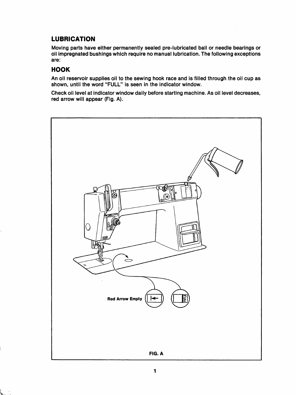
LUBRICATION
Moving
oil
are:
parts
Impregnated
have
HOOK
An oil
shown,
Check
red
reservoir
until
the
oil levelatIndicator
arrow
will
bushings
supplies
word
appear
either
permanently
which
oiltothe
"FULL"Isseen
window
(Fig. A).
sealed
pre-lubricated
requirenomanual
sewing
dally
In
before
hook
the
race
Indicator
starting
lubrication.
and
Is filled
window.
machine.
ballorneedle
The
following
through
As oil level
bearings
exceptions
the
oil
decreases,
cup
or
as
0
Red
Arrow
Empty(H-
FIG.
A
L.
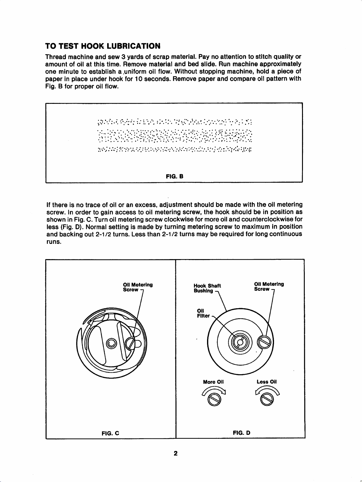
TO
TEST
Thread
amount
one
minutetoestablish
paperinplace
Fig. B
If
thereisno
HOOK
machine
of oilatthis
for
proper
trace
and
under
oil flow.
of oiloran
screw,inordertogain
shown
less
and
runs.
in Fig. C. Turn oil metering
(Fig. D). Normal
backing
out
2-1/2
LUBRICATION
sew3yardsofscrap
time.
Remove
a,uniform
hook
for10seconds.
material
oil flow.
excess,
access
to
oil
screw
material.
and
Without
Remove
FIG.
adjustment
metering
clockwise
settingismadebyturning
turns.
Less
than
2-112
Paynoattentiontostitch
bed
slide.
stopping
paper
B
should
screw,
the
for
metering
turns
mayberequired
•••
, " • # •♦•
more
Run
and
be
made
hook
oil
screw
quality
machine
machine,
compare
should
and
counterclockwise
approximately
hold a
oil
pattern
with
the
beinposition
piece
oil
metering
to maximum in position
for long
continuous
or
of
with
as
for
FIG.
Oil
Oil
Metering
Screw
C
Hook
Bushing
Oil
Filter
More
Shaft
Oil
FIG.
Metering
Screw
Less
Oil
D

Ifoilflow is not satisfactory, remove hook assembly and oil filter. Check filter. Oil wick
shouldbereplaced
sometimes
screw
clogged.
Oil
is not
Filter
indicates
securely
wheneverithas
that
the
filter
tightened.
Inspect
become
wick
has
all oil
clogged
become
with lint or dirt. An
detached
passagestosee
excess
from
the
screw
they have not
of oil
or
the
become
(S)
Hook
Assembly

MACHINE
1.
Move
2.
Lead
3.
Through3eyeletsofthread
4.
Units
5.
Down
6.
Into
7.
Over
8.
Uptoand
9.
Down
10.
Through
11.
Through
THREADING
needletohighest
thread
with
through
and
check
through
from
U.T.T.,
around
spring
through
needle
needle
thread
tension
thread
bar
eye
thread
through
retainer
and
thread
retainers
thread
from
point
stand
guard
pretensioner
assembly
under
slack
retainer
guide
lefttoright
through
thread
and
(2)
thread
regulator
take-up
post
eyelet
atop
machine
arm
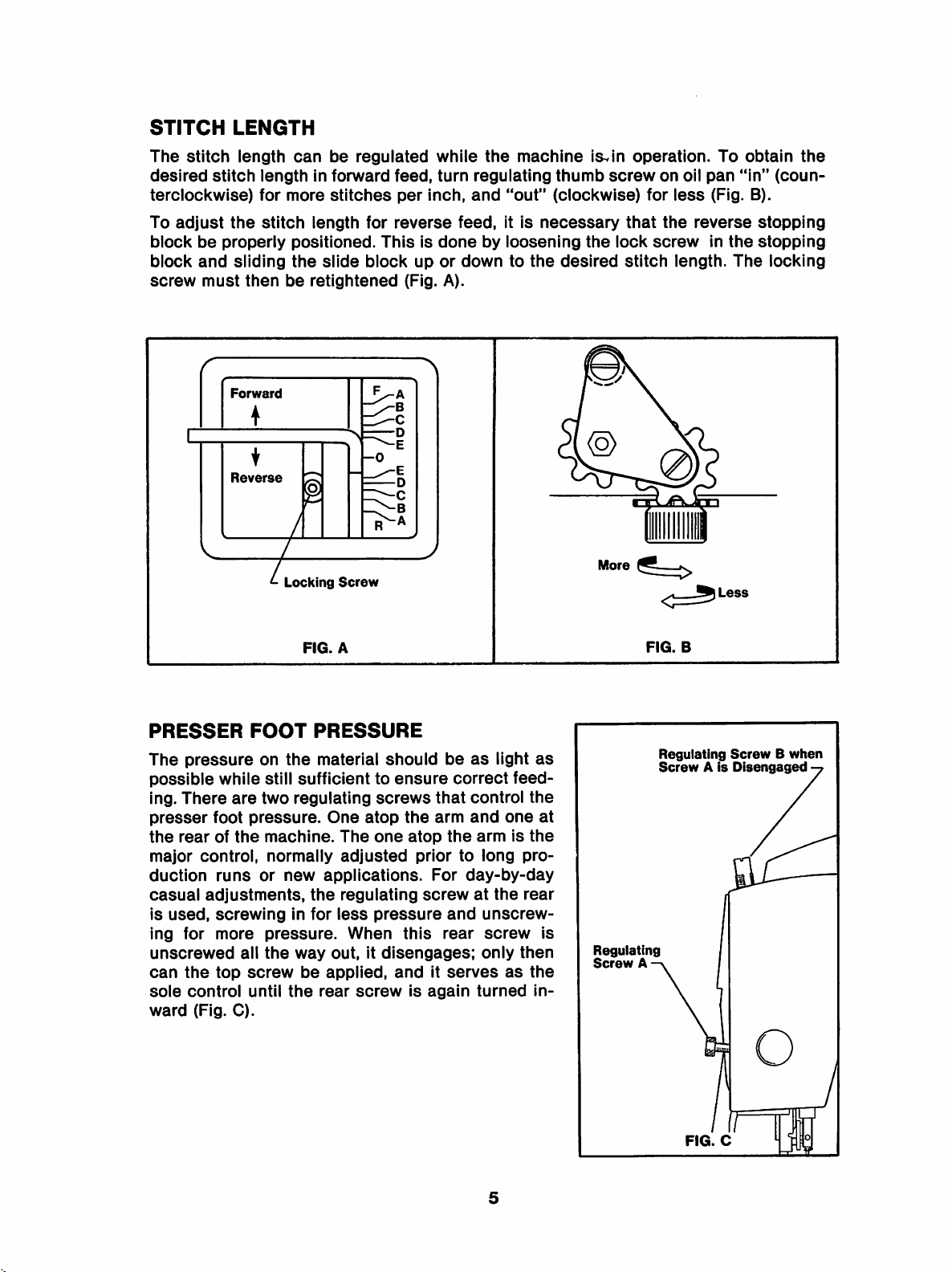
STITCH
The
desired
LENGTH
stitch
stitch
terclockwise)
To
adjust
block
block
screw
be
and
must
the
properly
Forward
Reverse
length
can
lengthInforward
for
more
stitch
length
positioned.
sliding
then
the
be
retlghtened
I
be
stitches
slide
regulated
feed,
per
for
reverse
ThisIsdone
block
(Fig. A).
-0
while
Inch,
turn
feed.
the
machine
regulating
and
"out"
It Is
by
loosening
upordowntothe
\s^'m
thumb
(clockwise)
necessary
the
desired
operation.
screw
that
lock
stitch
on
for
the
screw
oil
pan
less
(Fig. B).
reverse
In
length.
To
obtain
"In"
the
The
the
(coun
stopping
stopping
locking
PRESSER
The
pressure
possible
ing.
There
presser
the
rearofthe
major
control,
duction
casual
Is
ing
unscrewed
can
sole
ward
adjustments,
used,
for
the
control
(Fig.
Locking
FIG.
FOOT
on
the
while
still
sufficienttoensure
are
two
regulating
foot
pressure.
machine.
normally
runs
or
new
the
screwingInfor
more
top
all
screw
until
C).
pressure.
the
way
be
the
Screw
A
PRESSURE
material
should
screws
One
atop
the
The
one
atop
adjusted
applications.
regulating
less
pressure
When
out.Itdisengages;
applied,
rear
andItserves
screw
this
Is
be
as
light
correct
that
control
arm
and
the
armIsthe
priortolong
For
day-by-day
screwatthe
and
unscrew
rear
screw
only
again
turned
feed
one
as
as
the
pro
rear
then
the
In
at
Less
FIG.
B
Regulating
ScrewAis
ScrewBwhen
Disengaged
Is
Regulating
Screw
A
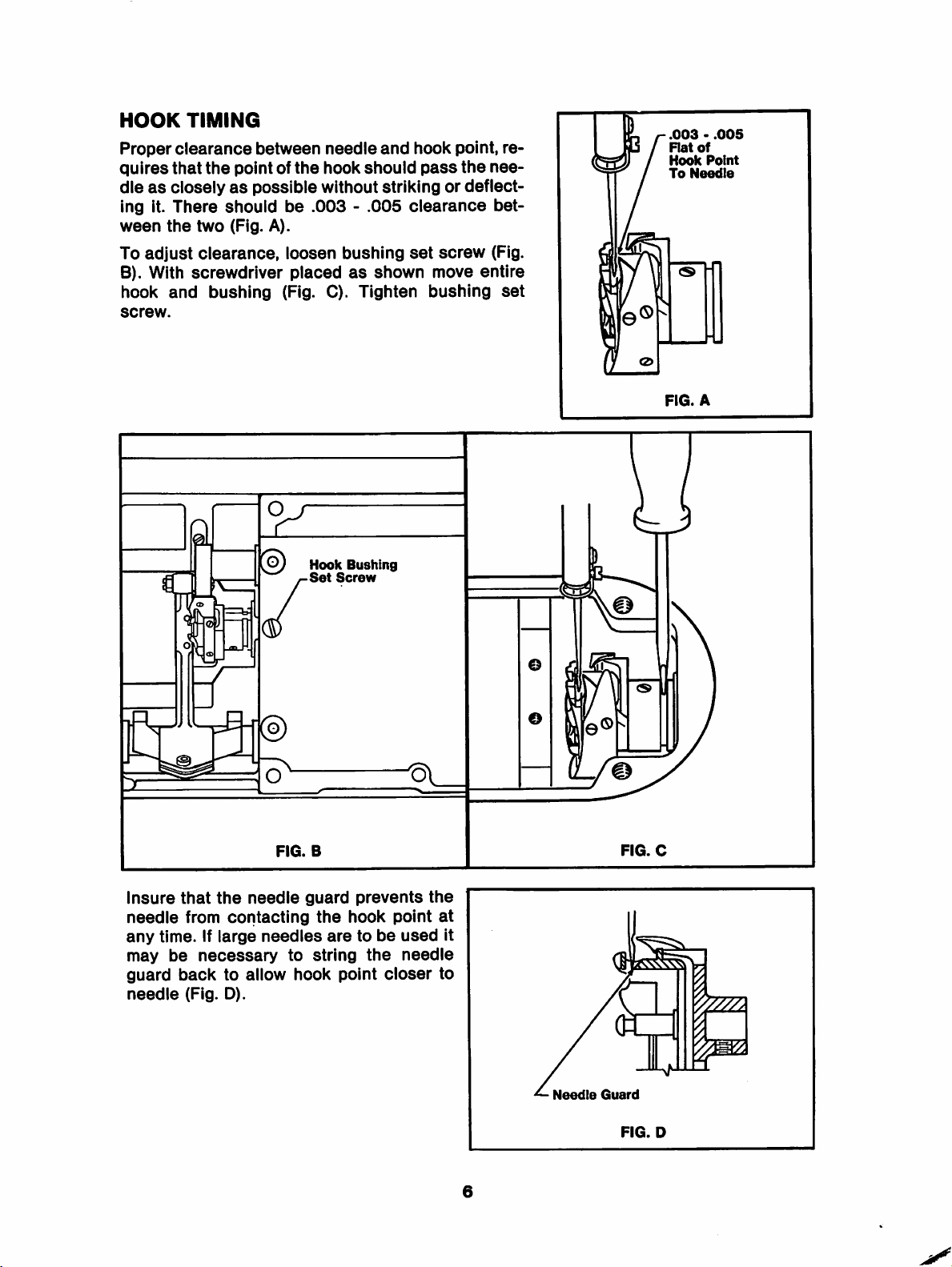
HOOK
Proper
quires
TIMING
clearance
that
the
between
pointofthe
dieascloselyaspossible
ing it.
ween
To
B). With
hook
screw.
There
the
adjust
and
shouid
two
(Fig. A).
clearance,
screwdriver
bushing
be
loosen
placed
(Fig. C).
needle
hook
and
shouid
hook
pass
without striking or
.003-.005
bushing
as
clearance
set
shown
Tighten
Hook
Bushing
Set
Screw
point, re
the
deflect
screw
move
bushing
nee-
bet
(Fig.
entire
set
.003•.005
Rat
of
Hook
Point
To
Needle
FIG.
A
FIG.
FIG.
C
D
Insure
needle
any
time. If
may
guard
needle
that
from
be
necessary
back
(Fig. D).
the
needle
contacting
large
needles
to allow
FIG.
to
B
guard
the
string
hook
prevents
hook
aretobe
the
point
point
used
needle
closer
the
at
to
it
Needle
Guard
6
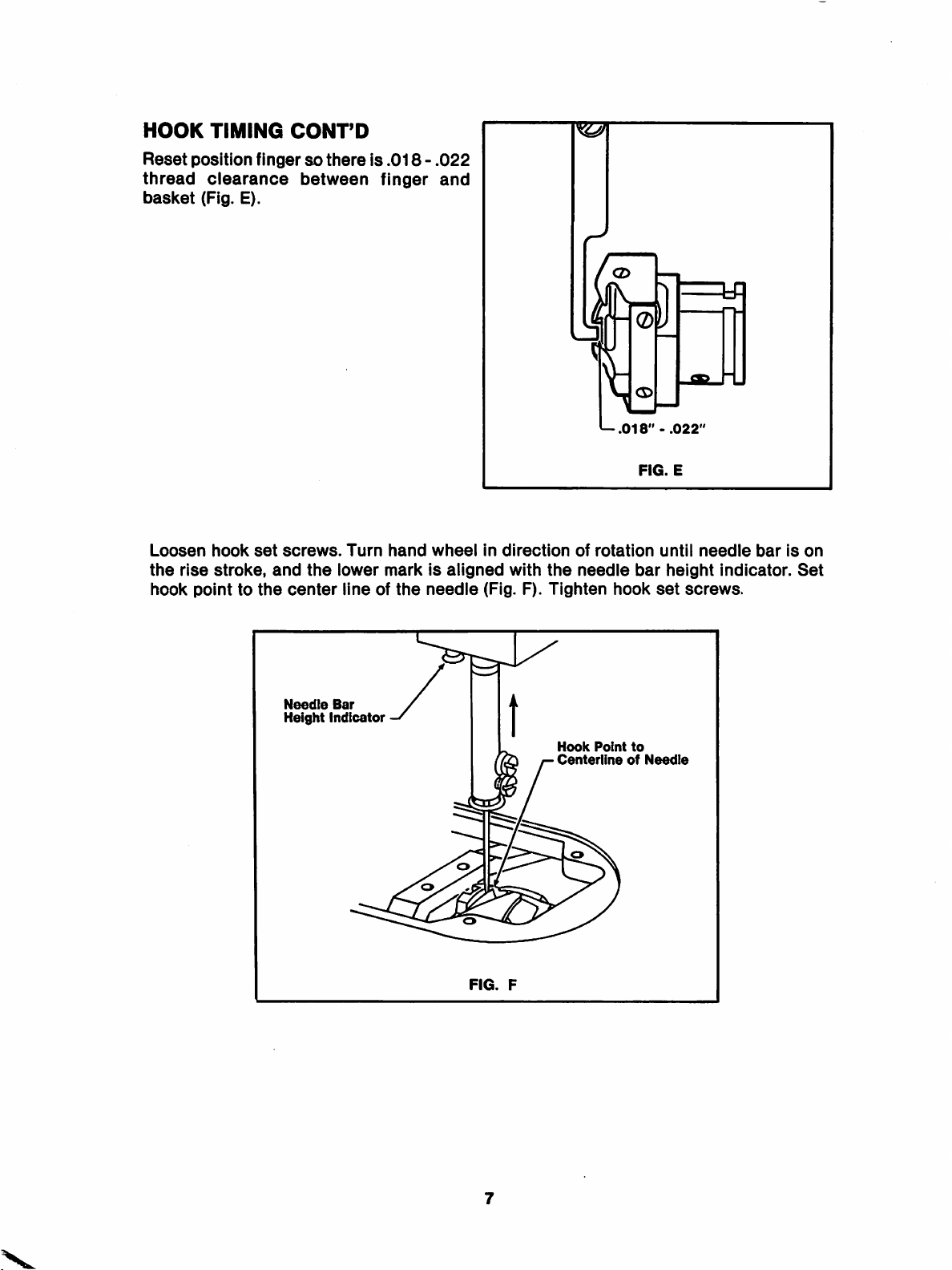
HOOK
Reset
thread
basket
TIMING
position
clearance
(Fig. E).
CONT'D
fingersothereis.018-.022
between
finger
and
Loosen
the
rise
hook
hook
set
stroke,
pointtothe
screws.
and
center
Needle
Height
the
indicator
Turn
lower
lineofthe
Bar
hand
wheel
in
markisaligned
needle
(Fig. F).
direction
with
of
the
needle
Tighten
Hook
Centeriine
^.018"
rotation
hook
Point
of
FIG.
bar
to
-
until
height
set
Needle
.022"
E
screws.
needle
indicator.
barison
Set
FIG.
F

TIMING
Manually
on
counterbalance
on
take-up
FEED
rotate
stud
LIFTING
arm
shaft
aligns
connecting
SHAFT
until
timing
with
timing
link (Fig. A).
TO
mark
mark
ARM
SHAFT
Timing
Marks
0
FIG.
A
Loosen
bed
shaft
(Fig. C).
pulley
Set
Screw
bed
until
Timing
set
shaft
screws.
®
(2)
timing
timing
marks
r
FIG.
belt
pulley
markatfeed
alignment
y
in Fig. A
TO
]
n
Q) ®
B
set
screws
bar
endofshaft
and
(Fig. B).
Fig. C
Hold
aligns
must
pulley
with
occur
stationary
timing
simultaneously.
FIG.
mark
Timing
C
and
on
Tighten
Marks
rotate
casting
8

FEED
DOG
SETTING
Centrally locate feed dog in throat plate slots. Feed dog must not make contact with
throat
plate,asnoted. Align by loosening
Feed
Dog
feed
FIG.
dog
A
screws.
No
Then
Contact
retighten
screws
Fig. A.
LATERAL
SETTING: Loosen pinch screw infeed bar crank
(Fig.
B).Shift feed barasre
quired. Ensure that feed bar does not contact position finger. Tighten pinch screw and
check
axial play at pendant link. Adjust feed lifting shaft to minimize play.
Leveling
Eccentric
Feed
Pinch
Height
Locking
Bar
Crank
Screw
Eccentric
and
Nut
FIG.
Leveling
Set
B
Screws
Eccentric
9

LENGTHWISE
crank
plate.
HEIGHT
To
protrude
adjust,
height.
pinch
SETTING:
.040"-.043"
loosen
Tighten
SETTING:
screw.
locking
Adjust
Positionsothat
With
feed
above
eccentric
the
locking
nut.
stitch
feed
dogatIts
throat
nut
length
dog
does
highest
plate.
and
turn
to
longest
not
contact
point
eccentric
the
stitch
either
full
depthofthe
until
and
loosen
feed
endofslotsInthroat
teeth
should
feed
dogIsat
correct
bar
LEVELING
Is
levelatthe
NOTE: It
other.
SETTING:
topofIts
may
be
Loosen
feed
necessary
set
screwsInfeed
path.
Tighten
to
set
feed
dog
set
bar
screws.
height
crank.
and
Turn
level In
eccentric
conjunction
until
feed
with
dog
each
10
 Loading...