

Page 1
SINGER
Instruction Manual
and
Parts List
® Singer is a registered trademark of The Singer Company Limited or its affiiiated companies.
© 2009 Copyright The Singer Company Limited
Page 2

Page 3

Zigzag Sewing Machine
Instruction Manual and Parts List
Contents
1. Safety Instructions..............................................................................................................................................................4
1.1. Important Safety Instructions..................................................................................................................................4
1.2. Safe Operation......................................................................................................................................................... 5
2. Product Description and Machine Specification............................................................................................................... 6
2.1. Product Description.................................................................................................................................................6
2.2. Machine Specification..............................................................................................................................................7
2.3. Motor, Motor Pulley and V-Belt Specifications.......................................................................................................8
2.4. Relationship between Zigzag Bight and Maximum Speed......................................................................................8
3. Setup and Adjustment Instructions....................................................................................................................................9
3.1. Table Cut-Out Drawing.............................................................................................................................................9
3.2. Oil Reservoir Installation........................................................................................................................................10
3.3. Belt Cover Installation............................................................................................................................................11
3.4. Lubrication.............................................................................................................................................................11
3.5. Needle and Thread.................................................................................................................................................13
3.6. Inserting the Needle..............................................................................................................................................13
3.7. Bobbin Case Removal.............................................................................................................................................14
3.8. Bobbin Winding.................................................................................................................................................... 14
3.9. Bobbin Case Threading..........................................................................................................................................15
3.10. Bobbin Case Repiacement................................................................................................................................ 17
3.11. Machine Threading............................................................................................................................................18
3.12. Stitch Length Adjustment..................................................................................................................................19
3.13. Presser Foot Pressure Adjustment...................................................................................................................19
3.14. Needle Thread Tension Adjustment.................................................................................................................20
3.15. Take-up Spring Regulation.......................................................................‘..........................................................20
3.16. Bobbin Thread Tension Adjustment.................................................................................................................20
3.17. Needle Position Selector...................................................................................................................................21
3.18. Stitch Width Regulator......................................................................................................................................22
3.19. Zigzag Stitch Width Control...............................................................................................................................22
3.20. Needle Bar Frame Clamp Device......................................................................................................................23
3.21. Straight and Zigzag Stitch Fitting.......................................................................................................................24
3.22. Spool Cap Usage................................................................................................................................................25
3.23. Anti-Spill Sleeve Usage......................................................................................................................................26
3.24. Knee Lifter Installation......................................................................................................................................26
3.25. Fittings for Buttonhole Stitching.......................................................................................................................29
3.26. Fittings for Hem Sewing....................................................................................................................................29
3.27. Fittings for Zipper and Cord Sewing..................................................................................................................30
-2-
Page 4

Zigzag Sewing Machine
Instruction Manual and Parts List
4. Maintenance...................................................................................................................................................................31
4.1. Machine Head Cleaning........................................................................................................................................ 31
4.2. Lubrication........................................................................................................................................................ ...31
4.3. Safety Inspection...................................................................................................................................................31
5. Troubleshooting..............................................................................................................................................................32
6. Parts List..........................................................................................................................................................................33
6.1. Face Plate, Arm Top Cover and Arm Side Cover Components............................................................................ 33
6.2. Thread Take-up, Arm Shaft and Handwheel Components...................................................................................35
6.3. Needle Bar, Presser Bar and Throat Plate Components.......................................................................................37
6.4. Zigzag Triangular Cam and Hook Advancing Crank Components.........................................................................39
6.5. Bight Amplitude, Bight and L-C-R Position Components............................................................................... .....41
6.6. Arm Shaft (upright) and Rotating Hook Drive Shaft Components
.......................................................................
43
6.7. Hook and Bobbin Case Components.....................................................................................................................45
6.8. Feed Regulating Dial and Feed Reverse Lever Components................................................................................47
6.9. Feed Mechanism Components..............................................................................................................................49
6.10. Presser Bar Lifter and Thread Tension Components
.......................................................................................
51
6.11. Accessories and Attachments...........................................................................................................................S3
6.12. Thread Stand Components............................................................................................................................... 55
6.13. Beit Cover Components and Extra Parts..........................................................................................................57
Page 5

Zigzag Sewing Machine
Instruction Manual and Parts List
1. Safety Instructions
1.1. l.’Tiportant Safety Instructions
When using this machine, basic safety procedures must be follow'-d Poad with attention all itistruction before
using the machine. When using the machine, undersland all basic safely instructions which are not limited to the
Items following. Read ail instructions, take care of this manual, and use it as rcfereitre when necessary.
• Before running the machine, make sura all relevant safety specifications are adequate to specifications
and technical rules in ycui country.
• The machine should not Oc run without its safety devices.
*■ Tile machine shoulrj only be operated by properly trained personnel.
• For your safety, goggles must be used r unning the nnachine.
• Turn off or unplug the machine when the follov.inj:' situations arise;
o Passing ttie thread by the needle or r eplacing the bobbin or looper.
o Replacing needle, presser fool, throat plate, feed dog and sliding piaie.
cj When the machine is in maintenance.
o When the operator is not running the madiine.
In case of lubricant oil contact with the eyes or skin, washed the surface with plenty of icy water wiUi a
generous amount of cold water. In case of ingestion, seek medical help immediately.
Repair, fitting or mair.tenatice shouid only be performed by properly trained personnel.
Maintenance and repair on electric equipment should only be made by qualified personnel. If cny
electrl;.. device is damaged, the machine should be immediately stopped.
Before starting the machine in full running, a test must be conducted to assure that machine and
operator are able to perform the task.
The .machine should not be placed next to a sound source as an ultrasonic welding machine and other
equipment.
The machine should only be run with the proper electric cable and connectors, and also the adequate
grounding.
The machine shouid only be used to sew materials as indicated.in its instruction manual, and
indications of use should be followed.
Singer will not be held responsible for any damage caused by unauthorized changes in the products.
Page 6

Zigzag Sewing Machine
1.2. Safe Operation
To avoid the risk of electric shock, do not open the motor wiring box and do not touch the components
assembled inside the wiring box.
To avoid injuries do not run the machine without the belt cover or in case any other safety device is
removed.
To avoid possible injuries keep fingers, head and clothes far from wheel, belt and motor when the
machine is running. Nothing should be placed near those parts.
To avoid injuries never put your fingers next to the rotating hook and the thread take-up lever cover
when the machine is running.
The rotating hook whirls at high speed while the machine is running. To avoid hand injuries, keep them
away from the rotating hook while the machine is running, turn off the machine to replace the bobbin.
To avoid possible injuries be careful when putting down or lifting the machine head.
To avoid accident in case of a sudden start of the machine always turn it off when laying it down, or
remove the belt cover and the belt.
If you machine is equipped with a servomotor, it does not make noises while being driven. To avoid a
possible accident caused by an unexpected start, be sure the machine is turned off.
Instruction Manual and Parts List
To avoid electrical shock, do not run the machine without proper grounding.
To minimize the risk of accidents or damage in electric components caused by electric discharge turn
the machine off before unplugging it.
Clean the machine periodically.
- 5 -
Page 7
Zigzag Sewing Machine
2. Product Description and Machine SpeciffditliDn
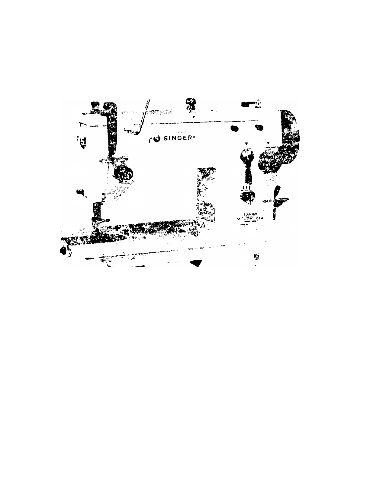
2.1. Product Description
Zigzag Sewing Machine
Instruction Manuai and Parts List
-6-
Page 8

Zigzag Sewing Machine
2.2. Machine Specification
Instruction Manual and Parts List
Table 1 - Machine Specification
Singer model
20U-109/ 109C 20U-112/112C 20U-309
For sewing
Stitch type
Max. speed^ 2,500 rpm
Max. stitch bight
Max, stitch length
Needle bar stroke
Presser bar lift (manual)
Presser bar lift (knee lifter)
Needle catalog (needle system)
Needle size
Machine pulley
Oil
Workspace (w x h)
Bedplate dimensions
Light to medium
Plain zigzag (Straight stitch)
2,000 rpm
9.0 mm 12.0 mm
5.0 mm
34.8 mm
6.35 mm
9.0 mm
Cat. 1910-05 (135x9)
See Section 3,5 "Needle and Thread"
74.0 mm effective dia, for v-belt
Singer Oil
211X 130 mm
399.0 mm x 178.0 mm
3-step zigzag
2,500 rpm
9.0 mm
Net weight (head only)
Gross weight (with accessories)
Noise^
Lower than 76 dBA at 1,600 spm
^ Maximum speed will vary depending on fabric, threads and sewing condition
^ Noise measurement according to DIN 4563-45-A 1.
21.0 kg
25.0 kg
Page 9

Zigzag Sewing Machine
2.3. Motor, Motor Pulley and V-Belt Specifications
• Vi HP (400W) 4-pole (medium speed) clutch motor
• M type v-belt
Table 2 - Machine Speed vs. Motor Pulley Diameter
instruction Manual and Parts List
Machine Speed [spm]
20U-109/109C j 20U-112/112C 20U-309
2,500 1
2,000
1,800
2,000 2,000 105
1,800 1,800 90 75
1,500 .1,500
2,500 130 105
1,500
2.4. Relationship between Zigzag Bight and Maximum Speed
Table 3 ” Relationship between zigzag bight and maximum speed
Machine Class
Zigzag bight
Max. Speed
20U-109/ 109C/309
0"'5.0 mm 5.0 ~ 9.0 mm 0 ~ 5.0 mm
2,500 rpm
2,000 rpm 2,000 rpm
Motor Puliey Diameter [mm]
SO Hz 60 Hz
85
SO
65
20U-112/112C
5.0 ~ 12.0 mm
1,800 rpm
-8'
Page 10
Zigzag Sevt/ing Machine
3. Setup and Adjustment Instructions
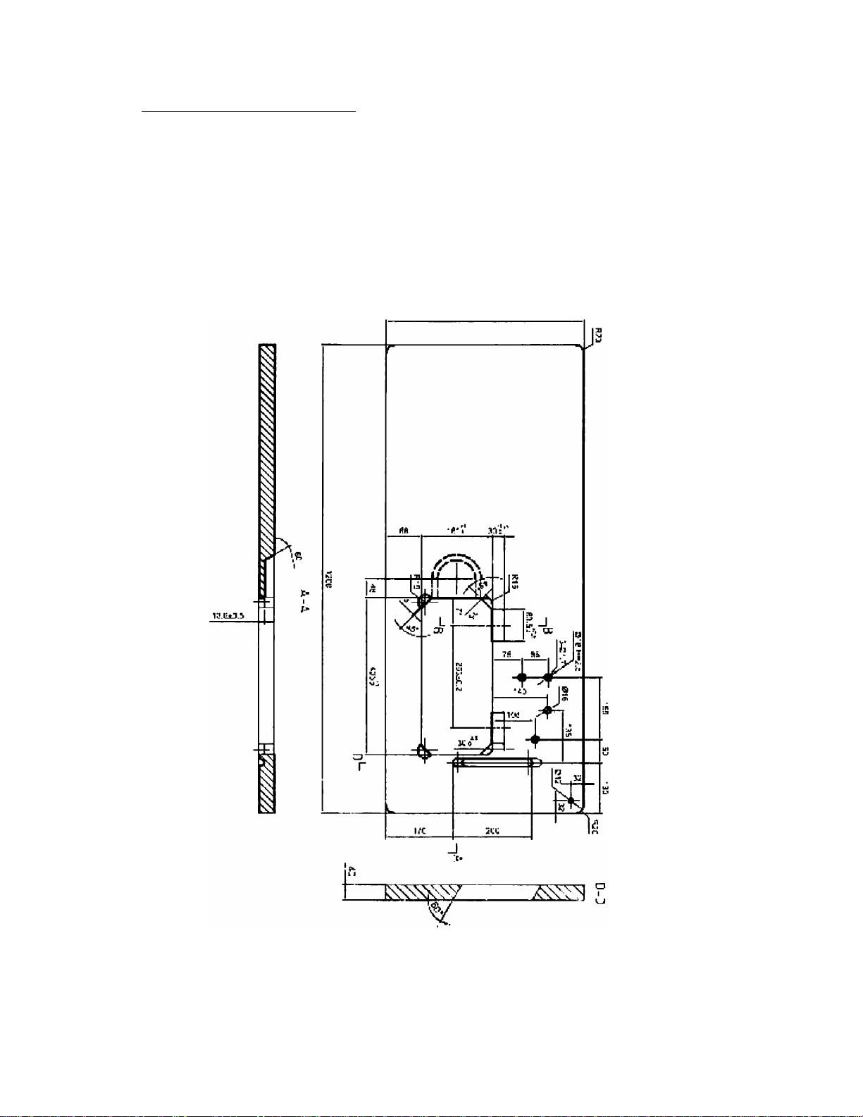
3.1. Table Cut-Out Drawing
Instruction Manual and Parts List
CF
I
OC
“I
50C
Figu 1
-9-
c
"I
Page 11
Zigzag Sewing Machine
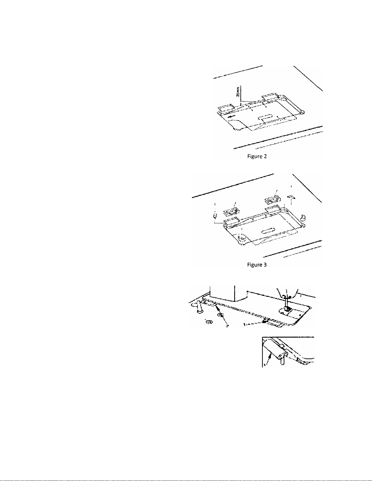
3.2. Oil Reservoir Installation
The oil pan should be fixed on the side of the
machine table groove by using four nails (Figure 2).
Instruction Manual and Parts List
Two rubber seats and two rubber corners for
supporting the head portion should be fixed on the
extended portion of the table by using nails, and the
other two rubber cushion on the hinge side should
be fixed on grooves by using nails too (Figure 3).
Two hinges fit into the hole in the machine bed, and
the machine head fitted the table hinge's rubber,
before the machine head Is placed to the cushions on
the four corners of the table (Figures 3 and 4).
Figure 4
10-
Page 12
Zigzag Sewing Machine
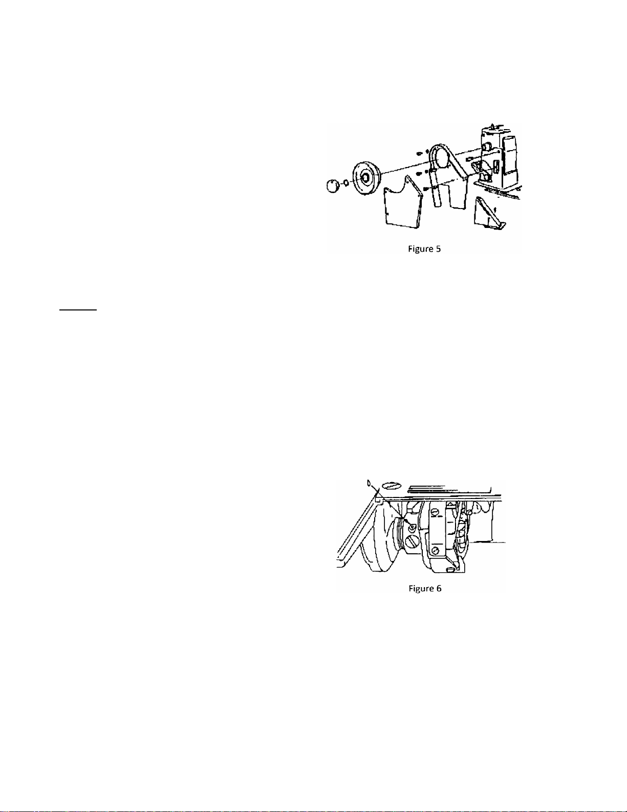
3.3. Belt Cover Installation
Above table surface
Align the belt guard so that hand wheel and v-belt
move freely, then screw it down is this position (see
Figure 5).
Below table surface
Install belt guard so that motor pulley and v-belt will
rotate freely without interference.
Caution:
• Switch off the machine.
Instruction Manual and Parts List
• Set sewing head upright again using both hands.
• Danger of crushing between sewing head and table top.
• For your safety, do not run the machine without the belt cover.
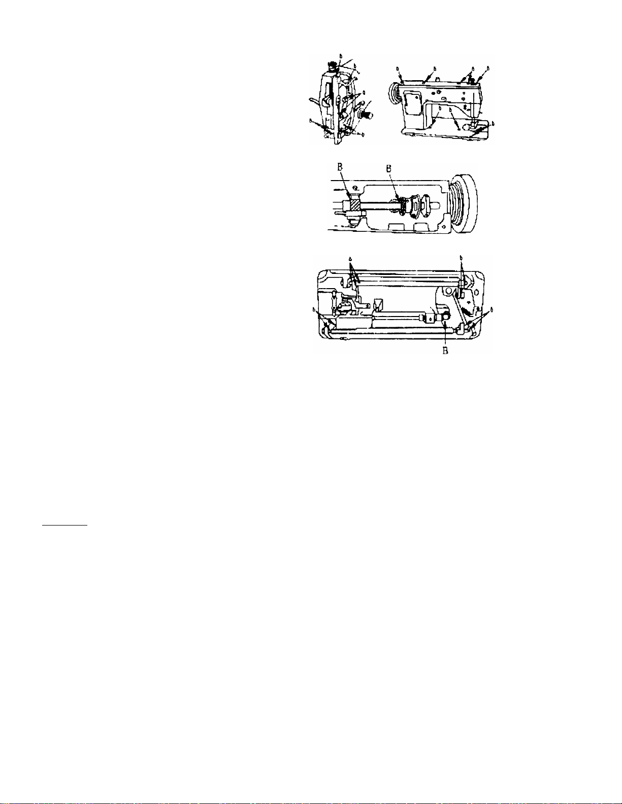
3.4. Lubrication
■Ò Rotating hook and area under throat plate.
Turn hand wheel over toward you until oil hole in
rotating hook appear in sight.
Apply one or two drops of oil to the oil hole (see
Figure 6).
11 -
Page 13
Zigzag Sewing Machine
Loosen and remove screws and remove face plate by
sliding it downward.
Remove screws and lift off arm top cover.
Clean and oil the places indicated with *Cf.
Apply sufficient oil to all oil felt shown in Figure?
Apply a small amount of grease to gear teeth
indicated with letter 'B*.
Also apply a drop of oil to all other oiling points shown
Keep oil pad 'A' under arm top cover saturated with
oil.
Instruction Manual and Parts List
Figure 7
Caution;
Switch off the machine.
Set sewing head upright again using both hands.
Danger of crushing between sewing head and table top.
For youf safety, do not run the machine without the belt cover.
Important:
When you first operate your machine after set up or after an extended period of disuse, oil the machine and run your
machine at 1,000 to 1,500 spm for about 10 minutes for the purpose of bread-in.
12-
Page 14
Zigzag Sewing Machine
Instruction Manual and Parts List
3.5. Needle and Thread
Selection of the proper needle depends not only on the machine model, but also on the material and thread used.
For selection of proper needle and thread sizes to be used on the various machine models please refer to the table
below
Model 20U-1Û9 / 109C / 112 / 112C / 309
Application
Max. thread size (Nm)-
Synthetic*
Needle size (1/lOOmm)
Needle catalog (Needle
system)
or an equivalent size of other types of thread
Light weight
materials
120
10(60)
1910-05 (135x9)
Caution:
• The power supply should be cut off before attaching the needle.
3.6. Inserting the Needle
Medium weight
materials
60
12 ~16 (80 ~100)
Mid-heavy weight
materials
30
18 ~ 19 (110 "'120)
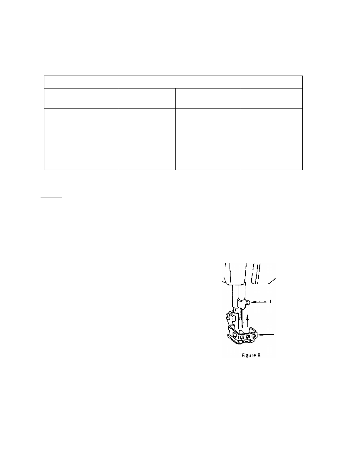
Use needle Cat. No. 1910-05 needle system (135x9)
only.
Raise needle bar to its highest position by turning
hand wheel toward you.
Loosen needle set screw '1' (see Figure 8) Insert the
needle in the needle bar and push it up as far as it will
go.
Make sure its long groove faces toward the front.
Tighten -needle set screw '1 securely.
Caution:
Switch off the machine.
Do not operate the machine without the finger guard '2' (see Figure 8).
13-
Page 15
Zigzag Sewing Machine
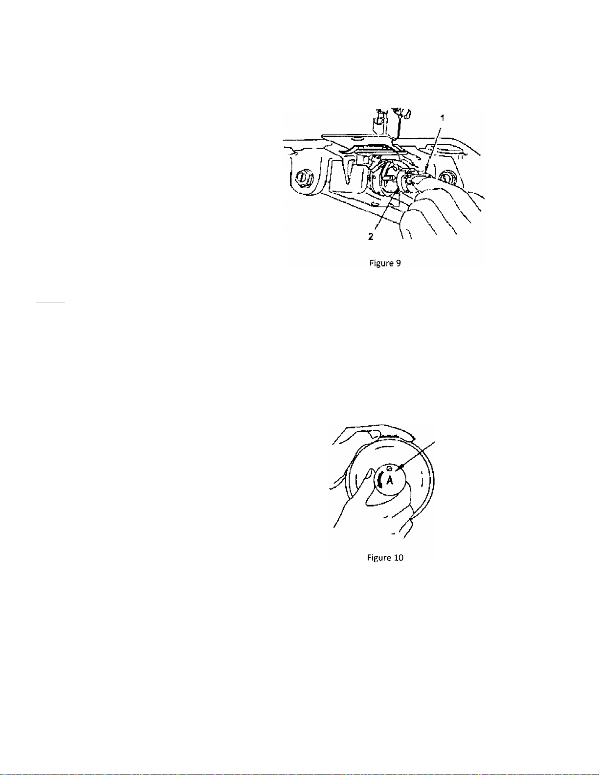
3.7. Bobbin Case Removal
Open bed slide.
Raise latch '1' (see Figure 9).
Lift out bobbin case '2' (see Figure 9).
Caution:
Instruction Manual and Parts List
• Switch off the machine.
• Do not operate the machine with throat plate left open.
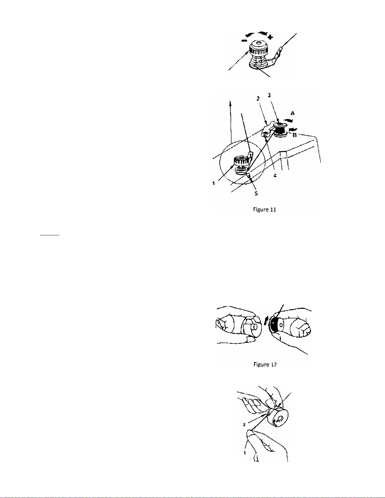
3.8. Bobbin Winding
Stop motion of needle by loosening stop-motion
screw '1', Figure 10. Hold hand wheel with left hand
and turn stop-motion screw toward you with right
hand.
-14-
Page 16
Zigzag Sewing Machine
Place bobbin on bobbin winder spindle '3'. Figure 11,
pushing it on as far as it will go.
Pre tension 'T (see Figure 11)
More tension
Instruction Manual and Parts List
Less tension
Push latch '2' in the direction indicated by arrow 'A',
then start the machine (see Figure 11),
Bobbin winder spindle '3', rotate in the direction
indicated by arrow 'B' (see Figure 11),
To adjust the amount of thread on bobbin, loosen
screw '4' on latch '2' and swing the latch '2' away
from you or toward you, as required.
For more thread on bobbin, swing latch '2' away from
you.
For less thread on bobbin, swing latch '2' toward you.
If thread winds unevenly on bobbin, loosen screw '5'
and move pre-tension 'V up or down, as required,
and tighten screw '5'.
Caution:
• Do not guide or hold thread when winding the bobbin.
Threading the pre-tension for bobbin winding
3.9. Bobbin Case Threading
Hold bobbin case so that thread unwinds in the
direction shown in Figure 12, and put bobbin in
bobbin case.
Put thread into notch '1', and draw it under tension
spring '2' (see Figure 13)
- 15
Page 17
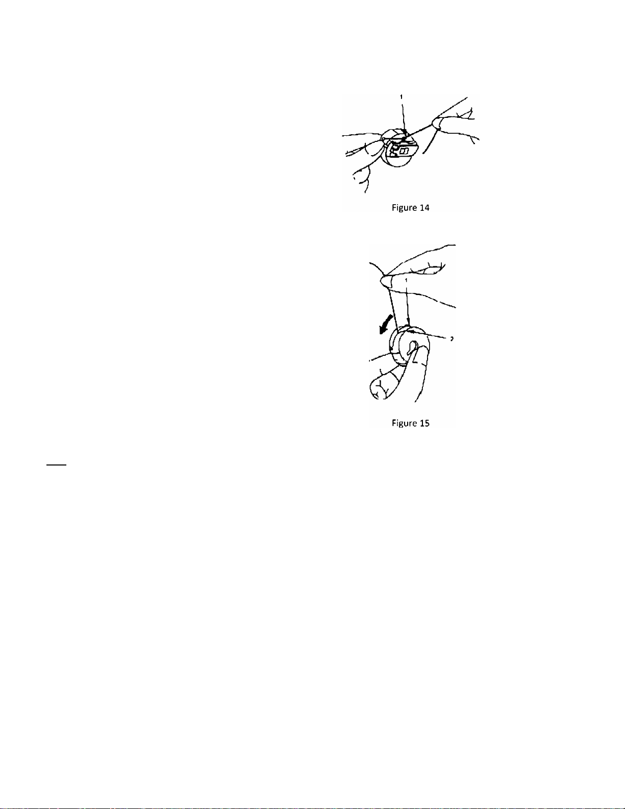
Zigzag Sewing Machine
Draw thread out from slot '2' on end of spring '1',
(Figure 14) and pass it through bobbin case thread
guide 'V, Figure 15.
Allow about 4 inches of thread to hang freely from
bobbin.
Instruction Manual and Parts List
Figure 13
Note:
• When straight stitching, a better result can be obtained if bobbin thread is not threaded through bobbin case
thread guide '1' of Figure 15.
' 16-
Page 18
Zigzag Sewing Machine
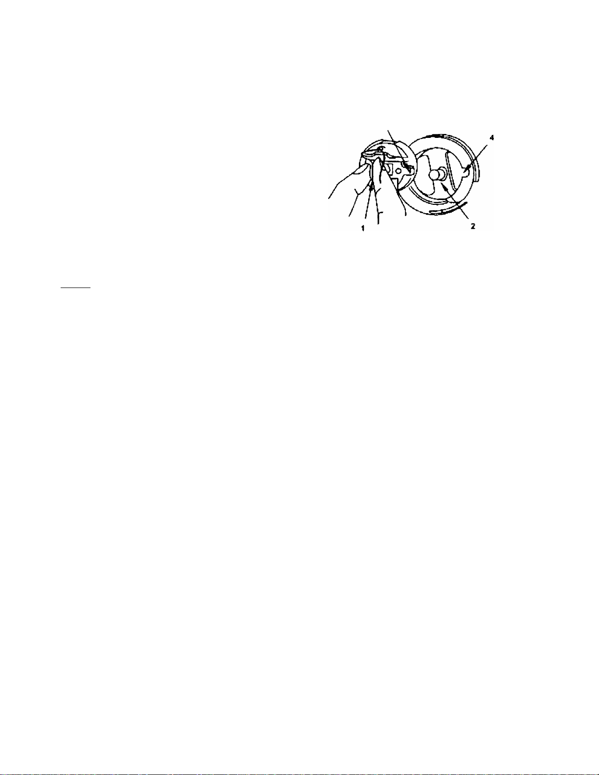
3.10. Bobbin Case Replacement
Hold bobbin case by latch '1' and place it on spindle of
bobbin case holder '2' so that position finger '3'
enters notch '4' at right of bobbin case holder (see
Figure 17)
Release latch and press bobbin case firmly in place to
assure proper position. Close bed slide
Caution:
• Switch off the machine.
Instruction Manual and Parts List
Figure 17
• Do not run machine without closing bed side. Danger of injury!
-17-
Page 19

Zigzag Sewing Machine
3,11, Machine Threading
Instruction Manual and Parts List
Figure 17
Lead thread from the thread unwinder through all the threading points in the order shown in Figure 17
Thread the needle from front to back, as show in Figure 17
Draw about 3 inches of thread through eye of needle.
Caution:
• Switch off the machine.
• Do not operate the machine without thread take-up guard.
• Do not operate the machine without finger guard.
-18.
Page 20

Zigzag Sewing Machine
3.12. Stitch Length Adjustment
Regulating the stitch length:
To regulate the stitch length, turn feed regulating dial
'1' Figure 18, toward left or right as required,
V to lengthen
to shorten
Changing to reverse feed:
Push lever '2 Figure 18 down for reverse feed and
release for forward feed.
To regulate the reverse stitch length, turn thumb
screw '3' Figuréis, toward left or right as required.
'+’ to lengthen
Instruction Manual and Parts List
to shorten
3.13, Presser Foot Pressure Adjustment
To regulate the presserfoot pressure, turn knurled
thumb screw '1', Figure 19, toward left or right as
required
'+' more pressure
less pressure
Figure 18
Figure 19
-19-
Page 21

Zigzag Sewing Machine Instruction Manual and Parts List
3.14. Needle Thread Tension Adjustment
Regulate needle thread tension with tension
regulating knob '1', Figure 20.
V more tension
less tension
3.15. Take-up Spring Regulation
Using a screwdriver in slot of stud '1', Figure 21,
regulate take-up spring tension by turning stud '1', as
required.
'+' More tension
Less tension
To adjust the amount of take-up spring movement,
loosen screw '2'. Figure 21, and set take-up spring
height by turning the entire tension assembly '3'
toward left or right, a$ required Securely tighten
screw '2'
3.16. Bobbin Thread Tension Adjustment
Regulate bobbin thread tension with tension
regulating screw '1', Figure22.
'+' More tension
Less tension
Figure 21
-20-
Page 22

Zigzag Sewing Machíne Instruction Manual and Parts List
3.17. Needle Position Selector
Left, Center and Right needle position settings are
available for placement of both straight and zigzag
stitching (see Figure23).
To position, push lever in and move to desired salting.
Do not make any needle position adjustment while
the needle is in the fabric.
Caution:
• Switch off the machine.
L
kl ÜI U
Figure 23
-21
Page 23

Zigzag Sewing Machine Instruction Manual and Parts List
3.18. Stitch Width Reguiator
The width of zigzag stitch is controlled with the spring
biased stitch width regulating lever ‘1', Figure 24.
Maximum zigzag width:
20U-109 / 109C / 309: 9.0 mm
20U-112/112C: 12.0 mm
Do not make any needle position adjustment while
the needle is in the fabric.
3.19. Zigzag Stitch Width Controi
To obtain minimum to'maximum width (20U-109,
109C, 309: 9mm or 20U-112,112C: 12mm) zigzag
stitches, first loosen thumb screw '2' to permit the
stitch width regulator '3' to return to its zero position
'A' and retighten thumb screw '2', according to Figure
25.
Then loosen thumb screw 'V, Figure 25, turn stitch
width regulator '3' clockwise as far as it will go and
while holding the regulator '3' in this position (see 'B',
Figure25), retighten thumb screw '1'.
You can now regulate the stitch width regulator
within the range of zero to maximum.
-22-
Page 24

Zigzag Sewing Machine
3.20, Needle Bar Frame Clamp Device
When straight stitching, a better sewing result can be
obtained by locking the needle bar frame immovable
with the ciamping device (see Figure 26).
'A' Clamp
'B' Release
Instruction Manual and Parts List
Caution:
• Switch off the machine.
A
Çl.lrtli»
Figure 26
Page 25

Zigzag Sewing Machine
3.21. Straight and Zigzag Stitch Fitting
General Purpose Presser Foot '1', Throat Plate 'T and
Feed Dog '3' as shown in Figure 27, are used for
straight and zigzag stitching.
Instruction Manual and Parts List
««Mir I JOU'-I N< t
WMPÏIMU'IU.IIIC'
2
Straight Stitch Presser Foot '1', Throat Plate '2' and
Feed Dog '3' as shown in Figure 28, are used for
straight stitching only.
Open bed slide, then remove throat plate, (Use
screwdriver 3' Figure 29, furnished with machine for
removal and replacement of throat plate and feed
dog.)
Using a screwdriver '2' remove bed plate '1' and
remove feed dog '4' (see Figure 29).
WWH lïPU l’ï'IIÏCI
<OtSOZ<»V
Figure 27
Figure 28
To replace general purpose or straight stitch feed dog,
fasten feed dog to machine temporarily and replace
general purpose or straight stitch throat plate. Set
feed dog correctly in position so that it will not hit the
edges of feed dog slots in the throat plate.
Replace bed plate and press it firmly in place.
Caution:
Switch off the machine.
Page 26

Zigzag Sewing Machine
3.22. Spool Cap Usage
When using a reel type thread spool, fit the spool cap
'1' supplied with the machine onto the thread spool
'3' (see Figure 31).
Set height of spool rest so there is approximately 2.0
mm clearance between top end of spool pin and the
tip of the slotted spigot of the spool cap (see Figure
31)
The spool cap should never be fitted on the spool pin
'5'. Forcing it onto the spool pin may result in
breaking the slotted spigot of the spool cap (see
Figure 31).
Instruction Manual and Parts List
O
Figure 31
•25‘
Page 27

Zigzag Sewing Machine
3.23. Anti-Spill Sleeve Usage
When using synthetic threads that easily spill off the
cone '1', slip the anti-pill sleeve '2' furnished with the
machine over the thread from the bottom of cone '1'
leaving the thread end to hang free at the top of anti
spill sleeve '2' as shown in Figure 32
Instruction Manual and Parts List
3.24. Knee Lifter Installation
Knee lifter mounting
Fasten knee lifter bracketto underside of table "T
145mm from table cut-out as shown in Figure 33
Figure 33
-26
Page 28

Zigzag Sewing Machine Instruction Manual and Parts List
Knee operating presser foot lift
Bell cranks '1' and '2' shown in Figure 34 are fastened
to tiio underside of the bed bell crank 'V is used for
lifting and lowering the presser loot with knee, and
bell crank '2' is used for controlling the stitch width .
To raise or lower the presser foot with knee, loosen
screw '4' holding the knee lifter shaft arm '3' and
move knee lifter shaft arm 3' just under the bell crank
'1', and firmly tighten screw '4',
Loosen the lock nut holding screw '7' and turn screw
'7' as required, so that the bent end '6' of knee lifter
shaft arm '3' will be almost horizontal when knee
lifter knee plate '5' is pushed as far as it will go in the
direction indicated with arrow 'A', then firmly tighten
the lock nut.
With knee lifter shaft arm '3' set in position as
described above, loosen screw '8' and move knee
lifter shaft arm '3' up or down as required, so that
height '10' from its bent end '6' to bracket '9' is 64
mm.
Raise presser foot '12' with presser foot litter
'11'.Then loosen the lock nut holding screw '14' and
turn screw '14' as required, so that knee lifter knee
plate '5' when pushed in the direction indicated with
arrow 'B', will stop at a point (presser foot '12' raised
approx. 9 mm from throat plate '13' surface) where
presser bar lifter '11' will drop down from its raised
position when presser bat is lifted a little higher than
its normal up position Then firmly tighten the lock
nut.
When knee lifter knee plate '5' is pushed in the
direction indicated with arrow 'B', the presser foot
'12' will rise and when knee plate '5' is released,
presser foot '12' will be lowered.
Caution;
• Switch off the machine.
• Set sewing head uprignv cgain using both hands.
• Danger of crushing betwee»' Scwing head and table top
Figure 34
-27-
Page 29

Zigzag Sewing Machine
Knee operating stitch width control;
Bell cranks '1' and '2' shown in Figure 35 are fastened
to the underside of the bed, Bell crank 'Г Is used for
lifting and lowering the presser foot with knee and
bell crank '2' is used for controlling the stitch width.
To control the stitch width with knee, loosen screw '4'
holding the knee lifter shaft arm '3' and move knee
lifter shaft arm '3' just under the bell crank '2' and
firmly tighten screw '4'.
Loosen the lock nut holding screw T and turn screw
'7' as required, so that the bent end '6' of knee lifter
shaft arm '3' will be almost horizontal when knee
lifter knee plate '5' is pushed as far as it will go in the
direction indicated with arrow 'A'. Then firmly tighten
the lock nut.
With knee lifter shaft arm '3' set in position as
described above, loosen screw '8' and move knee
lifter shah arm '3' up or down as required, so that
height '10' from its bent end '6' to bracket is 67 mm.
Loosen stitch width regulating plate thumb screws
'1Г and '12' so that stitch width regulator '13' can be
moved from zero to maximum stitch width. (20U-103
/ 109C / 308: 9mm or 20U-112 / 112C: 12mm). Loosen
the lock nut holding screw '14' and turn screw '14' as
required, so that knee lifter knee plate '5' when
pushed in the direction indicated with arrow 'B', will
stop at the maximum stitch width position of stitch
width regulator '13'. Then firmly tighten the lock nut.
Stitch width will become wider when knee lifter knee
plate '5' is pushed in the direction indicated with
arrow 'B' and will become smaller when knee plate is
released.
Instruction Manual and Parts List
Figure 35
Caution:
• Switch off the machine.
• Set sewing head upright again using both hands.
• Danger of crushing between sewing head and table top
Page 30

Zigzag Sewing Machine
3.25. Fittings for Buttonhole Stitching
Buttonhole Foot '1', General Purpose Throat Plate 'T
and Feed Dog '3' as shown in Figure 36 are used for
buttonhoie stitching.
instruction Manual and Parts List
GPCGS2 l20U-1(7%'1{«Ci]D9)
C0MD2 ITOU llZ'nZO
2
SnfiSdZ (JOU.IIZ'IIZC)
Figure 36
3.26. Fittings for Hem Sewing
Hemmer Foot '1', Straight Stitch Throat Plate '2' and
Feed Dog '3' as shown in Figure37 are used for hem
sewing.
5«1d}r-4i2
Figure 37
Page 31

Zigzag Sewing Machine
3.27. Fittings for Zipper and Cord Sewing
Zipper Foot '1', General Purpose '2' or Straight Stitch
'3'
Throat Plate and General Purpose '4' or Straight Stitch
'5'
Feed Dog as shown in Figure 38 are used for zipper
and cord sewing.
Instruction Manual and Parts List
ta u i i I30U -1 Ql'l QSC<
eoM«z |zau iizm2« h«m2(ZOU-iU'i 12C|
Caution:
• Switch off the machine.
Figure 38
Page 32

Zigzag Sewing Machine
4. Maintenance
4.1. Machine Head Cleaning
Clean the machine periodically with a soft and dry cloth to remove the excess of dust on the machine head.
Do not use any kind of lacquer thinner to wipe the surface.
4.2. Lubrication
If the machine was idle for a long time, lubricate the machine according to the instructions of topics 3.4.
4.3. Safety Inspection
Check periodically if all safety devices are properly Installed and adjusted.
Check if all fixing and supporting screws of the machine head are adequately tighten.
Check if the v-belt is not excessively worn and if it has the right tension.
Check if there is no overheating in the electrical motor and check if the power cord and plug are not damaged.
Instruction Manual and Parts List
Page 33

Zigzag Sewing Machine
5. Troubleshooting
Whenever sewing difficulty is encountered, check and make adjustments as follows.
instruction Manual and Parts List
Problem Possible Causes
1. Is machine properly threaded?
2. Are thread guides or tension disc area lintfree?
Needle
thread
breaks
3, Is needle-thread tension too tight?
4. Is needle bent or has a blunt point?
5. Is needle inserted correctly?
6. Is needle the correct size for thread & fabric?
7. Is thread free of slubs & knots?
8. Is bobbin threading correct?
Bobbin
thread
breaks
9. Is thread tangled or caught?
10. Is thread tension correct?
11. Does bobbin rotate smoothly?
12. Is needle inserted correctly?
Stitches
skip
13. Is needle bent or has blunt needle point?
14. Is size of needle & thread suitable for
fabric?
15. Is threading correct?
16. Is needle properly inserted?
17. Is needle bent?
Needle
breaks
18. Is needle the correct size for the fabric?
19. Is needle clamping screw loose?
20. Is the fabric pulled while sewing?
Fabric
21. Is feed regulating dial properly adjusted?
1. Correct needle threading
2. Remove lint & fluff in bobbin case & hook
3. Adjust needle thread tension
4. Insert new needle
5. Insert needle correctly
6. Select proper needle size & thread
7. Remove slubs & knots
8. Correct bobbin threading
9. Untangle thread from bobbin case & hook
10. Adjust needle & bobbin case thread tension
11. Check whether bobbin thread is wound correctly
12. Insert needle correctly
13. Insert new needle
14. Select proper needle size & thread
15. Correct needle threading
16. Insert needle correctly
17. Insert new needle
18. Select proper needle & thread for fabric
19. Tighten needle set screw
20. Do not pull fabric while sewing
21. Lengthen stitch length by feed regulating dial
Po.ssible Solutions
fails to
feed
Fabric
puckers
Rotating
22. Is presserfoot pressure adjusted properly?
23. Is needle threading correct?
24. Is needle point blunt?
25. Is thread tension too tight?
25. Is there any lint or fluff on feed dog?
22. Adjust correct presser toot pressure
23. Correct needle threading
24. Insert new needle
25. Adjust needle tension properly
26. Remove lint & fluff from feed dog
heavy
noise
Machine
27. Is there any lint in rolling hook?
28. Are electrical plugs properly connected?
27. Remove lint & fluff from rotating hook
28. Turn on power switch
fails to
start
29. Is power & light switch turned on?
29. Connect plug to power source
If you still have difficulty in sewing even after making adjustments, contact your nearest Service Center.
-32-
Page 34

Zigzag Sewing Machine
6. Parts List
6.1. Face Plate, Arm Top Cover and Arm Side Cover Components
Instruction Manual and Parts List
-33-
Page 35

Zigzag Sewing Machine
Instruction Manual and Parts List
No.
1 554113-383
Part No. Description
Thread Take-up Guard 1
2 606407 Take-up Guard Screw
109
1 1 1 1 1
Quantity
109C
1 1 1
3 606395 Face Plate Assembly 1 1 1
4 606632 Thread Guide
5
606633 Thread Guide Screw 1 1
6 606634 Screw
7
554118-385 Back Cover 1 1
8 606635 Screw
9 606433 Arm Top Cover Assembly 1
601433
Arm Top Cover Assembly
10 606636 Thrust Washer
11 606454
B/W Bracket Assembly
12 606637 Spring
13
606638 Friction 0-ring
1 1 1 1
2 2 2 2
4 4 4 4
1 1 1
1 1 1 1 1
1 1 1 1
1 1 1 1 . 1
1 1
GO207-8 Friction 0-ring
14 606452
B/W Regulating Plate
1 1
15 606453 Spring 1
16 606449 Spring
17
18
19 550032
606451 Hinge Stud 1
GS272-8
Hinge Stud
606439 Set Screw 1
B/W Lever Assembly
20 544208-005 B/W Lever Set Screw
21 606447 B/W Lever Stud
22
606448 B/W Lever Stud Ring 1
1 1
1 1
1 1 1
1 1 1
GZ202-8 B/W Lever Stud Ring
23 606446 B/W Regulator Assembiy
24
25
544208-005
606639
B/W Regulator Screw
B/W Tension Assembly 1
1 1
1 1
GR482/6-8 B/W Tension Assembiy
26
27
28 606441
29 606443 Tension Nut
606440 Bobbin Winder Tension Stud
606442 Bobbin Winder Tension Spring
Bobbin Winder Tension Disc 2
1 1 1
1 1 1
1 1
GL162-8 Tension Nut
30 606439 Screw
31 606602
32
606398 Eccentric Lock
GT150-8
33
34
35
606397 Eccentric Screw
554128 Stopper pin
554144 Stopper Spring
Arm Top Cover Screw 2
Eccentric Lock
36 544212-001 Stopper Screw
37
38
39
40
41
GK14fi-8
GP.lCo/ 8
GR232-8 Panel thread hook
GS132-8 Panel screw
GR480/2-8 Volume adjusting plate assembly
Stitrh^staff shield
f'ariei assembly
1 1 1
1 1
1 1 1
1
1 1 1
1 1
112
112C 309
1
1
1
1 1 1
1 1
1 1
1
1 1
1
1
2 1
2 2
1 1
1
1
1 ■
1
1
1
1
1
1
1
1
1
1
1
1
1
2
1
34
Page 36

Zigzag Sewing Machine
6.2. Thread Take-up, Arm Shaft and Handwheel Components
15
14
1«
^ 13
Instruction Manual and Parts List
Page 37

Zigzag Sewing Machine
Instruction Manual and Parts List
No.
1 606640
2 606475
3 606474
4 606641
5
6
7 606472
8
9 606468
10
11
12
13 606473
14
15
16
17 606444
18
19
20
21
22
23 504101
Part No.
Take-up Assembly
Take-up
Take-up Eyelet
Take-up Lever Link
606471 Conn. Link Cap Screw
606642
N/B. Connecting Link Assembly
N/B. Connecting Link
606466
Connecting Stud Assembly
Set Screw
606464
606467
606465
Hinge Pin Screw
Hinge Pin
Pin Washer
Take-up Crank
606643
606420
606469
Hinge Stud
Set Screw
Guide
Screw
606644
606484
601478
606478
Arm Shaft and N/B Crank Assembly
Arm Shaft
Arm Shaft
N/B. Crank Assembly
606477 N/B Crank Posh. Screw
504066 Position Screw
Crank Posh. Screw
24 606480 Bushing Set Screw
25
26 541606
27
28 541607
29 504028
30 606483
31 606482
32
33
34
35 606485
36 606487
37
38
39
40 154756
41
42
43 606712
44
606481 Front Bush
Bevel Gear Assembly
504066
Bevel Gear Set Screw
Worm Gear Assembly
541607-308
Worm Gear Assembly
Worm Gear Screw
Feed Eccentric Assembly
Feed Eccentric Screw
606482
606645
606480
Feed Eccentric Screw
Retaining Ring
Arm Shaft Bushing Screw
Arm Shaft Bushing, back
CSM Flanged Bushing
606488
505009
CSM Bushing Set Screw
CSM Clamp Washer
415763-383 CSM Clamp Screw
*' CSM Clamp Stop Screw
606489
601489
606420
Handwheel
Handwhae!
Scr«;w
Retaining Collar Assembly
606713
Retaining Collar screw
Description
Quantity
109
109C
112 112C
1 1 1 1
1 1 1
1
1
1
1 1 1
1 1 1
1 1
1 1 1 1
1 1 1
1
1 1
1 1 1
1 1
1
1 1 1 1
1
1 1
1 1 1
1 1 1 1
1
1 1 1 1
1
1 1
1 1
1 1
1
1 1
1 1
1 1
1 1
1 1 1 1 1
2 2 2 2
2
1
1
1
1 1
1 1 1 1
1 1
1 1 1
1 1 1 1
1
1 1 1 1
1 1 1 1
1
1
1 1
1 1 1 1
1
1
1
2 2 2
1 1
2
2
1 1 1
1
1
1 1
1 1 1
1 1
1
1 1
1 1 1
1
1
1 1
1 1
1 1
2 2
1 1
2 2
1 1
1 1
1 1 1
1 1
1 1
1 1
1 1 1
1
1 1
1 1 1 1 1
1
1
1
1 1 1
1 1
1
1 1
1 1
2 2 2 2
309
1
1
1
1
1
1
1
1
1
1
1
1
2
1
1
1
1
2
-36-
Page 38

Zigzag Sewing Machine
6.3. Needle Bar, Presser Bar and Throat Plate Components
17.
Instruction Manual and Parts List
18
?9
30
@-15
23
13
24
20
/
25
-16
ra
22
27
Nil
12
1-
37-
Page 39

Zigzag Sewing Machine
Instruction Manual and Parts List
No.
1 606646
2
3
4
5 606456
6
7
Part No, Description
Needle Bar
606461
Needle Bar 1
606463 Needle Clamp Screw
606647
Needle Bar Frame Assembly 1 1 1 1
Needle Bar Frame 1
606458 Indicator Plate
606459 Indicator Plate Screw
8 606457 Exec. Pin Set Screw
9
10 606460
11
12
13 606648
14
15
16 606594
17 606593
18 606600
606516 Set Screw
N/B Frame Pin
GR466-8 Needle Bar Tread Guard
GR252^8
Needle Bar Tread Guard
1910-05 Needle (1910-05 «14)
P/B Thumb Screw & Nut Assembly
606592 Presser Bar Thumb Screw
606649
Presser Bar Thumb Screw Nut
Presser Bar
Presser Bar Spring 1 1 1
Presser Bar Bracket Assembly
19 606599 Screw
20 606601
21 606650
Presser Bar Lifting Bracket
Presser Foot Assembly 1 1
606651 Presser Foot Assembly
22 606444 Presser Foot Screw
23 606652
606402
24
606403 Needle Plate Screw 1
25 606653
26 606404
Needle Plate 1
Needle Plate 1
Bed Plate Assembly
Bed Plate 1
27 606405 Bed Plate Spring
28
29
30 606399
606401 Bed Plate Screw 2
606654 Slide Plate Assembly
Slide Plate
31 606400 Slide Plate Spring
32 606401
Slide Plate Spring Screw 2 2
Quantity
109 109C 112 112C 309
1 1 1
1
1 1 1 1 1
1
1 1 1 1
1 1 1
1 1
2 2 2 2 2
1 1 1 1
1
1 1 1 1 1
1 1 1 1 1
1 1 1
1 1
1 1 1 1 1
1
1 1 1 1
1 1 1 1 1
1
1 1
1 1 1 1
1
1 1
1 1
1 1 1 1 1
1
1
1
1 1
1 1 1 1 1
1
1 1
1
1 1
1
1 1 1 1
1 1 1 1 1
1
1 1 1 1
1
1 1
1
2 2 2 2
1 1 1 1 1
1 1 1 1 1
1 1 1 1 1
2 2 2
- 38.
Page 40

Zigzag Sewing Machine Instruction Manual and Parts List
6.4. Zigzag Triangular Cam and Hook Advancing Crank Components
-41
-39-
Page 41

Zigzag Sewing Machine
Instruction Manual and Parts List
No.
1
2
3
Part No.
606420
606539
606655
Description
Set Screw
Cam Shaft Assembly
Cam Shaft 1 1
606655-308 Cam Shaft
4
5
606656
410031
410056
6 606542
7
8
606541
606444
9 606590
10
11
605589 Washer
606588
12 606657
606586
Cam Shaft Oil Wick
Zig Zag Cam and Gear Assembly 1 1
ZIg Zag Cam and Gear Assembly
Cam Shaft Collar Assembly
Collar Set Screw
Screw
Spring Washer
Oil Felt
Oil Reservoir Assembly
Oil Reservoir Assembly
13 606558 Oil Wick
14 606659
15 GW178 8
16 GR243
17 G2222-9
18
GC149-8
Oil Reservoir Bracket
Spring
Rubber Cap
Following Shaft
Leaning Gear
19 G5202-8 Sleeve Screw of Cam Assembly
20
21
22
24
25
26
27
28
GR461/2-8
G0226-8
G5166-8 Left-hand Screw
GS258-8 Screw of Drive Lever
GR458/3-8
G5202-8
G0164-8
GR460/-8
29 GS020
30 606664
31
606663
606538
606663-308
32
606545 Fork Eccentric Connection Pin
33 GS256-8
34 GS213-8
35
GR390/2-8
36 GZ175-8
37 GH210/3-8
38 GS216-8
39
GS217-8
Cam Assembly
Leaning gear Sleeve
Regulator Fork drive Lever Assembly
Washer Screw
Washer of Following Lever
Following lever Assembly
Screw of Following Lever
Slide Block Cap Screw
Zig Zag Stitch Reg. Fork 1 1
Zig Zag Stitch Reg. Fork
Zig Zag Stitch Reg. Fork
Screw of Locating Rack 1 1
Set Screw of Locating Rack Sleeve
Locating Rack Assembly
Differential Connecting Shaft
Differential Crank Assembly
Screw of Differential Connecting Bar
Connecting Screw for Sliding Block
40 GH179-8 Differential Connecting Shaft
41
42
G0177-S
GS219-8
if D'ffpienu''' ^.uur-e' ting Shaf^' J.
Screw of Differential Connecting Bar
Quantity
109 109C
1 1
112 112C
1 1
1 1 1
1
1 1 1
1
1 1 1 1
2 2 2
2
2 2
2 2
2
2 2 2 2
1 1
1 1
1 1
1
1
1 1 1
1 1
1 1 1 1
1
1
1 1
1 1 1
1 1
1
1 1
1 1
1 1
1
1
1 1
309
1
1
1
1
1
2
2
2
1
1
1
1
1
1
1
1
1
1
1
1
1
1
1
1
1
1
1
1
-40-
Page 42

Zigzag Sewing Machine
6.5. Bight Amplitude, Bight and L-C>R Position Components
• -^2
Instruction Manual and Parts List
9
t3
B
10
24
2S
32
26
0^
\
30
1
3-1
35
37 27
36'
41 -
Page 43

Zigzag Sewing Machine
Instruction Manual and Parts List
No. Part No. Description
1 606511
Screw
2 606571 Washer
3 606569 Stop Plate
4 606554
Lever Arm Reg. Screw Nut
109
2 2 2 2
2 2 2
2 2 2 2 2
2 2 2 2 2
109C
Quantity
112
112C 309
5 606553 Lever Arm Reg. Screw 2 2 2 2
6 606572 Screw
7 606577 Spring
8
606575
Regulating Plate (left)
2 2
2 2 2
1 1 1 1 1
1 1 1 1 1
9 606576 Regulating Plate (right) 1 1 1
10 606574
11
12
606573 Thumb Screw 2 2 2
606556
13 606665
606666
14
606667 Slide Block & Guide Assembly
606668
15 606546
16 606669 Slide Block Guide Assembly
606547
17 606670
18 606557
Reg. Plate Holder 1 1
Spring
1 1 1 1 1
1 1 1
Bight Amplitude Control Mech. Assembly 1 1
Bight Amplitude Control Mech. Assembly 1 1
1
1
Slide Block & Guide Assembly
1 1
Slide Block 1 1 1 1
1 1
Slide Block Guide Assembly
Guide Stud Set Screw
1 1 1
1 1
Slide Block Crank Assembly 1 1 1 1
606557-308 Slide Block Crank Assembly
19 606555
20 606549 Slide Block Crank Link
Slide Block Crank Set Screw
2 2 2 2 2
1 1 1
606549-308 Slide Block Crank Link
21
22
23 606552
24 606560
25 606518 Collar Set Screw 2
26 606562 Crank Shaft Bushing
27 554139-383
28 606564 Position Block Screw 2
29
30
606671
606551
Hinge Screw
Position Lever Arm
Guide Stud
Collar Assembly
Crank Shaft Knob Assembly
606568 Position Block Screw Washer 2
606673 Position Block 1
606563 Position Block
2 2 2 2 2
1 1 1 1
1 1 1 1 1
1 1 1
2 2 2 2
1 1
1 1 1
1 1 1 1 1
2
2 2
2 2 2
1
1 1
31 606674 Position Lever Screw 2 2 2 2
32 606566
33
34
606565 Position Lever Screw Pin 1 1 1 1
606675 Position Lever Screw Pin Nut
Position Lever Assembly
35 606675 Thumb Stud Nut
36 606676
37 554140-383
Thumb Stud Spring Washer 1 1 1 1
Thumb Stud 1 1
1
1
1
1 1 1 1
1 1 1 1
1 1
2 2
1
2 2
1
1
1 1
1
2
2
1
1
1
1
■ 42
Page 44

Zigzag Sewing Machine
6.6. Arm Shaft (upright) and Rotating Hook Drive Shaft Components
Instruction Manual and Parts List
■ 43.
Page 45

Zigzag Sewing Machine
Instruction Manual and Parts List
No. Part No.
1
541610 Bevel Gear Assembly
2
504101 Bevel Gear Set Screw 2
Description
3 606677 Arm Shaft Bushing, upper
4
5
6
7
8
9
10
11
12
13
14
15
16
17
18
19
20
21
22
23
24
25
26
606678 Arm Shaft (Upright) 1
606527
541609
504101
Upright Bushing, lower 1
Bevel Gear Assembly
Bevel Gear Set Screw
606585 Connection Screw
606536
606535
Hook Advance Crank Connecting Rod 1
Bevel Gear
606533 Upright Bushing, upper 1 1
606534
606679
Bushing Set Screw
Clutch Sleeve Assembly 1
504101 Clutch Sleeve Screw 2
504101
Clutch Sleeve Screw 2
606528 Connecting Stud 1 1
606523 Retaining Collar Assembly 1 1
504101
543914
Retaining Collar Screw 2
Screw Gear Assembly
504101 Gear Set Screw 2 2
606537
605680
541684
543944
504101
Arm Shaft (Upright) Assembly
Arm Shaft Oil Wick 2 2
Bevel Gear Assembly
Screw Gear Assembly
Screw Gear Set Screw 2
606681 Hook Drive Shaft Bushing 1
605525 Hook Drive Shaft Bushing 1
27
28
606420
606523
Set Screw
Retaining Collar Assembly 1
506523 Retaining Collar Assembly 2
29
30
504101
504101
Retaining Collar Screw
Retaining Collar Screw
606682 Hook Drive Shaft 1
606526 Hook Drive Shaft 1
31
32
33
34
35
36
606522 Hook Drive Shaft Bush
606420
Set Screw 1 1
541685 Bevel Gear Assembly 1
504101
606523
504101
Bevel Gear Screw
Arm Shaft (Upright) Collar Assembly
Arm Shaft (Upright) Collar Screw
Quantity
109 109C
1
112
112C 309
1
2 2
1
1 1
1
1 1
1
1 1 1
2
2
1
1
1
1
1
1 1
1 1
1
2
2
2
1
1
1 1
1
1
1 1
2
2 2
2
1
1
1
1
1
1 1
1
2
2
2 2
4
4
1 1
1
1
1
1
2
2
1
1 J
2
2
1 1
1
1
1
1
2 2 2
... _ ..2
1
1
1
2
1
1
1
1
1
1
1
-44-
Page 46

Zigzag Sewing Machine Instruction Manual and Parts List
6,7. Hook and Bobbin Case Components
16
&N;
12
15
45
Page 47

Zigzag Sewing Machine
Instruction Manual and Parts List
No. Part No.
1 606517
2
606518 Hook Shaft Collar Screw
3 606516
Hook Shaft Collar Assembly
Set Screw 1 1
Description
4 606519 Hook Shaft Bush, short
5
541689
504101 Bevel Gear Screw
6
7 606516
Bevel Gear Assembly 1 1
Set Screw 1 1
8 606515 Hook Shaft Bush, long
9 606520 Hook Shaft
10 606410
11 606444
12
606513
Gear Shield
Screw
Bobbin 1
13 606683 Rotating Hook Assembly
606683C
Rotating Hook Assembly
606514 Rotating Hook Assembly
606514C
Rotating Hook Assembly 1
14 606684 Rotating Hook Set Screw
15 606512 Bobbin Case Assembly
16 606510
17 606511
Hook Position Finger 1 1 1 1
Position Finger Screw
Quantity
109 109C
2 2 2
4 4 4
112 112C 309
2 2
4 4
1 1 1
1 1 1 1 1
1 1 1
2 2 2 2
1 1 1
1 1 1 1 1
1 1 1 1 1
1 1 1
1
1
1
1 1 1
1 1 1 1
1 1
1
1
2 2 2 2 2
1 1 1 1 1
1 1 1 1 1
2
1
1
46-
Page 48

Zigzag Sewing Machine
6.8. Feed Regulating Dial and Feed Reverse Lever Components
Instruction Manual and Parts List
2
28
47-
Page 49

Zigzag Sewing Machine
Instruction Manual and Parts List
No. Part No.
1
606618
2 606617
3 606609
4 554138-383
5
6
7
8
9
543803-004
544218-053
606610
606685
606611
10 606686
11
12
13
14
15
16
17
18
19
20
21
22
606494 Hinge Screw Nut
606496
606495
606509
606496
606494
606615
606434
606612 Spring
606614 Spring Bracket
606602
554131-467
551131-457
23 374564
24 554134
25
26
554136
504010-453
27 554135
28
544213-001
Description
Spring
Stud Lock Pin
Feed Regulating Stud
Feed Regulation Dial
Dial Screw Washer
Dial Screw
Hinge Stud
Feed Regulator & Fork Comp
Feed Regulator Assembly
Screw
Hinge Screw
Feed Connecting Link
Feed Fork Connection.
Hinge Screw
Hinge Screw Nut
Reverse Lever Link Assembly
Clamp Screw
Screw
Reverse Lever Assembly
Reverse Lever Assembly
Adjusting Screw
Adjusting Screw Friction
Indicator Plate
Indicator Plate Screw
Adjusting Screw Stopper
Stopper Set Screw
Quantity
109C
109
1
1 1
1
1 1 1
1
1 1
1
1 1 1
1
1 1
1 1
112 112C
1 1
1 1
1
1 1
1 1 1
1 1 1
1
1
1 1
1 1 1
1 1
1 1
1 1
1
1 1
1 1
2 2 2 2 2
2 2
2
2 2
1 1 1 1
1
1
1 1
1 1 1 1 1
1 1 1 1
1 1
1 1 1 1
1
1 1
1 1 1 1
1 1 1 1 1
1 1 1
1
1 1 1 1
2 2
1 1
1
2
1 1
1 1
1 1
1 1 1
2
1 1
1
1
309
1
1
1
1
1
1
1
1
1
1
1
-48-
Page 50

Zigzag Sewing Machine
6.9. Feed Mechanism Components
17
16
Instruction Manual and Parts List
13
17
16
15
20
19
!1
10 11
-49-
Page 51

Zigzag Sewing Machine Instruction Manual and Parts List
No.
Part No. Description
109 109C 112 112C 309
Quantity
1 606493 Connecting Rod Assembly 1 1 1 1 1
2 606434 Connecting Rod Cap Screw
3
606492 Oil Felt 1 1 1 1 1
4 606496 Hinge Screw 1 1
2 2 2 2
1 1 1
5 606494 Hinge Screw Nut 1 1 1 1
6
7
8 606508
9
606507 Feed Lifting Rock Shaft Assembly
606687 Roller and Stud 1 1 1 1 1
Lifting Rock Shaft Crank Assembly
606500
Crank Clamping Screw 1 1 1 1 1
10 606497 Screw Center
11
12 606505
13
14
15 606506
606498 Screw Center Nut 2
Feed Rock Shaft
606499 Feed Rock Shaft Crank Assembly
606500 Crank Clamping Screw
Feed Bar
16 606503 Screw Center
17 606504
18 606497
19 606498
20
606688 Feed Dog
Screw Center Nut
Screw Center
Screw Center Nut
606502 Feed Dog
21 606501 Feed Dog Screw
1 1 1 1 1
1 1
2 2 2
1 1 1
2 2
2 2 2 2
1 1
1 1 ’ 1
1 1 1 1 1
1 1 1
1
1 1 1 1 1
2 2
2 2 2
2 2 2 2 2
2 2 2 2 2
2 2 2 2
1 1 1
1
1
2 2 2 2
2
2
1
1
2
50-
Page 52

Zigzag Sewing Machine
6.10. Presser Bar Lifter and Thread Tension Components
23
/
instruction Manuai and Parts List
10
n
-51 -
Page 53

Zigzag Sewing Machine
Instruction Manual and Parts List
No.
1
Part No.
606598
Description
Hand Lifter Lever
109 109C 112 112C 309
1 1 1 1 1
Quantity
2 606597 Hand Lifter Lever Pin 1 1 1 1
3 606599 Screw 1 1 1 1 1
4 606413
5
606412
Tension Release Lever
Tension Release Lever Screw Spring
6 606411 Tension Release Lever Screw 1 1 1
1 1 1 1
1 1 1 1 1
1 1
7 410413 Thread Retainer 1 1 1 1 1
8 606518
Thread Retainer Screw
1 1 1 1
9 606416 Thread Guide 1 1 1 1 1
10 606444 Thread Guide Screw
11
12 606689
606414
Thread Guard Pin 1 1 1 1 1
Tension Assembly 1
1
1 1 1
1 1 1
13 606425 Tension Disc 2 2 2 2
14 606426
Tension Releasing Disc 1
1 1 1
15 606418 Tension Release Pin 1 1 1 1 1
16 606427
Tension Spring
1 1 1
1 1
17 606422 Thread Take-up Spring 1 1 1 1 1
18 606419
Tension Base Assembly
1 1 1 1 1
19 606421 Tension Securing Screw 1 1 1 1 1
20 606424 Tension Stud 1 1 1 1
21 606429 Thumb Nut 1 1 1 1 1
22
606428 Thumb Nut Washer
1 1 1 1 1
23 600420 Set Screw 1 1 1 1 1
24 606607
25 606608
Lifting Lever 1 1 1 1 1
Hinge Screw
1 1 1 1 1
26 606605 Connecting Rod 1 1 1 1 1
27 606604 Connecting Rod Pin 2 2 2 2
28 606506 Connecting Rod 1 1 1 1 1
29 606604 Connecting Rod Pin 1 1 1 1 1
30 606603 Bell Crank Assembly 1
31 606602 Screw
2 2 2 2 2
1 1
1 1
1
1
1
1
1
2
1
1
2
-52
Page 54

Zigzag Sewing Machine
6.11. Accessories and Attachments
22
23
24
20
•12
/ >r
10
V
/
15
14^ 7
Instruction Manual and Paits List
3
i 1
1 »
Jr-
O
1
-53-
Page 55

Zigzag Sewing Macliine
Instruction Manual and Parts List
No.
1 606690
2 1910-05
Part No.
Accessory Box 1
Needle (1910-05 #14)
3 606691 Zipper Foot
606692
4
606693
5
606694 Hemmer Foot Assembly
6
7 606695
8 606696
606697
9
10 606513
Presser Foot Assembly (for Button Holing) 1
Presser Foot Assembly (for Straight Stitching)
Needle Plate (for Straight Stitching)
Needle Plate (for Embroidery)
Feed Dog (for Straight Stitching)
Bobbin
11 606698 Oiler
12 606699
13
606700
14 606701
15
606702
16 606703
17
19
20
21
606704 Thread Unwinder Spool Net
606706 Drip Pan
6C6707 Drip Pan Nail
606708
GR759/25-8
22
606709 Machine Hinge
23 606710
24
25
606711
606707 Nail
Machine Rest Pin
Screw Driver(large)
Screw Driver(Small)
Screw Driver(for Needle Plate)
Thread Unwinder Spool Cap
Knee Lifter Assembly
Knee Lifter Assembly
Machine Hinge Cushion
Machine Cushion
Description
Quantity
109 109C 112 112C 309
1
3 3
1 1
1 1 1
3 3 3
1
1
1 1 1
1 1 1
1 1 1
1
1 1 1
1 1 1
1
1 ] 1
2 2 2 2
2
1 1 1
1 1 1 1
1
1 1 1
1 1 1 1
1
1
1
1
1 1
1
1
1 1 1 1
2 2 2
2
2 2 2
2
1 1 1
4 4 4 4
1 1
1 1
1
1
4
1
2 2 2
2 2
4 4 4
6 6
2 2 1
6 6 1
2
4 1
1
54-
Page 56

Zigzag Sewing Machine
5.12. Thread Stand Components
Instruction Manual and Parts List
Page 57

Zigzag Sewing Machine
Instruction Manual and Parts List
No. Part No. Description
Quantity
1 1013100900 Thread stand assembly 1
2
10122028
Rubber cap
3 10131008 Spool post (lower) 1
4 10131009 Spool post (upper) 1
5 10112039 Spool post joint 1
6 10112040 Spool arm (upper)
10112041
7
Spool arm (lower) 1
8 S04013 Screw 2
9
10113010 Thread guide
10 10131010 Spool pin 2
11
10128009
Spring washer
12 10128002 Washer 2
13 101S16006 Nut 2
14 10111013
Spool rest 2
15 10111014 , Spool retainer 2
16 10128010 Washer 2
17 10128006 Spring washer 1
18 N02003 Nut
19 10104003 Screw 2
20 101S11020 Nut 2
21 10102009 Spool rest cushion 2
1
1
2
2
2
-56-
Page 58

Zigzag Sewing Machine
6.13. Belt Cover Components and Extra Parts
Instruction Manual and Parts List
12
11
13
14
57
Page 59

Zigzag Sewing Machine
Instruction Manual and Parts List
No.
1
2
Part No.
281840-383 Belt Cover Assembly
281833-383
3 281834-383
4 549116
5
6
7
8
9
10
504063-451 Belt Cover (Upper) Screw
543875-104
544241 Belt Cover (Upper) Screw Stud 1
281835-383
549398
543803-003 Belt Cover (Lower) Wood Screw Washer
11 541515-001
12
504030
13 281822
14 410076
15
281833-308
16 281834-308
Description
Belt Cover (Upper)
Belt Cover (Upper) Cover
Belt Cover (Upper) Screw
Belt Cover (Upper) Screw Washer
Belt Cover (Lower)
Belt Cover (Lower) Wood Screw
Cloth Guide
Cloth Guide Thumb Screw
Finger Guard
Needle Plate Assembly (for Embroidery)
109
1
1
1
1
2
2
1
2
2
1
1
1
109C
1
1
1
1 1
2
2
1
1
2
2
1
1
1
Quantity
112
1
1
1
2
2 2
1
1
2
2
1
1
1
1
112C
1
1
1
1
2
1
1 1
2
2
1
1
1
1
309
1
1
2
2
1
2
2
1
1
- fif i-
Page 60

® Singer is a registered trademark of The Singer Company Limited or its affiliated companies.
© 2009 Copyright The Singer Company Limited
www.singer.com
P/N.xxxxxxxx
Printed in China
 Loading...