

Page 1
СО
L
ÄPWee*^*ff
г^
1^
РШШРЩЩвЩЯР
ШШШДй
ш
о
Z.
ш
шт^шштЁ^тштшттт^^^шшт^^
шшшт^^тштшйш^^^^^^
.. .
......
......................................^ -.,^:.^-.1-.::....1.:. ■■....
....
,.х /...— :
...
............... ..--«ь
Page 2
Page 3

PREFACE
Thank you for your purchase of this machine.
Please refer to this booklet for proper use and optimum service of this
machine.
CONTENTS
1. Setting up the machine ...................................................................... 1
1-1 Correct installation of the motor
1- 2 Connecting the controller to the motor
2. Overedging .......................................................................................... 3
2- 1 How to thread correctly .............................................................. 3
2-2 Preparation and checking prior to sewing .................................. 5
2- 3 Sewing ........................................................................................ 5
3. Double chain stitching (straight seaming)
3- 1 Changing from overedging to double chain stitching
3-2 How to thread correctly .............................................................. 7
3- 3 Sewing
4. Interlocking (Safety stitching)
4- 1 Changing from double chain stitching to interlocking
4-2 How to thread correctly ............................................................ 10
4- 3 Sewing ...................................................................................... 10
5. Thread tension adjustment ............................................................... 11
5- 1 How to adjust the overedging seams ...................................... 11
5-2 How to adjust the double chain stitching seams
6. Presser foot adjustment .................................................................... 13
7. Adjusting stitch length ........................................................................ I3
8. Sewing speed ................................................................................... 14
9. How to install the needle.................................................................... 14
10. Replacing the cutting knives ......................................................... 15
11. Lubrication ......................................................................................... 18
12. Checking and adjustment
13. Applicational notes ............................................................................ 17
13-1 How to set the presser foot for sewing knitted material
(used only for double chain stitching)
13-2 Double-hinged presser foot ..................................................... 17
13-3 Removing stitches of double chain stitching seams
14. Supplement ....................................................................................... 19
15. Changing the carbon brushes of the motor ....................................... 20
16. Specifications ................................................................................... 21
17. Table showing relationship between thread and cloth
.......................................................................................
............................................................
..................................................................
................................................
......................................
.........................................
................
................
.....................
.....................................
...............
.....................
1
2
q
6
8
9
9
12
18
17
18
22
Page 4
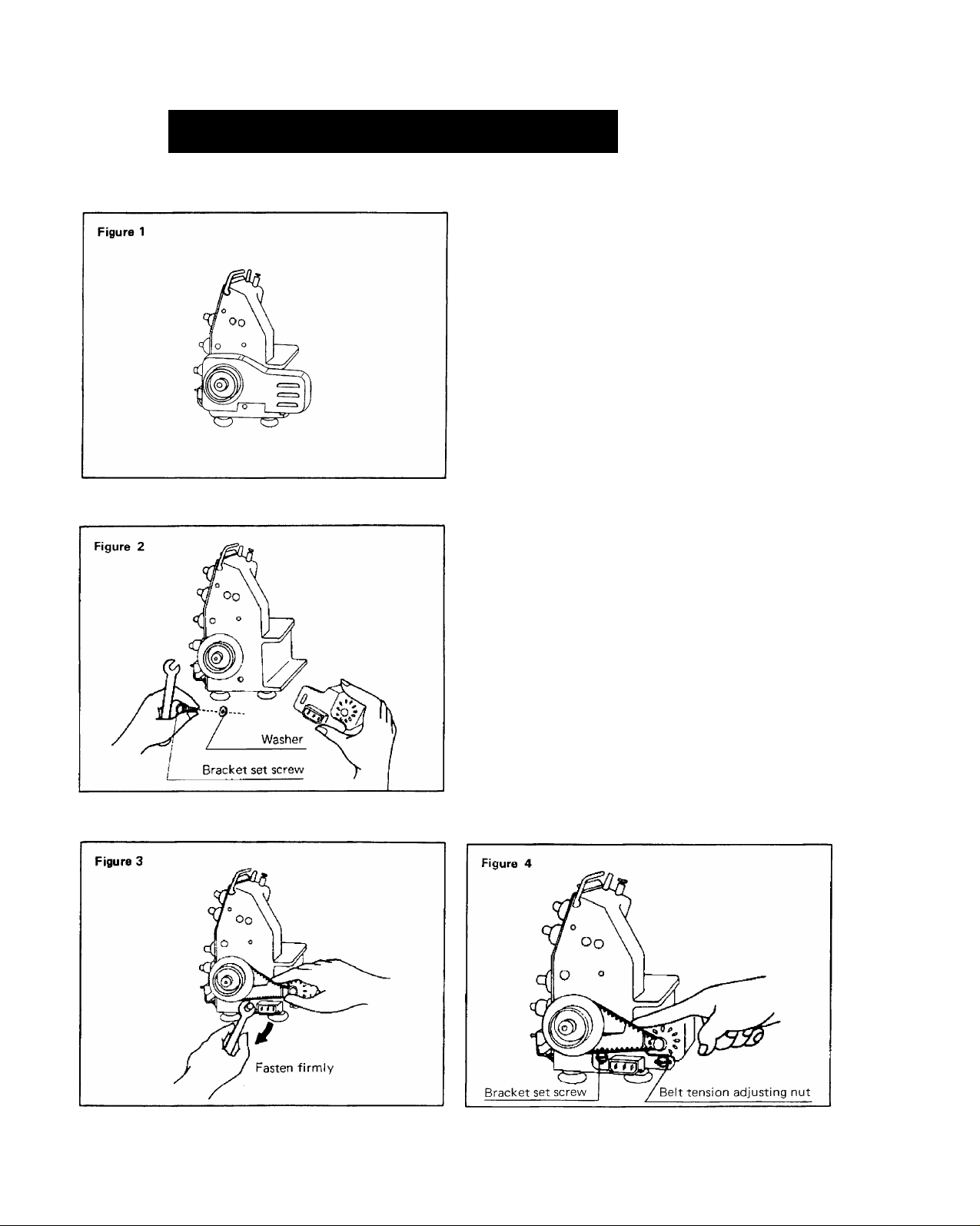
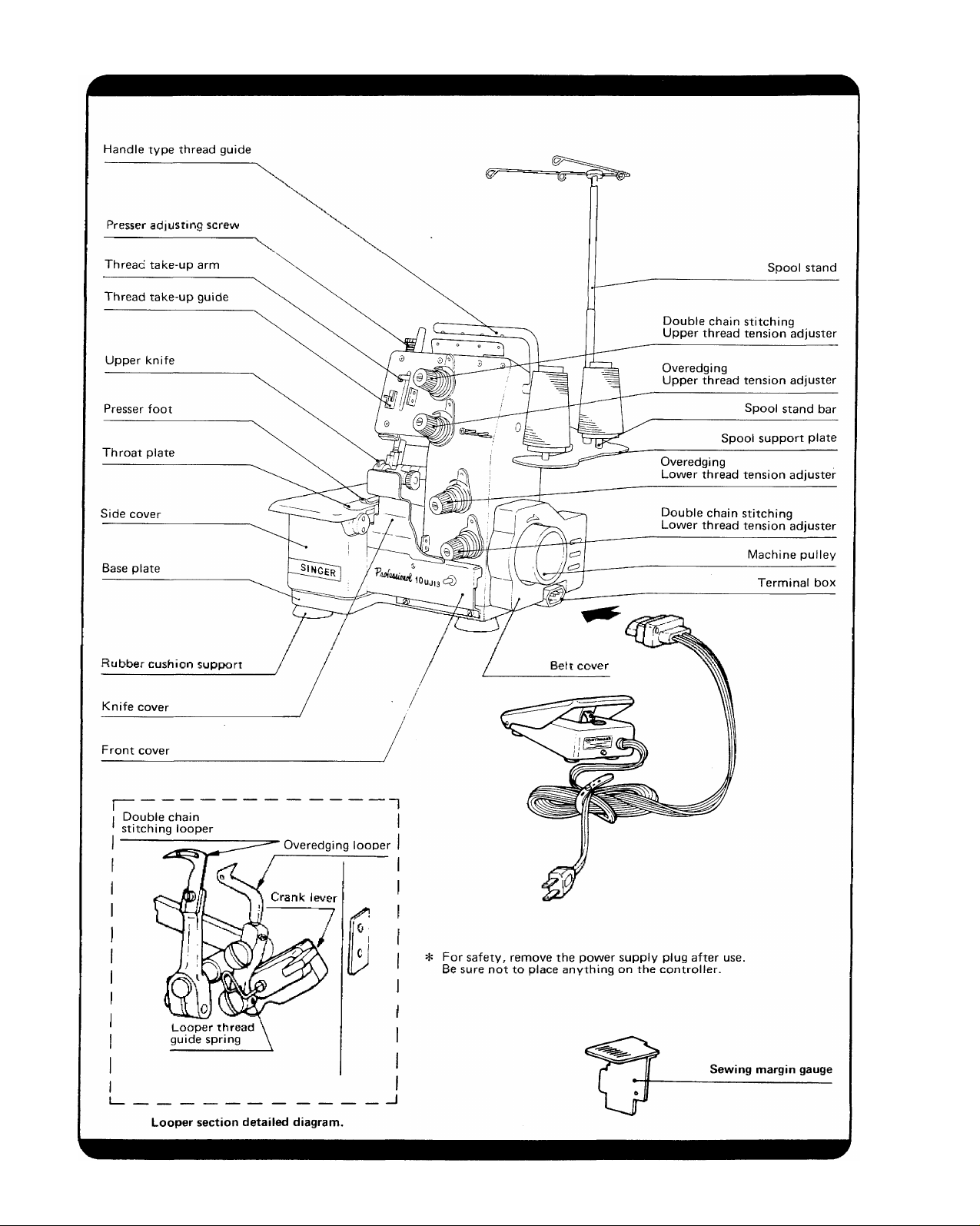
SETTING UP THE MACHINE
It is important that this sewing machine be set up
in the correct manner before use,
1-1 Correct installation of the motor
• Loosen the two belt cover screws and detach
the belt cover.
• The bracket set screw {Figure 2), bracket set
washer (Figure 2) and the belt are packed in
this set and attached to the machine body
by fastening the set screw while setting the
belt as shown in Figure 3.
Belt tension is considered adequate, if it
bends slightly when pressed by finger as
shown in Figure 4, When the belt tension is
not adequate, further adjust the tension by
moving the belt tension adjusting nut
(Figure 4) to the right or left.
• Replace the belt cover.
Page 5
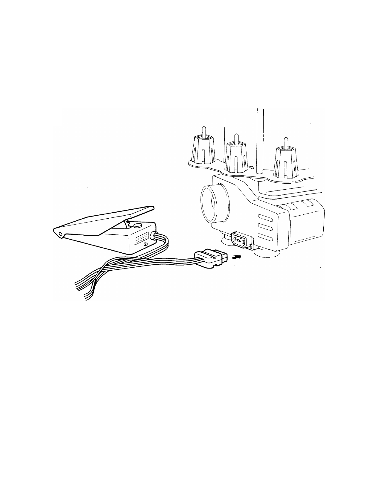
Figure 5
1-2 Connecting the controller to the motor
Connect the controller socket as shown in
Figure 5.
Next, insert the plug into the power source.
This machine runs faster when the controller
pedal is depressed with strong force, and the
speed decreases when the controller pedal is
lightly depressed.
*For safety, remove the power supply
plug after use.
Be sure not to place anything on the
controller.
Page 6
OVEREDGING
2
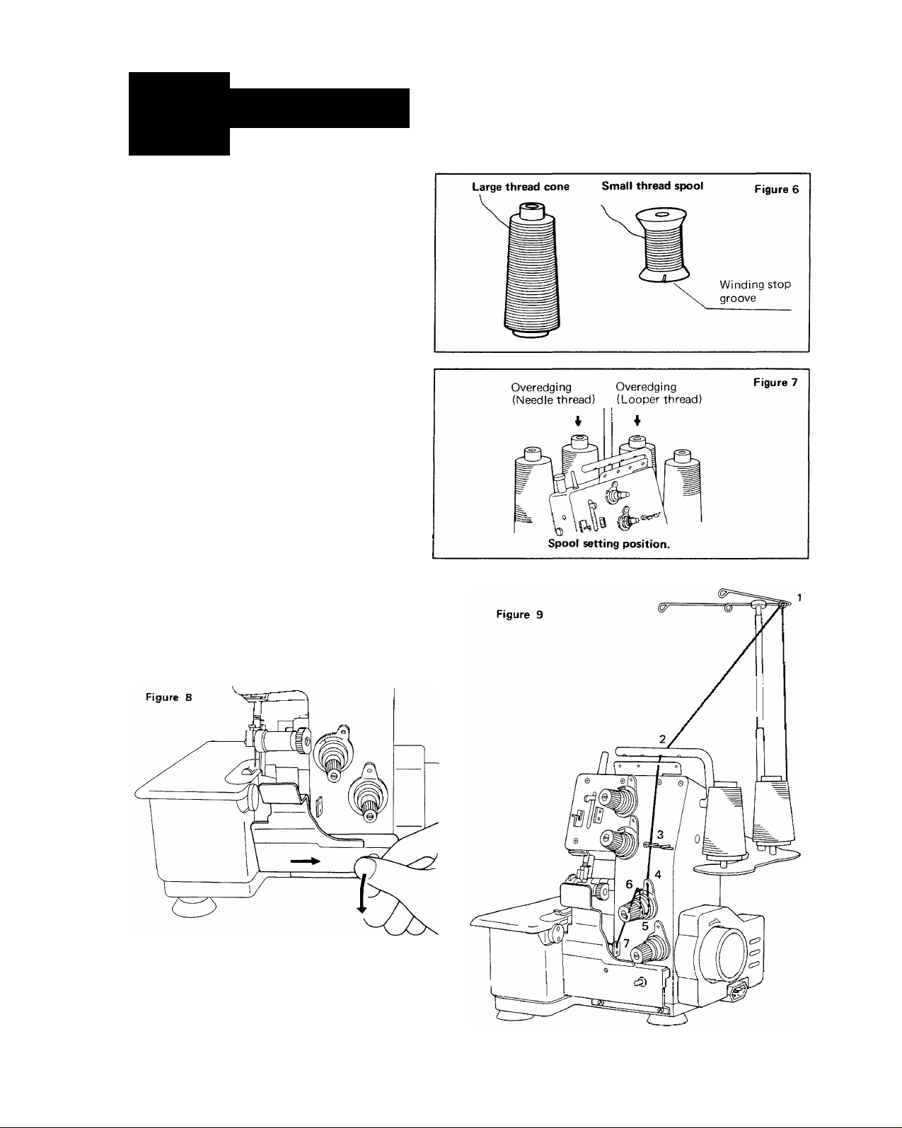
2-1 How to thread correctly
(1) Spool setting
Large thread cones (Figure 6) are
generally used for this machine, how
ever, it is possible to use small thread
spools (Figure 6) as well. In this case,
it is required that the thread spool be
set in such a way that the winding
stop groove in on the bottom.
(2) Lower thread (looper thread) insertion
First, open the front cover as shown in
Figure 8.
Then, the thread should be inserted in
the order as shown in Figure 9. After
inserting the thread, close the front
cover.
* Threading for overedging is diagramed
in red inside the side cover.
First pull the knob to the right and
then push downward.
Page 7
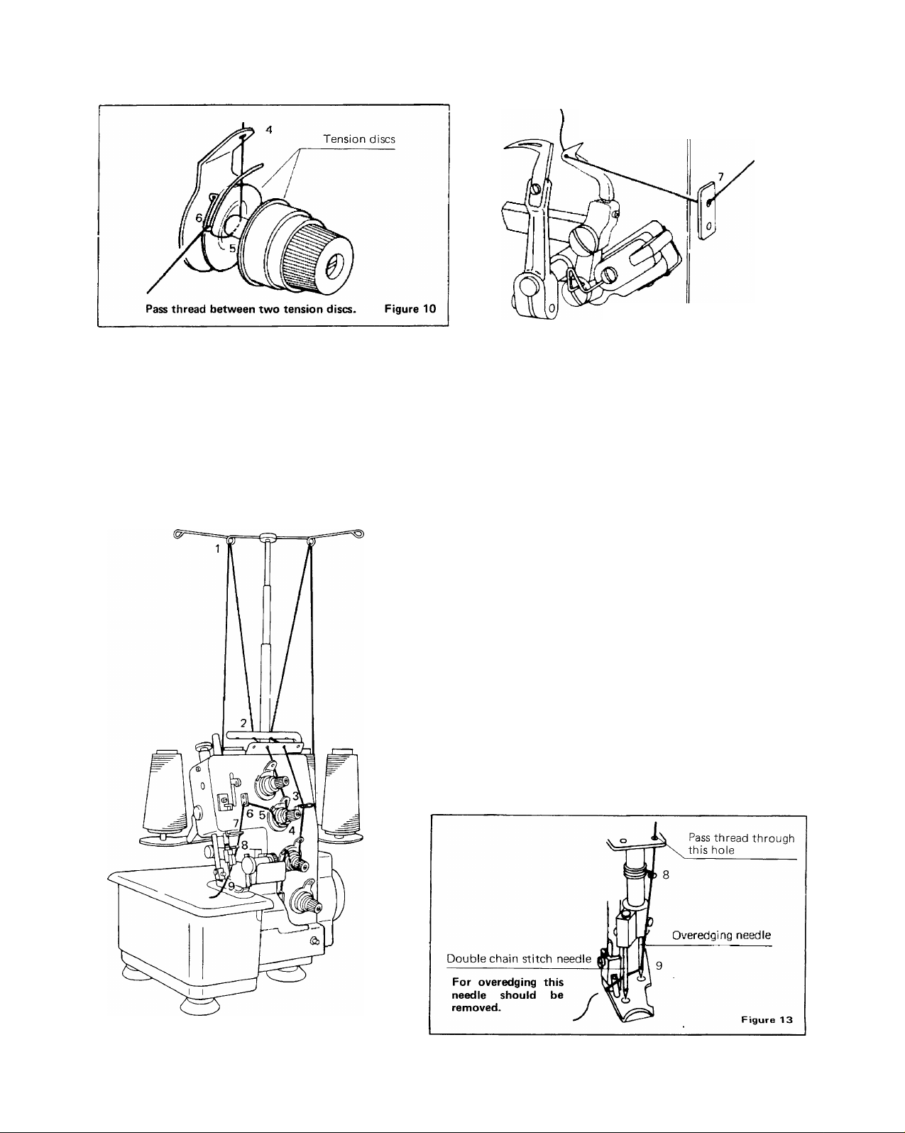
Figure 12
8 Correct threading at looper section.
Figure 11
(3) How to thread the upper thread correct
ly (needle thread)
The thread should be inserted in the
order shown in Figure 1 2.
After inserting the thread from the
front to rear through the needle eye
while facing the machine, the end of the
thread should be pulled out about 10
cm.
* Tweezers are helpful for threading
needle eyes.
Note: For overedging, the left-hand
needle should be removed (see
page 14)
Page 8
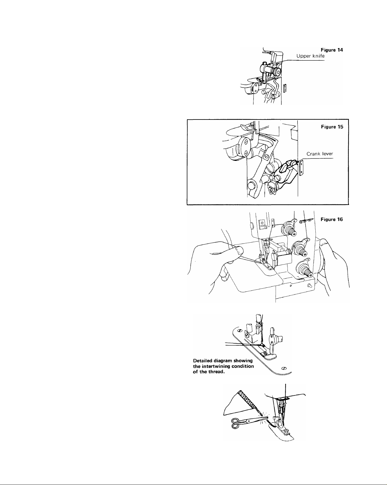
2-2 Preparation and checking prior to sewing
At the time of shipment, this machine is set
for interlocking. However, please recheck
the machine again in the order given below.
(1) Is the tip of the blade on the upper
knife facing in a downward direction?
(The knife should be in the position to
cut the cloth.) (Figure 14)
(2) Is the crank lever in the slot? (Figure 15)
(3) If the crank lever is not in the slot,
rotate the machine pulley by hand
placing the needle in the lowest posi
tion, At this point, the crank lever may
be set into the slot by pushing down
ward, thus allowing the looper for
overedging to operate.
2-3 Sewing
(1) After the completion of threading, hold
the ends of both the upper and lower
threads with the fingers of the left hand
creating a minor tension as shown in
Figure 16 and turn the machine pulley
with the right hand in the clockwise
direction.
Confirm that both threads are inter
twining. Then, set the cloth, and begin
to sew. (Figure 17)
(2) If the tension balance of the upper and
lower threads is not satisfactory, it is
possible that puckering will appear on
the cloth or that the seams will become
irregular.
Refer to the section "Thread tension
adjustment". (Page 11)
(3) After the seam is completed, continue
sewing about 3—5 cm at the end of the
cloth and cut the threads as shown in
Figure 18.
Figure 17
Figure 18
Page 9

DOUBLE CHAIN STITCHING
3
Figure 19
(STRAIGHT SEAMING)
3-1 Changing from overedging to double chain
stitching
It is required that all parts which are set for
overedging be changed for double chain
stitching in the order given below,
[Changing steps]
(1) Open the front cover and remove the
knife cover and set the sewing margin
gauge. Align the two round marks in
the same direction (Figure 19).
(2) As shown in Figure 20, press the knife
holder with a finger of the left hand and
rotate the upper knife holder knob
slightly upward with the right hand.
Then release the finger and rotate the
knob with the right hand until the
rotation comes to a stop with a click.
(3) Rotate the machine pulley by hand and
when the needle reaches its lowest
point, remove the crank lever from the
slot.
Then, the overedging looper will not
operate, (Figure 21)
(4) Remove needle from right side of needle
clamp and insert needle in left hand
needle hole in the clamp, (See Page 14)
Page 10

3-2 How to thread correctly
(1) Method for inserting upper thread
It is required that the thread be inserted
in the order shown in Figure 22.
After inserting the thread from the
front to the rear through the needle
eye while facing the machine, the end
of the thread should be pulled out for
about 10 cm from the needle.
^Tweezers are helpful for threading
needle eyes.
Tension discs
Pass thread between two tension discs. Figure 23
Figure 22
Page 11

(2) Method for inserting lower thread
Open the front cover, then insert the
thread in the order as shown in Figures
25 and 26. The end of the lower
thread also should be pulled out about
10 cm. After inserting the thread, close
the front cover.
In this case, the thread that has been
pulled out may be left as it is. There
is no need to pull it out to the surface
of the throat plate.
* Threading for double chain stitching is diagramed in
blue also inside the side cover.
3-3 Sewing
(1) Set the cloth as shown in Figure 27.
When beginning to sew, the first few
stitches should be made slowly.
(2) If the tension balance between the
upper and lower threads is not satis
factory, puckering may result in the
cloth or the seams will become irregular.
Please refer to the section "Thread
tension adjustment". (Page 11)
(3) After completing the seam, sew 3—5 cm
of additional stitching from the end of
the cloth as shown in Figure 28 before
cutting. With regard to disposal of the
thread chain, either tie the threads at
the edge of the cloth or, if the cloth is
of knitted material, fold back and fix
with a crochet needle.
In case the seam needs to be strength
ened, the same position should be sewn
twice in a parallel line.
Page 12

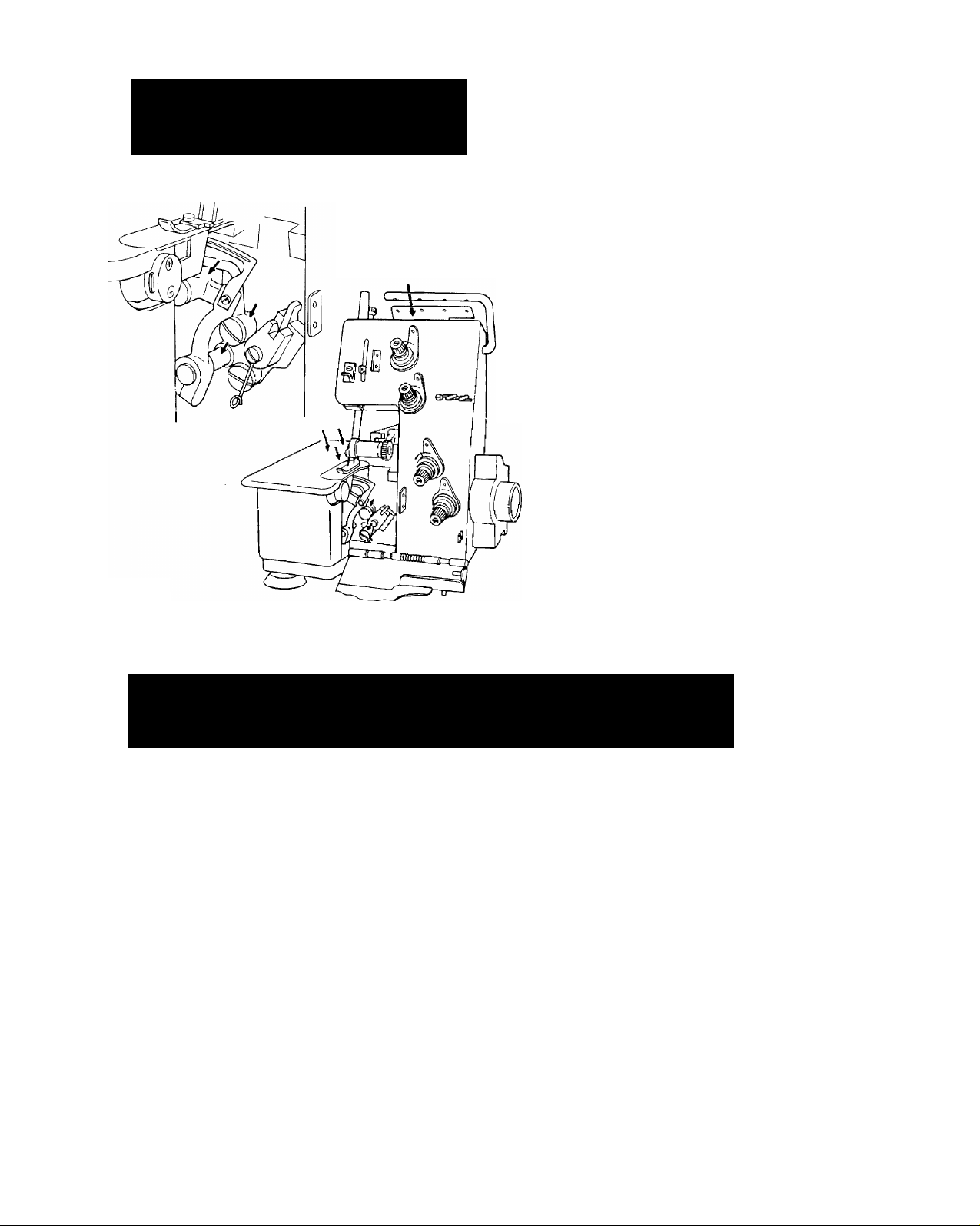
4 INTERLOCKING ( SAFETY STITCHING )
4-1 Changing from double chain stitching to
interlocking
All parts which are set for double chain
stitching must be changed to interlocking in
the order given below.
[ Changing steps ]
(1) Open the front cover and remove the
sewing margin gauge and insert the knife
cover. Align the two round red marks
in the same direction (Figure 29 & 30).
Figure 29
Figure 30
(2) As shown in Figure 31, pressing the
knife holder with a finger of the left
hand, rotate the upper knife holder
knob slightly forward with the right
hand. Then release the finger of the left
hand, rotate the knob until it comes to
a stop with a click. The tip of the blade
on the knife is then facing downward
and is in the operating position. It will
then be in a position to cut the cloth.
(3) Rotate the machine pulley by hand and
when the needle is at its lowest point,
pull down and set the crank lever.
Thus, the looper for overedging be
comes operational. (Figure 32)
(4) Insert overedging needle in right side of
needle clamp. (See Page 14}
Page 13

4-2 How to thread correctly
Overedging and double chain stitching can
be done simultaneously by using all four
threads as shown in Figure 33.
*Concerning threading, refer to the section
"How to thread correctly" for both
overedging and double chain stitching.
(Page 3 & 7).
4-3 Sewing
The sewing of interlocking is the same as
overedging and double chain stitching. Refer
to the section "Sewing" of both overedging
and double chain stitching. (Page 5 & 8)
^Concerning thread tension, refer to the
section "Thread tension adjustment".
(Page 11).
Figure 33
10
Page 14

THREAD TENSION ADJUSTMENT
5
5-1 How to adjust the overedging seams
Thread tension adjustment will differ ac
cording to the type of cloth, thickness, and
thread being used.
Adjust the tension using the upper and lower
thread tension adjusters while watching the
seams. (Figure 34)
Thread tension may be increased by turning
in a clockwise direction.
(1) When the tension of the lower thread is
too heavy (Figure 35), loosen the lower
overedging thread tension adjuster.
(2) When the tension of the upper thread is
too heavy (Figure 36), loosen the upper
overedging thread tension adjuster.
When the stitching seams appear as
shown in Figure 37, the tensions are
satisfactory.
(A) When the tension of the lower thread is too heavy.
Upper thread
(B) When the tension of upper thread is too heavy.
(C) Ideal stitching seam.
Figure 35
Figure 36
Figure 37
1 T
Page 15

Figure 38
Double chain stitch
Upper thread tension adjuster
Double chain stitch
Lower thread tension adjuster
5-2 How to adjust the double chain stitching
seams
Thread tension adjustment will differ ac
cording to the type of cloth, thickness, and
thread being used.
Adjust the tension using the upper and lower
thread tension adjusters while watching the
seams. (Figure 38)
Thread tension may be increased by turning
in a clockwise direction.
(A) When the tension of the upper thread is too light.
Front
(B) Ideal stitching seam.
Front
■ Figure 39
When sewing light-weight or knitted materi
als, the seams can be neatly finished if
the material is slightly pulled with the left
hand. (Figure 41)
Figure 40
1 2
Page 16

6
PRESSER FOOT ADJUSTMENT
The presser foot pressure of this machine
is adjusted for standard (medium) thickness.
Adjust only in the case when very thin or
very thick cloth is being sewn.
Sew thin cloth with less pressure, and,
thick cloth with more pressure.
*Turn presser adjusting screw clockwise
for more pressure and counterclockwise
for less pressure.
7 ADJUSTING STITCH LENGTH
Presser adjusting screw
Very thick cloth
f
Very Thin cloth
Medium thick cloth
How to adjust the pressure.
Less -A
More
Figure 42
(1) Holding the machine pulley with the
right hand, grasp the heart-shaped driver
(included in the accessories box) with
the left hand and loosen the feed
regulator fixing screw. The feed regula
tor fixing screw can be loosened by
turning the machine pulley in a counter
clockwise direction while pressing the
fixing screw with the heart-shaped
driver.
(2) Set the graduation on the feed regulator
knob to the indicator. The larger the
number on the feed regulator knob, the
larger the stitches will be.
(3) After completing adjustments, firmly
tighten the feed regulator fixing screw.
13
Page 17

3 SEWING SPEED
The machine has a maximum speed of 1,500
SPM. The speed can be controlled by pedal
depression on the controller.
"^The electric motor used for this machine is
a special motor designed for use only with
this machine and should not be used for other
purposes.
9
HOW TO INSTALL THE NEEDLE
With regard to the needles for this sewing
machine, SINGER needle Cat. No. 2053
90/14 can be used for both double chain
stitching and overedging.
(1) For needle installation, first turn the
machine pulley so as to raise the needle
bar up as far as it will go.
(2) Next, loosen the needle clamp screw
(Figure 45), insert the tip of the needle
into the needle hole (Figure 45) on the
presser foot, and insert the needle into
the needle hole of the needle clamp
as far as it will go.
(3) Firmly tighten the needle clamp screw.
*For the direction of inserting the
needle, it is requested that the needle
be set so that the thread guide groove
is facing the front when facing the
machine as shown in Figure 46.
14
Page 18

1 O REPLACING THE CUTTING KNIVES
The knife should be changed only after removing
the plug from the electric power source.
(1) The upper knife may be changed after
loosening the upper knife set screw and the
lower knife may be changed after loosening
the lower knife holder set screw and the
lower knife set screw as shown in Figure 47.
The position of the lower knife must be
(2)
arranged in such a way that it can be set in
the indentation for the knife in the throat
plate as shown in Figure 48.
(3)
The normal position for setting the upper
knife can be determined when the upper
knife reaches its lowest point during opera
tion. The front tip of the cutting edge of the
upper knife should be about 0.5—1.0 mm
below the surface of the tip of the cutting
15
Page 19
1 1 LUBRICATION
Five/ten drops of oil for
one oiling are necessary
only in this portion.
As special materials (oil impregnated metal) are
used for parts of this machine actual additional
lubrication is negligible. However, since oil wick
is provided for the inner sections, oil should be
provided no more than once or twice per month
to those parts (6 Positions) marked in red which
can be seen from the outside of the machine, in
addition to those parts (5 Positions) shown in
Figure 49. 1-2 drops of oil is sufficient for one
oiling.
Figure 49
*1 2 CHECKING AND ADJUSTMENT
This machine is so designed that there is abso
lutely no need for complex professional adjust
ments.
The following five examples are the only possible
instances where difficulties are likely to occur
through lack of fundamental adjustments.
These points should be carefully considered
when operating this machine.
A) When the machine does not operate —
Is the electric cord properly inserted into the
plug receptacle?
Is there any slipping in the set position of
the motor?
I s the belt loose?
B) When the thread breaks —
Have the threads been inserted correctly?
Is the thread tension too strong?
Is the needle bent?
Is the presser pressure adequate?
C) When the needle breaks —
D) When the seams are irregular—
E) When the seams are not satisfactory —
Are there any problems with regard to the
type of thread being used?
Has the needle been inserted correctly?
Is the needle touching against the throat
plate or presser foot?
Has the needle been inserted correctly?
Is the needle bent or the point worn?
Has the needle been inserted correctly?
Have the threads been inserted correctly?
Is the presser pressure sufficient?
Is the tension adjustment of the upper and
lower threads satisfactory?
Have the threads been correctly inserted?
16
Page 20

1 3 APPLICATIONAL notes
13-1 How to set the presser foot for sewing
knitted materials
(used only for double chain stitching)
This presser foot is very convenient for sewing
cloth parts with many curves.
(1) First, raise the presser bar lifter, then remove
the presser set screw (Figure 51).
(2) After changing the presser foot firmly tight
en the set screw after confirming that the
needle holes are in the proper position.
13-2 Double-hinged presser foot
Double-hinged presser foot, part number SUJ-
8101-00A, illustrated in Figure 50(A), is rec
ommended for overedging and safety stitching
when sewing over cross seams and for better
formation of the stitching at the start and finish
of the seams of heavier cloth materials.
This presser foot is optional and must be ordered
separately.
Presser foot for sewing knitted material.
Figure 50
Figure 51
1 7
Page 21
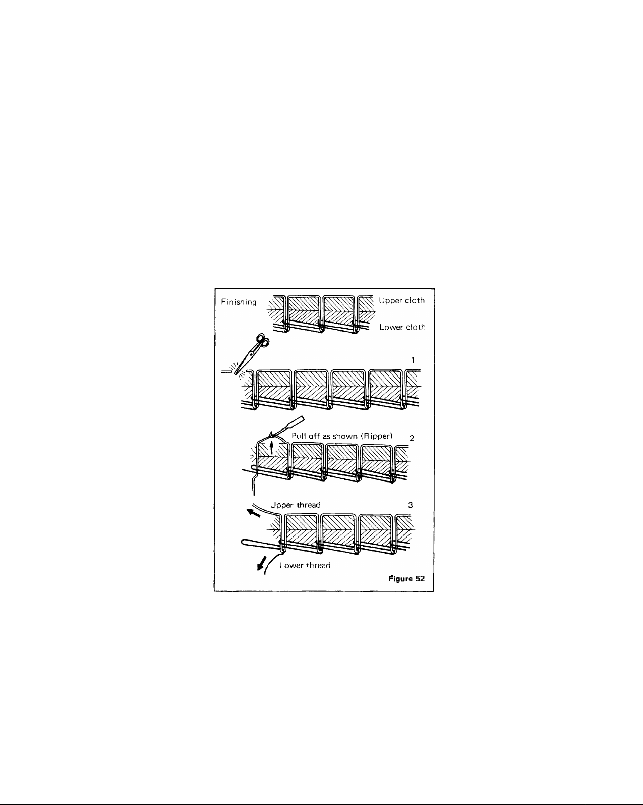
13-3 Removing stitches of double chain stitch
ing seams
When loosening seams, remove the threads in the
reverse direction of sewing as shown in Figure
52.
18
Page 22
1 4 SUPPLEMENT
Detailed list of contents
1) Machine
2) Motor
3) Controller set
4) Vinyl cover
5) Instruction booklet
6) Accessory box
(Contents)
Screw driver
Spanner (for motor bracket)
Needles
Upper knife
Tweezers
Cleaning brush
Oil
Heart-shaped driver (for adjusting stitch length)
Sewing margin gauge
Presser foot for knitted material
Net
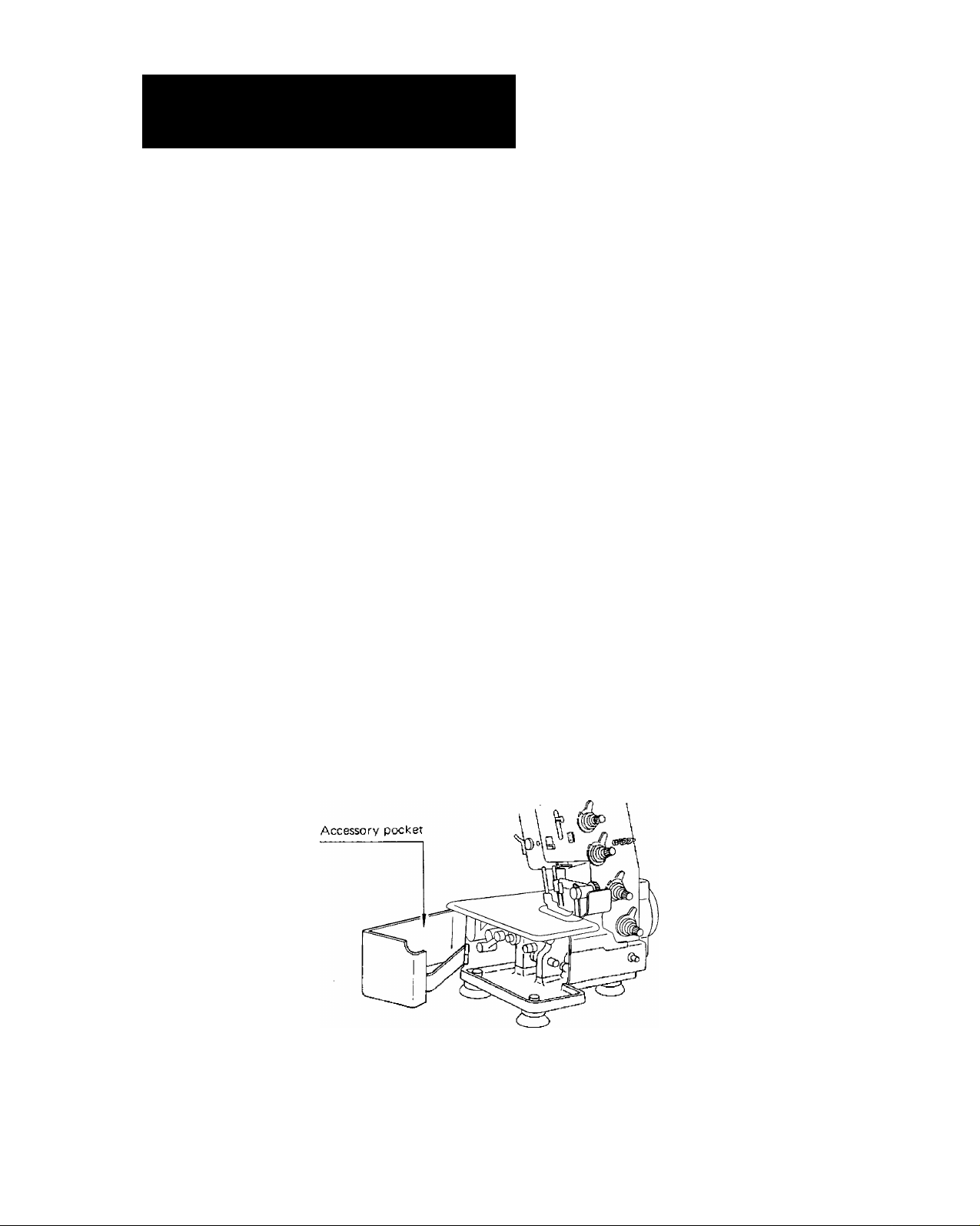
It is recommended that the pocket on the side
cover be used for storing the accessories at the
time of using the machine as shown in Figure 53.
Figure 53
1 9
Page 23
CHANGING THE CARBON BRUSHES
15
OF THE MOTOR
Two carbon brushes (in two positions) are
used for the motor on this sewing machine.
The carbon brushes should be changed according
to the following method, as they will wear
after long hours of use.
A) Period for changing carbon brushes
The carbon brushes should be changed when
they have worn too short for contact (see
carbon brush figure),
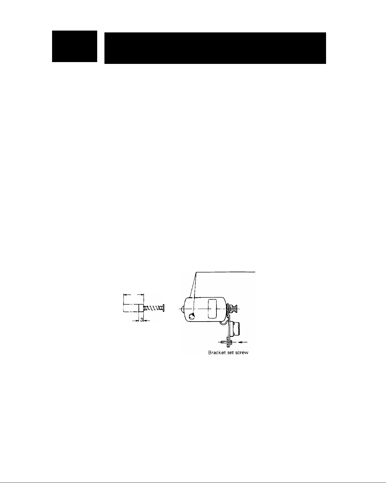
B) First remove the motor. Remove the brush
caps (see figure of motor), and replace the
brushes.
Figure of carbon brush
Brush cap (two)
10mm
The carbon brushes should be changed when
the brush section has worn down to approxi
mately 3 mm as shown in the figure.
Carbon brushes may be purchased from any
sewing machine shop or electrical appliance
shop.
Note: Special care should be taken with
regard to the aforementioned points as
failure to change the brushes may result in
sparks emitting from the motor which will
cause damage to the motor.
20
Page 24

1 0 SPECIFICATIONS
ítem Specification
Overedging width
Distance between needles 3 m/m
Stitch length {feed)
Needle bar stroke 27 m/m
Knife movement 6 m/m
Presser foot lift
Feed dog height
Needles
Number of threads
Method of lubrication
Machine dimensions Length 250 m/m x Breadth 250 m/m x Height 310 m/m
Weight of machine |
4 m/m
1 6 m/m
3.5 m/m
0.7 m/m
SINGER needle Cat. No. 2053, 90/14
4
Semi-automatic oil wick lubrication
Approximately 10 kgs (with motor and controller)
21
Page 25

TABLE SHOWING RELATIONSHIP
17
No. Type of cloth Use Type of thread
Thin cloth (organdy,
thin tricot, taffeta,
1
silk, crepe, suit lining)
Ordinary cloth
2
(cotton, tricot, linen,
satin, cloth in general)
Thick cloth (tweed,
3
denim, suit cloth)
Knitted cloth
4
(knitted goods,
knitted cloth)
BETWEEN THREAO ANO CLOTH
Double chain stitching
(straight seaming)
Overedging
Double chain stitching
Overedging
Double chain stitching
Overedging
Double chain stitching
Overedging
Cotton #80 ~ #100
Silk #80-#100
Cotton #80 ~ #100
Silk #80-#100
Cotton #60- #100
Silk #50-#100
Cotton #60-#100
Silk #50- #100
Cotton #40 — #60
Silk #40-#60
Tetron and woolly nylon
threads
Cotton #40 — #60
Silk #40-#60
Tetron and woolly nylon
threads
Cotton #40 — #50
Silk #30- #40
Tetron, woolly nylon and
transparent nylon threads
Woolly nylon and tetron
threads
♦ Very thin woollen
thread may be used
as the lower thread.
Length of stitch
2.0 m/m — 3.0 m/m
3.0 m/m — 4.0 m/m
2.0 m/m — 3.0 m/m
3.0 m/m — 4.0 m/m
2.0 m/m — 4.0 m/m
3.0 m/m — 5.0 m/m
2.0 m/m — 4.0 m/m
3.0 m/m — 5,0 m/m
22
Page 26

' t
I
''3
ip
I
m
■-
I
a
■
1
m
m
i
pa
I
\
\i
i -5
'■1
‘ilp
'i
i
im
I
■
i.
I
J
vi
1«
1
i
' s
a
, -i
. '--.i
SINGER
Printed in jcpan
(?i
 Loading...