

Sinexcel PWS2-30M-EX User Manual

Energy Storage Inverter
PWS2-30M-EX
User's Manual
Shenzhen Sinexcel Electr i c Co. , Lt d.

User’s Manual
Sinexcel PWS2-30M-EX Energy Storage Inverter
Data version: A05
Filed in: Feb 21, 2019
Applicable to: PWS2-30M-EX
Shenzhen Sinexcel Electric Co., Ltd. (“Sinexcel”) provides its customers with all-around
technical support. Users can contact local Sinexcel office or customer service center or
directly contact Sinexcel Headquarters.
Shenzhen Sinexcel Electr i c Co. , Lt d.
All rights reserved. In cas e of any content change, it shoul d be w it hout prior notice.
Shenzhen Sinexcel Electr i c Co. , Lt d.
Website: www .sinexcel.com
Add: Building 6, Area 2, Baiwangxin High-tech Industrial Park, No. 1002, Songbai Road,
Nanshan District, Shenz hen, China
Postcode: 518055
Hotline: 0755-8651-1588
Fax: 0755-8651-3100
E-mail: service@sinexcel.com

CONTENT
CHAPTER 1 OVERVIEW __________________________________________ - 1 -
1.1 MODEL DEFINITION __________________________________________________ - 1 -
1.2 ICON INTERPRETATION _______________________________________________ - 1 -
1.2.1 Icons in the manual ____________________________________________ - 1 -
1.2.2 Inverter prompt icons ___________________________________________ - 2 -
1.3 SAFETY INSTRUCTIONS ______________________________________________ - 2 -
1.3.1 Safety instructions for mechanical installation ________________________ - 3 -
1.3.2 Safety instructions for electrical connection _________________________ - 3 -
1.3.3 Safety instructions for inverter operation ____________________________ - 4 -
1.3.4 Safety instructions for maintenance and replacement _________________ - 4 -
1.3.5 Others ______________________________________________________ - 5 -
1.4 PRECAUTIONS _____________________________________________________ - 6 -
1.4.1 Personnel requirements _________________________________________ - 6 -
1.4.2 Purposes of usage _____________________________________________ - 6 -
1.4.3 Label on enclosure ____________________________________________ - 6 -
1.4.4 Notes _______________________________________________________ - 6 -
CHAPTER 2 INTRODUCTION TO ENERGY STORAGE SYSTEM __________ - 7 -
2.1 SYSTEM APPLICATION ________________________________________________ - 7 -
2.1.1 System structure diagram _______________________________________ - 7 -
2.2 OVERALL DIMENSION ________________________________________________ - 8 -
2.3 APPEARANCE _____________________________________________________ - 8 -
2.4 TECHNICAL PARAMETERS _____________________________________________ - 9 -
2.5 TECHNICAL SPECIFICATION ___________________________________________ - 10 -
2.5.1 Principle description ___________________________________________ - 10 -
2.5.2 Function description ___________________________________________ - 11 -
2.5.3 De-rating ___________________________________________________ - 12 -
CHAPTER 3 EQUIPMENT TRANSPORT , STORAGE A ND INSTALLATION __ - 15 -
3.1 TRANSPORT AND STORAGE ___________________________________________ - 15 -
3.2 INSTALLATION FLOW ________________________________________________ - 16 -
3.3 OPEN-CASE INSPECTION ____________________________________________ - 17 -
3.4 MODEL CHECK AND PREPARATION ______________________________________ - 17 -
3.5 INSTALLATION REQUIREMENTS ________________________________________ - 18 -
3.6 ELECTRICAL CONNECTION ___________________________________________ - 18 -
3.7 CHECK AFTER INST ALL A TION __________________________________________ - 25 -
3.7.1 Cable connection check ________________________________________ - 25 -
3.7.2 Electric and communication check _______________________________ - 25 -
CHAPTER 4 DEBUG A ND OPERATION _____________________________ - 28 -
4.1 STARTUP AND SHUTDOWN ___________________________________________ - 28 -

4.1.1 Check before startup __________________________________________ - 28 -
4.1.2 Startup steps ________________________________________________ - 28 -
4.1.3 Shutdown steps ______________________________________________ - 28 -
4.2 MONITORING INTERFACE INFORMATION _____________________________________ - 29 -
4.3 CONTROL METHOD ___________________________________________________ - 31 -
CHAPTER 5 COMMUNICATION MODE ______________________________ - 33 -
5.1 COMMUNICATION INTERFACE _________________________________________ - 33 -
5.1.1 RS-485 interface _____________________________________________ - 33 -
5.1.2 Ethernet interface ____________________________________________ - 33 -
5.2 BMS COMMUNICATION ______________________________________________ - 34 -
5.3 MONITORING SYSTEM STRUCTURE _____________________________________ - 34 -
CHAPTER 6 MAI NTE NA N CE ______________________________________ - 36 -
6.1 OPERATION ENVIRONMENT REQUIREMENTS _______________________________ - 36 -
6.2 ELECTRICAL AND FIXED CONNECTION INSPECTION __________________________ - 36 -
6.3 CLEARING AND CLEANING ____________________________________________ - 36 -
APPENDIXES __________________________________________________ - 37 -
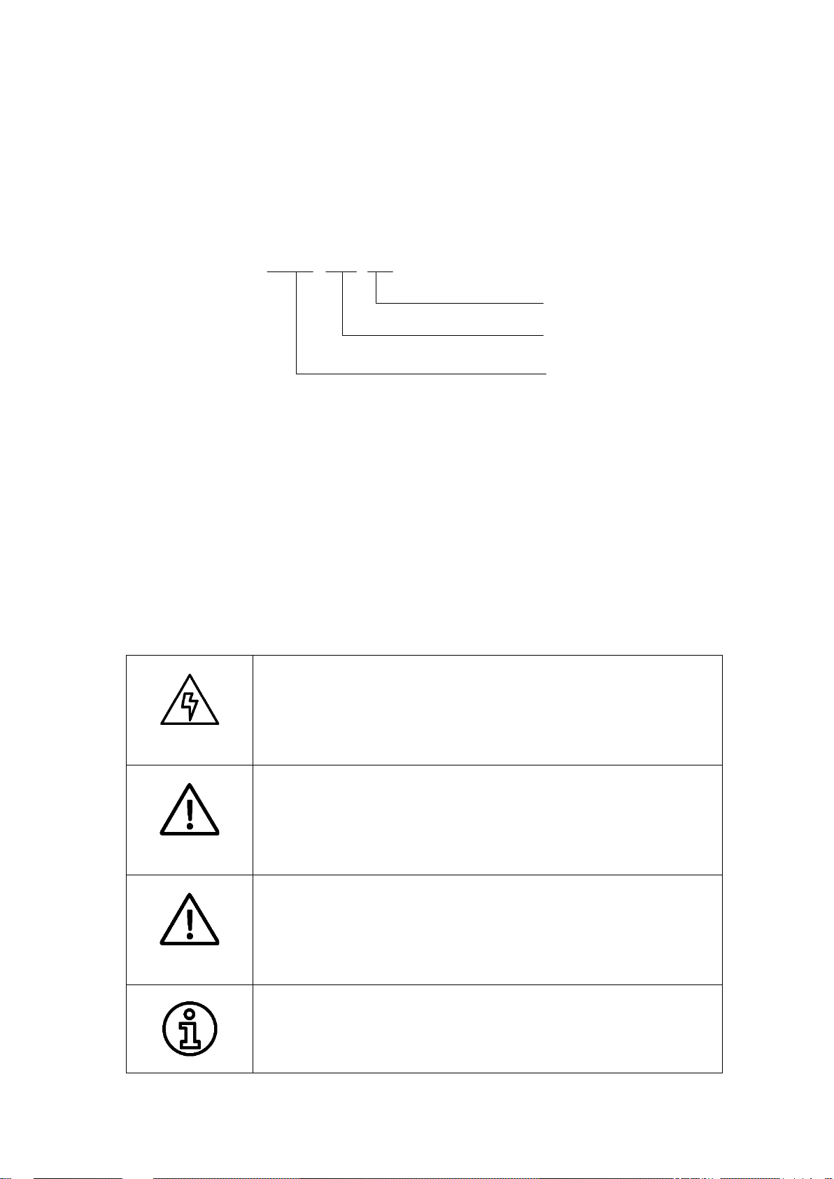
PWS2 - 30M - EX
For Europe and Australia
Rated power:30kW
M: For modular design
Wide battery voltage-supported
energy storage inverter
The WARNING icon indicates that there is a potential risk during
The CAUTION icon indicates that there is a potential risk during
Chapter 1 Overview
1.1 Model definition
The model definition of PWS2-30M-EX energy storage invert er is show n i n Fig. 1-1:
Fig. 1-1 Model definition
1.2 Icon interpretation
This user’s manual is about install ation and use of Sinexcel PWS2-30M-EX energy storage
inverter.
To ensure personal and property safety or use this product efficiently, please read this
user’s manual carefully before installation and use.
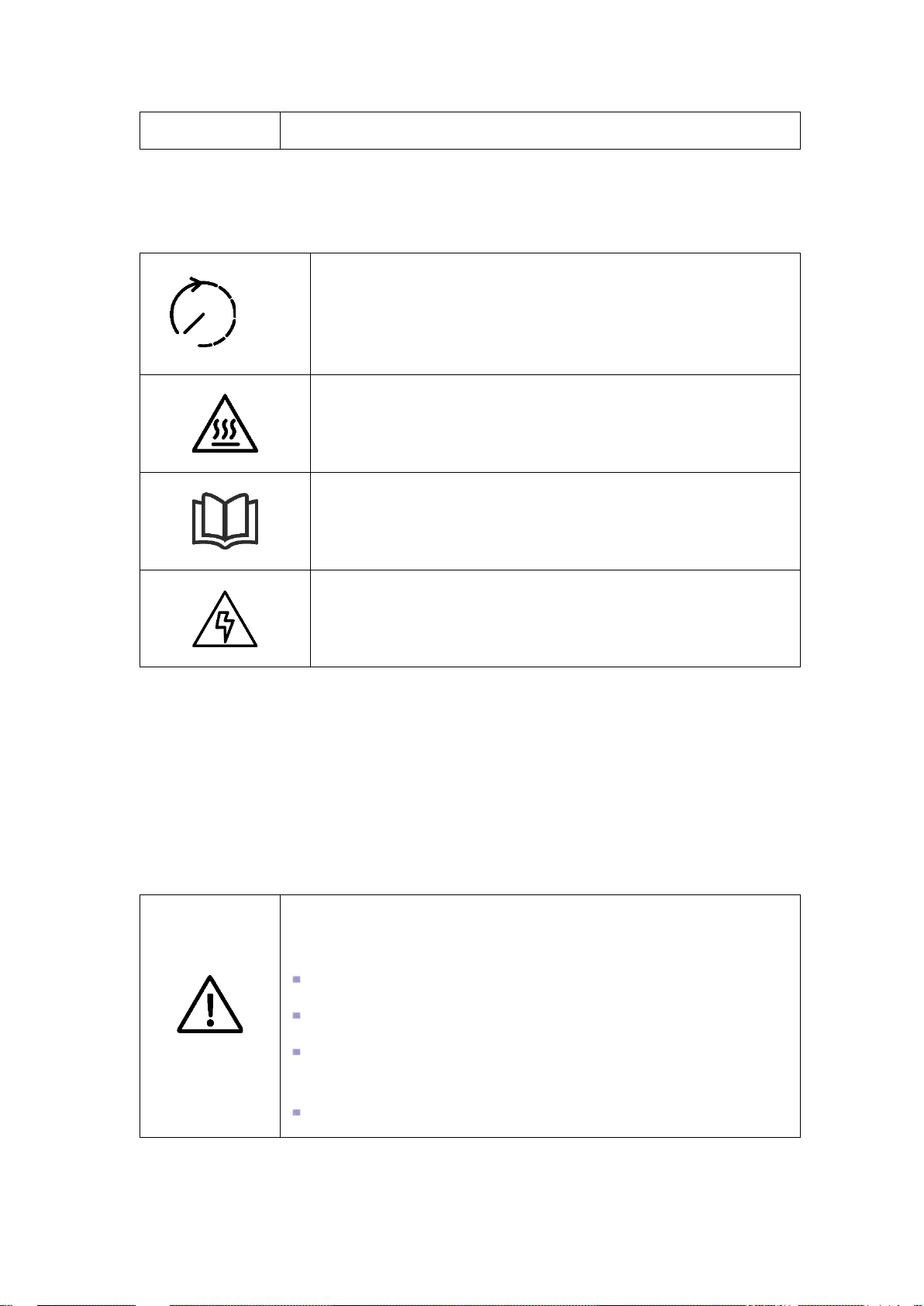
1.2.1 Icons in the manual
The following are the ex amples for icons in t his user’s manua l. Please read and und erstand
the definition of each icon.
The DANGER icon indicates that there is a safety risk during operation.
If this kind of warning information is not fol lowed, it will direct ly result in
DANGER
WARNING
a serious human casualty accident.
operation. If this kind of warning information is not followed, it might
result in a serious human c asualty accident.
operation. If this kind of warning information is not followed, it might
CAUTION
result in device damage.
The NOTE icon indicates the additional information in the manual and
a highlight and supple men t for the c ontent . It prov ides s kills an d tip s o f
product usage and can help you efficiently solve some problems in
- 1 -
by waiting for 10 minutes after inverter and power grid are
application.
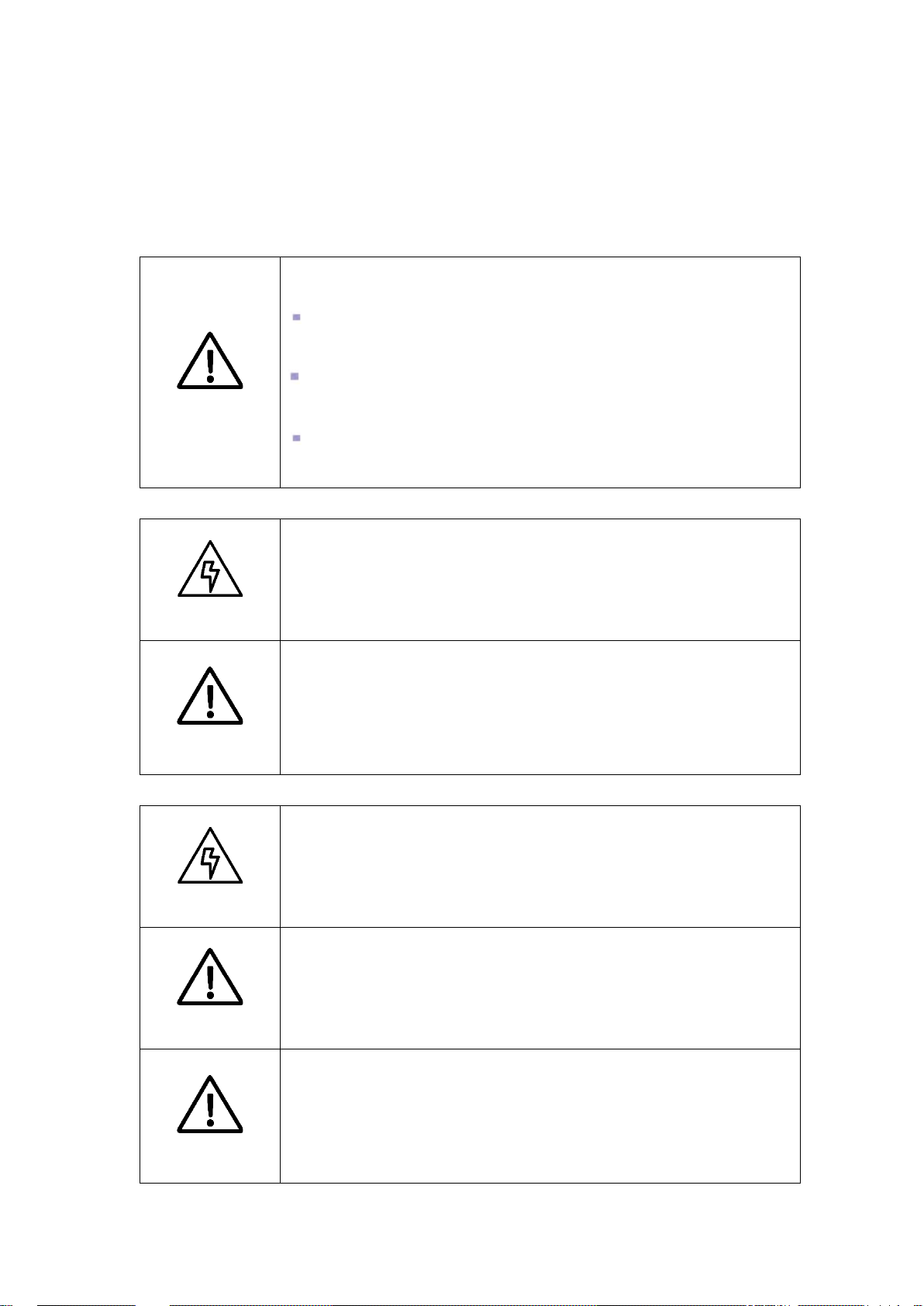
1.2.2 Inverter prompt icons
The following are the examples for icons on the inverter. Please read and understand the
definition of each icon.
This icon indicates that internal co nductive device can be touched
10min
disconnected from storag e battery.
This icon ind icates that t he inverter surface is hot dur ing operatio n.
Keep cautious. Don’t touch the inv erter surface.
This icon indicates that be fore any operat ion of the in verter, please
read this product manual carefully.
The ELECTRICAL DANGER icon indicates that only professional
and qualified personnel can carry out equipment installation and
electric operation.
1.3 Safety instructions
PWS2-30M-EX energy storage inverter is designed and tested in strict accordance with
relevant international safety standards. Its installation, trial operation, operation and
maintenance should comply with safe operation specifications of electrical and electronic
equipment. Incorrect use or wrong operation might endanger operator or a t hird par t y and
destroy the inverter or other properties. To prevent the above circumstances from
happening, the following precautions should be strictly abided by in the process of
operation and maintenance. The detailed descr iption will be provided in relevant chapter .
All installation, debugging and maintenance should be completed by
professionals. Profess ionals should:
be approved engineer by t he fact or y or its agent;
be professionally traine d;
WARNING
fully read this manual and learn about safe operation matters for
electrical and electronic equipment;
be familiar with relevant safety specification of ele ctric system.
Professionals who meet the above conditions can:
- 2 -
Removal and placement of the inverter should abide by the
Any system (equipment) damage caused by modification and
During equipment operation, the ventilation should be good. The
All electrical installations should meet national/regional electrical
(1) Install the inverter;
(2) Setup energy storage system as per customer’s requir ement;
(3) Conduct trial operation of energy storage system;
(4) Operate, debug and m aint ain energy storage system.
Equipment wrong operation might cause injury !
description in this manua l.
Improper equipment operation might cause electric shock, burn or
CAUTION
contusion.
disassembly without permission does not fa ll int o the warranty scope.
1.3.1 Safety instructions f or mec h ani cal installation
Before inverter installation, ensure that the inverter does not have any
electric connection.
DANGER
Poor ventilation for install at ion w i ll weaken the system performance!
equipment should be upr ight, and there s hould b e no strong air curr ent
CAUTION
to prevent airflow so as to ensur e t hat t he device is cooled well.
1.3.2 Safety instructions f or el ec tr i cal connection
Be careful in electric connection. There is dangerous voltage between
the two poles of storage battery. Don’t touch the metal terminal when
DANGER
CAUTION
there is no sufficient pr ot ection.
The cables used in energy storage system must be connected firmly
and with good insulation and pr oper specification.
standards;
CAUTION
Grid-tied operation can be conduct ed after per mission is obtained from
local national/regiona l ele ct r ic pow er department.
- 3 -

of the
to this device will be conducted by
injury or equipment damage. Before any operation, users should
Before power-on, please ensure that it is reliably grounded and the
grounding meets local electrical standards.
1.3.3 Safety instructions for inverter operation
Any contact with copper bar, uncovered contact spot or terminal inside
the device that is connected to the loop of power grid might result in
burning or fatal electric sh ock.
Don’t touch any terminal and conductor connected with the power
DANGER
grid.
Pay attention to any instruction and safety documents about grid
connection.
There might be an electric shock risk inside the device! When the
inverter operates or is electrified, don’t open the enclosure
inverter.
Only intact and closed cabinet can protect operator’s personal and
property safety.
Any operation related
professionals.
WARNING
Pay attention to the safety precaut ions listed in this manual and other
documents.
When AC of the inverter is loaded, DC disconnection is not allowed. If
disconnection is required, shutdown operation should be conducted
first. After the AC load isolation switch of the inverter is disconnected
and it is confirmed that there is no voltage at the AC terminal of the
inverter, DC connection can be turned off.
During inverter operation, t he ventilation duct must not be blocked.
CAUTION
1.3.4 Safety instructions for maintenance and replacement
Improper equipment m aintenanc e and operat ion m ight caus e persona l
strictly abide by the follow i ng s t eps:
DANGER
Disconnect the AC isolation switch between the power grid and the
- 4 -

contact spot, copper bar and other electric parts with body or
CAUTION
During electrical connection and maintenance, temporary warning
pasted and barriers should be set up to prevent
irrelevant personnel entering electrical connection or maintenance
Components might be caused by any contact with PCBs or other
inverter, and then turn off D C br eaker of the battery box.
Wait for at least 10 minutes until internal energy storage elements
are discharged off. During this period, don’t touch equipment termina l,
conductor.
Use detecting device to chec k and ensur e t hat ther e are no v oltage
and current on the device.
Stop irrelevant personnel from entering the maintenance site!
signs should be
area.
The inverter can be restarted only after its malfunction affecting safet y
performance is removed.
CAUTION
CAUTION
CAUTION
Power can be supplied again a fter t he inv ert er is fully disconn ected for
1 minute.
There are no serviceable parts in the inverter. If any maintenance is
required, please contact o ur aft er -sales personnel.
Don’t replace the internal elements at will. O therwise, our company will
not undertake any quality guarantee and joint liability for any losses
caused thereby.
electrostatic sensitiv e components or improper oper at ion.
Don’t touch the circuit boar ds.
Abide by electrostatic protection specifications and wear anti-static
wrist strap.
1.3.5 Others
Safety signs, warning lab el and nameplate on the inv er t er :
Must be clearly visible;
WARNING
Should not be removed or covered.
- 5 -

1.4 Precautions
1.4.1 Personnel requirements
Energy storage inverter must be debugged and maintained by the engineers designated
by the manufacturer or its agent. Otherwise, it might endanger personal safety and result
in device fault. Any damage aga inst the device ca used thereby will not fall into the warranty
scope.
1.4.2 Purposes of usage
Energy storage inverter is only used for commercial/industrial purposes, and it cannot be
used as an energy saving dev ice rel at ed to life support device.
1.4.3 Label on enclosure
The label on enclosure contains important information for safe operation to the inverter.
Don’t tear or damage it.
The label on enclosure should be clear and readable. If it is damaged or becomes vague,
please replace it.
1.4.4 Notes
To help users read this manual more conveniently, a lot of pictures are provided in this
manual. Such pictures are only used for de scription and indic ation. For detailed in formation,
please refer to the product itself.
- 6 -

Chapter 2 Introduction to energy storage system
Energy Management
System
Intelligent Power
Distribution Unit
or manual sw itch
Grid
Ethernet/RS-485
Energy Storage Inverter
Battery and
Industrial Load
Battery Managem ent
System
RS-485
Communication
2.1 System application
As shown in Fig. 2-1, the energy storag e sy ste m set up by PWS2-30M-EX is composed of
battery (pack), energy stor age invert er, intelligent (or manual) power distribution unit, EMS
and BMS. Battery pack is conn ected t o ener gy storage inv ert er. Energy storage inverter is
connected with the load and power grid through intelligent (or manual) power distribution
unit. Energy storage inverter communicates with EMS through Ethernet interface (or RS485 interface) to indirectly control charging and discharging of battery pack. EMS
communicates with energy storage inverter, BMS and/or intelligent electric meter through
RS-485 interface to d isp atch the energy of an energy storage system.
2.1.1 System structure diagram
The structure diagram of energy storage system is shown below. PWS2-30M-EX energy
storage inverter pushes t he dat a to EMS or other host syst ems in re al time.
The Intelligent power distribution unite is a remote controllable disconnector. A manual
switch can also work. This component is used to isolate the grid when the system needs
to run in off-grid mode.
Fig. 2-1 Structure of energy storage system
- 7 -
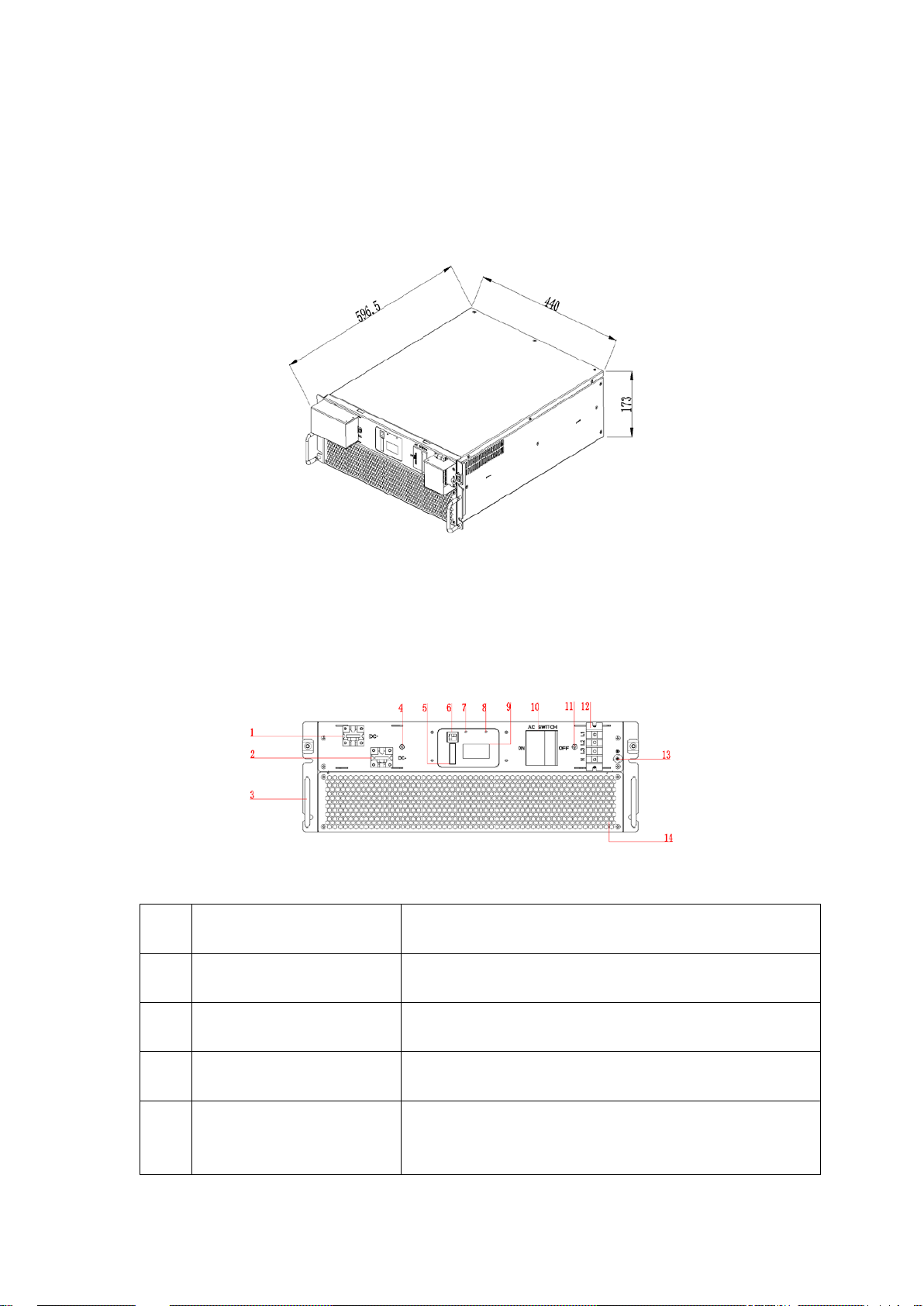
2.2 Overall dimension
Overall dimension of PWS2-30M-EX is shown in Fig.2-2.
Fig. 2-2 Overall dimension of PWS2-30M-EX (unit: mm)
2.3 Appearance
The appearance of PWS2-30M-EX is shown in Fig.2-3.
Fig. 2-3 Appearance of front side of PWS2-30M-EX
SN Name Description
1 Positive DC port To connect positive power cables to the battery cabinet
2 Negative DC port To connect negative power cables to the bat t er y cabinet
3 Knob Pulling module can’t be used for bearing
DC protection shell fixing
4
point
For DC terminal protection case fixing
- 8 -

5 Communication interfaces Including RS-485, EPO
6 Internet port Ethernet
7 Running lights Lights on during normal o per at ion
8 Fault indicator Lights on during abnormal running
9 Monitor screen Display monitoring content
10 AC breaker
11
AC protection shell fixi ng
point
Safety device to connect or disconnect the current in
AC port.
For AC termin al protection case fixing
12 AC port To connect AC power cables
13 Ground port To connect ground protection point.
14 Air outlet Ventilation duct exit for heat dissipation
2.4 Technical parameters
Technical parameters of PWS2-30M-EX energy st or age inverter:
Table 2-1 Technical parameters
Product Model PWS2-30M-EX
DC PORT - BATTERY
Battery Voltage Range 200~750V
DC.Max Current 90A
DC.Max Pow er 33kW
AC GRID-TIE PARAMETER
Rated Output Power 30kW
Rated Voltage 400V
Voltage Range -20%~+15%
Rated Frequency 50Hz
Frequency Range -2.5~+1.5Hz
AC.Rated Current 43.3A
Output THDi
Power Factor 0 leading~0 lagging
AC OFF-GRID PARAMETER
≤3%
- 9 -

Voltage 380/400V
Voltage Adjustable Range ±5%
Frequency 50Hz
Output THDu
Output THDu
SYSTEM PARAMETER
Peak Efficiency 97.1%
Wiring Mode 3P3W+PE, 3P4W+PE
Isolation Mode No-isolation
Cooling
Noise 60dB
Working Temp.
IP Degree IP20
Max Elevation 4000M(de-rating in case of exceeding 2,000m)
Humidity Range 0~95%
Size (W*D*H) 440*550*173mm
Weight 30kg
Type of battery Lithium battery, lead-acid battery
COMMUNICATION
Display LCD Screen
Communication Protocol Modbus TCP/IP, MESA
Communication Socket
-20℃~60℃(de-rating in case of exceeding 45°C)
≤1%(Linear load)
≤5%(Nonlinear load)
Forced air cooling with
replaceable fan module
Ethernet、RS485
2.5 Technical specification
2.5.1 Principle description
There are three operation modes: grid-tied discharging, char ging and off-grid discharging.
When the battery volt age connected to PWS2-30M-EX is within the preset normal voltage
range, the inverter can operate under grid-tied discharging, charging and off-grid
discharging. If the inverter is in discharging state, the DC power supply of the battery can
be inverted into 3-phase AC power supply. If the inverter is in charging state, the 3-phase
AC power energy of the pow er gr id ca n be stored into battery (pac k).
The protection circuit of the inverter is used to ensure safe operation of the inverter and
operators’ safety.
Energy storage inverter without built-in isolation tran sform er.
If the capacity of the ener gy storage device does not meet t he demand,
CAUTION
multiple parallel connections can be made. Each inverter is equipped
with a suitable battery capacity on the DC side and the AC side is
- 10 -

connected to the grid in parallel.
2.5.2 Function description
The functions of PWS2-30M-EX are as follows:
Grid-tied discharging: The inverter is in inver ting state, conv erts DC into AC that meets the
requirement of power grid department in installation region, and feeds the energy back to
the power grid.
Grid-tied charging: The inverter is i n rectification state and tr ansmits 3-phase AC to charge
the battery (pack) by the set char ging mode.
Off-grid discharging: The inverter is in inverting state, converts DC into AC that meets the
requirement of power gr id depart ment in in stal lation r egi on, an d prov id es pow er supp ly for
3-phase load in the micro-grid.
Data storage and display: Storage and operation informatio n, oper at io n r ec ord and failure
record are displayed on the LC D scr een.
Communication function:
Standard RS-485 interface can be connected with monitoring device such as EMS,
BMS.
Standard Ethernet interface is used to communicate with upper computer to realize
such functions as remote cont r ol a nd r emote software upgradin g.
Reactive power configuration: Regulate the reactive power of the storage system.
FVRT: frequency/voltage ride-through, this function can be enabled or disabled, for
more information, please refer to UL1741 Supplement A or other similar rules about
Utility-Inter active Distribute Generators.
Soft-Start/Reconnection ramp rate: This function will apply when system suspend
happens caused by utility voltage abnor mal, and reconnect after utility r estore normal.
The default value is 2, twice of rated power per second, which means within 0.5
seconds the system restores to full output.
Anti-Islanding: enable or disable anti-island ing function. For more informati on, please
refer to UL1741 Supple ment A or other similar ru les about Uti lity -Interact ive D ist ribut e
Generators.
Volt/Watt: Available when activated and operating in discharge mode. When the
actual voltage is above the point, the active power will be regu lated with the ramp rat e.
The ramp rate is defined as multiple of set active power per 1% of rated voltage that
above the Volt/Wat t point.
Volt/VAR: Available when activated and operating in discharge mode. In this mode,
Reactive power as a function of grid voltage. In Volt/Var mode, the Q configuration is
- 11 -
 Loading...