

Sinexcel PWS2-30K-NA User Manual

PWS2-30K-NA
Energy Storage Inverter
User's Manual
Shenzhen Sinexcel Electric Co., Ltd.

User’s Manual
Sinexcel PWS2-30K-NA Energy Storage Inverter
Data version: A00
Filed in: March 15, 2017
Applicable to: PWS2-30K-NA
Shenzhen Sinexcel Electric Co., Ltd. (“Sinexcel”) provides its customers with all-around
technical support. Users can contact local Sinexcel office or customer service center or
directly contact Sinexcel Headquarters.
Shenzhen Sinexcel Electric Co., Ltd.
All rights reserved. In case of any content change, it should be without prior notice.
Shenzhen Sinexcel Electric Co., Ltd.
Website: www.sinexcel.com
Add: Building 6, Area 2, Baiwangxin High-tech Industrial Park, No. 1002, Songbai Road,
Nanshan District, Shenzhen, China
Postcode: 518055
Hotline: 0755-8651-1588
Fax: 0755-8651-3100
E-mail: service@sinexcel.com

CONTENT
CHAPTER 1 OVERVIEW ____________________________________________________ - 1 -
1.1 MODEL DEFINITION __________________________________________________________ - 1 -
1.2 ICON INTERPRETATION _________________________________________________________ - 1 -
1.2.1 Icons in the manual _____________________________________________________ - 1 -
1.2.2 Inverter prompt icons ____________________________________________________ - 2 -
1.3 SAFETY INSTRUCTIONS ________________________________________________________ - 2 -
1.3.1 Safety instructions for mechanical installation ________________________________ - 3 -
1.3.2 Safety instructions for electrical connection __________________________________ - 3 -
1.3.3 Safety instructions for inverter operation ____________________________________ - 4 -
1.3.4 Safety instructions for maintenance and replacement __________________________ - 5 -
1.3.5 Others ________________________________________________________________ - 6 -
1.4 PRECAUTIONS ______________________________________________________________ - 6 -
1.4.1 Personnel requirements __________________________________________________ - 6 -
1.4.2 Purposes of usage _______________________________________________________ - 6 -
1.4.3 Label on enclosure ______________________________________________________ - 6 -
1.4.4 Notes _________________________________________________________________ - 6 -
CHAPTER 2 INTRODUCTION TO ENERGY STORAGE SYSTEM _______________________ - 7 -
2.1 SYSTEM APPLICATION _________________________________________________________ - 7 -
2.1.1 System structure diagram ________________________________________________ - 7 -
2.1.2 Adaptive power grid type _________________________________________________ - 8 -
2.2 OVERALL DIMENSION _________________________________________________________ - 8 -
2.3 APPEARANCE _______________________________________________________________ - 9 -
2.4 TECHNICAL PARAMETERS ______________________________________________________ - 10 -
2.5 TECHNICAL SPECIFICATION _____________________________________________________ - 14 -
2.5.1 Principle description ____________________________________________________ - 14 -
2.5.2 Function description ____________________________________________________ - 14 -
2.5.3 De-rating _____________________________________________________________ - 16 -
CHAPTER 3 EQUIPMENT TRANSPORT, STORAGE AND INSTALLATION ______________ - 19 -
3.1 TRANSPORT AND STORAGE _____________________________________________________ - 19 -
3.2 INSTALLATION FLOW _________________________________________________________ - 20 -
3.3 OPEN-CASE INSPECTION ______________________________________________________ - 21 -
3.4 MODEL CHECK AND PREPARATION ________________________________________________ - 22 -
3.5 INSTALLATION REQUIREMENTS __________________________________________________ - 23 -
3.6 INSTALLATION _____________________________________________________________ - 25 -
3.7 ELECTRICAL CONNECTION _____________________________________________________ - 28 -
3.8 CHECK AFTER INSTALLATION ____________________________________________________ - 33 -
3.8.1 Cable connection check _________________________________________________ - 33 -
3.8.2 Electric and communication check _________________________________________ - 34 -
3.9 INSTALLATION OF BOTTOM COVER ________________________________________________ - 34 -

CHAPTER 4 DEBUG AND OPERATION ________________________________________ - 36 -
4.1 STARTUP AND SHUTDOWN _____________________________________________________ - 36 -
4.1.1 Check before startup____________________________________________________ - 36 -
4.1.2 Startup steps __________________________________________________________ - 36 -
4.1.3 Shutdown steps ________________________________________________________ - 36 -
4.2 POWER REGULATION _________________________________________________________ - 37 -
CHAPTER 5 HMI AND OPERATIONS _________________________________________ - 38 -
5.1 DESCRIPTION ______________________________________________________________ - 38 -
5.2 WELCOME INTERFACE FOR STARTUP ______________________________________________ - 38 -
5.3 HOME PAGE ______________________________________________________________ - 39 -
5.3.1 Main menu ___________________________________________________________ - 39 -
5.4 ENERGY _________________________________________________________________ - 39 -
5.4.1 AC information ________________________________________________________ - 39 -
5.4.2 Battery information ____________________________________________________ - 40 -
5.4.3 Graph display _________________________________________________________ - 41 -
5.5 RECORDS ________________________________________________________________ - 41 -
5.6 CONTROL PARAMETER ________________________________________________________ - 42 -
5.7 SETTINGS ________________________________________________________________ - 44 -
5.7.1 Interface of battery parameters ___________________________________________ - 44 -
5.7.2 HMI parameters _______________________________________________________ - 46 -
5.7.3 Debug interface _______________________________________________________ - 47 -
5.7.4 Hardware parameters __________________________________________________ - 47 -
5.8 INVERTER INFORMATION ______________________________________________________ - 47 -
CHAPTER 6 COMMUNICATION MODE _______________________________________ - 49 -
6.1 COMMUNICATION INTERFACE ___________________________________________________ - 49 -
6.1.1 RS-485 interface _______________________________________________________ - 49 -
6.1.2 Ethernet interface ______________________________________________________ - 49 -
6.2 BMS COMMUNICATION ______________________________________________________ - 50 -
6.3 MONITORING SYSTEM STRUCTURE _______________________________________________ - 50 -
CHAPTER 7 MAINTENANCE _______________________________________________ - 52 -
7.1 OPERATION ENVIRONMENT REQUIREMENTS _________________________________________ - 52 -
7.2 ELECTRICAL AND FIXED CONNECTION INSPECTION _____________________________________ - 52 -
7.3 CLEARING AND CLEANING _____________________________________________________ - 52 -
APPENDIXES ___________________________________________________________ - 53 -

PWS2 - 30K - NA
For North America
Rated power:30kW
Wide battery voltage-supported
energy storage inverter
DANGER
The DANGER icon indicates that there is a safety risk during operation.
If this kind of warning information is not followed, it will directly result in
a serious human casualty accident.
WARNING
The WARNING icon indicates that there is a potential risk during
operation. If this kind of warning information is not followed, it might
result in a serious human casualty accident.
CAUTION
The CAUTION icon indicates that there is a potential risk during
operation. If this kind of warning information is not followed, it might
result in device damage.
The NOTE icon indicates the additional information in the manual and
a highlight and supplement for the content. It provides skills and tips of
product usage and can help you efficiently solve some problems in
Chapter 1 Overview
1.1 Model definition
The model definition of PWS2-30K-NA energy storage inverter is shown in Fig. 1-1:
Fig. 1-1 Model definition
1.2 Icon interpretation
This user’s manual is about installation and use of Sinexcel PWS2-30kW energy storage
inverter.
To ensure personal and property safety or use this product efficiently, please read this
user’s manual carefully before installation and use.
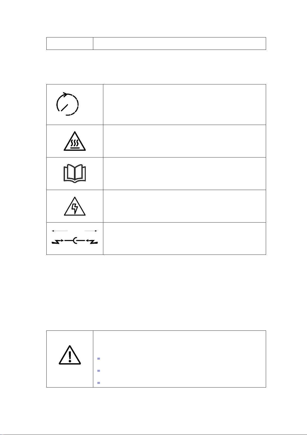
1.2.1 Icons in the manual
The following are the examples for icons in this user’s manual. Please read and understand
the definition of each icon.
- 1 -
application.
10min
This icon indicates that internal conductive device can be touched
by waiting for 10 minutes after inverter and power grid are
disconnected from storage battery.
This icon indicates that the inverter surface is hot during operation.
Keep cautious. Don’t touch the inverter surface.
This icon indicates that before any operation of the inverter, please
read this product manual carefully.
The ELECTRICAL DANGER icon indicates that only professional
and qualified personnel can carry out equipment installation and
electric operation.
STOP!
The STOP icon indicates that when the inverter is running,
disconnection is not allowed. Disconnection operation can be
conducted after the inverter is shut down.
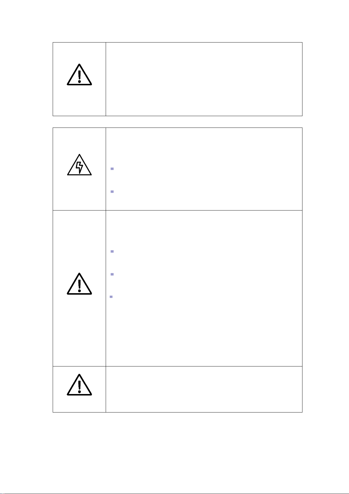
WARNING
All installation, debugging and maintenance should be completed by
professionals. Professionals should:
be approved engineer by the factory or its agent;
be professionally trained;
fully read this manual and learn about safe operation matters for
1.2.2 Inverter prompt icons
The following are the examples for icons on the inverter. Please read and understand the
definition of each icon.
1.3 Safety instructions
PWS2-30K-NA energy storage inverter is designed and tested in strict accordance with
relevant international safety standards. Its installation, trial operation, operation and
maintenance should comply with safe operation specifications of electrical and electronic
equipment. Incorrect use or wrong operation might endanger operator or a third party and
destroy the inverter or other properties. To prevent the above circumstances from
happening, the following precautions should be strictly abided by in the process of
operation and maintenance. The detailed description will be provided in relevant chapter.
- 2 -

electrical and electronic equipment;
be familiar with relevant safety specification of electric system.
CAUTION
Equipment wrong operation might cause injury!
Removal and placement of the inverter should abide by the
description in this manual.
Improper equipment operation might cause electric shock, burn or
contusion.
Any system (equipment) damage caused by modification and
disassembly without permission does not fall into the warranty scope.
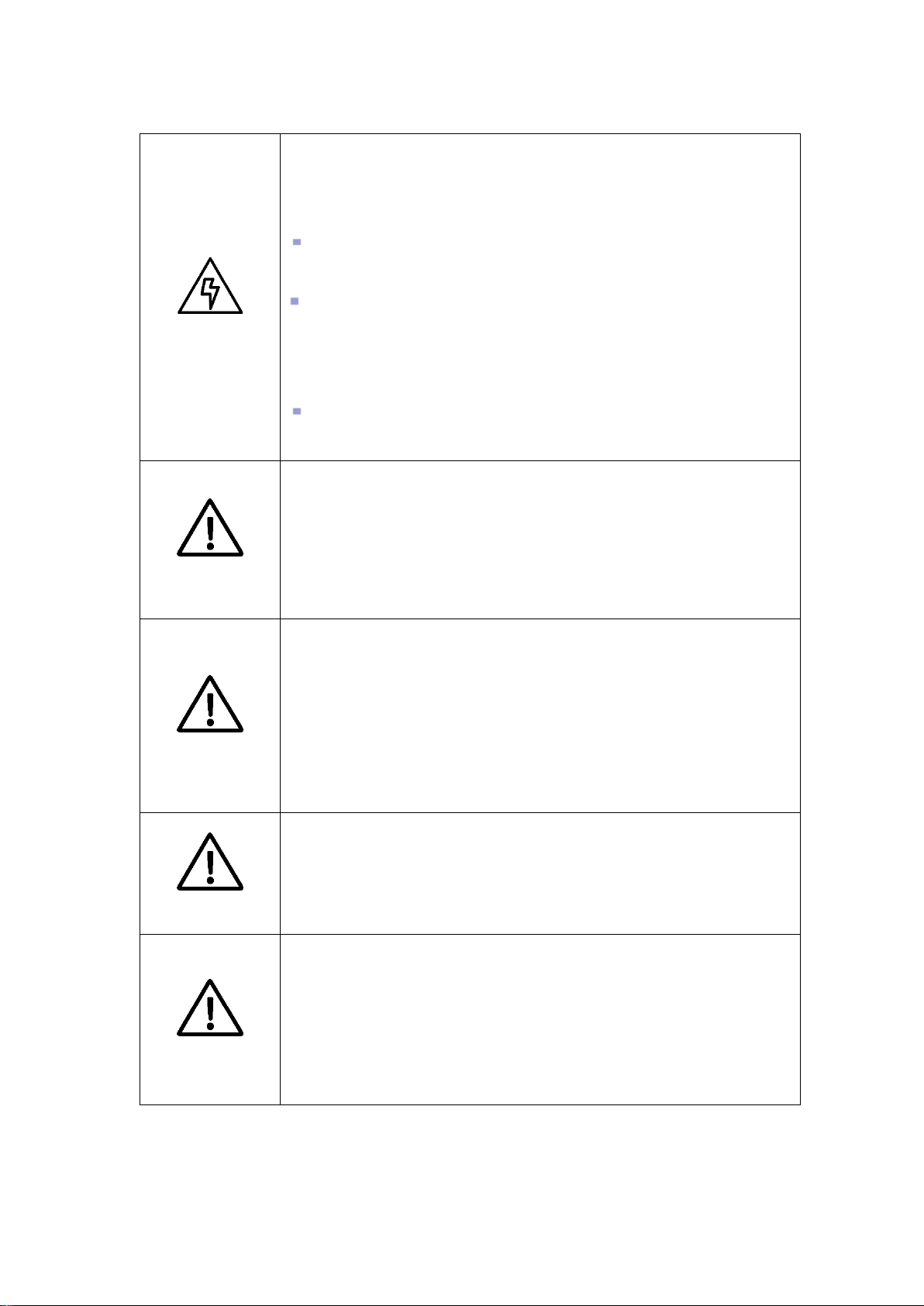
DANGER
Before inverter installation, ensure that the inverter does not have any
electric connection.
CAUTION
Poor ventilation for installation will weaken the system performance!
During equipment operation, the ventilation should be good. The
equipment should be upright, and there should be no strong air current
to prevent airflow so as to ensure that the device is cooled well.
DANGER
Be careful in electric connection. There is dangerous voltage between
the two poles of storage battery. Don’t touch the metal terminal when
there is no sufficient protection.
CAUTION
The cables used in energy storage system must be connected firmly
and with good insulation and proper specification.
Professionals who meet the above conditions can:
(1) Install the inverter onto the wall;
(2) Setup energy storage system as per customer’s requirement;
(3) Conduct trial operation of energy storage system;
(4) Operate, debug and maintain energy storage system.
1.3.1 Safety instructions for mechanical installation
1.3.2 Safety instructions for electrical connection
- 3 -
CAUTION
All electrical installations should meet national/regional electrical
standards;
Grid-tied operation can be conducted after permission is obtained from
local national/regional electric power department.
Before power-on, please ensure that it is reliably grounded and the
grounding meets local electrical standards.
DANGER
Any contact with copper bar, uncovered contact spot or terminal inside
the device that is connected to the loop of power grid might result in
burning or fatal electric shock.
Don’t touch any terminal and conductor connected with the power
grid.
Pay attention to any instruction and safety documents about grid
connection.
WARNING
There might be an electric shock risk inside the device! When the
inverter operates or is electrified, don’t open the enclosure of the
inverter.
Only intact and closed cabinet can protect operator’s personal and
property safety.
Any operation related to this device will be conducted by
professionals.
Pay attention to the safety precautions listed in this manual and other
documents.
When AC of the inverter is loaded, DC disconnection is not allowed. If
disconnection is required, shutdown operation should be conducted
first. After the AC load isolation switch of the inverter is disconnected
and it is confirmed that there is no voltage at the AC terminal of the
inverter, DC connection can be turned off.
CAUTION
During inverter operation, the ventilation duct must not be blocked.
1.3.3 Safety instructions for inverter operation
- 4 -
DANGER
Improper equipment maintenance and operation might cause personal
injury or equipment damage. Before any operation, users should
strictly abide by the following steps:
Disconnect the AC isolation switch between the power grid and the
inverter, and then turn off DC breaker of the battery box.
Wait for at least 10 minutes until internal energy storage elements
are discharged off. During this period, don’t touch equipment terminal,
contact spot, copper bar and other electric parts with body or
conductor.
Use detecting device to check and ensure that there are no voltage
and current on the device.
CAUTION
Stop irrelevant personnel from entering the maintenance site!
During electrical connection and maintenance, temporary warning
signs should be pasted and barriers should be set up to prevent
irrelevant personnel entering electrical connection or maintenance
area.
CAUTION
The inverter can be restarted only after its malfunction affecting safety
performance is removed.
Power can be supplied again after the inverter is fully disconnected for
1 minute.
There are no serviceable parts in the inverter. If any maintenance is
required, please contact our after-sales personnel.
CAUTION
Don’t replace the internal elements at will. Otherwise, our company will
not undertake any quality guarantee and joint liability for any losses
caused thereby.
CAUTION
Components might be caused by any contact with PCBs or other
electrostatic sensitive components or improper operation.
Don’t touch the circuit boards.
Abide by electrostatic protection specifications and wear anti-static
wrist strap.
1.3.4 Safety instructions for maintenance and replacement
- 5 -

WARNING
Safety signs, warning label and nameplate on the inverter:
Must be clearly visible;
Should not be removed or covered.
1.3.5 Others
1.4 Precautions
1.4.1 Personnel requirements
Energy storage inverter must be debugged and maintained by the engineers designated
by the manufacturer or its agent. Otherwise, it might endanger personal safety and result
in device fault. Any damage against the device caused thereby will not fall into the warranty
scope.
1.4.2 Purposes of usage
Energy storage inverter is only used for commercial/industrial purposes, and it cannot be
used as an energy saving device related to life support device.
1.4.3 Label on enclosure
The label on enclosure contains important information for safe operation to the inverter.
Don’t tear or damage it.
The label on enclosure should be clear and readable. If it is damaged or becomes vague,
please replace it.
1.4.4 Notes
To help users read this manual more conveniently, a lot of pictures are provided in this
manual. Such pictures are only used for description and indication. For detailed information,
please refer to the product itself.
- 6 -
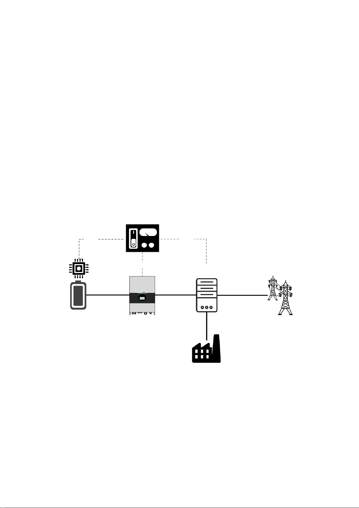
Chapter 2 Introduction to energy storage system
Energy Management
System
Intelligent Power
Distribution Unit
Grid
Ethernet/RS-485
Energy Storage Inverter
Battery and
Industrial Load
Battery Management
System
RS-485
RS-485
2.1 System application
As shown in Fig. 2-1, the energy storage system set up by PWS2-30K-NA is composed of
battery (pack), energy storage inverter, intelligent power distribution unit, EMS and BMS.
Battery pack is connected to energy storage inverter. Energy storage inverter is connected
with the load and power grid through intelligent power distribution unit. Energy storage
inverter communicates with EMS through Ethernet interface (or RS-485 interface) to
indirectly control charging and discharging of battery pack. EMS communicates with
energy storage inverter, BMS and/or intelligent electric meter through RS-485 interface to
dispatch the energy of an energy storage system.
2.1.1 System structure diagram
The structure diagram of energy storage system is shown below. PWS2-30K-NA energy
storage inverter pushes the data to EMS or other host systems in real time.
Fig. 2-1 Structure of energy storage system
- 7 -
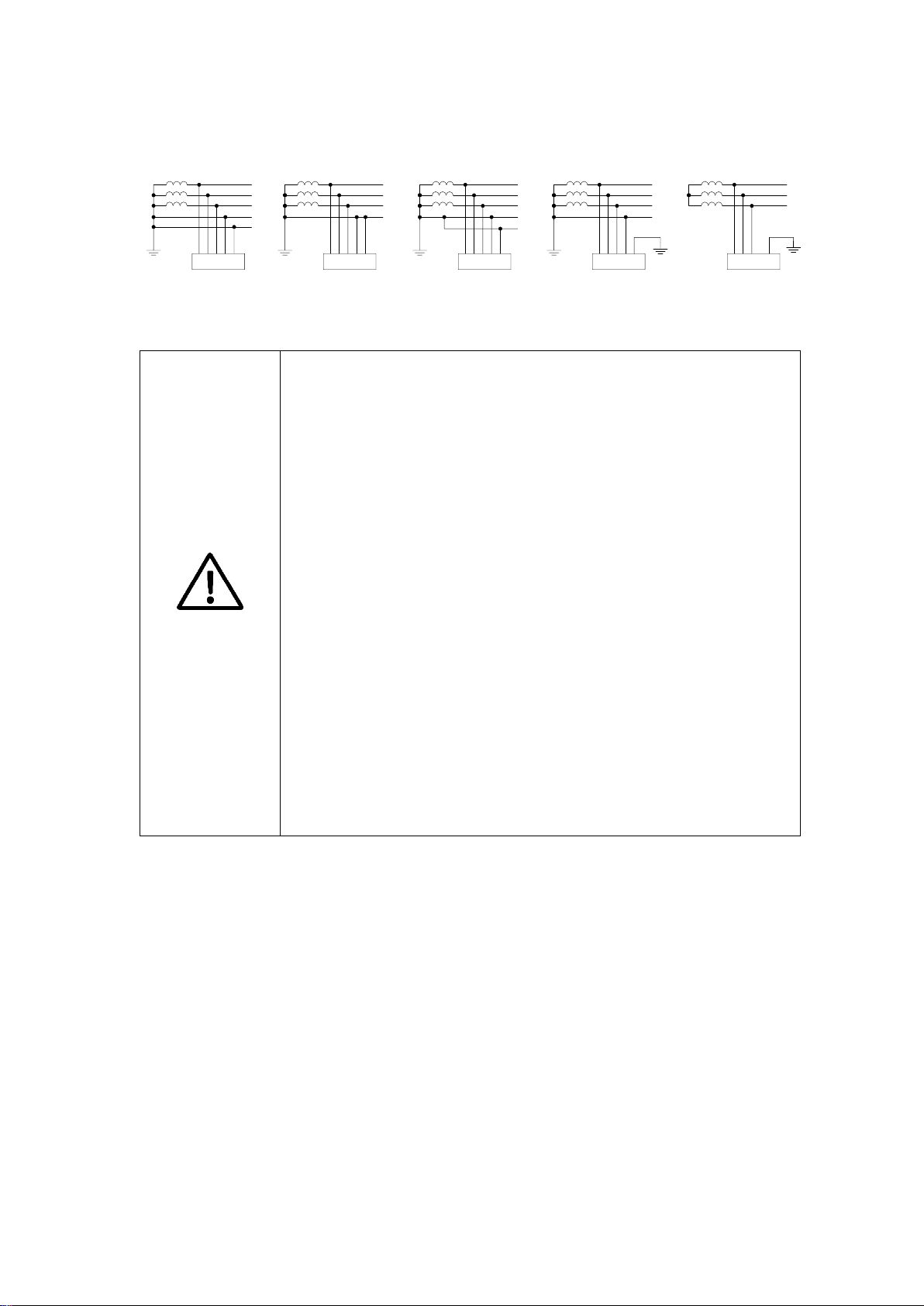
2.1.2 Adaptive power grid type
PWS2-30K
L1
L2
L3
N
PE
Transformer
TN-S
PWS2-30K
L1
L2
L3
NPE
TN-C
PE
PE
PWS2-30K
L1
L2
L3
N
PE
TN-C-S
PE
PWS2-30K
L1
L2
L3
N
TT
PE
PWS2-30K
L1
L2
L3
IT
PE
Transformer
Transformer Transformer Transformer
CAUTION
VERY IMPORTANT INFORMATION
THERE IS NO ISOLATION TRANSFORMER IN THE ENERGY
STORAGE INVERTER OF THIS MODEL.
THE AC PORT OF ENERGY STORAGE INVERTER CANNOT BE
DIRECTLY CONNECTED WITH SINGLE PHASE LOAD. IF SINGLE
PHASE LOAD IS REQUIRED, IT SHOULD BE CONNECTED
THROUGH AN ISOLATION TRANSFORMER.
IN GRID INTERACTIVE APPLICATION, IF THE CAPACITY OF
ENERGY STORAGE INVERTER DOES NOT MEET THE DEMAND,
PARALLEL CONNECTION OF MULTIPLE INVERTERS CAN BE
CONDUCTED. SEPARATE STORAGE BATTERIES WITH PROPER
CAPACITY SHALL BE EQUIPPED FOR EACH INVERTER IN DC
PORT. THE DEVICES CAN BE CONNECTED TO THE POWER GRID
IN PARALLEL ON AC PORT.
THE DC PORT OF TWO OR MORE ENERGY STORAGE
INVERTERS SHOULD NOT BE PARALLELED ON ONE SAME
BATTERY PACK/MODULE.
Fig. 2-2 Adaptive power grid type
2.2 Overall dimension
Overall dimension of PWS2-30K-NA is shown in Fig. 2-3.
- 8 -
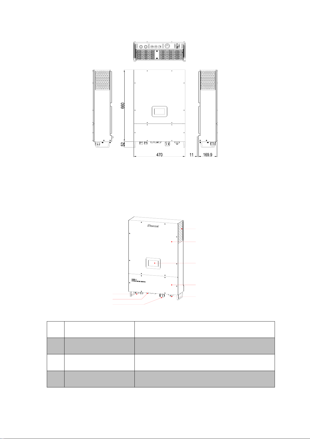
Fig. 2-3 Overall dimension of PWS2-30K-NA (unit: mm)
SN
Name
Description
1
DC port
To connect power cables to the battery cabinet
2
Communication interfaces
Including Ethernet, RS-485, R-EPO
3
AC port
AC wiring terminal for gird and AC load
8
7
6
5
4
1
2
3
2.3 Appearance
The appearance of PWS2-30K-NA is shown in Fig. 2-4.
Fig. 2-4 Appearance of front side of PWS2-30K-NA
- 9 -

4
AC switch
Safety device to connect or disconnect the current in
AC port.
5
Bottom cover
Used to cover the connecting terminals of cables under
the case.
6
HMI
Human-machine interface which is used to set
parameters of energy storage inverter and read inverter
operation information.
7
Upper panel
Case cover 8 Air outlet
Ventilation duct exit for heat dissipation
DC port
DC voltage range
200V~750V(350~750V Full Load)
Max. DC current
90A
Max. DC power
33kW
Fig. 2-5 Appearance of back side of PWS2-30K-NA
2.4 Technical parameters
Technical parameters of PWS2-30K-NA energy storage inverter:
Table 2-1 Technical parameters
- 10 -

DC voltage
accuracy
≤1%
Charge and
discharge mode
3-phase charging (constant powerconstant voltagetrickle
current); constant current discharging, constant power discharging
AC port (grid-tied mode)
Rated output
power
30kW
Rated grid voltage
480V
Grid voltage range
-12%~+10%
Rated grid
frequency
60Hz
Range of grid
frequency
±2.5Hz
Max. input short
circuit current
200A
Max. output fault
current and
duration
200A(200ms)
Max. output
overcurrent
protection
300A
Rated AC current
36.1A
Synchronization
in-rush current
30A
Trip limit and trip
time accuracy
5%
Output THDi
≤3%
Grid-tied power
0.8 leading~0.8 lagging (listed)
- 11 -

factor
0 leading~0 lagging (actual)
AC port (off-grid mode)
Off-grid AC
voltage
480V
Off-grid AC
voltage range
±5%
Off-grid AC
frequency
60Hz
Off-grid output
voltage stabilizing
accuracy
≤1%
Off-grid output
frequency
accuracy
±0.1Hz
Off-grid THDu
≤1% (linear load)
≤5% (nonlinear load)
Output overload
capacity
105%~115% 10min
115%~125% 1min
125%~150% 200ms
System parameters
Max. efficiency
97.5%
Protection
System protection: over-temperature, AC overvoltage and undervoltage, AC over frequency and under frequency, AC inverted
sequence, fan fault, relay fault, output overload and leakage current
protection
Optional safety protection conditions: upper and lower limit of AC
voltage protection, upper and lower limit of frequency protection,
upper and lower battery voltage and voltage of battery EOD
- 12 -

Installation mode
Wall-mounted
Wiring mode
3-phase +N+PE
Isolation mode
Non-isolated
Cooling mode
Fan cooling
Standby self-
power
consumption
<20W
Noise
≤60dB
Temperature
range
-20℃~60℃ (de-rating in case of exceeding 45°C)
Enclosure
CLASS I/NEMA1(IP32)
Altitude
4,000m (de-rating in case of exceeding 2,000m)
Humidity
0~95%
Dimension
470mm×660mm×170mm
Weight
43kg
Display
LCD touch screen
Standard
communication
interface
RS-485 on RJ45, Ethernet on RJ45
EMS
communication
protocol
Modbus on RS-485, TCP/IP on Ethernet
BMS
communication
protocol
RS-485
- 13 -

Table 2-2 Utility interconnection voltage trip settings
Default Mag trip setpoint
(% of Nom)
Default time trip setpoint
(Seconds)
V < 45
0.16
45 ≤ V < 60
1
60 ≤ V < 88
2
110 < 𝑉 < 120
1
V ≥ 120
0.16
Default Frequency trip
setpoint(Hz)
Default time trip setpoint
(Seconds)
<57
0.16
<59.5
2
>60.5
2
>62
0.16
Table 2-3 Frequency trip settings
2.5 Technical specification
2.5.1 Principle description
There are three operation modes: grid-tied discharging, charging and off-grid discharging.
When the battery voltage connected to PWS2-30K-NA is within the preset normal voltage
range, the inverter can operate under grid-tied discharging, charging and off-grid
discharging. If the inverter is in discharging state, the DC power supply of the battery can
be inverted into 3-phase AC power supply. If the inverter is in charging state, the 3-phase
AC power energy of the power grid can be stored into battery (pack).
The protection circuit of the inverter is used to ensure safe operation of the inverter and
operators’ safety.
2.5.2 Function description
The functions of PWS2-30K-NA are as follows:
Grid-tied discharging: The inverter is in inverting state, converts DC into AC that meets the
requirement of power grid department in installation region, and feeds the energy back to
the power grid.
Grid-tied charging: The inverter is in rectification state and transmits 3-phase AC to charge
the battery (pack) by the set charging mode.
Off-grid discharging: The inverter is in inverting state, converts DC into AC that meets the
requirement of power grid department in installation region, and provides power supply for
3-phase load in the micro-grid.
Data storage and display: Storage and operation information, operation record and failure
- 14 -

record are displayed on the LCD screen.
Communication function:
Standard RS-485 interface can be connected with monitoring device such as EMS.
Standard Ethernet interface is used to communicate with upper computer to realize
such functions as remote control and remote software upgrading.
Reactive power configuration: Regulate the reactive power of the storage system.
FVRT: frequency/voltage ride-through, this function can be enabled or disabled, for
more information, please refer to UL1741 Supplement A or other similar rules about
Utility-Interactive Distribute Generators.
Soft-Start/Reconnection ramp rate: This function will apply when system suspend
happens caused by utility voltage abnormal, and reconnect after utility restore normal.
The default value is 2, twice of rated power per second, which means within 0.5
seconds the system restores to full output.
Anti-Islanding: enable or disable anti-islanding function. For more information, please
refer to UL1741 Supplement A or other similar rules about Utility-Interactive Distribute
Generators.
Volt/Watt: Available when activated and operating in discharge mode. When the
actual voltage is above the point, the active power will be regulated with the ramp rate.
The ramp rate is defined as multiple of set active power per 1% of rated voltage that
above the Volt/Watt point.
Volt/VAR: Available when activated and operating in discharge mode. In this mode,
Reactive power as a function of grid voltage. In Volt/Var mode, the Q configuration is
disabled.
Freq/Watt: Available when activated and operating in discharge mode. When the
actual frequency is above the point, the active power will be regulated with the ramp
rate. The ramp rate is defined as multiple of set active power per hertz that above the
above the Freq/Watt point.
PF regulate: Regulate the PF of the entire storage system.
Protections
Overcurrent protection
Overload protection
Short circuit protection
Environment over-temperature protection
Over-temperature protection of power module
Ground leakage current monitoring
- 15 -
 Loading...