


User's Manual
PWS1-NA Series Bi-directional Grid-support
Utility-interactive
Energy Storage Inverter

1
Sinexcel
PWS1-NA Series Bi-directional Grid-support Utility-interactive
Energy Storage Inverter
User's Manual
Data version: V1.1
Filed in: March 15, 2017
BOM code: A81150292
Applicable to: PWS1-50K/100K/150K/250K-NA
Shenzhen Sinexcel Electric Co., Ltd. (“Sinexcel”) provides its customers with all-around technical support. Users can contact
Sinexcel local office or customer service center or directly contact Sinexcel Headquarters.
Shenzhen Sinexcel Electric Co., Ltd.
All rights reserved. In case of any content change, it shall be without prior notice.
Shenzhen Sinexcel Electric Co., Ltd.
Website: www.sinexcel.com
Add: Building 6, Area 2, Baiwangxin High-tech Industrial Park, No. 1002, Songbai Road, Nanshan District, Shenzhen
Postcode: 518055
Hotline: 0755-8651-1588
Fax: 0755-8651-3100
E-mail: service@sinexcel.com

Contents
Chapter I Overview ......................................................................................... 1
1.1 Model definition .................................................................................................................................................................... 1
1.2 Symbolic interpretation ...................................................................................................................................................... 1
1.3 System application ................................................................................................................................................................ 2
1.4 Important Safety instructions ........................................................................................................................................... 3
1.5 Precautions .............................................................................................................................................................................. 4
1.5.1 Personnel requirements .............................................................................................................................................. 4
1.5.2 Equipment use scope ................................................................................................................................................... 5
1.5.3 Rack label ......................................................................................................................................................................... 5
1.5.4 Description ....................................................................................................................................................................... 5
Chapter II Introduction to Modules.......................................................................... 6
2.1 Overall dimension of PCS-AC module ........................................................................................................................... 6
Chapter III Introduction to System.......................................................................... 8
3.1 System composition ............................................................................................................................................................. 8
3.2 Technical parameters ........................................................................................................................................................... 8
3.3 Overall dimension .............................................................................................................................................................. 11
3.4 Appearance description ................................................................................................................................................... 12
Chapter IV Device Installation ............................................................................ 15
4.1 Transport and storage ...................................................................................................................................................... 15
4.2 Removal ................................................................................................................................................................................. 15
4.3 Open-case inspection ....................................................................................................................................................... 16
4.3.1 Overview ........................................................................................................................................................................ 16
4.3.2 Packing list .................................................................................................................................................................... 16
4.4 Installation requirements ................................................................................................................................................ 16
4.4.1 Environment requirements ..................................................................................................................................... 16
4.4.2 Ground requirements ................................................................................................................................................ 16
4.4.3 Ventilation ..................................................................................................................................................................... 17
4.4.4 Operation space .......................................................................................................................................................... 17
4.4.5 Other requirements ................................................................................................................................................... 18
4.5 Rack installation .................................................................................................................................................................. 18
4.6 Electrical connection ......................................................................................................................................................... 19
4.6.1 Input requirement ...................................................................................................................................................... 19
4.6.2 Output reqirement ..................................................................................................................................................... 20
4.6.3 Wiring mode ................................................................................................................................................................ 20

4.6.4 System grounding ...................................................................................................................................................... 21
4.6.5 DC port wiring ............................................................................................................................................................. 22
4.6.6 AC port wiring ............................................................................................................................................................. 22
4.6.7 Wiring of terminal strips .......................................................................................................................................... 23
4.7 Check after installation .................................................................................................................................................... 24
Chapter V Commissioning and Operation ...................................................................... 25
5.1 Status ...................................................................................................................................................................................... 25
5.1.1 Automatic startup ...................................................................................................................................................... 26
5.2 Startup and shutdown ...................................................................................................................................................... 26
5.2.1 Check before startup ................................................................................................................................................. 26
5.2.2 Startup steps ................................................................................................................................................................ 26
5.2.3 Shutdown steps ........................................................................................................................................................... 27
5.2.4 Emergency shutdown................................................................................................................................................ 27
Chapter VI Operation Control Display Panel ................................................................. 28
6.1 Operation instructions ..................................................................................................................................................... 28
6.1.1 Main monitoring startup ...................................................................................................................................... 28
6.2 Home ...................................................................................................................................................................................... 28
6.3 Information ........................................................................................................................................................................... 29
6.4 Logs ......................................................................................................................................................................................... 29
6.5 Settings .................................................................................................................................................................................. 30
6.5.1 Local ................................................................................................................................................................................ 30
6.5.2 Model .............................................................................................................................................................................. 30
6.5.3 System ............................................................................................................................................................................ 30
6.5.4 AC settings .................................................................................................................................................................... 31
6.5.5 DC settings .................................................................................................................................................................... 34
6.5.6 AC Debug ...................................................................................................................................................................... 35
6.6 On/Off .................................................................................................................................................................................... 35
6.7 Control mode ...................................................................................................................................................................... 37
6.8 Tactics ..................................................................................................................................................................................... 37
6.8.1 Local strategy ................................................................................................................................. 错误!未定义书签。
6.9 Log in/out ............................................................................................................................................................................. 38
Chapter VII Communication Mode ............................................................................ 39
7.1 Communication interface ................................................................................................................................................ 39
7.1.1 RS-485 port .................................................................................................................................................................. 39
7.1.2 Ethernet port ................................................................................................................................................................ 40
7.1.3 Communication with BMS ....................................................................................................................................... 40

7.2 Monitoring system structure .......................................................................................................................................... 41
Chapter VIII Maintenane and Preservation ................................................................... 43
8.1 Operation environment requirements ........................................................................................................................ 43
8.2 Electrical and fixed connection inspection ................................................................................................................ 43
8.3 Clearing and cleaning ....................................................................................................................................................... 43
Appendixes ................................................................................................ 44
Appendix 1: Fault information of storage inverter ...................................................................................................................... 44
Appendix 2: Quality assurance and after-sales service ............................................................................................................. 45
Installation Records ...................................................................................... 46
1
Chapter I Overview
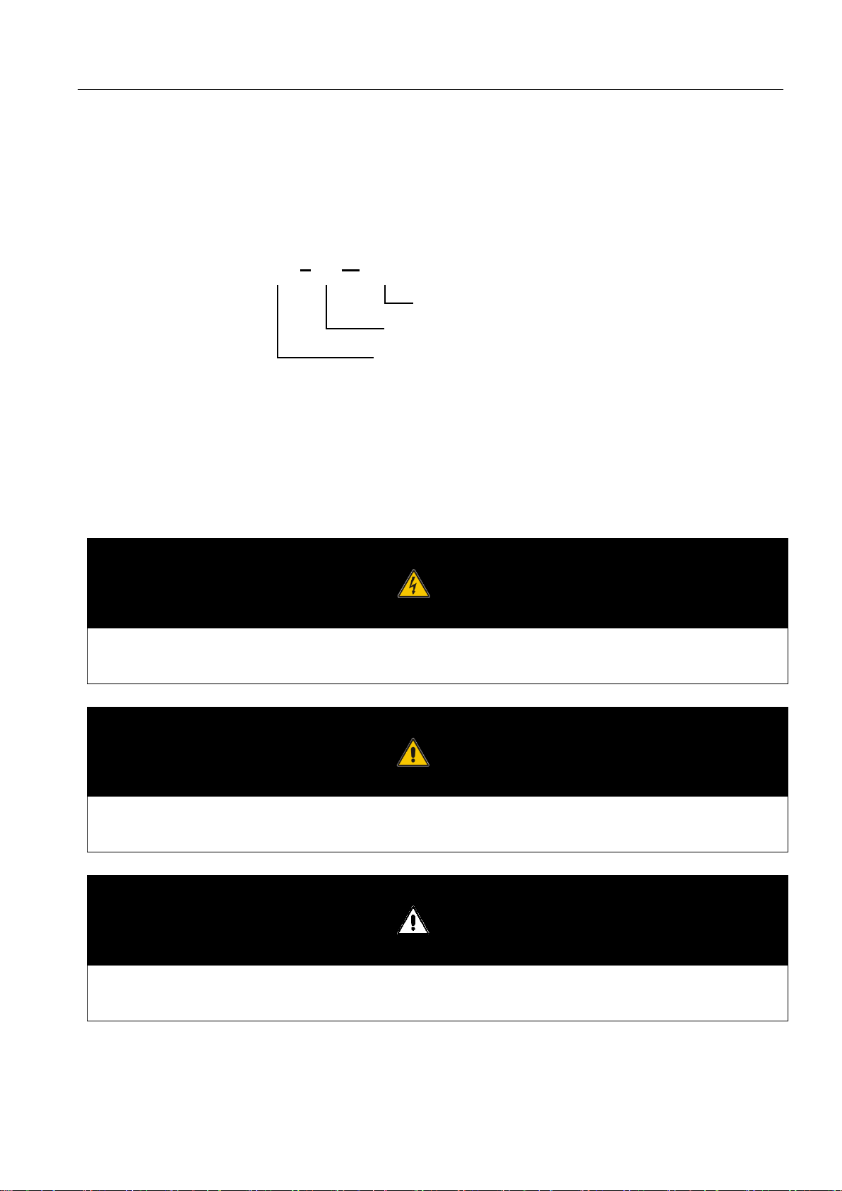
1.1 Model definition
This section introduces product model definition in this user’s manual.
Fig. 1-1 Product model definition
For example:
PWS1-100K-NA: 100kW bi-directional grid-support utility-interactive storage inverter (for North America)
1.2 Symbolic interpretation
Danger
This instruction indicates that there is a safety risk during operation. If this kind of warning information is not followed, it will
directly result in a serious human casualty accident.
Warning
This instruction indicates that there is a potential risk during operation. If this kind of warning information is not follow ed, it
might result in a serious human casualty accident.
Attention
This instruction indicates that there is a potential risk during operation. If this kind of warning information is not follow ed, it
might result in device damage.
50K
NA
PWS1
Bi-directional ES Inverter
Rated Power: 50 to 250K
For North America
2
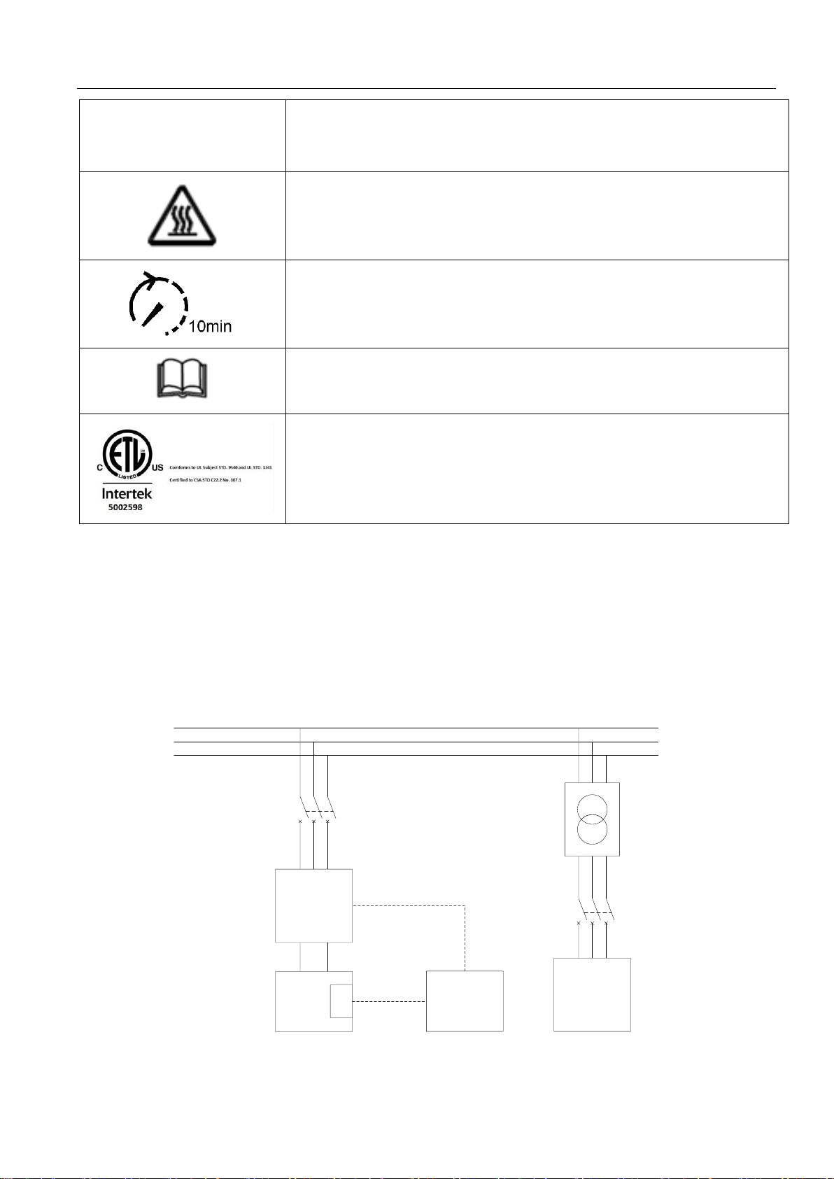
Symbol
Explanation
Risk of burns
Operation after 10 minutes
Read the manual
ETL mark.
The Storage Inverter complies with the requirements of the applicable UL 9540
guidelines.
1.3 System application
energy storage system is composed of battery, storage inverter and AC distribution unit. Batteries are input to the storage
inverter after series-parallel connection of batteries. The storage inverter outputs it to AC distribution unit. It operates in different
modes according to the need.
PWS1-
50/100/150/25
0K-NA
L1
L2
L3
Battery
Array
AC 480V bus
(Optional)
AC MCCB 690V
200A 3P
BMS
RS-485 or
Ethernet
RS-485 or
Ethernet or
CAN
AC MCCB
Industrial/
Commercial
Load
Remote
Controller
(Field-
depend)
480V:208V
+
-
Fig. 1-2 Energy storage system diagram

3
The storage inverter plays a core role in the whole system and is characterized with high conversion efficiency, wide range
input voltage, rapid grid-tie/off-grid switching and convenient maintenance. It has a complete protection function (such as
islanding protection, DC overvoltage protection, AC overvoltage-under-voltage protection, over/under-frequency protection,
inverted sequence protection and output overload protection) and can meet grid-tie/off-grid operation requirements.
Attention
The storage inverter has a built-in isolation transformer.
1.4 Important Safety instructions
This user’s manual is about installation and use of Sinexcel PWS1 series 50~250kW energy storage inverter.
Before installation, please read this user’s manual carefully.
The storage inverter must be commissioned and maintained by the engineers designated by the manufacturer or the
authorized service partner. Otherwise, it might endanger personal safety and result in device fault. Any damage against the
device caused thereby shall not be within the warranty scope.
The storage inverter is only used for commercial/industrial purposes, and it cannot be used as an energy saving device related
to life support device.
This manual contains important instruction for Models PWS1-50K/100K/150K/250K-NA that shall be followed during
installation and maintenance of the Bi-directional Storage Inverter.
Danger
Any contact with copper bar, contactor and terminal inside the device or connected with the loop of utility grid might result
in burning or fatal electric shock.
Don’t touch any terminal and conductor connected with the loop of utility grid.
Pay attention to any instruction and safety documents about power on-grid.
Warning
There might be an electric shock risk inside the device!
Any operation related to this device will be conducted by professionals.
Pay attention to the safety precautions listed in safety instruction and installation documents.
Pay attention to the safety precautions listed in user’s manual and other documents.
4
Warning—large leakage current
Before connecting input power supply, please ensure that the grounding is reliable.
The device must be grounded complying with the local electric codes.
Warning
When storage battery is connected to storage inverter, there is DC voltage at input port. Please pay attention to it during
operation.
Warning
Don’t touch electric parts within 15 minutes after power outage!
There is dangerous energy in capacitance storage. Don’t touch device terminal, contactor and cooper bar and other
electric parts within 15 minutes after disconnecting all device power supplies.
Attention
All maintenance and preservation inside the device require using tools and shall be conducted by trained personnel.
The components behind the protective cover plate which are opened by tools cannot be maintained by users.
Please read this user’s manual before operation.
1.5 Precautions
1.5.1 Personnel requirements
The storage inverter is only commissioned and maintained by the engineers designated by the manufacturer or the authorized
service partner. Otherwise, it might endanger personal safety and result in device fault. Any damage against the device caused

5
thereby shall not be within the warranty scope.
1.5.2 Equipment use scope
The storage inverter is only used for commercial/industrial purposes, and it cannot be used as an energy saving device related
to life support device.
1.5.3 Rack label
Rack label contains important information for safe operation of rack. Don’t tear it up or damage it. S
Ensure that the rack label is clear and readable. If it is damaged or obscure, please replace it immediately.
1.5.4 Description
To facilitate users to use this manual more conveniently, a lot of pictures have been provided in the manual. The pictures can
be only used for explanative and schematic purposes. As for product details, the real product shall prevail.
6
Chapter II Introduction to Modules
2.1 Overall dimension of PCS-AC module
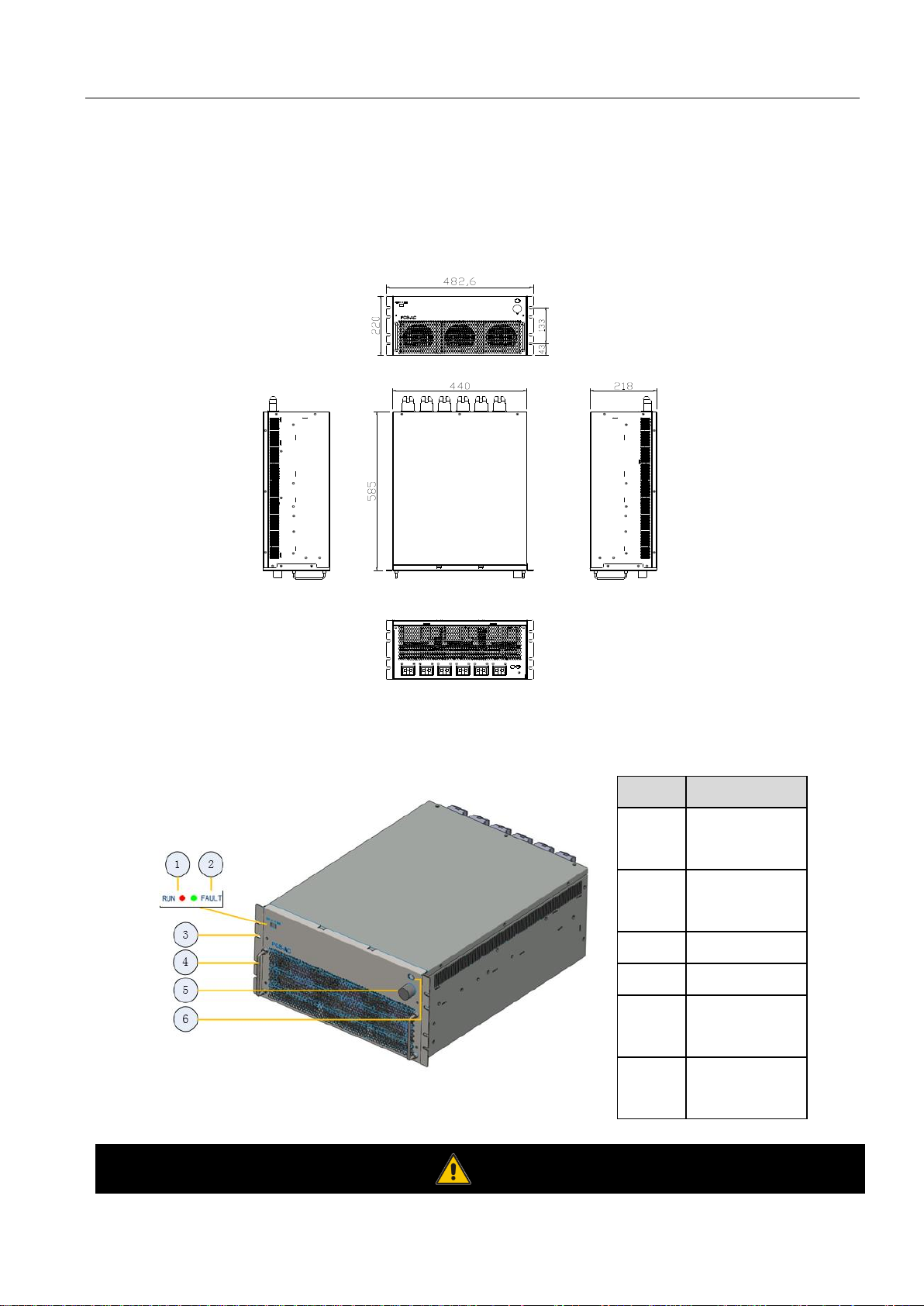
Fig.2-1 is a diagram for overall dimension of PCS-AC module case and installation hole.
Fig. 2-1 Overall dimension and installation diagram for PCS-AC module
Fig. 2-2 Front view for PCS-AC module
Position
Description
1
Normal indicator
light
2
Fault indicator
light
3
Hanger
4
Handle
5
Communication
cable
6
Power supply
cable
Warning

7
The handle on the front panel of the module cannot bear the weight.
The front panel of PCS-AC module has two LED lights, namely one green (Normal) light and one red (Alarm) light. When the
device is in standby state, the green light (Normal) flickers once every 1s. When the device is in sleep state, green and red
lights are off. When the device is in normal operation, the green light (Normal) is always on. When the device has a fault
warning, the red light (Alarm) will be always on or flicker.
8
Chapter III Introduction to System
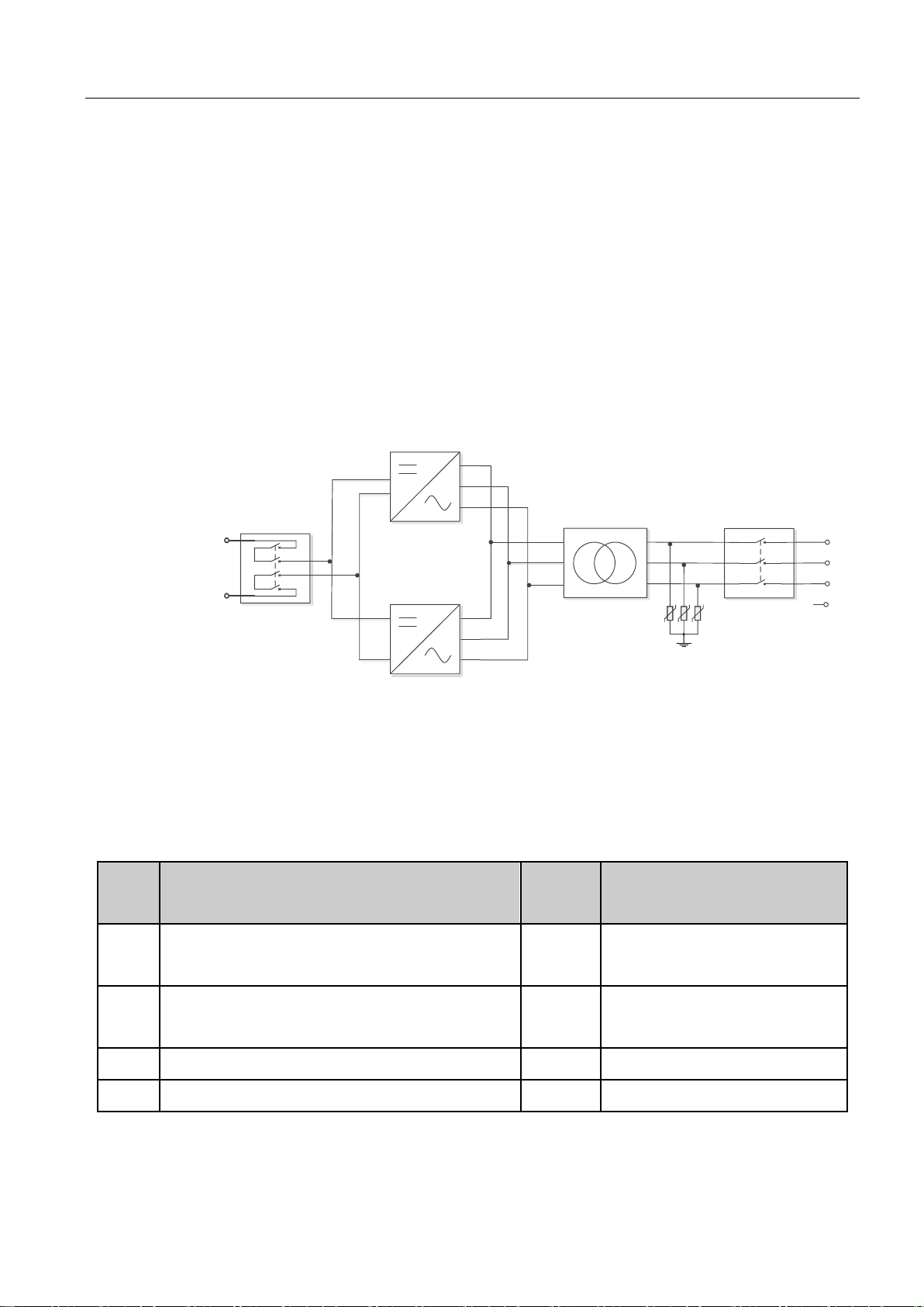
3.1 System composition
PWS1-50K/100/150K/250K storage inverter is composed of 1 or multiple set(s) of PCS-AC modules. The modules identify
master-slave systems through the dial-up codes on the panel. #1 is a master system, while other modules track the master
system. The storage inverter rack is equipped with lightning protector, AC/DC breaker and distribution units. If grid-tie/off-grid
switching is to be achieved, extra power distribution unit needs to be added. Fig.3 -1 is a topological graph for its composition
and structure.
L
1
L
2
L
3
N
Transformer AC Breaker Q3
+
IN1
-
PCS AC 1
PCS AC n (n=0/ 1/ 2)
DC Breaker Q1
AC SPD
Fig. 3-1 Topological graph for storage inverter
Main composition of PWS1-50K/100/150K/250K storage inverter rack is shown in Table.3-1.
Table 3-1 Main composition of the storage inverter rack
Serial
No.
Item
Quantity
Remark
1
Rack
1
The rack is equipped with distribution
components.
2
PCS-AC module
1~5
50kW 1 set; 100kW 2 sets; 150kW 3 sets;
250kW 5 sets
4
Isolation transformer
1 5
Power Management Unit
1
Built-in on the rack door.
3.2 Technical parameters
Table 3-2 is detailed parameters for storage inverter.

9
Table 3-2 Technical parameters
PWS1-50K-NA
PWS1-100K-NA
PWS1-150K-NA
PWS1-250K-NA
AC parameters
Rated output
power
50kW
100kW
150kW
250kW
Wiring mode
3-phase and 4-wire system (including transformer)
Output overload
capacity
55kW
110kW
165kW
275kW
On/off-grid switch
time
≤ 80ms (For shorter time, it can be customized.)
Utility-Interactive
AC voltage
Rated voltage: 480V; voltage range: 423V~528V
Voltage accuracy
<1%
Ramp rate
accuracy
<10%
Frequency
60Hz, frequency range: 59.5Hz~60.5Hz
Frequency
accuracy
<0.1Hz
AC rated current
60A
120A
180A
300A
Maximum AC
input short circuit
current
(charge mode)
1200A
2500A
3500A
6000A
Maximum output
overcurrent
protection
Yes
Yes
Yes
Yes
AC output fault
current and
duration
300A 200ms
600A 200ms
900A300ms
1500A 300ms
Trip limit and trip
time accuracy
80ms (±30ms)
80ms (±30ms)
80ms (±30ms)
80ms (±30ms)
Total harmonic
distortion of
current
<3%
Power factor
0.8 leading~0.8 lagging adjustable
PF accuracy
±2%
10
Active power
accuracy
5%
Inactive power
accuracy
8%
Stand-alone
Rated output
voltage
480Vac
Rated output
frequency (Hz)
60Hz
DC parameter
DC voltage range
650V (500V-850V)
DC input/output
current
100A
200A
300A
500A
Rated DC power
50kW
100kW
150kW
250kW
Charging mode of
on-grid
It can charge and discharge with constant current and power and supports three-section
charging (pre-chargeequalized chargefloating charge).
System
Dimension
800mm*2160mm*800mm (W*H*D)
1200mm*2160mm*800mm
(W*H*D)
Weight
465kg
680kg
910kg
1280kg
Noise
≤70dB
Enclosure
NEMA1(IP20)
Allowable
environment
temperature
-20℃~50℃(auto de-rate at 45℃ or above)
Cooling mode
Forced air cooling
Humidity
0~95% (no condensation)
Allowable
maximum
elevation
3000m
Display
Touch screen
Standard
communication
interface
RS 485, CAN and Ethernet
11
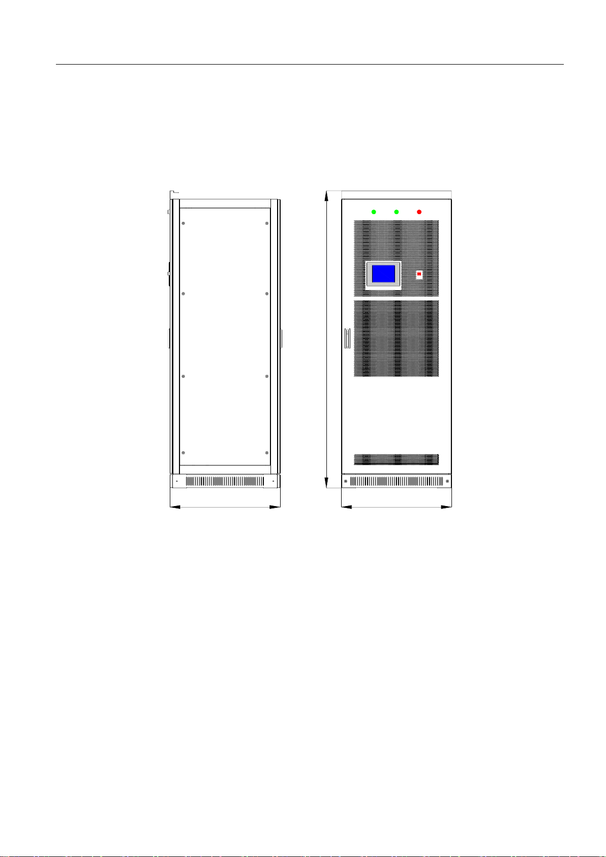
3.3 Overall dimension
The overall dimension of the storage inverter is shown in Fig.3-2.
The PWS1-50K/100K/150K Rack, width: 800mm, height: 2,160mm (without lifting rings); depth: 800mm.
The PWS1-250K Rack, width: 1200mm, height: 2,160mm (without lifting rings); depth: 800mm.
故障/FAULT
电源/POWER 运行/RUN
EPO
2160
800800

12
Fig. 3-2 Overall dimensions of storage inverter
3.4 Appearance description
The appearance of the storage inverter is shown in Fig.3-3. Screen body is mainly composed of touch screen, normal indicator
light, alarm indicator light and emergency shutdown button etc.
故障/FAULT
电源/POWER
运行/RUN
EPO
4
1
2
3
5
Fig. 3-3 Front look of PWS1 50~250K-NA storage inverter
Position
Description
1
Power indicator light
2
Fault indicator light
3
Normal indicator light
4
Emergency
shutdown button
5
Touch screen
Taking PWS1-150K-NA as an example: After opening the front door, the internal layout is shown in Fig.3-4. Main components
include module, AC/DC breaker and surge protection device.
The internal layout of PWS1-250K-NA is shown in Fig.3-5.
2100
1200800
故障/FAULT电源/POWER 运行/RUN
EPO

13
Fig. 3-4 Internal layout diagram for PWS1-50~150K-NA
storage inverter
Position
Description
1
PCS-AC module
(1~3 module(s))
2
Battery switch
3
AC breaker (load)
1
2
4

14
1
2
3
Fig. 3-5 Internal layout diagram for PWS1-250K-NA
storage inverter
Position
Description
1
PCS-AC module
(1~5 module(s))
2
Battery switch
3
AC breaker (load)

15
Chapter IV Device Installation
4.1 Transport and storage
Rack and module of the storage inverter are packed separately in the packing cases. That is, multiple modules and a rack
packed separately in the packing cases. During device transport and storage, pay attention to the logo on the packing case.
The storage inverter is modularly designed so as to facilitate device positioning and transport. The selection of storing position
should ensure that:
There is no corrosive gas around it.
There are over-wetting and high-temperature sources.
It is not a dusty environment.
It complies with the firefighting requirements.
Attention
During rack transport and storage, stacking is not allowed. The device top cannot be placed with other articles.
The rack should be placed vertically at forward direction. Don’t keep it upright place it horizontally.
4.2 Removal
When removing the module of the storage inverter which is not unpacked from packing case, a forklift can be used to remove
the whole case.
Users can lift the device bottom with a forklift or through the lifting hole on its top with a crane.
Fig. 4-1 Moving storage inverter
Warning

16
Before the rack is moved, please ensure that the module is fixed stably.
4.3 Open-case inspection
4.3.1 Overview
Before installation of storage inverter, open-case inspection needs to be conducted. The inspection includes the following:
Check whether the items in the packing are consistent with real items.
Check whether the data of product nameplate is consistent with the contract, including product model, rated capacity
and voltage grade.
Check whether the ex-factory documents and accessories are complete.
Check whether the module of the storage inverter is deformed.
Check whether the inverter rack is deformed, paint peeling or loose.
4.3.2 Packing list
Refer Table 4-1 for packing list of rack of storage inverter:
Table 4-1 Packing list
Item
Quantity
Remark
User’s manual
1 copy
Overall dimension and foundation
installation diagram
1 copy
Schematic diagram
1 copy
External terminal diagram
1 copy
Certificate of quality
1 copy
4.4 Installation requirements
4.4.1 Environment requirements
It is installed indoor. Direct sunshine, rain and ponding should be avoided.
The installation environment is clean. The air should not contain lots of dust.
The installation position should not be shaky.
Environment temperature should be -20~55℃. (The software conducts de-rating for 45℃ above.)
The installation position is convenient for observing touch screen.
4.4.2 Ground requirements
The rack of the storage inverter needs to be installed on the flat ground. The weight-bearing of the ground for installation
should be greater than 1,000kg/ m
2
.

17
4.4.3 Ventilation
The storage inverter is forced air-cooling. Every module has an independent ventilation route. The module heat dissipation
mode is air inlet in the front and air outlet in the rear. The cold air is inhaled from the mesh openings of front door of the rack.
After heat absorption, the hot air is discharged from the mesh openings of rear door of the rack.
To ensure the quality of air inlet, please carry out installation according to the operation space requirement in 4.4.4, and a
proper space should be reserved for air inlet and outlet. A blower is required to be installed in the machine room so as to
ensure that the heat emitted from the storage inverter can be discharged outside the room.
Attention
At the rear of the rack, heat dissipation and ventilation equipment needs to be installed so as to ensure that the heat emitted
from the storage inverter can be discharged outside the machine room.
4.4.4 Operation space
The installation space of the storage inverter should have a proper distance from its peripheral walls so as to ensure that the
machine door can be opened and closed conveniently and there will be sufficient space for module insertion and extraction,
normal heat dissipation and user’s operation.
B
A
Fig. 4-2 Installation space of storage inverter
Position
Description
A front
≥1,000mm, ensure that the
front door of the rack can be
fully opened. There is
sufficient space for cold air
to enter. Users can
conveniently insert and
extract the module and
operate the breaker.
B rear
≥1,000mm, ensure that the
rear door of the rack can be
fully opened. Ventilation and
heat dissipation should be
ensured. Users can have
sufficient space for
maintenance.

18
4.4.5 Other requirements
1) Waterproofing
The protection grade of the rack of the storage inverter is IP20. It is only installed and used in a dry and clean room. Water
leakage in room should be avoided so as to prevent the storage inverter from being damaged.
2) Rat-proofing
After wiring, fireproofing mud should be used to seal inlet and outlet holes so as to meet the rat-proofing requirement.
Fireproofing mud is not provided by Sinexcel.
4.5 Rack installation
After the rack is removed to the installation position of energy storing deice with a forklift or a tool. Fine adjust the rack and
remove it to the designed position, open the internal door of rack, use M13 screw to fix the rack.
Fig. 4-3. Diagram for rack base (Upper: 50k~150k; Below: 250k)
57,3
22,8
640
685,5
38,3
22,8
544
579,5
22,8 22,8
579,5
22,8
12-24
12-14
Front of rack
Front of rack

19
When the rack needs to be fixed on the steel channel, Φ14 holes can be made in the steel channel. Fix the rack to the steel
channel with screws.
Fig. 4-4 Fix the rack to the steel channel
Fig. 4-5 Fix the rack to the concrete floor
When the rack is fixed to the concrete floor, make holes on the floor and fix the rack to the concrete floor with expansion
screws.
4.6 Electrical connection
4.6.1 Input requirement
DC voltage of the storage inverter should be within the input scope, or the storage inverter will be unable to operate. When
configuring serial quantity of batteries, the maximum charging voltage and minimum discharging voltage should be fully
considered. For details, please consult our technical personnel.
The battery pack working with the PCS should be certified by CSA E61233 or UL1973. And the charging/discharging voltage
should be between 520Vdc and 850Vdc. It should also be equipped with DC air switch and the BMS certified by CSA No. 0.8
or UL991+UL1998. While installation of external battery pack, please make sure switches in fig4-6/fig4-7 in 4.6.3 are
disconnected.
Attention
Every DC input circuit branch in Bi-directional Hybrid Storage Inverter should be able to operate independently. It does not
support common battery pack. The batteries need to be connected to each branch port.
Cable
groove
Fixed screw
Channel
steel
cable
groove
Ground
Foot screw

20
4.6.2 Output reqirement
The output of the storage inverter is 3-phase and 4-wire. When designing energy storage system, the storage inverter has
been equipped with an isolation transformer, the voltage of its output side can directly be connected to the low-voltage utility
grid.
4.6.3 Wiring mode
The storage inverter adopts the wiring mode of lower inlet and outlet. The cables fall into the cable trough via the wire holes
at the base. Open the front door and dismantle the internal door to display wiring the cooper bars. As for wiring requirements,
single cables or multiple cables with proper wire diameter should be selected (image update). It is suggested that the current
in 1mm
2
wire should be ≤3A.
The installation instructions shall indicate that the wiring methods in accordance with the National Electrical Code, ANSI/NFPA
70 are to be used.
1
2
3
4
6
5
7
Position
Description
1
DC+
2
DC-
3
PE
4
A/L1
5
B/L2
6
C/L3
7
N
Fig. 4-9 PWS1-50K-NA rack wiring copper bars
1
2
3
4
6
5
7
Position
Description
1
DC+
2
DC-
3
PE 4 A/L1
5
B/L2
6
C/L3
7
N
Fig. 4-10 PWS1-100K-NA rack wiring copper bars

21
1
2
3
4
6
5
7
Position
Description
1
DC+
2
DC-
3
PE 4 A/L1
5
B/L2
6
C/L3
7
N
Fig. 4-11 PWS1-150K-NA rack wiring copper bars
1
2
3
4
5
6
7
Position
Description
1
DC+
2
DC- 3 PE
4
A/L1
5
B/L2
6
C/L3
7
N
Fig. 4-12 PWS1-250K-NA rack wiring copper bars
4.6.4 System grounding
The modules in the storage inverter realize grounding connection with the rack through hangers.
As for rack grounding, the rack bottom is installed with grounded cooper bars. During wiring, refer to the following table for
cable diameter. The grounding resistance should be less than 4Ω.

22
Notice that the ac output neutral is not bonded to ground.
Warning
Rack and modules need to be grounded reliably!
4.6.5 DC port wiring
1) Use a multi-meter to measure the voltage of storage battery port, and ensure that the voltage is within input voltage range
of storage inverter.
2) Disconnect DC switch at previous level. Wiring operation can be conducted after using a multi-meter to measure and confirm
that there is no voltage between positive and negative poles of DC input.
3) Connect the positive pole of storage battery to “DC+” of DC input of Q1 switch.
4) Connect the negative pole of storage battery to “DC-” of DC input of Q1 switch.
5) Confirm wiring firmness.
Danger
Disconnect DC distribution switch and ensure that there is no dangerous voltage in the system during wiring.
Attention
The positive and negative poles of batteries cannot be connected inversely. Before wiring, a multi-meter needs to be used
for measurement.
4.6.6 AC port wiring
1) Use a phase-sequence meter for measurement, and ensure that the phase consequence of wires should be a positive
Rated power
Copper PE line section recommendation
(mm²)
50kW
≥16
100kW
≥25
150kW
≥35
250kW
≥45

23
consequence.
2) Disconnect AC output distribution switch Q2 at back level in storage inverter.
3) Use a multi-meter to measure and ensure that the cables connected to the terminals are electrically neutral.
4) During on-grid, A(L1)/B(L2)/C(L3) phases of AC output distribution switch Q2 of utility grid and PE are respectively
connected to A(L1)/B(L2)/C(L3) phases of utility grid and PE.
If grid-tie/off-grid switching is to be achieved, extra power distribution unit and wires need to be added.
5) Confirm wiring firmness.
Warning
Ensure that there is no dangerous voltage at connection points during wiring.
Attention
All wires are connected to the wiring terminals externally from the wiring holes at the bottom of storage inverter. After wiring,
fireproofing mud should be used to seal the wiring holes.
4.6.7 Wiring of terminal strips
Except power cable connection in the whole storage inverter, there are also auxiliary power connection, input and output of
some node signals. All of them are led to the terminal strips with cluster cables in the rack. The port definition of external wiring
for terminal strips is shown in Fig.4-13.
BMS Fault Signal
On/Off grid Switch Node 1
On/Off grid Switch Node 2
From external BMS
To external RS485
From external AUX Power
Fig. 4-6 Definition of terminal strip ports

24
4.7 Check after installation
After installation of storage inverter, inspection is conducted after the installation:
1) The device should be placed and installed reasonably, meeting safe distance requirements.
2) Wiring should be correct at one time. Lower leading wire and ground screen are in good connection. The constructor is
required to inspect the grounding resistance.
3) Compare ex-factory main wiring diagram and site wiring. Check whether there is any difference and judge whether such
difference will affect the safe operation of energy storage system.

25
Chapter V Commissioning and Operation
5.1 Status
After external wiring of the storage inverter is completed, and wiring is fully checked, close the breaker in AC port. The storage
inverter can be switched in different modes under the conditions in Fig.5-1.
Ongrid
Alarm
Power
-off
Offgrid
Stand
-by
Power
-on
Sending power-on
command
V
EOD<Vbat<Vchg
V
bat
<
V
EOD
Failure
Failure cleanup
Sending power-on command
Setting on-grid
charging/discharging
Sending power-off
command
Sending power
-
off
command
Sending power
-
off
command
Failure
Failure cleanup
Off
-
grid to on-grid
On
-
grid to on
-
grid
Fig. 5-1 Status diagram for storage inverter
Refer to the following table for status of storage inverter.
Table 5-1 Status of storage inverter
Status
Conditions
State indication
Standby
DC switch is closed, AC switch is closed, and the
device has no fault.
RUN green light flickers quickly, and the
module green light flickers quickly.
On-grid
The device does not alarm, on-grid mode is set, and
the device receives startup command.
RUN green light is always on, and the module
green light is always on.
Off-grid
The device does not alarm, off-grid mode is set, and
the device receives startup command.
RUN green light is always on, and the module
green light is always on.
Alarm
Any fault information
Red light is always on, the module red light is
always on or flickers, and the buzzer makes an
alarm.
Shutdown
The device receives shutdown command.
RUN green light flickers slowly, and the
module green light flickers slowly.

26
5.1.1 Automatic startup
In automatic startup, the storage inverter system will automatically inspect and judge startup conditions. If the system function
is normal and it meets the system setting conditions, it will start automatically. If the voltage of utility grid is too low or high, the
frequency is abnormal, DC voltage is too low or high, the storage inverter will make an alarm, shut down automatically and
stop providing power outside.
After meeting the following conditions, the storage inverter will restart automatically, and the output is recovered.
DC voltage is normal.
The voltage of utility grid is normal in on-grid mode, or there is no voltage of utility grid in off-grid mode.
Operation mode setting is correct.
There is no other alarm fault.
If automatic startup is not set in storage inverter, users can start the device by hands through touch panel.
5.2 Startup and shutdown
The storage inverter must be installed completely and commissioned by engineers. External power switches have been closed,
and then startup steps can be conducted.
5.2.1 Check before startup
Before startup, check the device according to the following steps:
1) Inspect and ensure that no damage sign is in external part of the module, and DC breaker Q1 and AC breaker Q2 are at
“OFF” position.
2) Complete installation according to Chapter IV, and check whether DC input wiring and AC output wiring in the storage
inverter are normal, and the grounding is good.
3) Check whether battery voltage is normal.
4) Check whether phase voltage and wire voltage in utility grid side are in the normal range, and record the voltage.
5.2.2 Startup steps
These startup steps are applicable to the circumstance that the storage inverter system is in outage state and can be started.
Operation steps are as follows:
1) Close output switch of battery rack and connect power supply to DC port of the device.
2) Close DC breaker Q1. Green indicator light flickers in green. After about 10s, the red indicator light is always on in red. At
this moment, THE HMI will indicate the warning information such as “under-voltage of grid” and “abnormal grid frequency”. If
step 2 and step 3 are conducted before the red light is always on, the flickering in red will not appear.
3) Set monitoring parameter to control operation mode. See setting information in 6.2.
4) After step 3 is conducted, return to “main wiring diagram” on THE HMI and start DC/AC modules.
5) According to the current operation mode setting and DC input, the host will automatically operate and display.

27
5.2.3 Shutdown steps
During normal operation of storage inverter, the following steps can be conducted if shutdown is required.
1) On THE HMI, return to “main wiring diagram”, and click AC/DC module to “shut down”.
2) Normally, main monitoring indicator light flickers in green for about 30s.
3) Disconnect DC breaker Q1.
4) Disconnect AC breaker Q2.
As for above operation process, it has been shut down after step 2 is conducted. The power components stop operating in
system, and BUS bar and auxiliary power supply in system still exist for a long time. Therefore, relevant control system is still
in standby state. In this state, device setting and maintenance are not allowed. After step 4 is conducted, the storage inverter
is in a shutdown state, and the internal connector bars are electrically neutral in system. After the internal capacitance in
modules fully discharges, relevant maintenance and setting can be conducted.
5.2.4 Emergency shutdown
When the storage inverter system is abnormal, press the emergency shutdown button “EPO” on the rack door and then conduct
steps 3~5 in 5.2.3.
Warning
To prevent personal injury, please use a multi-meter to measure the voltage at input terminal if case maintenance or
opening is conducted. After ensuring that there is no mains supply, relevant operation can be conducted!
After about 15 minutes, the upper cover plate can be opened after DC BUS bar capacitance fully discharges (refer to
warning label on module case surface).

28
Chapter VI Operation Control Display Panel
6.1 Operation instructions
Operation control can be conducted via HMI (human-computer interface). This section introduces the HMI display content and
settable parameters.
6.1.1 Main monitoring startup
After auxiliary power of the storage inverter is connected, THE HMI is on. At this moment, an initializing interface will appear.
It shows that the system is booting. After system booting, the interface will disappear.
The system is booting,please wait……
Fig. 6-1 Initializing
6.2 Home
After initializing, the home page is shown. On the main wiring diagram, system AC/DC voltage and current, general system
status can be seen.
Fig. 6-2 main wiring diagram

29
6.3 Information
Fig. 6-3 System information
In the Info pages, administrators can obtain the overview of the entire system operation parameters.
6.4 Logs
Fig. 6-4 Logs
In logs page, users can review current alarm, past alarm, operation record, status record of the system, and operation curves.

30
6.5 Settings
6.5.1 Local
Fig. 6-5 Local settings
In this page, system time, communication baud rate and IP address, etc. can be set.
6.5.2 Model
This page is reserved for other models.
6.5.3 System
Fig. 6-6 System parameter interface
Boot mode: default set “manual”.
Energy Management mode: please set it as “AC”. If “DC” is set according to the actual demand, set “charging and discharging
current” and “charging and discharging power” in DC parameter
DC setting mode: reserved function for special models.
Word1/2: reserved function for diagnosis.

31
6.5.4 AC settings

32
Fig. 6-7 AC settings

33
AC operation mode: to set the operation mode, constant power or constant inactive power.
PF: set to regulate the PF of the entire storage system
Power configuration: Set to regulate the power of the storage system
Q configuration: Set to regulate the inactive power of the storage system
Grid reconnection delay: please keep the default configuration.
Normal ramp rate: please keep the default configuration. This function will apply when set power changes. The default value
is 2 rated power per second, which means within 0.5 seconds the system can runs to full output.
Soft-Start/Reconnection ramp rate: please keep the default configuration. This function will apply when system suspend
happens caused by utility voltage abnormal, and reconnect after utility restore normal. The default value is 2, twice of rated
power per second, which means within 0.5 seconds the system restores to full output.
Off-grid V range: to regulate the off-grid output voltage.
P Change mode: to set the power change pattern, step-to-top, or ramp-rise.
Ground-fault detection: enable or disable ground-fault detection.
Anti-Islanding: enable or disable anti-islanding function. For more information, please refer to UL1741 Supplement A or other
similar rules about Utility-Interactive Distribute Generators .
Off grid start mode: Can be set as step-to-top, or ramp-rise.
Active power regulation: enable or disable active power regulation.
6.5.4.1 FVRT
FVRT: frequency/voltage ride-through, this function can be enabled or disabled, for more information, please refer to UL1741
Supplement A or other similar rules about Utility-Interactive Distribute Generators .
O/UVR* protect voltage: to set the over/under voltage ride though protect voltages.
O/UVR* trip time: to set the over/under voltage ride though trip times.
O/UFR* protect frequency: to set the over/under frequency ride though protect frequencies.
O/UFR* trip time: to set the over/under frequency ride though trip times.
6.5.4.2 Volt/Var
Volt/Var regulation is only available when enabled. In Volt/Var mode, the Q configuration is disabled.
Volt/Var point: to set the Volt/Var switch point.
When the actual voltage between Volt/Var point 1 and 2, the capacitive inactive power will be increased.
When the actual voltage between Volt/Var point 3 and 4, the inductive inactive power will be increased.
For more information, please refer to UL1741 Supplement A or other similar rules about Utility-Interactive Distribute
Generators .
Max inductive reactive regulation: to set the maximum inductive reactive power regulation.
Max capacitive reactive regulation: to set the maximum capacitive reactive power regulation.
6.5.4.3 Volt/Watt
Volt/Watt regulation is only available when activated and operating in discharge mode. When the actual voltage is above the
point, the active power will be regulated with the ramp rate. The ramp rate is defined as multiple of set active power per 1% of
rated voltage that above the Volt/Watt point.

34
Volt/Watt point: to set the Volt/Watt trigger threshold.
Volt/Watt ramp rate: to set the ramp rate when Volt/Watt is triggered.
Volt/Watt delay: to set the output power restore time delay after the utility voltage restores normal.
6.5.4.4 Freq/Watt
Available when activated and operating in discharge mode. When the actual frequency is above the point, the active power
will be regulated with the ramp rate. The ramp rate is defined as multiple of set active power per hertz that above the above
the Freq/Watt point.
Freq/Watt point: to set the Freq/Watt trigger threshold.
Freq/Watt ramp rate: to set the ramp rate when Freq/Watt is triggered
6.5.5 DC settings
Fig. 6-8 DC settings
DC operation mode: please set it as “auto”.
CHG/ DCRG current: Set charging or discharging current within the rated power according to the actual demand. (Available
only after “energy dispatching mode” in “system parameter” is set as “DC dispatching”, and DC operation mode is set as
“constant I mode”.)
CHRG/ DCHRG power: Set charging and discharging power within the rated power page according to the actual demand. (It
is valid only after “energy dispatching mode” in “system parameter” is set as “DC dispatching”, and DC operation mode is set
as “constant P mode”.)
EOD V of Batt: Prioritize the setting according to the manufacturer’s recommendation. Conduct setting according to the
following data in case of manufacturer’s data cannot be obtained:
Set 2V lead battery according to 1.67~1.80V* number of batteries in series;
set 3.2V lithium batteries according to 2.70~2.75V* number of batteries in series.
Float CHRG V: Prioritize the setting according to the manufacturer’s recommendation. Conduct setting according to the
following data when manufacturer’s data cannot be obtained: Set 2V lead batteries according to 2.20~2.27V* number of
batteries in series; set 3.2V lithium batteries according to 3.60~3.70V* number of batteries in series. Keep consistent with the
equalizing voltage of battery.

35
Equal CHRG V: Prioritize the setting according to the manufacturer’s recommendation. Conduct setting according to the
following data when manufacturer’s data cannot be obtained: Set 2V lead battery according to 2.20~2.27V* number of batteries
in series; set 3.2V lithium batteries according to 3.60~3.70V* number of batteries in series.
E/C to F/C I: Prioritize the setting according to the manufacturer’s recommendation. Set 2V lead batteries according to
0.02C~0.05C in case of manufacturer’s data cannot be obtained. Other connection types can be set as 1A.
Max. CHRG I: Set 50K as 100A, set 100K as 200A and set 150K as 300A.
Max. DCHRG I: Set 50K as 100A, set 100K as 200A and set 150K as 300A.
Max. Precharge I: Set 50K as 100A, set 100K as 200A and set 150K as 300A.
DCHRG Inception Voltage: Conduct setting according to EOD voltage when there are no special requirements.
DCHRG End Voltage: Conduct setting according to EOD voltage when there are no special requirements.
Precharge V: Conduct setting according to EOD voltage when there are no special requirements.
Precharge to Quick Charge Voltage: Conduct setting according to EOD voltage when there are no special requirements.
Precharge Time: Conduct setting according to client’s requirement. When the client does not require pre-charge function, set
it as 1min.
Precharge Max. I: Conduct setting according to client’s requirement. When the client does not require pre-charge function,
set it as 10A.
Charge Cutoff Current: keep the default value.
6.5.6 AC Debug
Fig. 6-9 Parameter diagnosis interface
Reserved function for diagnosis.
6.6 On/Off
Enter “On/Off” interface to conduct manual startup and shutdown operation in this interface.

36
Fig. 6-10 On/Off
After parameters are set and startup condition is met, machine startup and shutdown can be operated via “Sys ON” and “Sys
OFF”.

37
6.7 Control mode
Enter “ctrl mode”. It includes “Local manual”, “Local auto”, “Remote control” and “Lock out” functions.
Fig. 6-11 Control mode
Local manual: Set parameters on the monitoring screen to control machine operation.
Local auto: It is used with “local auto”. Under this mode, monitor and maintain the current parameter setting (unchangeable),
and operate according to the period for “local auto”—power configuration.
Remote control: Under this mode, monitor and maintain the current parameter setting. The parameter setting can be changed
by remote control.
Lock out: Under this mode, monitor and maintain the current parameter setting. The parameter setting cannot be changed by
remote control.
In case of no special requirements, please set it as “local manual” mode.
6.8 Tactics
Fig. 6-12 Local strategy
The tactics page are reserved functions for specific users who need self-controls

38
6.9 Log in/out
Fig. 6-13 Login page
Click “login/out” to enter login page, enter login password 123456789 and obtain administrator authority.

39
Chapter VII Communication Mode
7.1 Communication interface
The storage inverter supports Modbus protocol, adopts RS485 and Ethernet communication interface and facilitates users to
conduct background monitoring for the storage inverter and realize remote signaling, remote metering and remote regulating
of storage inverter.
7.1.1 RS-485 port
The front door of the storage inverter is embedded with touch screen Management Unit. User interface can be seen at its back.
In particular , the position number of RS485 communication interface in the monitoring panel is J23. It is led to terminal strip
ports 9 and 10. Users can transfer serial port signal to the one which can be processed by PC via interface converter (such
as RS485 transferred to 232). The storage inverter is commissioned alone via background software. It can read operation and
warning information. Corresponding setting, startup and shutdown operations can be conducted.
Power
Management
Unit
LAN
USB
CAN L
CAN H
CAN GND
485_3B
485_3GND
485_3A
SD
J25
J23
To
external
RS485
RS485/232
Converter
Fig. 7-1PC conducts monitoring via RS485

40
7.1.2 Ethernet port
The monitoring panel integrates Ethernet port with position numbered as RJ25. It supports Modbus TCP/IP protocol and has
its own IP address like a PC. Ethernet connection requires a switch, and fixed IP needs to be set. Connecting cables are
twisted pair (namely network cable). The internet ports of multiple The storage inverter are connected to the switch, and the
switch is connected to remote control computer. The state of the storage inverter can be monitored and controlled in real time
by setting IP address and port number in the monitoring computer.
Fig. 7-2 Ethernet communication scheme for single storage inverter
Fig. 7-3 Ethernet communication scheme for multiple storage inverters
7.1.3 Communication with BMS
The inverter communicates with battery management unit (BMS) to monitor battery state information, give an alarm and
provide fault protection for battery according to the battery state and improve the safety of storage battery. It supports CAN
communication. In particular, the position number of CAN communication interface in the monitoring panel is J23. It is led to
terminal strip ports 7 and 8.

41
Power
Management
Unit
LAN
USB
CAN L
CAN H
CAN GND
485_3B
485_3GND
485_3A
SD
J25
J23
From
external
BMS
CAN
BMS
Fig. 7-4 Energy storage inverter and BMS communication
7.2 Monitoring system structure
Background monitoring system can operate and control the storage inverter via computer network. This has provided great
convenience for learning about the operation of energy storing station. The overall structure diagram for monitoring system is
shown in Fig.7-5.
IE access
LAN
RS485
LAN
RS485
Fig. 7-5 Structure diagram for background monitoring system

42

Chapter VIII Maintenance and Preservation 43
Chapter VIII Maintenane and Preservation
8.1 Operation environment requirements
Device operation environment must comply with the operation environment required for the device:
Allowable environment temperature: -20~55℃ (power de-rating for 45 ℃above)
Allowable relative humidity: 0~95% (non-condensing)
Allowable maximum elevation: 3,000m
Note: When exceeding the maximum elevation, the storage inverter will have de-rating output. Please consult customer service
center for specific de-rating coefficient.
8.2 Electrical and fixed connection inspection
After being put into operation, conduct regular inspection on device’s electrical and fixed part connection. Such inspection is
advisably conducted every three months. Record for each inspection should be made.
Rack grounding connection;
Module grounding connection;
Electrical connection for DC input;
Electrical connection for AC input;
Electrical connection for auxiliary power supply;
Electrical connection for communication cables.
AC/DC switch, SPD and fan.
Access monitored fault information.
8.3 Clearing and cleaning
Before the device is put into operation, the dust and sundries in its cooper bars, terminals and mesh openings should be
cleaned.
After the device is put into operation, the dust in machine room should be cleaned regularly. Check whether the ventilating
and air exhaust facilities in machine room are normal. They are advisably cleaned once every three months.

Appendixes
Appendix 1: Fault information of storage inverter
Table 9-1 presents the visible fault types of storage inverter. From this table, users can simply and quickly identify the system faults
from the fault types displayed on touch screen. In multiple module parallel system, the warning information interface will indicate
the number of fault slaves and fault type.
Table 9-1 Fault information
Fault type
Description
Overvoltage of utility grid
The voltage of utility grid is higher than the set upper limit. After faults are recovered,
restart the storage inverter.
Overvoltage of utility grid
The voltage of utility grid is lower than the set lower limit. After faults are recovered,
restart the storage inverter.
Inverted sequence of utility grid
The phase sequence of AC utility grid is inverse.
Abnormality of utility grid frequency
Utility grid frequency exceeds the set scope. After faults are recovered, restart the
storage inverter.
Islanding of storage inverter
There is islanding in storage inverter.
Overvoltage of DC input
Overvoltage of DC input is higher than the upper limit. After faults are recovered,
restart the storage inverter.
Low DC voltage
Overvoltage of DC input is lower than the lower limit. After faults are recovered, restart
the storage inverter.
Abnormality of BUS bar voltage
DC BUS bar voltage is too high or low, which results in system shutdown. After faults
are recovered, restart the storage inverter.
Abnormality of balanced circuit
BUS bar voltage is imbalanced (internal fault information)
Soft start fault
Soft start fault (internal fault information)
Emergency shutdown
EPO action, emergency shutdown
Over-temperature of inverter
The temperature of inverter radiator is too high.
Fan fault
At least one cooling fan has faults.
Monitoring parameter setting fault
Monitoring parameter setting is incorrect. Please modify the setting.

Appendix 2: Quality assurance and after-sales service
1) Quality assurance
If there are fault products during warranty period (refer to the warranty card), users should provide relevant certificates for purchased
products. Shenzhen Sinexcel Electric Co., Ltd. (“Sinexcel”) will provide free maintenance or replace it with a new product.
2) Disposal of claim products
The replaced nonconforming products will be disposed by Sinexcel. Users should properly store the claim products. As for the
products requiring repair, users should give reasonable and sufficient time. We apologize for any inconvenience caused to you.
3) In case of any of the following circumstances, Sinexcel will not offer any quality assurance:
Transport damage;
The device is operated under the environment conditions beyond this user’s manual or in severe condition.
The device is incorrectly installed, refitted or used.
Users dismantle or assemble the device or system parts at will.
It is beyond the warranty period.
Product damage is caused by emergencies or natural disasters.
If customers require maintenance for the product faults above, our company will offer paid maintenance services after being judged
by customer service department.

Installation Records
..............................................................................................................................................................................................................
..............................................................................................................................................................................................................
..............................................................................................................................................................................................................
..............................................................................................................................................................................................................
..............................................................................................................................................................................................................
..............................................................................................................................................................................................................
..............................................................................................................................................................................................................
..............................................................................................................................................................................................................
..............................................................................................................................................................................................................
..............................................................................................................................................................................................................
..............................................................................................................................................................................................................
..............................................................................................................................................................................................................
..............................................................................................................................................................................................................
..............................................................................................................................................................................................................
..............................................................................................................................................................................................................
..............................................................................................................................................................................................................
..............................................................................................................................................................................................................
..............................................................................................................................................................................................................
..............................................................................................................................................................................................................
..............................................................................................................................................................................................................
..............................................................................................................................................................................................................
..............................................................................................................................................................................................................
..............................................................................................................................................................................................................
..............................................................................................................................................................................................................
..............................................................................................................................................................................................................
............................................................................................................................................
 Loading...