

Sinexcel PWS1-100K-EX, PWS1-50K, PWS1-150K, PWS1-50K-NA, PWS1-150K-NA Operating Manual
...
Operating Manual
PWS1-50K to 250K Series Energy Storage PCS

Sinexcel
PWS1-50K to 250K Series Bi-directional Energy Storage PCS
Operating Manual
Version: V2.0
Shenzhen Sinexcel Electric Co., Ltd.
All rights reserved. In case of any content change, it shall be without prior notice.
Shenzhen Sinexcel Electric Co., Ltd.
Website: http://sinexcel.us/ or www.sinexcel.com
Add: Building 6, Area 2, Baiwangxin High-tech Industrial Park, No. 1002, Songbai Road, Nanshan District,
Shenzhen
Postcode: 518055
Hotline: +86 0755-8651-1588
1

Table of Contents
1 Information on this Document .......................................................................................................................................... 4
1.1 Validity ........................................................................................................................................................................... 4
1.2 Target Group ................................................................................................................................................................ 4
1.3 Nomenclature Terms and abbreviations ................................................................................................................... 5
2 Safety Precautions .............................................................................................................................................................. 6
2.1 Symbols......................................................................................................................................................................... 6
2.2 Important Safety instructions .................................................................................................................................... 6
2.3 Additional Information ................................................................................................................................................ 7
3 Product Introduction ........................................................................................................................................................... 8
3.1 System Introduction .................................................................................................................................................... 8
3.2 PCS Appearance .......................................................................................................................................................... 8
3.3 System Schematic Diagram ....................................................................................................................................... 8
3.4 PCS Composition........................................................................................................................................................ 11
3.5 Operating Compositions ........................................................................................................................................... 13
3.5.1 Switches Introduction ........................................................................................................................................ 13
3.5.2 Touch Screen ...................................................................................................................................................... 14
3.5.3 LEDs of the System ........................................................................................................................................... 15
3.5.4 Labels................................................................................................................................................................... 17
4 Technical Data ................................................................................................................................................................... 18
5 Storing, lifting and transporting ...................................................................................................................................... 20
5.1 Safety during Transport ............................................................................................................................................ 20
5.2 Transporting the PCS ................................................................................................................................................ 20
5.2.1 Transport and storage ....................................................................................................................................... 20
5.3 Unpacking the PCS .................................................................................................................................................... 20
6 Installation ......................................................................................................................................................................... 21
6.1 Safety during Installation ......................................................................................................................................... 21
6.2 Mechanical Installation ............................................................................................................................................. 22
6.2.1 Mounting preparation ........................................................................................................................................ 22
6.2.2 Preparation for Mounting on a Base ............................................................................................................... 23
6.3 Electrical Connections ............................................................................................................................................... 24
6.3.1 Input requirement .............................................................................................................................................. 24
6.3.2 Output requirement ........................................................................................................................................... 24
6.3.3 Wiring mode ....................................................................................................................................................... 24
6.3.4 System grounding .............................................................................................................................................. 30
6.3.5 DC port wiring .................................................................................................................................................... 31
6.3.6 AC port wiring ..................................................................................................................................................... 31
6.3.7 Wiring of terminal strips .................................................................................................................................... 32
6.4 Communication interface connection ..................................................................................................................... 34
6.4.1 Connecting the EMS over RS485 or Ethernet ................................................................................................ 35
6.4.2 Connecting a BMS over CAN ............................................................................................................................ 35
6.5 Check after installation ............................................................................................................................................. 36
7 Function Description ......................................................................................................................................................... 37
7.1 Operating Status ........................................................................................................................................................ 37
7.1.1 Overview of the Operating Status ................................................................................................................... 37
7.1.2 Operating States without STS .......................................................................................................................... 38
7.1.3 Operating States with STS ................................................................................................................................ 39
8 Operation ........................................................................................................................................................................... 40
8.1 Safety during Operation ........................................................................................................................................... 40
8.2 Power On Procedure ................................................................................................................................................. 40
8.3 Setting Procedure before startup ............................................................................................................................ 43
8.3.1 Touch screen power on ..................................................................................................................................... 43
8.3.2 Log into the control Interface .......................................................................................................................... 43
2

8.3.3 Select Control Mode........................................................................................................................................... 43
8.3.4 General Settings ................................................................................................................................................. 44
8.3.5 Communication setting ..................................................................................................................................... 44
8.4 Manual Startup Procedure ........................................................................................................................................ 44
8.5 Automatic Startup Procedure ................................................................................................................................... 45
8.6 Remote Startup Procedure ....................................................................................................................................... 45
8.7 Shutdown Procedure ................................................................................................................................................. 45
8.8 System Power Off ...................................................................................................................................................... 45
8.9 Emergency shutdown ............................................................................................................................................... 45
9 Troubleshooting ................................................................................................................................................................. 46
9.1 Safety during Troubleshooting ................................................................................................................................. 46
9.2 Export fault record .................................................................................................................................................... 46
9.3 Faults caused by improper parameter settings ..................................................................................................... 46
9.4 Detailed Troubleshooting .......................................................................................................................................... 47
10 Maintenance .................................................................................................................................................................... 48
10.1 Safety during Maintenance .................................................................................................................................... 48
10.2 Maintenance Schedule and Consumables ............................................................................................................ 48
10.2.1 Operation environment requirements ........................................................................................................... 48
10.2.2 Electrical and fixed connection inspection ................................................................................................... 49
10.2.3 Clearing and cleaning ...................................................................................................................................... 49
10.3 Maintenance Work................................................................................................................................................... 49
11 Contact ............................................................................................................................................................................. 50
Appendix 1 Settings on HMI (Touch Screen) ................................................................................................................... 51
12.1 Touch Screen Startup ............................................................................................................................................. 51
12.1.1 Main Menu Structure before log-in................................................................................................................ 51
12.1.2 Log into the control Interface ........................................................................................................................ 52
12.2 Main Menu Structure after log-in ....................................................................................................................... 53
12.3 Control Mode Setting .............................................................................................................................................. 54
12.4 Parameter Setting ................................................................................................................................................... 54
12.4.1 Settings Menu ................................................................................................................................................... 54
12.5 Common Setting ...................................................................................................................................................... 60
12.5.1 Language Selecting ......................................................................................................................................... 60
12.5.2 Date and Time Selecting ................................................................................................................................. 60
12.5.3 Communication setting ................................................................................................................................... 60
12.5.4 AC settings ........................................................................................................................................................ 60
12.5.5 DC settings ....................................................................................................................................................... 62
12.5.6 Regulating the reactive power of the ESS AC port in on-grid mode ........................................................ 63
12.6 System Setting ......................................................................................................................................................... 64
12.6.1 General Setting ................................................................................................................................................ 64
12.7 Manual Startup ........................................................................................................................................................ 65
12.8 Automatic startup .................................................................................................................................................... 66
12.9 Remote startup ........................................................................................................................................................ 66
12.10 Shutdown procedure ............................................................................................................................................ 66
12.11 System Power Off.................................................................................................................................................. 66
12.12 Emergency shutdown ........................................................................................................................................... 67
Appendix 2 Limited Warranty Policy .................................................................................................................................. 68
3

1 Information on this Document
PWS1- 250K-EX
Rated Power: 250K
250K: 250K with transformer
Bi-directional Energy Storage PCS
NA: For North America
EX: For Europ and other country
1.1 Validity
This document is valid for the following device models with or without STS module:
• PWS1-50K
• PWS1-50K-NA
• PWS1-50K-EX
• PWS1-100K
• PWS1-100K-NA
• PWS1-100K-EX
• PWS1-150K
• PWS1-150K-NA
• PWS1-150K-EX
• PWS1-250K
• PWS1-250K-NA
• PWS1-250K-EX
Model definition
This section introduces product model definition in this operating manual, as shown in Fig. 1-1:
For example:
PWS1-250K: 250kW Bi-directional storage inverter with isolation transformer.
Check the type label for the production version of PCS.
The illustrations in this document have been reduced to be necessary and may differ from the real product.
1.2 Target Group
The tasks described in this document can only be performed by professionals or other qualified persons.
Qualified persons must have the following skills:
• Understand how the product works and how to operate the product
• Understand how the battery works and how to operate the battery
• Training on how to deal with the hazards and risks associated with installing and using electrical
equipment installation
• Installation and commissioning of electrical equipment and installations
• Understand all applicable standards and directives
• Understand and follow this manual and all safety information
Fig.1-1 Product model definition
4

1.3 Nomenclature Terms and abbreviations
Terms
Definition
STS
Static Transfer Switch
AC
Alternative current.
DC
Direct current.
BESS
Battery energy storage system
ESS
Energy storage system.
EMS
Energy management system.
BMS
Battery management system.
PCS
Power conversion system.
SLD
Single line diagram
SOH
State of health (of battery), expressed in percentage.
SCR
Silicon controlled rectifier
DOD
Depth of discharge, the rest battery capacity, expressed in percentage.
EOD
End of discharging.
SOC
State of charge (of battery).
UI
User Interface
EPO
Emergency Power Off
SPD
Surge Protecting Device
5

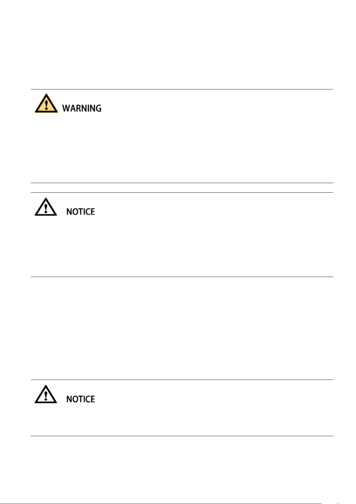
Symbol
Explanation
Indicates a dangerous situation that, if not avoided, will result in death or
serious injury
Indicates a dangerous situation that, if not avoided, will result in death or
serious injury
Indicates a dangerous situation that, if not avoided, may result in minor or
moderate injury
Indicates that if property damage is not avoided
Draw attention to important information, best practices and tips
NOTE is used to address information that is not related to personal injury,
equipment damage, and environmental degradation.
Any contact with copper bar, contactor and terminal inside the device or connected with the loop of utility
grid might result in burning or fatal electric shock.
Don’t touch any terminal and conductor connected with the loop of utility grid.
Pay attention to any instruction and safety documents about power on-grid.
2 Safety Precautions
2.1 Symbols
2.2 Important Safety instructions
This user’s manual is about installation and operation of Sinexcel PWS1 series 50kW to 250kW Bi-directional
Energy Storage Inverter (PCS).
Before installation, please read this user’s manual carefully.
The PCS must be commissioned and maintained by the engineers designated by the manufacturer or the
authorized service partner. Otherwise, it might endanger personal safety and result in device fault. Any
damage against the device caused thereby shall not be within the warranty scope.
The PCS cannot be used for any circumstance or application related to life support device.
This manual contains important instruction for Models of PWS1 series that shall be followed during
installation and maintenance of the PCS.
6
There might be an electric shock risk inside the device!
Any operation related to this device will be conducted by professionals.
Pay attention to the safety precautions listed in safety instruction and installation documents.
Pay attention to the safety precautions listed in operating and installation manual and other documents.
Large leakage current
Before connecting input power supply, please ensure that the grounding is reliable.
The device must be grounded complying with the local electric codes.
When storage battery is connected to PCS, there may be DC voltage at input port. Please pay attention to it
during operation or check the battery system user manual
Don’t touch electric parts within 15 minutes after power outage!
There is dangerous energy in capacitance storage. Don’t touch device terminal, contactor and cooper bar
and other electric parts within 15 minutes after disconnecting all device power supplies.
All maintenance and preservation inside the device require using tools and shall be conducted by trained
person. The components behind the protective cover plate and dam board which are opened by tools cannot
be maintained by users.
Please read this user’s manual before operation.
2.3 Additional Information
Links to additional information can be found at http://sinexcel.us/ or www.sinexcel.com.
7

3
1
2
3
1
2
Position
Designation
1
Indicator light
2
EPO (Emergency Power Off)
3
HMI(Touch Screen)
3 Product Introduction
3.1 System Introduction
The [PWS1 series 50K~250K Bi-directional Storage Inverter (PCS)] is a battery power conversion system
that converts the DC (direct current) supplied by a battery into grid-compliant AC (alternating current). An
[internal] low voltage transformer fitted downstream feeds the AC (alternating current) into the utility grid.
This kind of PCS can be used in the on-grid mode and off-grid mode. The model with STS can get the faster
switching between on-grid and off-grid mode.
The [PWS1 series 50K~250K Bi-directional Storage Inverter (PCS)] can be used in off-grid systems based on
diesel generators (Gensets).
3.2 PCS Appearance
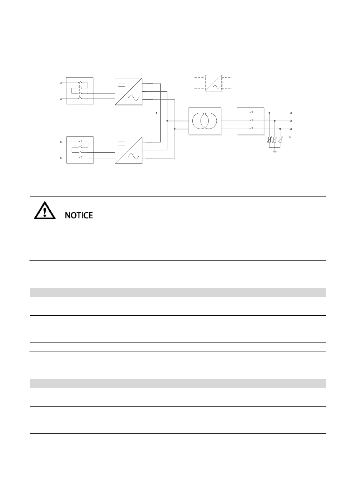
3.3 System Schematic Diagram
PWS1-50K/100K/150K/250K Bi-directional Storage Inverter (PCS) is composed of 1 or multiple set(s) of
PCS-AC modules. The modules identify master-slave systems through the DIP switch dial-up codes on the
panel. #1 is a master system, while other modules track the master system. The Bi-directional Storage
Inverter (PCS) cabinet is equipped with SPD protector, AC/DC breaker and distribution units. If on/off-grid
Figure3- 1: Design of the PCS
8

switching is to be achieved, extra power distribution unit needs to be added. Figure below is a topological
DC Switch
Battery
-
L
1
L
2
L
3
N
Transformer
AC Switch
AC SPD
PCS-AC, n=1~3
·······
PCS-AC 1
PCS-AC n
Grid
DC Switch
Battery
-
L
1
L
2
L
3
N
Transformer
AC Switch
AC SPD
PCS-AC, n=1~3
·······
PCS-AC 1
PCS-AC n
U
V
W
STS switching
model
(Optional)
AC Switch
(Optional)
Grid
Load
L
1
L
2
L
3
N
Transformer
AC SwitchDC Switch 1
AC SPD
Battery
-
PCS-AC, n=1~5
·······
PCS-AC 1
PCS-AC n
Grid
graph for its composition and structure.
Fig. 3-2 Topological graph for PWS1-50K to 150K series Bi-directional Storage Inverter (PCS) without STS
module
Fig. 3-3 Topological graph for PWS1-50K to 150K series Bi-directional Storage Inverter (PCS) with STS
module
9
DC Switch n
Battery
-
DC Switch 1
Battery
-
…
…
…
…
PCS-AC 1
PCS-AC n
DC Switch, n=1~4
L
1
L
2
L
3
N
Transformer
AC Switch
AC SPD
PCS-AC, n=1~4
Grid
Both models have identical mechanical and electrical construction except composed of different sets of
PCS-AC modules and rating:
For PWS1-250K series is composed of 4 sets of PCS-AC modules, the special model with different number of
DC branch switches from 1 to 4.
Serial No.
Item
Quantity
Remark
1
Cabinet
set
The cabinet is equipped with distribution
components.
2
PCS-AC module
1~3set(s)
50Kw 1 set; 100Kw 2 sets; 150Kw 3 sets;
3
Isolation transformer
1set
4
Power Management Unit
1 set
It is installed in the cabinet door.
Serial No.
Item
Quantity
Remark
1
Cabinet
set
The cabinet is equipped with distribution
components.
2
PCS-AC module
5 set(s)
4 sets for the 4 branch DC input switch model;
3
Isolation transformer
1set
4
Power Management Unit
1 set
It is installed in the cabinet door.
Fig. 3-4 Topological graph for PWS1-250K series Bi-directional Storage Inverter (PCS) with 1 branch input
Fig. 3-5 Topological graph for PWS1-250K series Bi-directional Storage Inverter (PCS) with 4 branch input
Main composition of PWS1-50K to 150K series PCS rack is shown in Table.3-2.
Table 3-2 Main composition of the PCS rack
Main composition of PWS1-250K series PCS rack is shown in Table.3-2.
Table 3-3 Main composition of the PCS rack
10
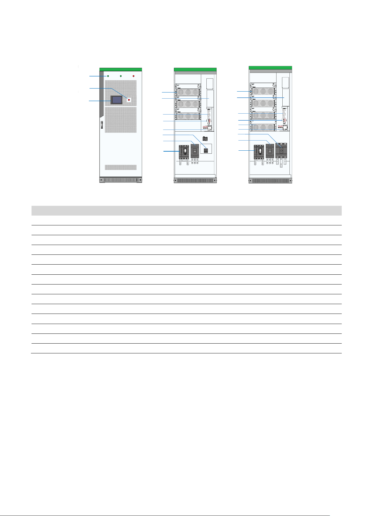
3.4 PCS Composition
3
1
2
5
4
11
7
9
10
6
12
5
4
10
7
8
9
6
11
12
Position
Designation
Description
1
Indicator lights
2 EPO (Emergency Power Off)
3 Touch Screen
4 PCS-AC (1~3 module(s))
50KW 1 set; 100KW 2 sets; 150KW 3 sets;
5
U2 Main Control Board
6 Wiring Terminal
Digital Input and Digital Output
7
AUX power supply switch
8 STS module
Switching device; Only for the models with STS
9
SPD switch
10
Manual Soft Start Switch
Only for the models without STS
Or
AC breaker (Grid)
Only for the models with STS
11
AC breaker (Grid)
Only for the models without STS
Or
AC breaker (Load)
Only for the models with STS
12
Battery switch
Figure3-6: Visible Components of the PCS without STS module with STS module
For PWS1-50K to 150K series
Components position 6 Wiring Terminal, 7 AUX power supply switch, 9 SPD switch, can be seen after unfold
the dam-board.
11

3
1
2
6
8
10
7
5
4
11
9
Position
Designation
Description
1
Indicator lights
2 EPO (Emergency Power Off)
3 Touch Screen
4 PCS-AC (1~5 module(s))
62.5KW 1 set
5
Manual Soft Start Switch
Only for the models without STS
6
AUX Power supply switch
7 SPD switch
8 AC Switch
9 U2 Main control board
10
Battery DC Branch Switch
1 to 4 set DC Branch Switch
11
Wiring terminal
Figure3-7: Visible Components of the PCS without STS module
For PWS1-250K series
Components position 6 AUX power supply switch, 7 SPD switch, 11 Wiring Terminal can be seen after unfold
the dam-board.
12
3.5 Operating Compositions
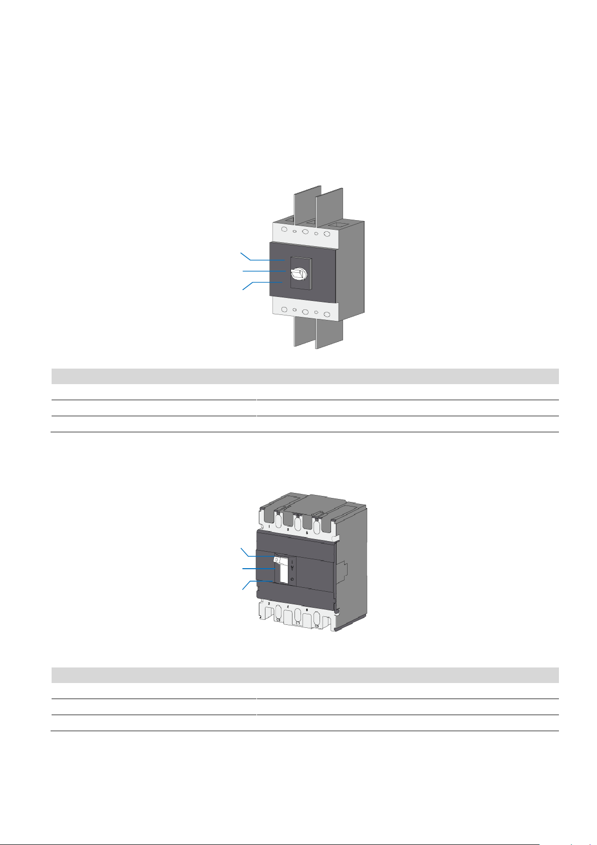
I
O
▽
Position
Designation
Explanation
I
Switch position In (On)
The AC disconnection unit is closed.
▽
Central switch position
The AC disconnection unit was tripped and is open.
O
Switch position off
The AC disconnection unit is open.
I
O
▽
Position
Designation
Explanation
I
Switch position In (On)
The DC disconnection unit is closed.
▽
Central switch position
The DC disconnection unit was tripped and is open.
O
Switch position off
The DC disconnection unit is open.
3.5.1 Switches Introduction
3.5.1.1 AC switch
The AC disconnection unit disconnects the PCS from the Grid. The NA series PCS breaker is comply to the UL
certification.
Figure 3-8: Switch positions of the AC disconnection unit
3.5.1.2 DC Switch
The DC disconnection unit disconnects the PCS from the Battery module arrays. The NA series PCS breaker
is comply to the UL certification.
Figure 3-9: Indicators on the DC load-break switch
13

3.5.1.3 AUX power supply AC Switch
AUX power supply switch
SPD switch
AUX power supply switch
SPD switch
220Vac AUX power supply can be the redundancy power supply through the AC Switch inside the PCS
cabinet. These switches can be visible after opening the dam-board.
Figure 3-10: PWS1-50K/100K/150K AUX power supply AC Switch and SPD switch
3.5.2 Touch Screen
3.5.2.1 User Interface
The touch display is used to display instantaneous values and parameter settings. Click the touch screen
with fingernail. Tapping the symbols on the touch display activates the corresponding functions. If the touch
display has not been touched for 【ten】 minutes, the display is locked and the logged-in user will be logged
out. By tapping the screen unlock the display again.
The touch display is divided into two areas.
Figure 3-11: PWS1-250K AUX power supply AC Switch and SPD switch
14

A
B
C
Figure 3-12 UI Design of the touch display
Position
Designation
Explanation
A
Menu
Menu can be different before/after log-in and other setting.
B
System Topology
C
Version and time
Symbol
Designation
Grid
Load in AC side
DC side
STS Module
Transformer (Inside)
AC
DC
AC Module
Switch on DC or AC side open
Switch on DC or AC side closed
3.5.2.2 Symbols Explanation
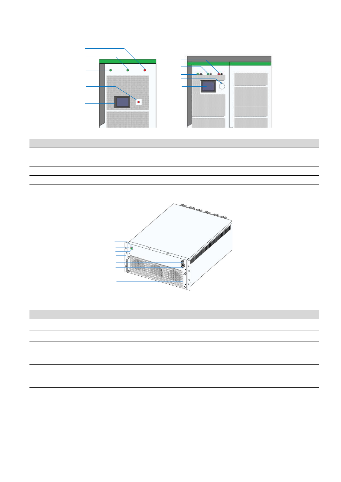
3.5.3 LEDs of the System
The appearance of the PCS is shown in below. Front door body is mainly composed of touch screen, normal indicator light,
alarm indicator light and emergency shutdown button etc.
15
5
3
4
2
1
3
2
1
5
4
Figure 3-13 LEDs on the front panel
LED designation
Description
Explanation
1
Fault indicator light
2 Normal indicator light
3
Power indicator light
4
Emergency shutdown button
5 Touch screen
1
2
4
5
7
6
3
LED designation
Description
Explanation
1
Normal indicator light
Green
2
Fault indicator light
Red
3
DIP switch
Address
4
Hanger
5
Power supply socket
6
Communication cable socket
7
Handle
Can’t bearing too much weight
Figure 3-14 Front view for PCS-AC module
16
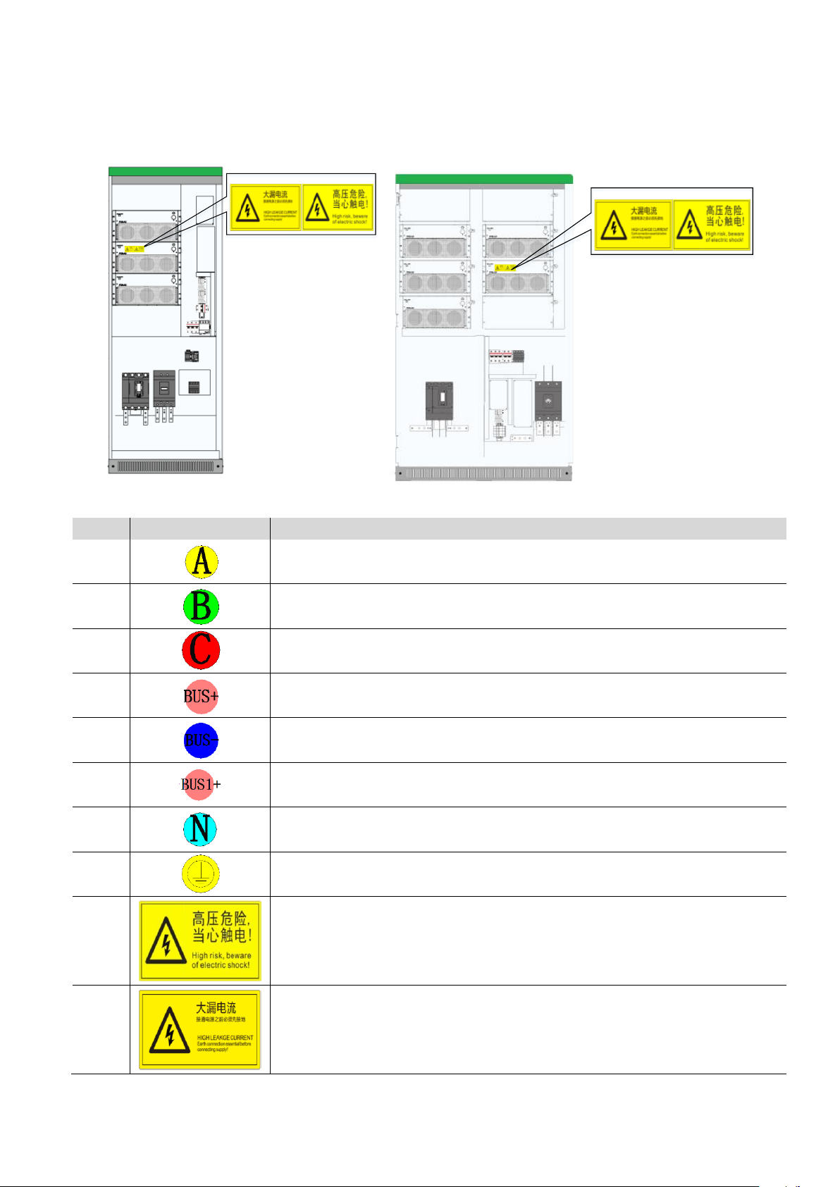
3.5.4 Labels
No.
Label
Explanation
1
Label-Dot label-A phase
2
Label-Dot label-B phase
3
Label-Dot label-C phase
4
Label-Dot label-Negative electrode
5
Label-Dot label-Negative electrode
6
Label-Dot label-Negative electrode
7
Label-Dot label-Neutral line
8
Label-Dot label-Grounding
9
Label-Warning label-Danger High Voltage
10
Label-Warning label-Danger large leak current
Figure 3-15 Warning label position
17

4 Technical Data
Model
PWS1-50K
PWS1-100K
PWS1-150K
PWS1-250K
Utility-interactive Mode
Battery voltage
range
500~850V
500~850V
500~850V
500~850V
DC max current
110A
220A
330A
550A
Quantity of
battery strings
1/4/8
AC voltage
480V(423V~528V)
480V(423V~528V)
480V(423V~528V)
480V(423V~528V)
AC current
60A
120A
180A
301A
Nominal power
50kW
100kW
150kW
250kW
AC frequency
60Hz(59.5~60.5Hz)
THDi
≤3%
AC PF
Listed: 0.8~1 leading or lagging (Controllable)
Actual: 0.1~1 leading or lagging (Controllable)
Stand-alone Mode
Battery voltage
range
500~850V
500~850V
500~850V
500~850V
DC Max Current
110A
220A
330A
550A
AC output
voltage
480V(±10% configurable)
AC output current
60A(Max 66A)
120A(Max 132A)
180A(Max 198A)
301A(Max 331A)
Nominal AC
output power
50kW
100kW
150kW
250kW
AC max power
55kW
110kW
165kW
275kW
Output THDu
≤2%(Linear load)
AC frequency
60Hz
AC PF
Listed: 0.8~1 leading or lagging (Load-depend)
Actual: 0.1~1 leading or lagging (Load-depend)
Overload
Capability
105%~115% 10min;
115%~125% 1min;
125%~150% 200ms
Physical
Cooling
Forced air cooling with replaceable fan module
Noise
70dB
Enclosure
IP20/NEMA1
IP20
IP20
IP20
Max elevation
3000m/10000feet (> 2000m/6500feet derating)
Operating
ambient
-20°C to 50°C (De-rating over 45°C)
Technical parameters for the models with transformer
18

temperature
Humidity
0~95% (No condensing)
Size (W× H× D)
800*2160*800mm
800*2160*800mm
800*2160*800mm
1200*2160*800mm
31.5*85*31.5
inches
31.5*85*31.5
inches
31.5*85*31.5
inches
47.2*85*31.5
inches
Weight
465kg
680kg
910kg
1280kg
Installation
Vertical installation
Other
Peak efficiency
95.50%
95.80%
96.10%
96.10%
CEC efficiency
94%
94%
94.5%
95%
Protection
OTP, AC OVP/UVP, OFP/UFP, EPO, AC Phase Reverse, Fan/Relay Failure, OLP,
GFDI, Anti-islanding
Configurable
protection limits
Upper/Lower AC Voltage/Frequency limit, Battery EOD voltage.
AC connection
3-Phase 4-Wire+PE
Display
Touch Screen
Communication
RS485,CAN,Ethernet
Isolation
Built-in Transformer
Certification
ETL listed conforming to UL1741/UL1741SA, UL9540,CPUC RULE 21,IEEE1547,
HECO RULE14H,CEC,CSA22.2,HECO CGS,HECO CSS
Application environment restrictions:
When the Battery Energy Storage System is working in stand-alone mode (off-grid mode), there are some
restriction to the application environment.
• Several PCS AC output parallel is the customized function. Please contact manufacture when user need the
AC output parallel in off-grid mode.
• Resistive load power < PCS rated power
• RCD (Resistive Capacitor Diode) load power < PCS rated power * 80%, and meanwhile RCD load
power<100KW. When the RCD load >100KW, please contact the manufacture and customize the PCS.
• Motor load with Frequency Converter, load power < PCS single machine rated power * 80%
• Motor load without Frequency Converter, please contact the manufacture and customize this PCS function.
19
5 Storing, lifting and transporting
If the lifted or suspended load falls over, falls or sways, there is a risk of crushing
Vibration or careless or hasty lifting and transport can cause the product to tip over or fall. This can result in
death or serious injury.
All national transport standards and regulations must be respected.
Always transport the product as close as possible to the floor.
Avoid fast or uneven movement during transport.
Always maintain a sufficient safety distance from the product during transportation.
Damaged frame structure of the PCS due to uneven support surface
Placing the PCS on an uneven surface can cause bending, which causes the PCS door to no longer close
properly.This can cause moisture and dust to seep into the PCS.
Do not place the PCS on an unstable, uneven surface, even for short periods of time.
The unevenness of the support surface must be less than 0.25%.
Do not use the installed kick plate to transport the PCS.
During rack transport and storage, stacking is not allowed. The device top cannot be placed with other
articles.
The rack should be placed vertically at forward direction. Don’t keep it upright placed horizontally.
More detailed shipping and installation information can be found in the Installation Manual.
5.1 Safety during Transport
5.2 Transporting the PCS
5.2.1 Transport and storage
The module of the PCS are installed in the PCS cabinet rack during shipping. During device transport and
storage, pay attention to the caution sign on the packing case.
The selection of storing position should ensure that:
• There is no corrosive gas around it.
• There are over-wetting and high-temperature sources.
• It is not a dusty environment.
• It complies with the local firefighting requirements.
5.3 Unpacking the PCS
More detailed Transporting Unpacking the PCS can be found in the Installation Manual.
20

6 Installation
Risk of electric shock caused by live voltage
There is a high voltage in the live components of the product. Touching field components can result in death
or seriousness electric shock damage.
Wear appropriate personal protective equipment for all work on the product.
Do not touch any live components.
Observe all warning messages in products and documents.
Obey all safety information from the battery manufacturer.
Electric shock hazard caused by DC cable
The DC cable connected to the battery is live. Contact with live cables can cause electrocuted death or
serious injury shock.
Before connecting the DC cable, make sure that the DC cable has no voltage.
Wear appropriate personal protective equipment for all work on the product.
Danger to life due to electric shock when entering the storage system
Damage to the insulation in the storage system can result in fatal ground currents. May cause a fatal electric
shock. Ensure that the insulation resistance of the storage system exceeds the minimum.
Minimum value:The insulation resistance is: 14kΩ.
The PCS must be installed in a closed electrical operating area.
Fire due to failure to observe torque specifications at real-time bolt connections
Failure to comply with the specified torque reduces the current carrying capacity of the live bolt connection,
thereby reducing the contact resistance increase.
This can cause the components to overheat and catch fire.
Be sure to always tighten the live bolt connection using the exact torque specified in this document.
Use only the right tools when working on the device.
Avoid repeatedly tightening the live bolt connection as this may result in unacceptably high torque.
More detailed shipping and installation information can be found in the installation manual.
6.1 Safety during Installation
21
 Loading...