

sinercom LION100K, LION120K User Manual

LION SERIES
DSP Controlled UPS
100-120 kVA
3 Phase In - 3 Phase Out
Sinercom srl
Headquarter: Via G. Cappalonga 9/A- 00043 Ciampino (Rm) (Italy)
tel. +39.06.79800323 fax +39.06.79814644
Factory: Via Cascina Secchi 247/4b - 24040 Isso (BG)
tel. +39.0363.938231 fax +39.0363.998235
USER MANUAL


CONTENTS
I. GENERAL DESCRIPTION ...................................................................................... 3
1.1 Introduction ....................................................................................................... 3
1.2 Design Concept ................................................................................................ 5
1.2.1 Description of Blocks ............................................................................... 6
1.2.2 Operating Conditions of UPS………………………………………………...6
1.3 Front view of UPS Conditions of ups ................................................................. 7
1.4 Technical Specifications .................................................................................... 8
II. UPS INSTALLATION .............................................................................................. 9
2.1. Introduction ....................................................................................................... 9
2.2. Unpacking ......................................................................................................... 9
2.3. Equipment Positioning ...................................................................................... 9
2.4. Connecting the UPS Power Cables ................................................................... 10
2.5. Safety Earth ...................................................................................................... 10
2.6. Cable Connection Procedure ............................................................................ 10
2.6.1. Description of Connection Terminals of the UPS ....................................... 11
2.7. Battery Installation ............................................................................................ 12
III. FRONT PANEL ....................................................................................................... 14
3.1. Introduction ....................................................................................................... 14
3.2. Front Panel Menu Descriptions ......................................................................... 14
3.2.1 MEASUREMENTS menu ........................................................................... 17
3.2.2 ALARM LOGS menu .................................................................................. 20
3.2.3 INFORMATION menu ................................................................................ 20
3.2.4 OPTIONS menu ......................................................................................... 21
3.2.5 COMMAND menu ...................................................................................... 24
3.2.6 TIME menu................................................................................................. 24
3.2.7 SERVICE menu ......................................................................................... 25
3.2.8 ADJUST menu ........................................................................................... 25
3.2.9 User Pasword ............................................................................................. 26
3.3. Alarms and warning messages ......................................................................... 26
3.4. Alarm messages and quick troubleshooting ...................................................... 29

1
IV. OPERATING INSTRUCTIONS ................................................................................ 34
4.1 Introduction .......................................................................................................... 34
4.2 Operating ups in online mode .............................................................................. 34
4.2.1 Starting ups from a completely shut down position ..................................... 34
4.2.2 Shutting down the ups ................................................................................ 34
4.2.3 Switching the UPS from a normal
operation to maintenance bypass condition .............................................. 35
4.2.4 Switching the UPS from a maintenance
bypass condition to normal operation ....................................................... 35
4.3 UPS Behavior During mains outage .................................................................. 35
V. MAINTENANCE ....................................................................................................... 36
5.1 Scheduled maintenance .................................................................................... 36
5.2 Daily checks ..................................................................................................... 36
5.3 Weekly checks .................................................................................................. 36
5.4 Annual Maintenance .......................................................................................... 37
5.5 Storage conditions and transportation of ups ..................................................... 37
VI. FAULTS AND TROUBLESHOOTING .................................................................... 38
6.1. General Procedure for fault checking and troubleshooting ................................ 38
6.2. Before calling service ........................................................................................ 38
VII. UPS REMOTE MANITORING AND CONTROL .................................................... 39
7.1. Using Serial Port ............................................................................................... 39
7.2. Serial Communication port connection cable ..................................................... 39
7.3. Modem connection ............................................................................................ 40
7.3.1 Hardware configuration ............................................................................... 40
7.3.2 Functioning Principle .................................................................................. 40
7.3.3 Modem Programming Procedure ................................................................ 40
7.3.3.1 Smart modem (SM) programming ................................................... 40
7.3.4 Modem – UPS Connection Cable ............................................................... 41
7.4. Dry contact (ınterface) connections ................................................................... 41
7.5. Remote monitoring panel connection of UPS .................................................... 41
VIII. EFFICIENT USAGE OF UPS IN TERMS OF ENERGY CONSUMPTION ............. 42

2
SAFETY
IMPORTANT NOTICES
1. Read instructions carefully before installing and starting the UPS.
2. All warnings in the manual should be adhered to.
3. All operating instructions should be followed.
4. The unit should be supplied by a grounded outlet. Do not operate the unit without a ground source.
5. Power cables of the UPS should be routed carefully so that they are not to be walked on.
6. Please save this manual.
7. Please save or recycle the packaging materials.
WARNING!
Do not insert any object into ventilation holes or other openings.
To reduce the risk of fire or electric shock, install in temperature and humidity controlled
indoor area free of conductive contaminants.
To reduce the risk of fire, replace fuses with the same type and rating when necessary.
CAUTION!
Only qualified personnel should install or service UPS/batteries.
Risk of electric shock, do not remove cover. No user serviceable parts inside, refer
servicing to qualified service personnel.
The output may be energized even when the unit is not connected to a mains supply.
Risk of electric shock! Hazardous live parts inside. This unit is energized from the
battery supply even when the input AC power is disconnected.
To reduce the risk of electric shock, disconnect the UPS from the mains supply before installing
a computer interface signal cable. Reconnect the power cables only after signaling interconnections have
been made.
CAUTION !
Units are designed to operate on the concrete floor.
ABOUT THE BATTERIES
CAUTION: RISK OF ELECTRIC SHOCK!
The battery circuit is not isolated from the mains voltage. Hazardous voltages may
occur between the battery terminals and the ground!
A battery can present a risk of electric shock or burn from high short circuit currents. The
following precautions should be taken when working on batteries :
* Remove watches, rings or other metal objects.
* Use tools with insulated handles.
The batteries in this UPS are recyclable. Batteries must be disposed of according to local
environmental laws. The batteries contain lead and pose a hazard to the environment and human health
if not disposed of properly.
Do not dispose of batteries in a fire. The batteries may explode. Do not open or mutilate the
batteries. They contain an electrolyte which is toxic and harmful to the skin and eyes. If electrolyte
comes into contact with the skin the affected area should be washed immediately.
The internal energy source (the battery) cannot be de-energized by the user.
When changing batteries, install the same number and same type of batteries.

3
I. GENERAL DESCRIPTION
1.1 Introduction
SINERCOM LION Series Uninterruptible Power Supplies are double-conversion; on-line
UPS’s manufactured with the latest IGBT and PWM technology, to produce an uninterruptible,
fully DSP (Digital Signal Processor) controlled pure sine wave output to critical loads.
SINERCOM LION Series units are 3-phase in/3-phase out devices, and they are installed
between a three phase critical load, and a 3-phase+N mains supply
The advantages of using LION UPS:
Power blackout protection:
If the mains power fails, the UPS continues to supply the critical load using the energy
stored in its batteries, keeping the load immune from power disturbances.
Increased power quality:
The UPS has its own internal voltage and frequency regulating software, which
ensures that, its output to the critical load is maintained within close tolerances, independent of
voltage and frequency variations on the mains power lines.
Fully digital control by three DSP controller for each UPS:
The UPS is controlled by 3 independent DSP chips which are communicating each
other continuously. Rectifier, Inverter and User Interface modules have separate DSP’s to
achieve the highest performance. Each DSP module has many parameters to control and
monitor the system to have the best electrical power output and to help diagnostic.
Increased noise rejection:
By rectifying the input AC power to DC power and then converting it back to AC
(Double-Conversion) any electrical noise present on the input mains supply line is effectively
isolated from the UPS output. Therefore the critical load is supplied with only clean and
uninterrupted AC power.

4
Basic Features:
PWM and IGBT technology
Pure sinusoidal output wave form and true on-line topology
High input power factor (IGBT rectifier), Input current limiting
Low input current THD (IGBT rectifier)
Low output voltage THD
High AC/AC and DC/AC efficiency (up to 94%)
3 separate DSP (Digital Signal Processor) control
Cold-start feature
Static By-Pass feature: Provides uninterruptable transfer to bypass source in case of overload
Bypass leakage current sense system
Maintenance bypass switch and warning system, by-pass short circuit protection
Separate bypass input facility (split bypass), generator operation sense input
LCD alphanumeric display panel providing battery, load, voltage, power and status information
Improved diagnostics and correct fault infor mation
Up to 192 event memory record system (7000 alarms or warnings total)
Real time clock and calendar system
Overload operation 10 minutes at 100% - 125% load, 1 minute at 125% - 150% load
Output overload, over-current and short circuit protection, output current limiting
Reliable operation at even 100% unbalanced load condition
Non-linear load supply feature (CF 3:1)
Double polarity battery (with common terminal)
Automatic and manual battery test and battery temperature compensation features
3 separate maintenance clock counters
Battery charge with current limiting
Automatic and manual boost charge feature
Battery deep discharge protection
Temperature protection with 3 separate sensors
Interactive communication
Diagnostic and settings with PC ability
2 separate RS232 communication ports (standard)
Multi UPS monitoring on same communication line by RS485 (optional)
4 dry contact alarm relay outputs as standard (8 optional relay outputs)
Improved remote monitoring panel system (optional)
RS232 port multiplexer (optional)
Direct network connection with optional SNMP support
MODBUS Adapter (optional)
AT command set definitions for dump modems
Communication via Windows based T-MON software and remote monitoring and control of UPS
Optional softwares compatible for most computer platforms
Ability for labeling of UPSs by users
Emergency power-off support
Conformity to international and local standards
AC input and output filters
Optional graphic front panel
CE compliance
Input, bypass and load phase order protection
Optional leakage current alarm system
Input and output isolation transformers (optional)
Enhanced accessory options
100.000 hours MTBF
2 years system warranty
10 years spare parts warranty
or UPS fault.
in detail to user
via modem

5
(F10
-
F11-F12)
1.2 Design Concept
3 PHASE
MAINS I/P
S1 (F1-F2-F3) : Rectifier Input Switch / Fuse
S2 (F4-F5-F6) : Bypass Input Switch / Fuse
S3 : Maintenance Bypass Switch
S4 (F7-F8-F9) : Output Switch / Fuse
S5 (F10-F11-F12) : Battery Switch / Fuse
K1 : Rectifier Input Contactor
K2 : Inverter Output Contactor
S3
Maintenance
Bypass Switch
S2
(F4-F5-F6)
S1
(F1-F2-F3)
K1
-
Rectifier /
Charger
Battery
(Dual Polarity)
SB
Static
Bypass
-
Inverter
S5
K2
S4
(F7-F8-F9)
3 PHASE
AC Output

6
1.2.1 DESCRIPTION OF BLOCKS
RECTIFIER: In LION Series UPSs, a DSP controlled IGBT rectifier with PWM technique is used to increase
input power factor (PFC) and to decrease input current harmonics (THDI).
The IGBT rectifier accepts 3-phase AC input and produces a dual polarity DC voltage for both supplying the
inverter and charging the batteries.
BATTERIES: Batteries are used as reserve DC power supply for the Inverter in case of mains failure. In LION
Series, batteries are connected in series with a center-tap output to obtain a dual polarity DC supply.
Batteries are discharged by the inverter during mains failure. The discharged batteries are re-charged by the
IGBT Rectifier on a constant voltage / current limiting basis, if AC mains power is available.
INVERTER: It is manufactured by using the latest IGBT and DSP (Digital Signal Processing) technologies,
and Pulse Width Modulation (PWM) technique. The Inverter converts the DC BUS voltage supplied by the
IGBT Rectifier and / or the batteries into a well regulated, fully digital controlled 3-phase AC voltage with fixed
voltage and frequency.
The output of the inverter is used to supply the critical loads connected to the UPS output.
STATIC TRANSFER SWITCH (STATIC BYPASS): This is an electronically controlled transfer switch, which
enables the critical load to be connected either to inverter output or to by-pass power source. During normal
operation, the load is supplied by the inverter output, but in case of an overload or a UPS failure it is
automatically transferred to the bypass source without any interruption.
MAINTENANCE BYPASS SWITCH (MBS): This is a manually controlled mechanical switch, which is used to
supply the critical load, using the bypass source, when the UPS is shut down for maintenance or
troubleshooting purposes.
The load is unprotected against mains supply disturbances and black-outs when it is connected to either static
or maintenance bypass supply.
1.2.2. OPERATING CONDITIONS OF UPS
UPS may be in one of the following operating conditions:
A. Normal Operation (If Mains supply is available):
All fuses and power switches are closed (except the Maintenance Bypass Switch), and the load is supplied by
the Inverter Output. During normal operation, the Rectifier supplies DC power to the Inverter and charges the
Batteries at the same time.
B. Battery Operation :
The Batteries are connected to the Rectifier output. In case of a mains failure (mains power outage or AC
input voltage out of tolerance), the Rectifier stops operating and the DC voltage necessary for the inverter
operation is supplied by the batteries. Therefore the AC voltage output supplying the critical load is not
interrupted, until the batteries are fully discharged. At the end of the discharging time the inverter is turned off
and it start again automatically, together with the rectifier, when the mains power is restored, and the UPS
returns o normal operation. For UPS with a split bypass source, at the end of discharging time, static transfer
switch transfers the load to the split bypass source without interruption if the split bypass source is available
and in acceptable tolerances about voltage and frequency, as still the rectifier input is not available.
The Rectifier is also turned off and inverter operates on batteries during automatic or manual battery test
procedure.
C. By-Pass Operation :
If the Inverter output is overloaded or in case of a problem in the UPS, the static switch transfers the load to
the bypass supply without any interruption, provided that the bypass supply is available and within the
tolerated limits regarding voltage and frequency. At the end of the overloading period, if the fault condition is
restored, static switch transfers the critical load again to the inverter output. Note that, during operation from
the bypass supply, the critical load may be effected by any possible disturbances or power failure in the
bypass supply.
7
S7
S1
S3
S2
S4
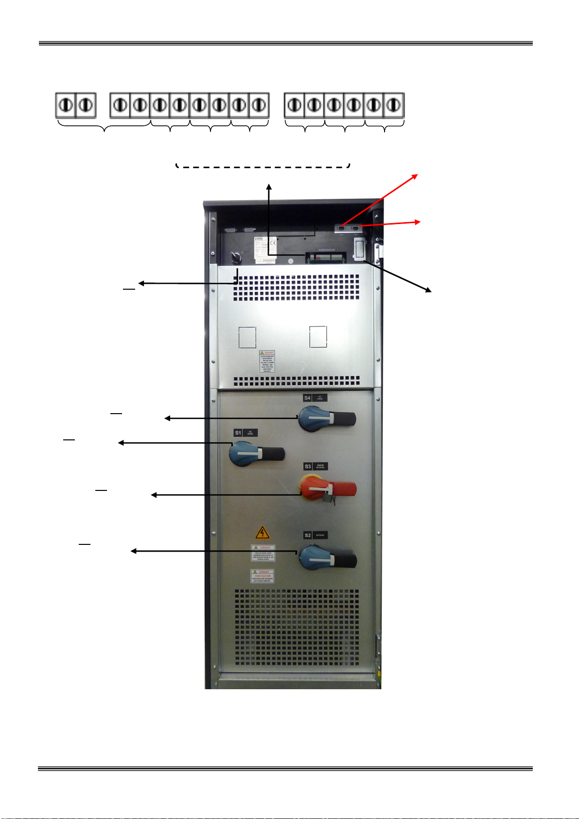
1.3 Front view of UPS Connection Panel
Batt. circuit
breaker
output
and input
(AC output, F7-F8-F9)
(AC input, F1-F2-F3)
(maintenance by-pass’ı)
(By-Pass, F4-F5-F6)
Generator
On/off
switch
Figure 1.3 a 100-120 kVA Switches, Fuses and Interface Connections
input
Emergency
Temperature
sensor
stop
Relay Output contacts
Relay
2
Relay
3
Relay
4
COM1 - RS232
Communation Socket
(DB9 female)
COM2 - RS232
Communation Socket
(DB9 female)
SNMP
(Optional)

8
1.4 Technical Specifications
2.
MODEL LION100K LION120K
Output (KVA) 100 kVA 120 kVA
Output (KW) 90 kW 108 kW
Output Power Factor 0,9
INPUT
Number of Phases 3 Phase + Neutral
Input Voltage 220/380, 230/400 or 240/415 Vac
Input Voltage Tolerance +20% , -25% (+15% at 240/415Vac)
Input Power Factor (PF) 0,98 - 0,99 (at full load)
Input THDI <= 5% (at full load)
Input Frequency
By-pass Voltage 220/380, 230/400 or 240/415 Vac 3 Phase + Neutral
By-pass Frequency
RFI Level EN62040-2
OUTPUT
Number of Phases 3 Phase + Neutral
Output Voltage 220/380, 230/400 or 240/415 Vac
Output Voltage Tolerance
Output Frequency 50 Hz.
Output Frequency Tolerance (Synchronous)
Output Frequency Tolerance (Battery)
Efficiency (100% Load) up to 94%
Load Crest Factor 3:1
Output Voltage THD (linear load) <3%
Overload 125% Load 10min. , 150% Load 1min.
BATTERY
Total Number 60 blocks 12V (2x30 serial 60 batteries, external)
Float Charge Voltage (250C)
End of Discharge Voltage
Battery Test Automatic and Manual
Boost Charge Available
COMMUNICATION INTERFACES
RS232 Com Port 2 each standard (COM1 and COM2)
External Temperature Measurement Input Available (standard)
RS485 Comm. Port Optional
Remote Monitoring Panel Optional
SNMP Adapter Optional
Modbus Adapter Optional
Alarm Relay Contacts 4 each dry contacts (function programmable) 8 optional
Digital Inputs 2 each optional
Emergency Power-Off Input Available (standard)
50 Hz. 5%
50 Hz. 2%
1%
2%
0,2%
405V DC
300V DC
ENVIRONMENT
Operating Temperature 0 – 400C
Operating Humidity <= %90 (non-condensing)
Acoustic Noise < 68 dB
Dimensions (WxDxH) (mm) 515 x 855 x 1450
Device Type and Protection Class Class 1 – IP20
Weight (app. kgs) 216 230
3.

9
II. UPS INSTALLATION
2.1 Introduction
WARNING!!!
Do not apply electrical power to the UPS equipment before the arrival of authorized service personnel.
The UPS equipment should be installed only by qualified service personnel.
The connection of the batteries and the maintenance should be done by qualified service personnel.
Do not make any short- circuit to the battery poles. Because of high voltage and high short-circuit current,
there is risk of electrical shock or burn.
Eye protection should be worn to prevent injury from accidental electrical arcs. Remove rings, watches and
all metal objects. Only use tools with insulated handles. Wear rubber gloves.
This chapter contains location installation information of the UPS and the batteries. All the establishments
have their own specialties and needs. So in this part, the installation procedure is not being explained step by
step. Instead, general procedure and the applications are explained for the technical personnel.
2.2 Unpacking
The UPS is packed and enclosed in a structural cardboard carton to protect it from damage.
1) Inspect for damage that may have occurred during the shipment If any damage is noted, call the shipper
immediately and retain the shipping carton and the UPS.
2) Carefully open the carton and take the UPS out.
3) Retain the carton and packing material for future use.
Unit package contents:
1) A user manual and Guarantee certificate.
2) Battery cabinet and/or shelf (Optional)
3) Battery connection cables.
2.3 Equipment Positioning
ATTENTION: Units are designed to operate on the concrete floor.
1. The equipment’s installation place must be an easy serving place.
2. Install the UPS in a protected area with adequate air flow and free of excessive dust.
3. You must therefore allow for a minimum gap of 250 mm behind the unit to allow adequate air flow
4. Select a suitable place (temperature between 0C and 40C) and the relative humidity (%90 max)
5. It is recommended to place the equipment in an air-conditioned the room (24C)
6. Temperature is a major factor in determining the battery life and capacity. Keep batteries away from main
heat sources or main air inlets etc.
7. In case of an operating the UPS in a dusty place, clean the air with a suitable air filtration system.
8. Keep out of your equipment from explosive and flammable items.
9. Avoid direct sunlight, rain, and high humidity.
WARNING!!! Check the capacity of the forklift if it is available for lifting.
DO NOT LEAN OR LIFT THE UPS CABINET AFTER THE BATTERIES HAVE BEEN
INSTALLED.

10
2.4 Connecting the UPS Power Cables
WARNING!!! A separate power line should be used to supply the UPS AC input. Never use the same line to
supply another electrical device. Do not use any additional cable to increase the length of the
UPS’s input cable. It is advised to use an MCCB suitable for the input current on the UPS’s
input line.
The connection of the electrical panel should be supplied by a grounded outlet. Otherwise, the UPS and
the load connected to the output will be left ungrounded. The grounding system must be
checked, and must be strengthen if required. Potential difference between ground and neutral
must be less than 3V AC.
Descriptions of the UPS input output cable connection terminals are shown in figure 2.1
Recommended input line cable and fuse ratings are given in the table below.
UPS power
(kVA)
100 50 35 35
Recommended cable size (mm2)
Line input
Bypass input /
UPS output
External Battery
Input / output
Cable connections
U-V-W-N
M8 bolt M8 bolt
Battery
connections
+ & -
120 50 50 50
M8 bolt M8 bolt
NOTES: The neutral conductor should be sized for 1,5 times the output/bypass phase current. These
recommendations are for guideline purposes only and are superceded by local regulations and
codes of practice.
2.5 Safety Earth
The safety earth cable must be connected to the earth BUS BAR and bonded to each cabinet in the system and
also the earthing and neutral bonding arrangements must be in accordance with the local laws.
ATTENTION!!! Failure to follow adequate earthing procedures can result in electric shock hazard to
personnel, or the risk of fire.
2.6 Cable connection procedure
WARNING!!! All connections of the UPS must be done by qualified service personnel
After positioning the UPS, the cables must be connected as described below:
1. Verify all switches and fuses in front of the UPS are at “0” position. (OFF)
2. Connect the 3 phase AC input coming from the mains distribution panel to the AC input terminals as shown
on the label. (Figure 2.1)
ATTENTION!!!: ENSURE CORRECT PHASE SEQUENCE.
If there is a phase sequence error, UPS doesn’t transfer the load to INVERTER output. If you
can’t see SYNC:OK in the INFORMATION MENU on LCD, then change the input phase sequence.
3. Connect the output of the UPS to the load distribution panel.
4. Connect the battery groups. Refer to battery installation section.
WARNING :
- CHECK BOTH OF THE BATTERY GROUPS FOR CORRECT POLARITY AND VOLTAGE
- DO NOT TURN ON THE BATTERY SWITCH (F5) BEFORE STARTING THE UPS
11
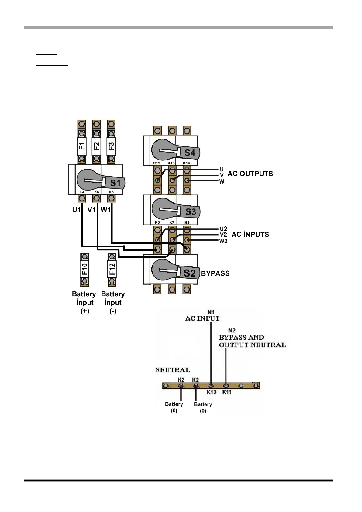
Figure 2
.
2
100-120 kVA
POWER
Cable Connection
5. Connect the copper earth bus, to the safety earth of the mains distribution panel.
NOTE : The earth and the neutral connections must be in accordance with the local rules.
WARNING: Note that the Input Neutral (N1) MUST also be connected to K10 terminal
2.6.1 Description of connection terminals of the UPS :
 Loading...