

Page 1

1
Preface
Thank you for purchasing EA100 series servo drive.
EA100 is a high performance general-purpose servo drive, which can be widely used in the numerically controlled machine
tools, printing and packaging machinery, textile machinery, robot automatic production line and other automation fields.
Since SINEE is committed to the development and improvement of products and products documents, this manual will be
updated without notice.
Page 2
2
Safety Information
Danger: The label indicates that a failure to follow instructions can result in
serious injury or even death.
Caution: The label indicates that a failure to follow instructions can result in moderate or slight injury and device damage.
Please read this chapter carefully before system installation, debugging and maintenance and always follow the safety precautions below during
operation. SINEE will not undertake any damage or loss caused by a failure to follow the instructions.
Safety Precautions
Before Installation:
Danger
1. Do not install servo drive if its package is wetted or any its component is missing or
broken.
2. Do not install servo drive if the label information on its package is not identical to that on
servo drive.
Caution
1. Be careful when carrying or transporting servo drive so as to avoid damage!
2. Do not use servo drive if it is damaged or any component is missing so as to avoid
injury!
3. Do not touch the parts of control system with bare hands so as to avoid ESD!
During Installation:
Danger
1. Installation base shall be metal or other non-flammable material so as to prevent fire risk.
Caution
1. Ensure that no cable strips or screws are dropped servo drive so as to avoid damage to
servo drive.
2. Install servo drive at a place with less vibration and no direct sunlight.
3. Consider the installation space for cooling purpose when servo drive is installed in a
closed cabinet or space.
Wiring:
Danger
accidents.
risk.
applicable wiring standard so as to avoid electric shock.
Caution
attention to terminal symbols and connect to the terminals correctly so as to prevent risks of
damaging servo drive.
recommended sizes so as to prevent accident risk.
Otherwise, it will trigger the action of the overcurrent protection circuit or even damage the
internal parts of servo drive.
parts of servo drive.
Page 3
3
Before Power-on:
Danger
L2 and L3 and output terminals U, V or W are correctly connected, there are no short
circuit phenomena for the wiring of servo drive and its peripheral circuits, and all wires are
in good connection. Otherwise, this may result in servo drive damage.
factory. Otherwise, this may result in accident.
Caution
may result in an electric shock.
manual. Otherwise, it may result in an electric hazard.
After Power-on:
Danger
1. Do not touch servo drive or its peripheral circuits with wet hands to avoid the electric
shock.
2. If the indicator is off or the keypad does not display any information after power-on,
please cut off the power supply immediately. Never touch any terminal of L1, L2 or L3 of
servo drive or the connecting terminals with hands or a screw driver, or else an electric
shock accident may occur. Contact our customer service personnel immediately after
cutting off the power.
3. After being powered on, servo drive will automatically check the safety of the external
strong circuit automatically. Therefore, do not touch wiring terminal U, V or W of servo
drive or the wiring terminal of the motor with bare hands, otherwise it will result in electric
shock.
Caution
running so as to avoid accidents.
During Operation:
Danger
temperature, which may result in burning!
personal injury or device damage.
Caution
avoid damage to the device.
damage to the device.
injury..
Maintenance:
Danger
shock.
indicator is off. Otherwise, the residual electric charge of capacitor may result in personal
injury.
avoid personal injury or device damage.
performed after power-off.
Attentions
Page 4

4
Varistor or Power Factor Improvement Capacitor on Inverter Output
Servo drive outputs PWM wave. Do not use servo drive, if a power factor improvement capacitor or a lightning varistor is on output side, which
may easily result in transient overcurrent of servo drive, or even damage servo drive.
Surge Protection
A surge protection device is installed in servo drive to prevent it from induction lightning stroke on a certain degree. Additional protection
devices are required in front of servo drive in the places where thunder and lightning occur frequently.
Altitude and Derating
When servo drive is used in an area at an altitude of over 1,000m, the cooling effect will degrade, so it must be derated. For details, please
consult SINEE.
Attentions at Servo Drive Scrapping
Burning the electrolytic capacitors of the mains and PCB may result in explosion and burning plastic parts may generate toxic gas. Please handle
them as industrial wastes when servo drive is scrapped.
Page 5

5
CONTENT
1 Product Information .............................................................................................................. 6
1.1 Verifying Product .......................................................................................................... 6
1.2 Model Numbering Scheme and Nameplate ................................................................... 6
1.3 Model Number List ....................................................................................................... 7
1.4 Servo Drive Control Mode ............................................................................................ 7
2 Installation .............................................................................................................................. 8
2.1 Caution .......................................................................................................................... 8
2.2 Storage ambient conditions ........................................................................................... 8
2.3 Installation ambient conditions ...................................................................................... 8
2.4 Servo Drive Installation Direction and Space ................................................................ 8
2.5 Servo Motor Installation Direction and Space ............................................................... 9
2.6 Circuit breakers and fuse recommendations ................................................................ 10
2.7 Brake resistance selection ............................................................................................ 10
2.8 EMI Filters .................................................................................................................. 12
3 Display & Operation ............................................................................................................ 13
3.1 Display and key operation Exterior ............................................................................. 13
3.2 Display and operation mode ........................................................................................ 13
3.3 Parameter setting Description ...................................................................................... 13
3.4 Status Display .............................................................................................................. 14
3.5 Monitor display ........................................................................................................... 14
3.6 Fault and alarm display ............................................................................................... 14
4 Wiring ................................................................................................................................... 15
4.1 Peripheral connection .................................................................................................. 15
4.2 Main circuit wiring ...................................................................................................... 15
4.3 CN5 encoder signal terminal ....................................................................................... 18
4.4 CN4 Control signal terminal ....................................................................................... 20
4.5 CN2, CN3 communication terminal wiring ................................................................. 31
4.6 CN1 analog output terminal ........................................................................................ 31
4.7 Holding brake .............................................................................................................. 32
4.8 Standard wiring diagram for control circuit................................................................. 34
4.9 Control circuit wiring precaution ................................................................................ 36
4.10 Servo drive main circuit block diagram ..................................................................... 36
5 Running and debugging ....................................................................................................... 38
5.1 Drive power on ................................................................................................ ............ 38
5.2 Trial running ................................................................................................................ 38
5.3 Servo enable method ................................................................................................... 38
5.4 Speed control mode ..................................................................................................... 39
5.5 Torque control mode debugging steps ......................................................................... 40
5.6 Gain parameter adjustment strategy ............................................................................ 40
6 Function Parameters ................................................................................................ ............ 42
6.1 Function parameters define ......................................................................................... 42
6.2 Function parameter list ................................................................................................ 42
7 Function parameter details .................................................................................................. 54
7.1 P0 group - Monitoring parameters ............................................................................... 54
7.2 P1-xx Basic control parameters ................................................................................... 58
7.3 P2-xx Internal multi segment position (Pr) control parameter ..................................... 74
7.4 P3-xx Internal multi-speed control parameters ............................................................ 76
7.5 P4-xxTorque control parameter ................................................................................... 76
7.6 P5-xx Gain tuning parameters ..................................................................................... 77
7.7 P6-xx Input and output(DI/DO)parameter ................................................................... 82
7.8 P7-xx Communication parameters .............................................................................. 87
7.9 P8-xx Auxiliary check even-parity function parameters .............................................. 88
7.9 Pb-xx the origin of regression function parameters ..................................................... 91
8 Communications protocol .................................................................................................... 96
8.1 Application Scope ....................................................................................................... 96
8.2 Physical interface ........................................................................................................ 96
8.3 Protocol format ............................................................................................................ 96
8.4 Command interpretation .............................................................................................. 96
8.5 Protocol Format Description ....................................................................................... 97
8.6 Example....................................................................................................................... 98
9 Fault alarm and Treatment ................................................................................................. 99
9.1Fault Diagnosis and Treatment ..................................................................................... 99
9.2 Alarm Diagnose and Treatment Measures ................................................................. 102
10 Specification ...................................................................................................................... 104
10.1 Technical specification ............................................................................................ 104
10.2 Dimensions .............................................................................................................. 105
10.3 Motor specification .................................................................................................. 106
10.4 SER series servo motor dimension .......................................................................... 108
10.5 SER series servo motor overload characteristics ..................................................... 110
Page 6
6
1 Product Information
1.1 Verifying Product
Check and verify the product:
Item
Method
Check if they are identical to the
purchase order.
Check the nameplate at the side of inverter.
Any damage.
Check the overall appearance to see if they are
damaged in transportation.
Any loosened screws or other
fastening parts.
Check with a screw driver if necessary.
If you find any quality problem, please contact SINEE Direct Sale Department or the distributor.
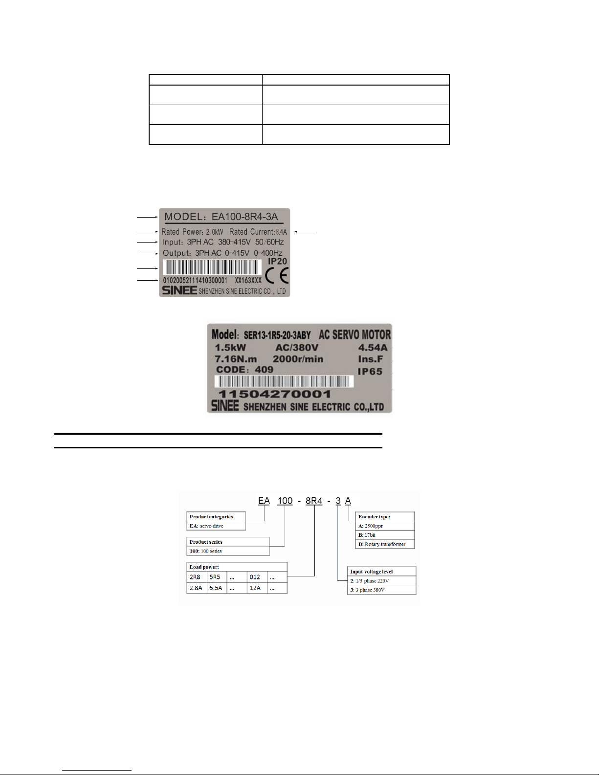
1.2 Model Numbering Scheme and Nameplate
1.2.1 Nameplate
EA100 series servo drive
产品型号
适配电机功率
电源规格
输出规格
产品条码
产品序列号
额定输出电流
SER series servo motor
NOTE:The actual product nameplate may be different from as shown in the figure.
1.2.2 Model Numbering Scheme
Servo drive:
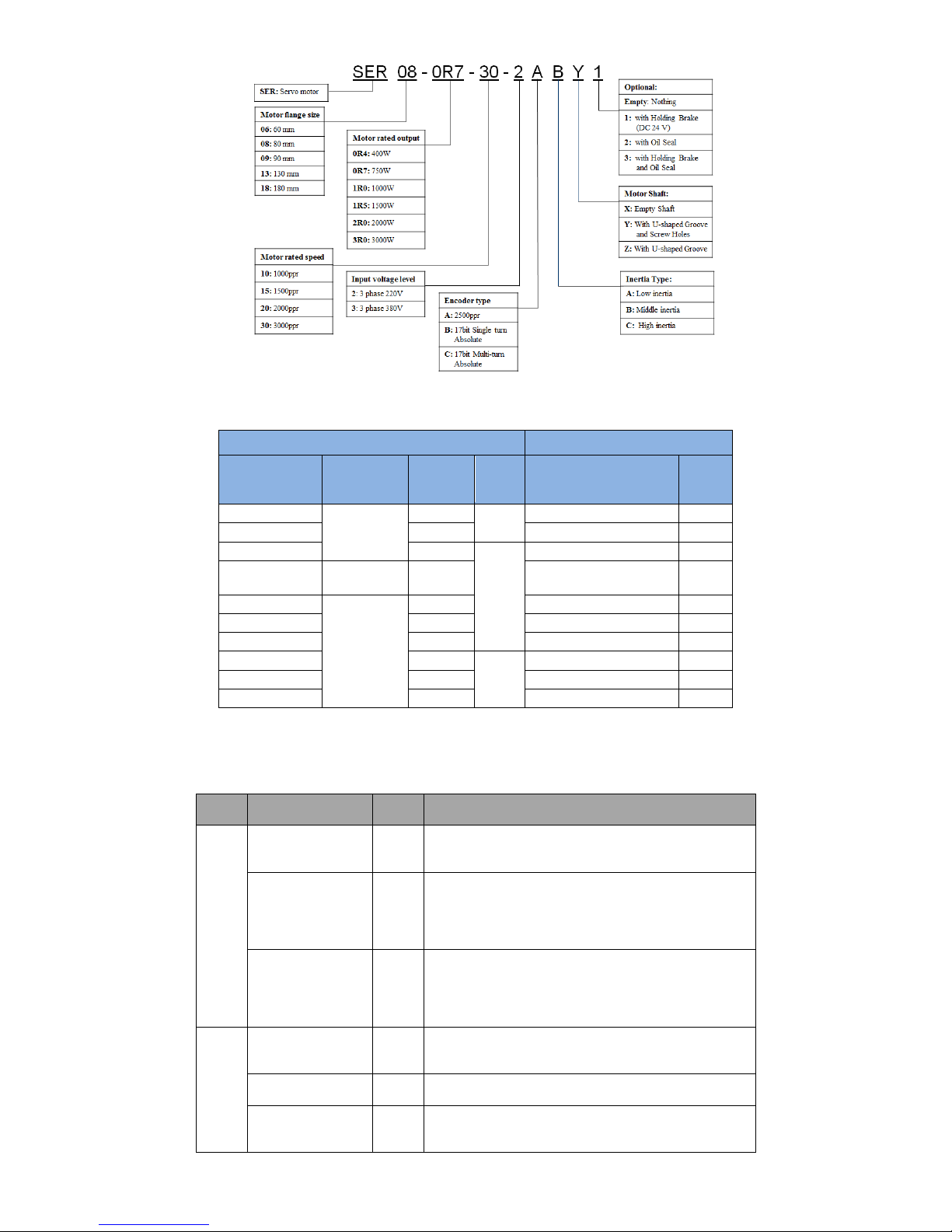
Servo motor:
Page 7
7
1.3 Model Number List
Servo Drives
Matched Servo Motors
Model of servo
drives
Input voltage
Rated
output
current
Size
Model of servo motors
Motor
power
EA100-2R8-2A
1/3 phase AC
220V
2.8A
SIZE A
SER06-0R4-30-2AAY
400W
EA100-5R5-2A
5.5A
SER08-0R7-30-2AAY
750W
EA100-7R6-2A
7.6A
SIZE B
SER13-1R0-20-2ABY
1000W
EA100-010-2A
3 phase AC
220V
10.0A
SER13-1R5-20-2ABY
1500W
EA100-5R4-3A
3 phase AC
380V
5.4A
SER13-1R5-20-3ABY
1500W
EA100-8R4-3A
8.4A
SER13-2R0-20-3ABY
2000W
EA100-012-3A
12.0A
SER13-3R0-20-3ABY
3000W
EA100-018-3B
18.0A
SIZE C
SER18-4R5-15-3BBZ
4500W
EA100-021-3B
21.0A
SER18-5R6-15-3BBZ
5600W
EA100-030-3B
30.0A
SER18-7R5-15-3BBZ
7500W
1.4 Servo Drive Control Mode
The drive can provide multiple control modes for users, please refers to as follows:
Type
Control mode and
function parameter
Display
Specification
Single
mode
Position mode
P1-00=1
P
Drive accepts position command to control motor
Running at target position.
Position command input by terminal, signal is pulse.
Speed mode
P1-00=0
S
Drive accepts speed command to control motor running to
targer speed.
Speed command can be provided by internal register (3
groups) or analog voltage input terminal, and confirm which
use at present based on DI.
Torque mode
P1-00=2
T
Drive accepts torque command to control motor
running to target torque.
Torque command can be provided by internal register (3
groups) or analog voltage input terminal, and confirm which
use at present based on DI.
Mixed
mode
Speed and Position
switch mode
P1-00=3
S-P
S and P can switch by DI terminal.
Torque and Position
Switch mode P1-00=5
T-P
T and P can switch by DI terminal.
Speed and Torque
switch mode
P1-00=4
S-T
S and T can switch by DI terminal.
Page 8
8
2 Installation
2.1 Caution
Please pay special attention to the following:
The cable between servo drive and servo motor should stay relaxed, not tense.
If the cable between servo drive and servo motor is more than 20 meters, please
Strengthen UVW connection and encoder connection.
When the servo driver is fixed, the installation direction must be in accordance with the regulations, and each fixed screw must be locked.
For the determination of concentric with the servo motor shaft and equipment shaft, to
prevent the radial stress when motor running.
Four fixed screws of the servo motor must be locked according to the prescribed torque.
In order to make the cooling effect better, when install AC servo drives, the upper and lower, left and right and adjacent items and baffle
(wall) must keep enough space, otherwise it will cause fault.
When the servo driver is installed, it can not be dumped. The air suction and exhaust holes are not blocked, otherwise, the fault can be
caused.
2.2 Storage ambient conditions
Please put the product in its packing box before installation. If the drive is not used, in order to enable the product to meet the company's
scope of warranty and future maintenance, be sure to pay attention to the following conditions:
2.3 Installation ambient conditions
2.3.1 EA100 servo drive using ambient conditions:
Item
Description
Dust and gas
No dust, free of corrosive gas or liquid.
Ambient humidity
Relative humidity 20%~90%(no condensation)
Ambient temperature
0℃~+45℃
Vibration
Below 4.9m/s²
Impact
Below 49m/s²
Elevation
Below 1000m,please derating above 1000m
2.3.2 SER series servo motor using ambient conditions:
Item
Description
Ambient humidity
Relative humidity20%~80% (no condensation)
Ambient temperature
0℃~+40℃
Vibration
Below 4.9m/s²
Impact
Below 49m/s²
Elevation
Below 1000m,please derating above 1000m
Do not use motor in closed ambient. Closed ambient will lead to high temperature of motor, shorten the service life.
2.3.3 Other caution
In addition to the above ambient conditions, regardless of the drive or motor, when selecting the installation site, please observe the
following precautions,otherwise, may make the product can not meet the company's warranty coverage and future maintenance:
No high temperature.
No water drops, steam, dust and oil dust.
No corrosive or flammable gas or liquid.
No floating fiber or metal particles.
Installation base shall be solid and free from vibration.
No electromagnetic interference and away from interference source.
2.4 Servo Drive Installation Direction and Space
Servo drive and servo motor appearance size and weight specifications, please refer to the chapter 10.
2.4.1 Method
Please ensure the installation direction and walls are vertical. To use natural convection or fan for cooling of the servo drive. Through the
mounting hole, the servo driver is firmly fixed on the mounting surface.
When installing, please turn the servo drive front (the operator's actual mounting face) to the operator, and make it perpendicular to the wall.
2.4.2 Cooling
Item
Description
Storage temperature
-20℃~+65℃(high temperature: 80℃ 72hours)
Storage humidity
Relative humidity of 0% to 95% with no condensation
Vibration
Below 49m/s²
Impact
Below 490m/s²
Page 9
9
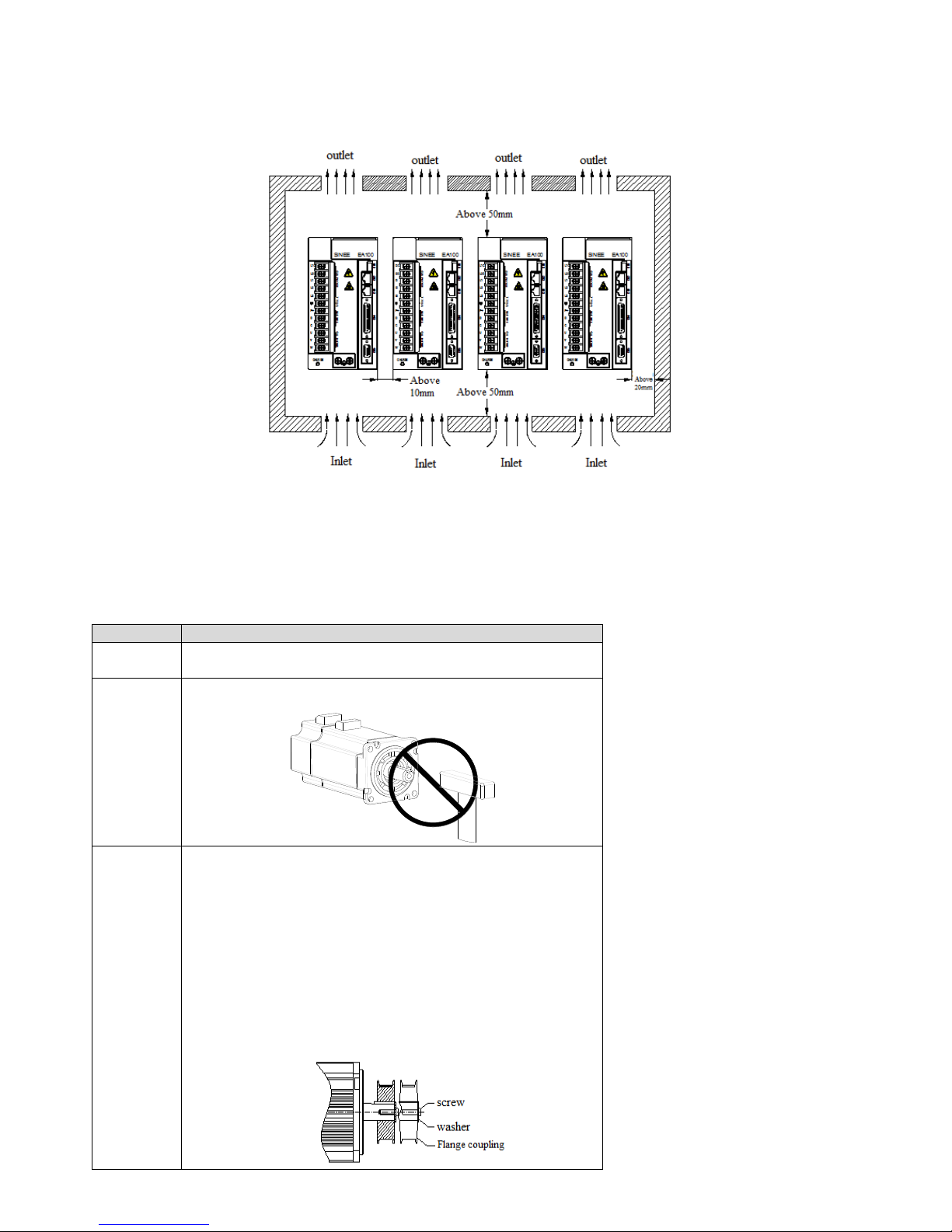
In order to ensure the air convection, please refer to Figure 2-1, around the servo drive with enough space.
In order not to make the ambient temperature of the servo drive partial excessive phenomenon, so that to maintain a uniform temperature of
electric cabinet, please install cooling fan above servo drive in electric cabinet.
2.4.3 Ground
Make sure the ground terminal is grounded, otherwise, there may be a risk of electric shock or interference arising from false action.
Figure 2-1 Servo Drive Installation Direction and Space
2.5 Servo Motor Installation Direction and Space
2.5.1 Motor installation
SER series servo motor must be installed in a dry and solid platform, please keep good ventilation and heat radiation effect, and keep a
good grounding.
2.5.2 Installation diagram
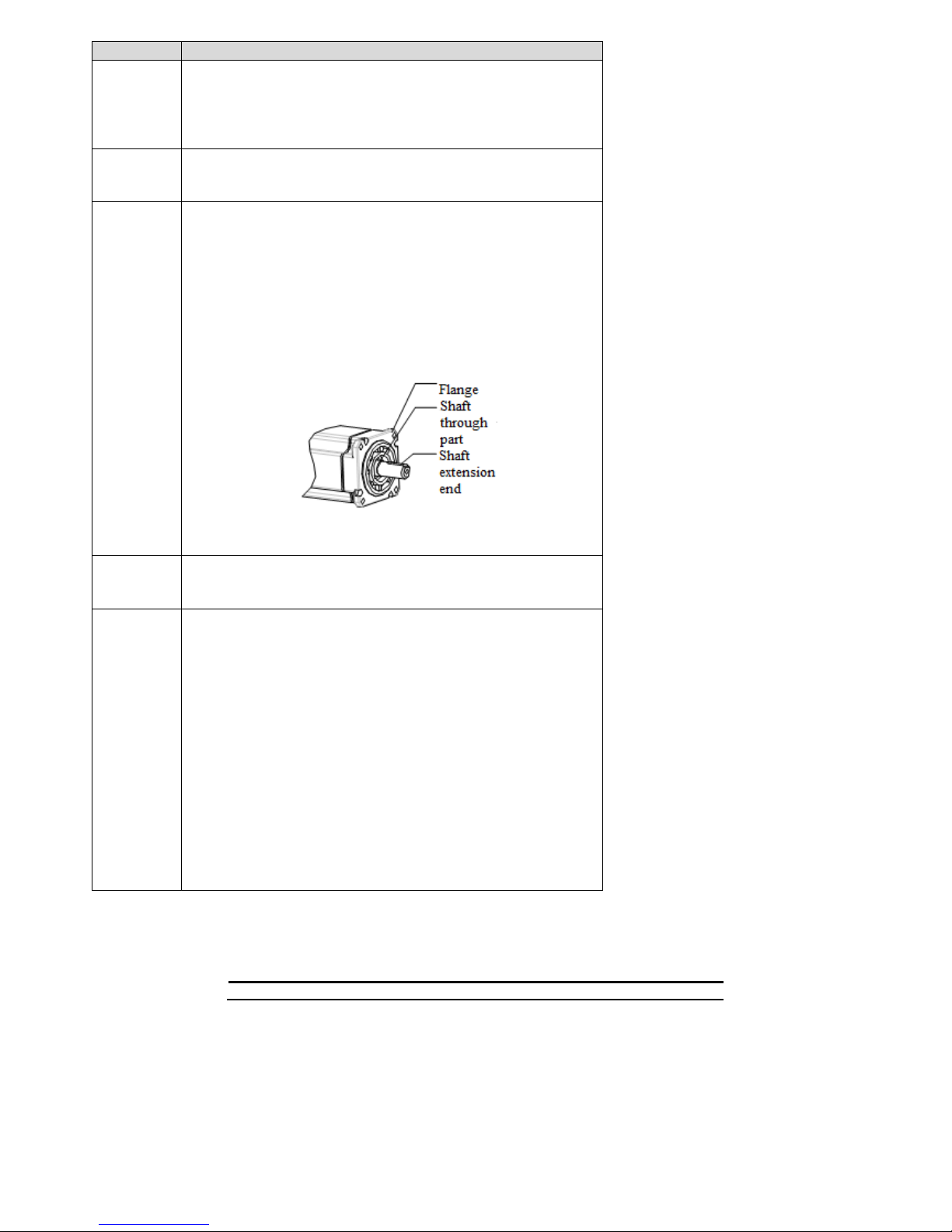
Item
Description
Anti-rust
solution
Wipe clean servo motor shaft extension ends of the "anti rust agent" before
installation, and then do the relevant anti rust treatment
Encoder note
Installation to prohibit the impact of the shaft extension end, otherwise it
will cause internal encoder fragmentation.
Pulley
installation
When installing the pulleys in the servo motor shaft with keyway ,please
use screw on the shaft end. In order to install pulley, at first, the double
headed nail is inserted into the screw hole of the shaft, washer is used on
the surface of the coupling end and a nut gradually locked into the
pulley.
About the servo motor shaft with keyway, use the screw holes of shaft
end to install. About the shaft of no keyway, adopt the wear coupling or
similar method.
When removing the pulley, adopt pulley removal device to prevent shaft
subjected to impact.
In order to ensure safety, a protective cover or similar device shall be
installed in the rotating area.
Page 10
10
Item
Description
Centering
In connection with the machine, please use the coupling, as well as the
axis of the servo motor and mechanical axis to keep in a straight line, the
circumference radial pulsation of the shaft coupling should not be
greater than 0.03mm. If the centering is not sufficient, it will produce
vibration, it can damage the bearings and encoders etc.
Installation
direction
The servo motor can be installed in horizontal direction or vertical
direction, do not install slant, otherwise it may cause motor bearing
wear.
Oil solution
When using at the place of water droplets drop , please confirm the servo
motor on the basis of the protection level (except the shaft through part).
When using for the site of oil droplets will drop to the shaft through part,
please specify the use of oil seal with the servo motor.
The servo motor operating conditions with oil seal:
Please ensure the oil level is lower than the oil seal lip when
using.
Please use when oil seal can keep oil splash in a good condition.
In the servo motor vertical installation, please pay attention not to use oil
seal.
Shaft through part: Refers to the gap of motor shaft from the end surface of the
protruding part
Stress condition
of cable
Don't make cable excessive bending or tension is applied to it, especially the
core wire of the encoder signal line is 0.12 mm or0.22 mm, very fine, so in
wiring and using, please don't make the stretching tight.
Connector parts
solution
For connector parts, please note the following:
The connector, please confirm there is no garbage or metal debris and
other foreign bodies in connector.
The connector connects to the servo motor please first from one side of
the servo motor circuit cable and cable main grounding wire must
reliable connection. If first connected one side of the encoder cable, the
encoder may be fault caused by the potential difference between the PE.
The connection, please confirm the correct pin arrangement.
The connector is made of resin. Do not apply impact to prevent damage
to the connector.
When cable maintain connection to handle, please hold the servo motor
main body. If only seize the cable handling, may be damaged or broken
cable or connector.
If you need to bend the cable, you should pay full attention to the
wiring , do not make the connector part of the pressure or tension, or
may cause the connector damage or poor contact.
2.6 Circuit breakers and fuse recommendations
If there is a drive to install the leakage circuit breaker to be used as the leakage fault protection, to prevent leakage circuit breakers
malfunction, please select the model about the sense of current in the 200mA above and the action time of 0.1 seconds above.
Fuse, please use the fast fuse model, its rated current should be based on the drive capacity of about 1.5 times.
Strongly recommended: The fuse and circuit breakers recognized by UL/CSA .
2.7 Brake resistance selection
When the motor's output torque and speed in the direction of the opposite, the energy will be transmitted back to the drive from the load.
This energy will be poured into the bus bar so that the voltage value of the bus inside the drive is increased, and the magnitude of the recharge
energy depends on the inertia of the motor and the load. If the system inertia small, may through drive internal capacitors to absorb recharge
energy, but if the system inertia is large, more than the energy that capacity absorb, voltage value may rise too high, causing the drive stop or
even damage, so when the voltage rises to a certain value, recharge energy must by a braking resistor to consume.
The following table 2-1 lists commonly used SER series servo motor rotor inertia and EA100 drive internal capacitive absorption ability, and
retrogradation energy calculation formula.
Page 11
11
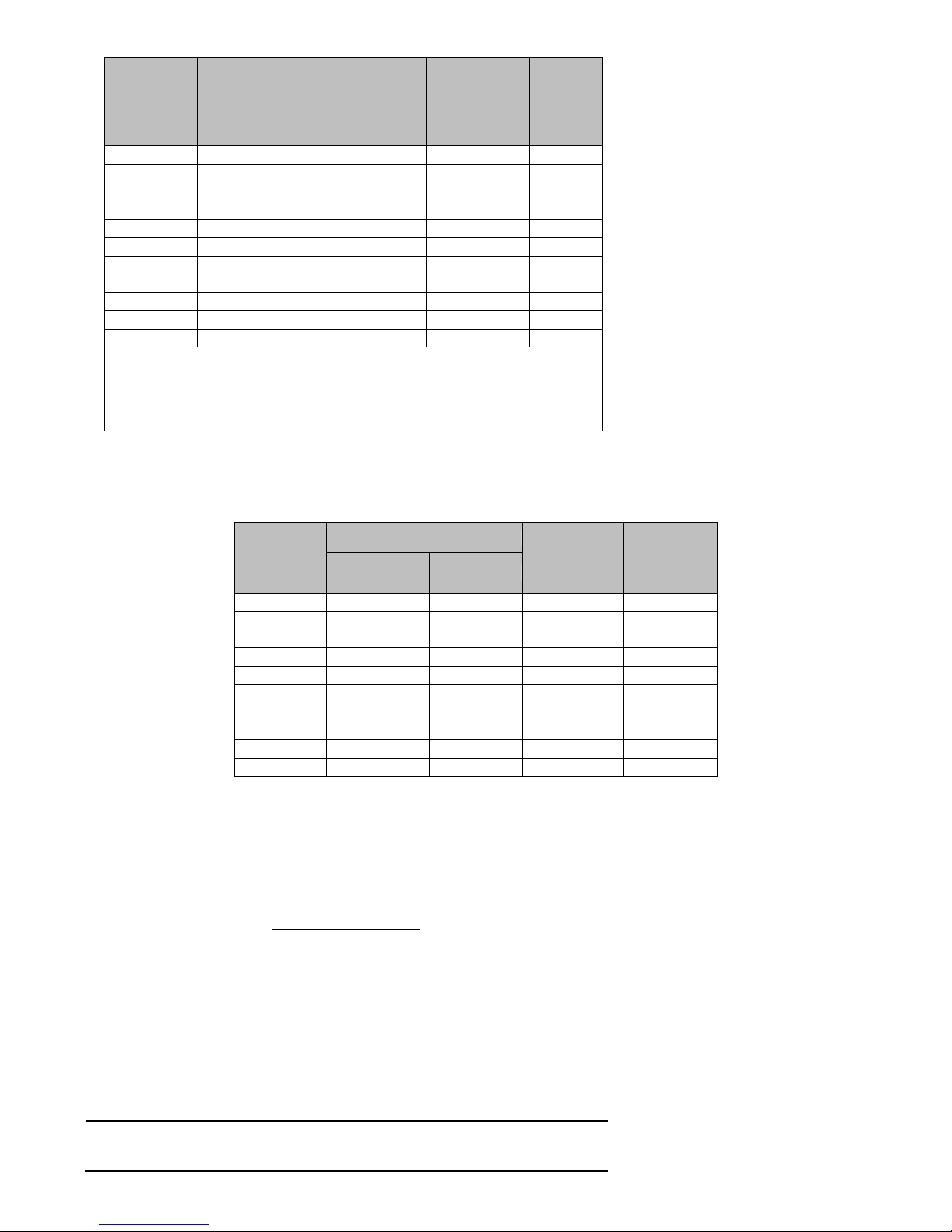
Table 2-1 SER series servo motor rotor inertia and retrogradation capacity absorbed
Model
Motor
rotor inertia
42
( 10 )J kg m
Retrogradation
from rated speed
to motionless
without load
Eo (J)
Capacity
maximum
retrogradatio
n
Ec (j)
EA100-2R8-2□
SER06-0R4-30-2□AY
0.3
1.48
16
EA100-5R5-2□
SER08-0R7-30-2□AY
1.01
4.99
24
EA100-7R6-2□
SER13-1R0-10-2□BY
17.14
9.42
41
EA100-7R6-2□
SER13-1R0-20-2□BY
8.71
19.1
41
EA100-010-2□
SER13-1R5-20-2□BY
12.08
26.5
41
EA100-5R4-3□
SER13-1R5-20-3□BY
12.08
26.5
34
EA100-8R4-3□
SER13-2R0-20-3□BY
17.14
37.67
49.6
EA100-012-3□
SER13-3R0-20-3□BY
25.58
56.22
49.6
EA100-018-3B
SER13-4R5-15-3BBZ
35.37
43.73
61.2
EA100-021-3B
SER13-5R6-15-3BBZ
45.51
56.26
91.8
EA100-026-3B
SER13-7R5-15-3BBZ
79.89
98.76
91.8
retrogradation energy calculation formula:
v:rpm,motor maximum speed
The motor rotor inertia of servo motor with brake is same with servo motor without
brake’s.
2.7.1 Built-in brake resistance
There is brake resistance in EA100 series drive, suitable for the general situation of the load inertia. About EA100 series built-in brake
resistance specifications, please refer to Table 2-2.
Table2-2 EA100 drive built-in brake resistance allowable minimum external brake resistance
Model
Brake resistance(built in)
Retrogradation
treated by built in
brake resistance
Allowable
minimum
external brake
resistance
Resistor(P8-18)
Capacity(P8-19)
EA100-2R8-2□
50Ω
100W
50W
50Ω
EA100-5R5-2□
50Ω
100W
50W
50Ω
EA100-7R6-2□
50Ω
100W
50W
40Ω
EA100-010-2□
50Ω
100W
50W
40Ω
EA100-5R4-3□
50Ω
100W
50W
50Ω
EA100-8R4-3□
50Ω
100W
50W
50Ω
EA100-012-3□
50Ω
100W
50W
45Ω
EA100-018-3B
40Ω
200W
90W
30Ω
EA100-021-3B
40Ω
200W
90W
30Ω
EA100-026-3B
40Ω
200W
90W
25Ω
2.7.2 External brake resistance capacity calculation
When the retrogradation capacity exceeded retrogradation capacity internal brake
resistance can dealt with, should use external braking resistance.
According to the calculation formula of retrogradation , assuming the load inertia is N times the inertia of the rotor of the motor, motor
from the rated speed to 0, retrogradation is (N+1) *Eo, the action cycle is T, then
Power of braking resistance
2.7.3 Note when using external braking resistance
When using external braking resistor, resistor connected to the P+ and C terminal, at the same time must remove the short circuit piece
installing between P+ and D, makes P and D two terminals in the open state.
The external braking resistance cannot be less than reported in table 2-2, otherwise it might damage the drive.
Please make the external resistor braking resistor value and the capacity set to the function parameters of drive correctly, otherwise it will
affect the execution of the function.
P8-18 (brake resistance), P8-19 (brake resistance capacity).
In the natural environment, when the braking resistor can handle retrogradation capacity (average) below the rated capacity, resistance
temperature will rise to 120℃ above(in the continuous braking condition). For security, please use the forced cooling system, to reduce
the temperature of the brake resistor; or recommend the use of braking resistor with thermo switch. The load characteristics on braking
resistance, please refer to the manufacturer.
Note:
1) Please make the external braking resistor same with the internal braking resistor, otherwise,
may lead to drive damaged.
)(182/
2
0
JJ
v
E
T
N
EE
C
))1((2
0
Page 12

12
2) When using external braking resistance, if don‘t remove the short circuit piece which is
between P and D, it may lea to drive damaged.
2.8 EMI Filters
All of the electronic equipment (including servo drives) in normal operation, will produce some high frequency or low frequency noise, and
through the conduction or radiation interference peripheral equipment. If you can match the appropriate EMI filter and the correct installation
method, the interference will be reduced to a minimum.
When the servo driver and EMI filter are installed, we can follow the installation and wiring of the contents of the manual, we can be sure that it
can meet the following specifications:
1. EN61000-6-4(2001)
2. EN61800-3 (2004) PDS of category C2
3. EN55011+A2(2007) Class A Group 1
2.8.1 EMI Filter installation caution
In order to ensure that the EMI filter can achieve maximum effect of inhibit the servo drive interference, in addition to the servo drive
according to the contents of the manual installation and wiring, still need to pay attention to the followings:
1) Servo drive and EMI filter must be installed on the same piece of well grounded metal plane.
2) Servo drive and EMI filter, please try to install the servo drive above the EMI filter .
3) All wiring will be as short as possible.
4) Metal shell of servo drive and EMI filter must be reliably connected with the metal ,surface, and the contact area between the two should be
as large as possible.
2.8.2 Selection of motor cable and installation notes
The selection and installation of the motor line is correct or not, it’s related to the EMI filter can play the greatest effect of servo drive
interference suppression.
Please note the followings:
1) The cable with isolation copper mesh (Double isolation layer is preferred).
2) The isolated copper mesh on both ends of motor line to ground in the shortest distance and the maximum contact area.
3) Motor line isolation copper mesh connects metal plane correctly, isolated copper mesh on both sides of motor line should be fixed with
U-shaped metal piping supports and metal plane.
Page 13
13
3 Display & Operation
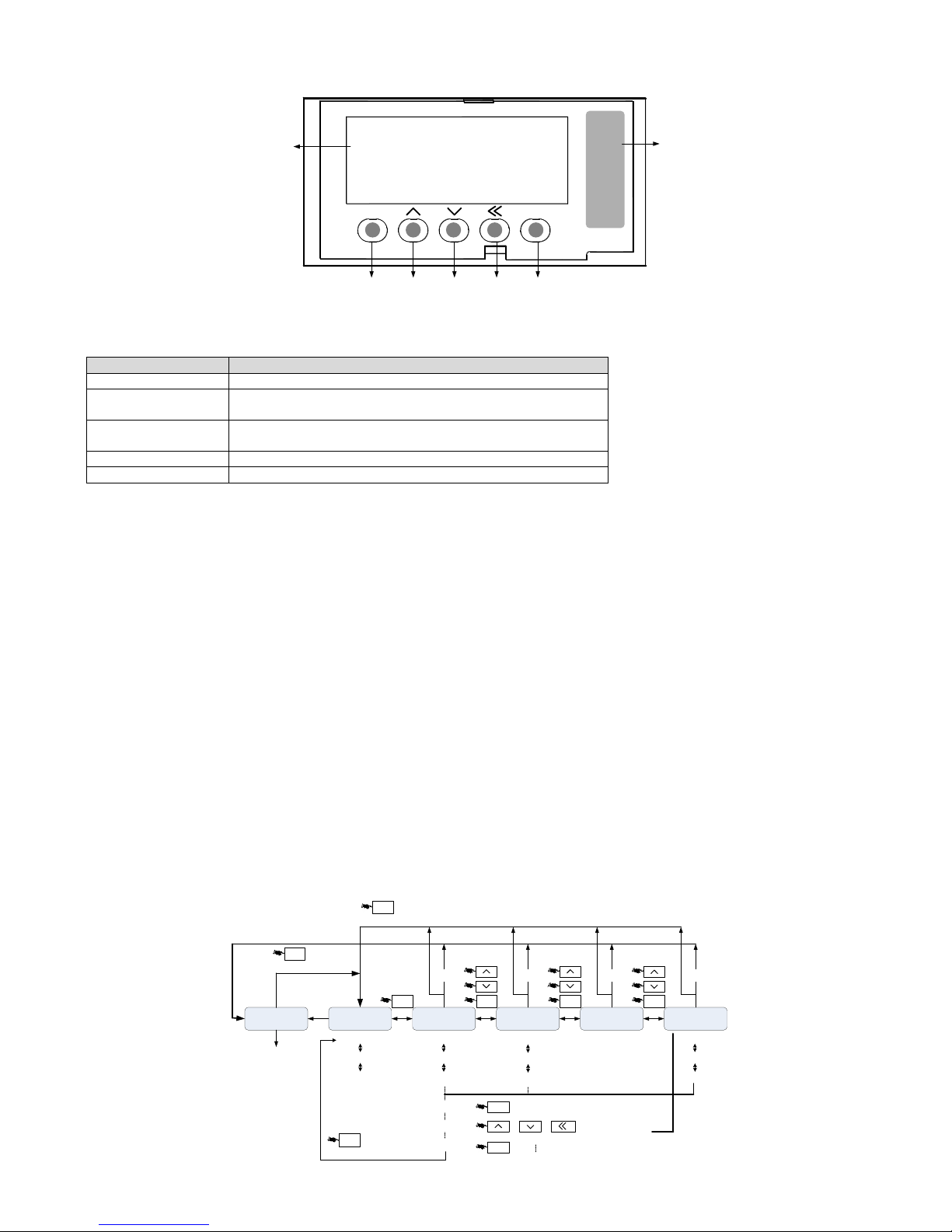
3.1 Display and key operation Exterior
Mode key
UP key DOWN key
Left key Set key
Digital display
EA100-8R4-3A
01020052111410280001
MOD SET
88888
Drive model
and serial
number
3.2 Display and operation mode
There are 5 display and operation mode for EA100 servo drive
Mode
Function
Monitor mode
Monitoring the value of parameter code
Parameter group
selection mode
Choose parameter group to be monitored or set
Parameter code
selection mode
Choose parameter code to be monitored or set
Setting Mode
Setting the value of the selected parameter code
Fault and alarm mode
Display fault and alarm information
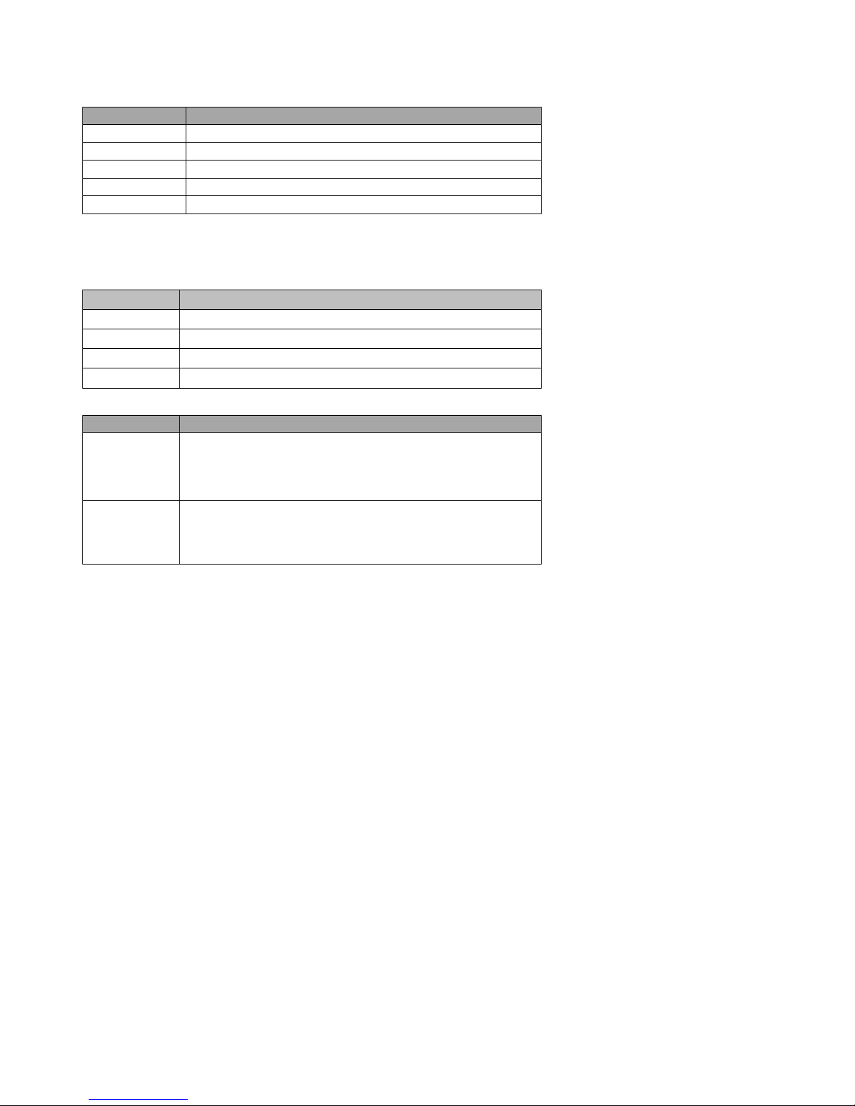
3.3 Parameter setting Description
1) When the drive is powered on, the digital tube display the default monitor code for one second, then work in monitor mode.
2) In monitor mode, pressing UP or DOWN key to change the monitored parameter code, then press the SET key to monitor selected
parameter code. If there is no key operation, it will monitor selected parameter code automatically after one minute.
3) In monitor mode, if the monitored parameter is 32 bit or displaying a more than 5 digits binary number, press the left key to switch the
display for high bit and low bit. When displaying high bit, the digital tube decimal point of the highest bit is lit.
4) In monitor mode, press MOD to enter the parameter set selection mode, then press UP / DOWN key to switch the parameter set, press the
MOD key to exit the parameter set selection mode back to monitor mode.
5) In parameter group selection mode, pressing left key, the flashing character shift left. It is easy to choose parameter group number. Press
SET key to enter parameter code selection mode, press MOD key to exit parameter code selection mode and back to parameter group
selection mode.
6) In parameter code selection mode, pressing UP or DOWN key can change the value of last two code to change parameter code, then press
the SET key immediately to enter the parameter setting mode and display the value of the parameter code.
7) In the parameter setting mode, use UP / DOWN key to set parameter. When pressing left key the blinking character will shift left, it is
easily and quickly to modify the value of the parameter high bit.
8) After setting the value, press SET key to store or execute a command.
9) After setting the value, the digital tube will display the status information of the parameter, for example, displaying -End-. Then
automatically back to parameter code selection mode.
10) In parameter setting mode, press MODE key or no key operation in one minute will cancel the modification of parameter value, and back
to parameter code selection mode.
11) When servo alarm, pressing MODE key for one second, it will show the current alarm code; pressing any key again to exit the alarm code
displayed.
Alarm display
Monitoring
parameter
Basic control
parameter
Internal multi-
location parameters
Auxiliary function
parameter
...
Or
MOD MOD
SET
Display parameter settings
SET
Storage Parameters
MOD
Double-click
or
Shift Left
Fault
Fault
Fault
Fault
Fault
MOD MOD
MOD
Double-click
MOD
Double-click
AL00
1
P0-00
P0-01
P0-02
P1-00
P1-01
P1-02
P2-00
P2-01
P2-02
P8-00
P8-01
P8-02
10000
10001
-EnD-
Page 14
14
Figure 3-1 Panel Operation flowchart
3.4 Status Display
There are following states:
Display symbol
Content note
-End-
The set value is stored correctly.
Po-0n
This parameter must be rebooting to be effective.
Sru0n
Parameter cannot be set when servo starting
Err-r
Read - only parameters, which cannot be modified
EESud
This parameter is reserved and cannot be modified.
3.5 Monitor display
Press the MOD key twice or no key operation more than one minute, servo drive will automatically enter monitor display group function code
P0---, in monitor mode, you can press UP or DOWN key to change the monitoring code.
Example
Describe
P0-00
Press SET key to display the motor speed
P0-01
Press SET key to display the motor load rate
P0-02
Press SET key to display current electric angle
P0-30
Press SET key to display received external pulse frequency
3.6 Fault and alarm display
Example
Describe
AL0nn
When there is a fault in the drive, it will be shown in the panel and
displaying fault code "Al0" and "NN". "NN" ranges from 01 to FFH.
Pressing operation key for other display, but the decimal point of the
lowest digital tube will be flashing, until it is cleared, there are no fault or
displaying AL--- when warning
ALEnn
When the drive alarms, it will be shown in the panel and displaying
warning code "AlE" and "NN". Pressing operation key for other display,
but the decimal point of the lowest digital tube will be flashing, until the
alarm is cleared.
Page 15
15
4 Wiring
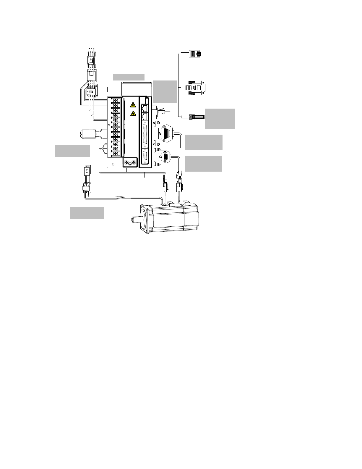
4.1 Peripheral connection
CN2
CN3
When braking resistance or bus
capacitance is insufficient, an
external braking resistor should
connect to P+ terminal and C
terminal
+24V
Electromagnetic contactor
brake control signal.
Open / Close brake power
supply
EMI filter
24V power supply for
brake (only for servo
motor with brake)
System ground
PC communication cable
of servo drive
Servo motor cable
Contactor
Servo motor
3-phae 220V AC / 380V AC
Breaker
CN1 analog
output terminal.
Please see
section 3.6 for
the circuit.
CN2 / CN3 internal
connected in parallel.
Please see section 3.5
for signal definition
Please see section 4
for panel operation
CN4 is connected to the
upper computer.
Please see section 3.4 for
definition and use of CN4
CN5 is connected to servo
motor encoder.
Please see section 3.3 for
definition and use of CN5
Please see section 2.8 for
selection and wiring of
braking resistor
Please see section 3.7
for braking circuit
Power indicator
SINEE EA100
L1C
L2C
L1
L2
L3
P+
D
C
U
V
W
CHARGE
CN1CN2CN3CN4CN5
电源 POWER
电机 MOTOR
制动 BRK
直流母线
Remark:
1) The servo drive is connected to the industry power supply directly, and there is no power isolation like transformer. To prevent electric
shock of servo system, please put a fuse or molded case circuit breaker in the input power supply.
2) Do not install electromagnetic contactor between the drive and the motor, which can damage the drive.
3) Please note the power supply capacity when connect to external control power supply or 24V power supply, especially when the power
supply is connected to several drives or brakes. If power supply capacity is not enough, the output current will also be not enough,
which can lead to the damage of drive or brake. Please note that the brake power supply is 24V DC, whose capacity should be
consistent brake power. Please refer to describe of servo motor for related brake power.
4) Check the servo motor output U, V, W terminal wiring phase. The motor will not run or run out of control and then alarm, or even
damaged by incorrect wiring.
5) When using external resistor, P+ and D terminal should be open, and the external brake resistor should be connected to P+, C terminal.
When using internal brake resistor, P+ and D terminal should be shorted and P+ and C terminal should be open.
6) In 1-phase 220V wiring, the main power supply terminal is L1, L2 terminal, and L3 should be empty.
7) CN2 and CN3 are same defined communication terminals, so that you can use any one of them.
4.2 Main circuit wiring
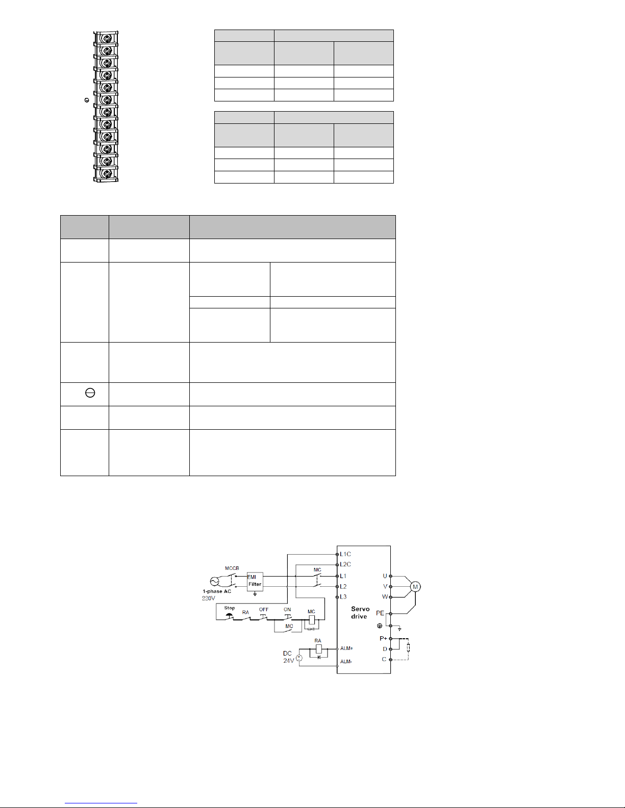
Main circuit (strong electric part) terminals and screw size are shown below.
Page 16
16
L1C
L2C
L1
L2
L3
P+
D
C
U
V
W
SIZE
Main circuit terminal
Screw Size
Tightening
torque
SIZE A
M4
2.5N.m
SIZE B
M4
2.5N.m
SIZE C
M4
2.5N.m
SIZE
PE ground terminal
Screw Size
Tightening
torque
SIZE A
M4
2.5N.m
SIZE B
M4
2.5N.m
SIZE C
M4
2.5N.m
4.2.1 Main circuit (strong electric) terminal Introduction
Table 4-1 servo drive main circuit terminal
Terminals
markings
Terminal name
Terminal Function
L1C, L2C
Control power supply
input terminals
1-phase input which is consistent with the main circuit
power supply voltage level
L1, L2, L3
Main circuit AC
power input terminals
EA100-2R8-2□
EA100-5R5-2□
EA100-7R6-2□
L1, L2 1-phase 220V input
L1, L2, L3 3-phase 220V input
EA100-010-2□
L1, L2, L3 3-phase 220V input
EA100-5R4-3□
EA100-□□□-3□
EA100-026-3□
3-phase 380V input
P+,D,C
External braking
resistor connection
terminals
Default connection between D and P +.
When the braking is insufficient, please keep P +, D
circuit open, and connect an external braking resistor
between the P + and C.
P+,
DC bus terminal
DC bus terminal of servo drive. It can be shared when
multi-parallel.
U,V,W
Servo motor
terminals
Connection terminals of the servo motor and they are
connected to U, V, W of the motor
PE
Ground
One ground terminal for EA100-2R8-2A and
EA100-5R5-2A; Two ground terminals for other power
drives. It is connected to the ground terminal of power
supply and the ground terminal of motor.
4.2.2 Power Wiring
Servo drive power connection is divided into 1-phase and 2-phase. 1-phase only for the drives with output current 7.6A and less than 7.6A
1-phase power supply wiring (rated output current ≤ 7.6A)
Figure 4-1 1-phase power supply wiring diagram
3-phase power supply wiring (all series are applicable)
Page 17
17
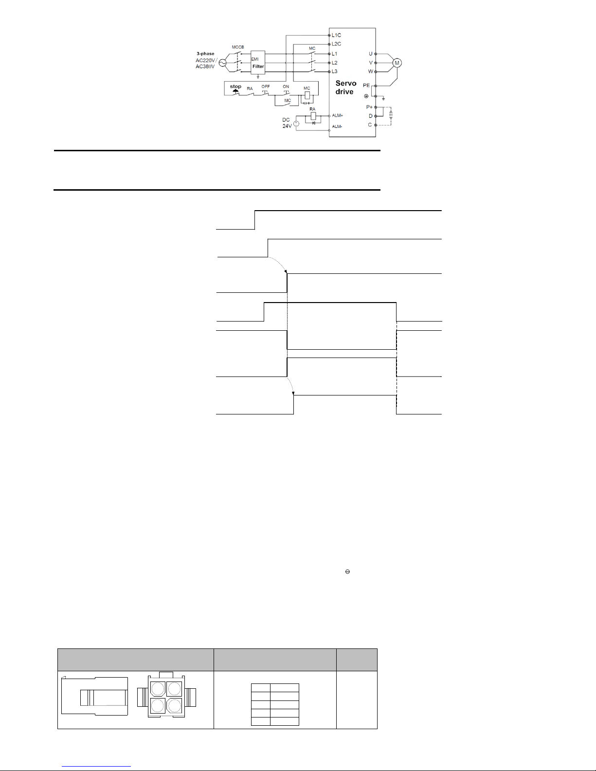
Figure 4-2 3-phase power supply wiring diagram
Remark:
1: If you do not want to cut off the main circuit power supply when a failure occurs, RA relay is
not necessary.
2: L1C, L2C can be connected to P +, - terminals instead of external power supply.
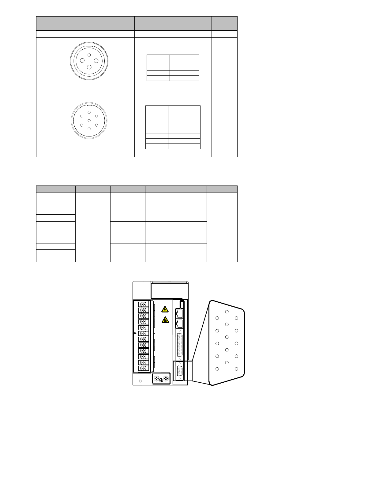
Power on timing
Control circuit power
supply
Mains supply
Servo ready output
(S-RDY)
Servo enable
(S-ON )
Servo motor
excitation
Unpowered
Powered
Unpowered
Powered
Not ready
Ready
Enable invalid
Not receive
instruction
Motor
Unpowered
Motor
powered
Not receive
instruction
Receive instruction
Position / speed /
Torque command
Delay1.5S
Delay as P1-54 set
Servo enable signal
(S-ON signal)
Invalid
Valid
Invalid
Enable invalid
Motor
Unpowered
Enable valid
Figure 4-3 power-on timing chart
Please refer to figure 3-1 and 3-2 for power wiring and wire as followed sequence.
1) Control power circuit L1C, L2C must be powered on before the main circuit or at the same time as the main circuit power supply. If only
the power control circuit is powered on, the servo ready signal (S-RDY) will be invalid.
2) The main circuit power input terminals should be connected to the mains supply by electromagnetic contactor (3-phase: L1, L2, L3, 1
phase: L1, L2).
3) After the main circuit power supply is powered on and a 1.5-second delay, servo ready signal (SRDY) will be valid, then it can accept the
servo enable (S-ON) signal. When detecting the servo enable signal is valid, the motor will be activated, and running. When detecting the
servo enable is invalid or alarmed, output of drive will be off, and the motor is in a free state.
4) When the servo enable and the mains supply are powered on at the same time, the motor will be activated after 1.5 second.
5) Frequently turning on or off of the main circuit power supply may damage the soft start circuit and dynamic braking circuit. The frequency
of tuning on or off should be less than 5 times one hour, and 30 times one day. When the drive or motor is overheating, after the solving
the problem, the main circuit should be powered on again after 30 minutes cooling.
6) The input power cable cannot connect to the output terminals U, V, W, which can damage the servo drive.
7) The braking resistor is absolutely prohibited to be connected to the DC bus P +, terminals, which may lead a fire.
8) After the power is turned off, there may be residual voltage in the servo drive internal capacitance, confirm the CHARGE indicator on the
servo drive panel is off before other operation.
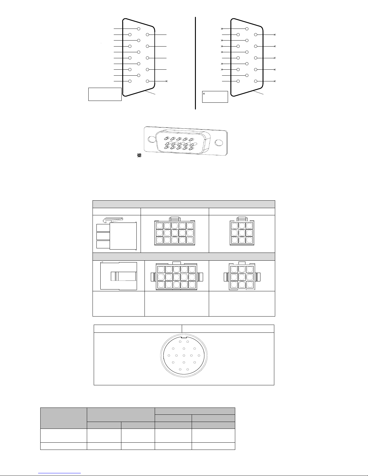
4.2.3 Connector specification of motor power cables
Table 4-2 motor servo motor power cable connection terminals
Connector shape and model
Terminal pinout
Motor
flange size
12
34
Shell model:C4140HM-2X2P
4PIN AMP Plug(without brake)
Pin
Define
1 U 2
V
3 W 4
PE
60
80
86
Page 18
18
Connector shape and model
Terminal pinout
Motor
flange size
Plug model:C4140F-TP-H
1
2
3
4
Model:YD28K4TS
Aviation plug(without brake)
Pin
Define
1
PE
2
U
3
V
4
W
130
1
2
3
4
5
6
7
Model:YD28K7TS
Aviation plug(with brake)
Pin
Define 1 PE
2
24V(brake)
3
0V(brake)
4
not used 5 U
6
V
7
W
130
Note: Due to the product improvement, the aviation plug model may be changed.
4.2.4 Specifications of recommended cable for main circuit connection
Model
L1C,L2C
L1,L2,L3
P+,C
U,V,W
PE
EA100-2R8-2□
0.5mm2
1.0mm2
1.0mm2
1.0mm2
2.5mm
2
above
EA100-5R5-2□
EA100-7R6-2□
2.0mm2
2.0mm2
2.0mm2
EA100-010-2□
EA100-5R4-3□
1.0mm2
1.0mm2
1.0mm2
EA100-8R4-3□
2.0mm2
2.0mm2
2.0mm2
EA100-012-3□
EA100-018-3B
4.0mm2
4.0mm2
4.0mm2
EA100-021-3B
EA100-026-3B
6.0mm2
6.0mm2
6.0mm2
4.3 CN5 encoder signal terminal
CN5 is encoder signal terminal (DB15 socket), its position is shown in Figure 3-4:
1
2
3
4
5
6
7
8
9
10
11
12
13
14
15
SINEE EA100
L1C
L2C
L1
L2
L3
P+
D
C
U
V
W
CHARGE
电源 POWER
直流母线
制动 BRK
电机 MOTOR
CN1CN2CN3CN4CN5
Figure 4-4 CN5 terminal positions
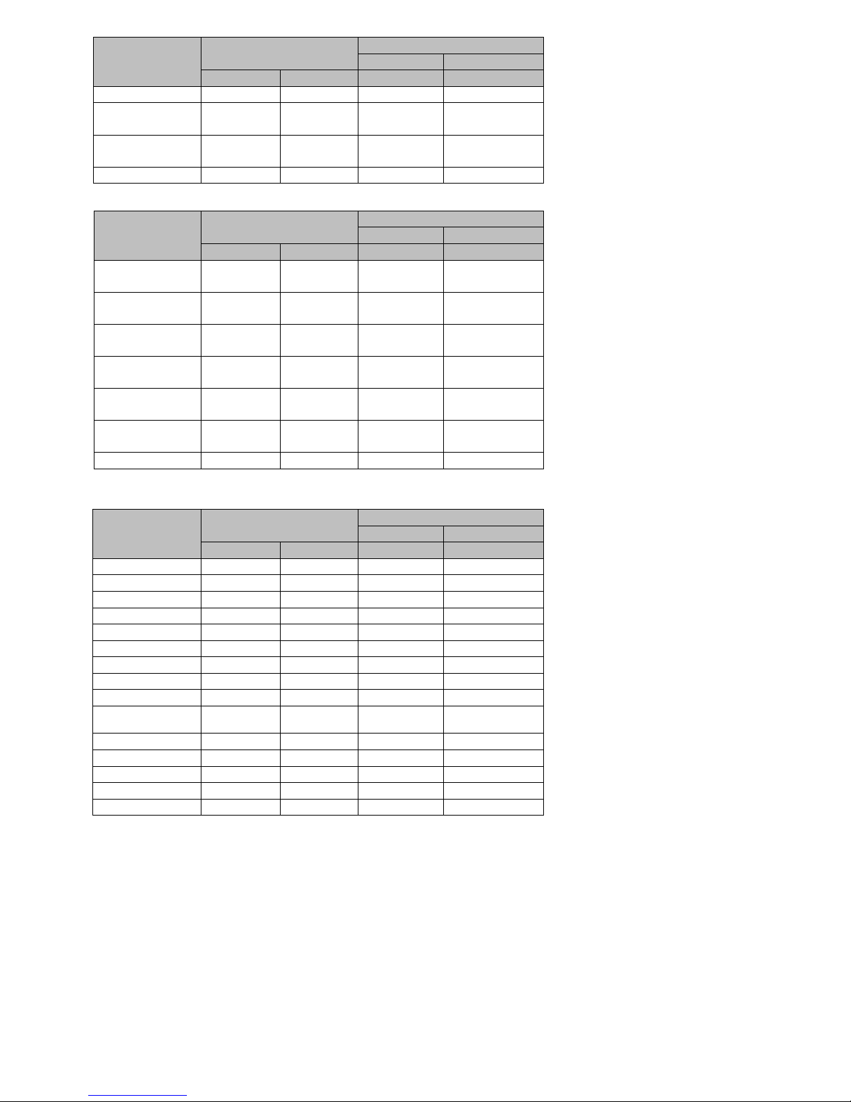
4.3.1 Encoder terminal definition drive-side
Page 19
19
5
10
4
9
3
8
2
7
1
15
14
13
12
11
6
Encoder B+ signal
Encoder B- signal
Encoder A+ signal
Encoder A- signal
Shielded layer
connect to PE
Encoder Z- signal
Encoder U- signal
Encoder V- signal
Encoder W- signal
Encoder power
supply 5V
Encoder Z+ signal
Encoder U+ signal
Encoder V+ signal
Encoder W+ signal
GND
5
10
4
9
3
8
2
7
1
15
14
13
12
11
6
Shielded layer
connect to PE
Encoder power
supply 5V
SD+
SD-
GND
CN5 2500ppr incremental encoder terminal definition
CN5 17-bit encoder terminal definition
It indicates that the
terminal Is Left,
and do not connect
Note: When connected to
the wire-saving encoder, U
+ / U-, V + / V-, W + / W-,
Need not to be connected.
Figure 4-5 CN5 terminal pinout
2KΩ
100Ω
100Ω
1
33
34
上位机装置
100Ω
100Ω
31
32
14
16
PULSE+
PULSE-
SIGN+
SIGN-
GND
PE
GND
GND
伺服驱动器
普通脉冲位置指令
最小脉冲宽度1us
最大输入频率为500kpps
PULHIP
PULHIS
1
6
11
5
10
15
Figure 4-6 CN 5 terminal welding pinout
4.3.2 Encoder terminal definition of servo motor side
There are two shapes encoder terminal in the servo motor side.
AMP plug,for motor with 60, 80 flange, the pin defined in Table 4-3a, 3b, 3c
Plugs in motor side
Shape
2500ppr incremental encoder
17 bit encoder
4 532
1
9 107
6
14 151312
11
8
Motor side
321
64
987
5
Motor side
Encoder cable connector
15
610
11
15
234
9 7
12
1314
8
123
6 4
7
89
5
Shell model:
C4140-HM-3*5P
Plug model:
C4140F-TP-L
Shell model:
C4140-HM-3*3P
Plug model:
C4140F-TP-L
Aviation plug: for motor with 110 flange and above, the pin defined in Table 4-3a, 3b, 3c
2500ppr incremental encoder
17 bit encoder
2
5
14
13
15
11
10
6
3
1
Terminal type:YD28K15TS
Note: Due to the product improvement, the aviation plug model may be changed.
Table 4-3a 17-bit incremental encoder cable connection
Function
Description
Drive side DB15
Servo motor side
AMP plug
Aviation plug
Signal name
Pin
Pin
Pin
Encoder power
supply
+5V 5 1
2
Encoder power
GND
10 2 3
Page 20
20
Function
Description
Drive side DB15
Servo motor side
AMP plug
Aviation plug
Signal name
Pin
Pin
Pin
supply ground
Positive terminal
of serial signal
SD+ 1 5
4
Negative terminal
of serial signal
SD- 3 6
7
Shield layer PE
PE
Shell 9 1
Table 4-3b 17-bit absolute encoder cable connection
Function
Description
Drive side DB15
Servo motor side
AMP plug
Aviation plug
Signal name
Pin
Pin
Pin
Encoder power
supply
+5V 5 1
2
Encoder power
supply ground
GND
10 2 3
Positive terminal
of serial signal
SD+ 1 5
4
Negative terminal
of serial signal
SD- 3 6
7
Positive terminal
of external battery
VB+ 7
14
Negative terminal
of external battery
VB- 8
15
Shield layer PE
PE
Shell 9 1
Table 4-3c 2500ppr non-wire-saving encoder cable connection
Function
Description
Drive side DB15
Servo motor side
AMP plug
Aviation plug
Signal name
Pin
Pin
Pin
Encoder signal Z +
Z+ 1 7
6
Encoder signal U +
U+ 2 6
10
Encoder signal V +
V+ 3 10
11
Encoder signal W +
W+ 4 11
12
Encoder supply 5V
+5V 5 2
2
Encoder signal Z-
Z- 6 5
9
Encoder signal U-
U- 7 8
13
Encoder signal V-
V- 8 12
14
Encoder signal W-
W- 9 15
15
Encoder power
supply ground
GND
10 3 3
Encoder signal B +
B+
11 4 5
Encoder signal B-
B-
12
14
8
Encoder signal A +
A+
13 9 4
Encoder signal A-
A-
14
13
7
Shielding layer PE
PE
Shell 1 1
Remark for servo wiring:
1) Make sure the drive and the motor shielded layer are grounded; otherwise it will cause the drive error.
2) Do not confuse GND and PE.
3) Be sure that the differential signal can match the two cables of a twisted pair. For example, A + and A- is a set of differential signal, you
should use a twisted pair.
4) Encoder cable routing must be separated from the power cable routing by at least 30cm or more.
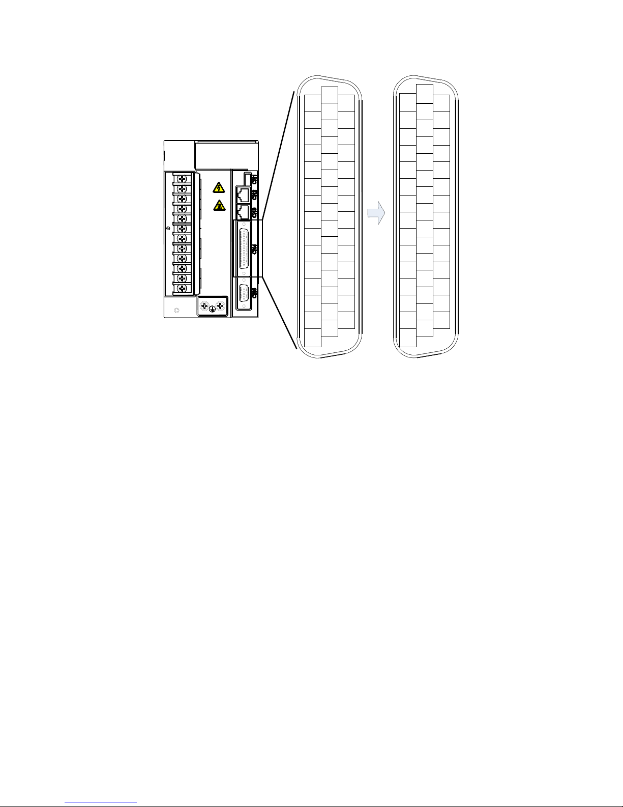
4.4 CN4 Control signal terminal
Using the DB44 socket, CN4 signal terminal provides signals for communication with upper computer.
Signals include:
8 programmable digital inputs
4 programmable digital differential output
Page 21
21
2 analog inputs
command pulse input
ABZ encoder signal output
SINEE EA100
L1C
L2C
L1
L2
L3
P+
D
C
U
V
W
CHARGE
15 14 13 12 11 10 9 8 7 6 5 4 3 2 1
30 29 28 27 26 25 24 22 21 20 19 18 17
44 43 42 41 40 39 38 37 36 35 34 33 32 31
1623
AI1
GND
PA- PB+ PZ+
DO4- DO3 DO1
COM
+5V DI1 DI3 DI5 DI7
AI2
GND
PA+
PB- PZ-
+24V DO4
COM COM+
DI2 DI4 DI6 DI8
GND GND GND GND +24V
DO3- DO2- DO1-
COM
OCZ
DO2
PULIHP
PULIHS
SIGN+
PULSE+
SIGN-
PULSE-
电源 POWER 直流母线 制动 BRK 电机 MOTOR
Figure 4-7 Drive control circuit terminal position and pin assignment
Page 22
22
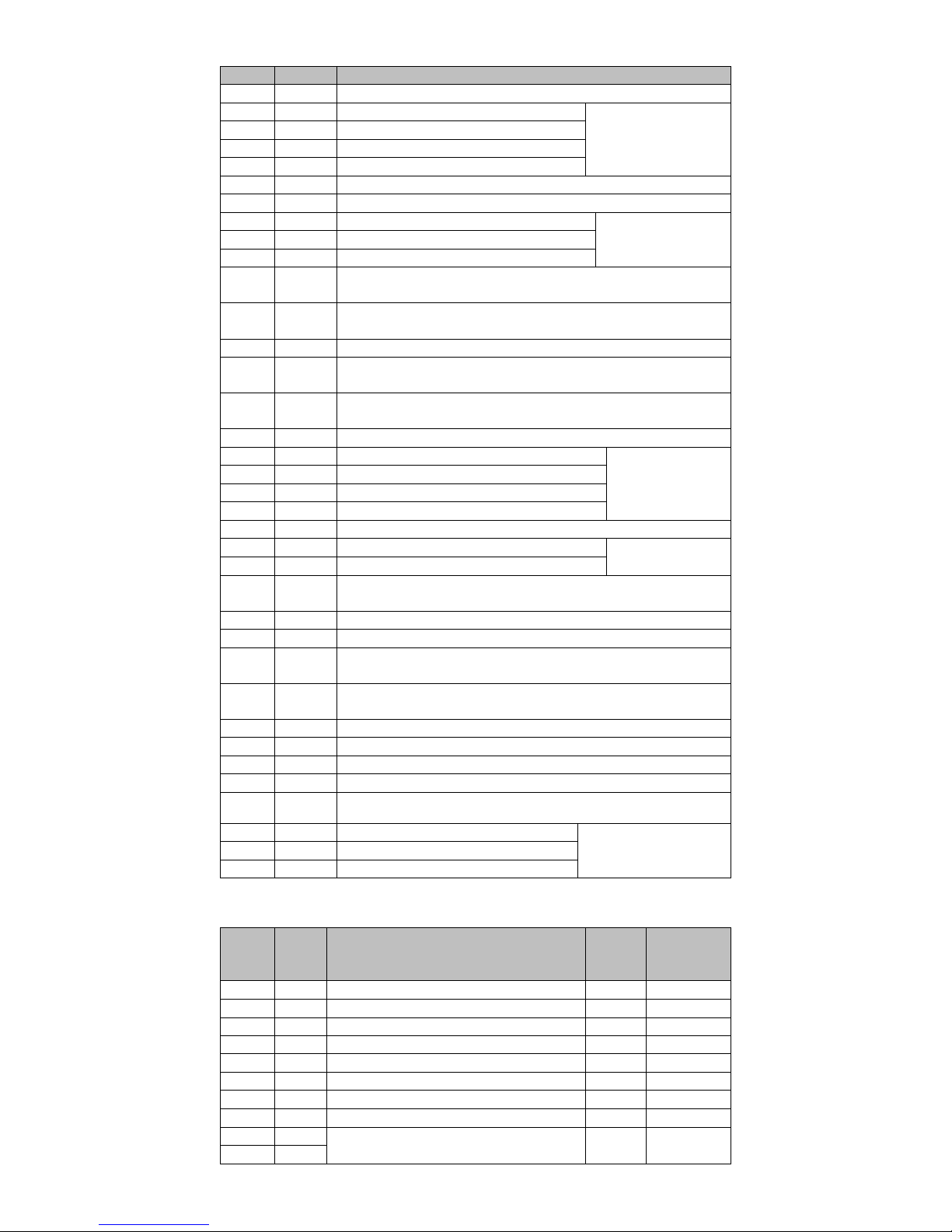
4.4.1 Control signal terminal pin distribution
Signal
Pin
Function description
PULHIP
1
The positive terminal of command pulse when using 24V power supply
DI7
2
Digital input, the default function number is 7
See section 3.4.2 and
3.4.3
DI5
3
Digital input, the default function number is 5
DI3
4
Digital input, the default function number is 3
DI1
5
Digital input, the default function number is 1
+5V
6
+ 5V power supply, maximum output current 50mA.
COM
7/22/36
Power supply ground (+ 24V)
DO1
8
Digital output, the default function number is 1
See section 3.4.2 and
3.4.4
DO3
9
Digital output, the default function number is 8
DO4-
10
DO4 digital output COM terminal
PZ+
11
Z pulse positive frequency dividing output, the maximum current is
20mA.
PB+
12
B pulse positive frequency dividing output, the maximum current is
20mA.
PA-
13
A pulse negative frequency dividing output
GND
14/29/41/4
2/43/44
Analog input signal ground
AI1
15
Analog input, input impedance: 10kΩ, the maximum input voltage ±
12V.
PULHIS
16
The positive terminal of command pulse when using 24V power supply
DI8
17
Digital input, the default function number is 8
See section 3.4.2 and
3.4.3
DI6
18
Digital input, the default function number is 6
DI4
19
Digital input, the default function number is 4
DI2
20
Digital input, the default function number is 2
COM+
21
Digital input common positive terminal
DO2
23
Digital output, the default function number is 2
See section 3.4.2 and
3.4.4
DO4
24
Digital output, the default function number is 12
+24V
25/40
Internal 24V power supply, voltage range of + 20V ~ 26V.
The maximum output current is200mA.
PZ-
26
Encoder Z pulse negative output
PB-
27
Encoder B pulse negative output
PA+
28
Encoder A pulse positive output.
The maximum current is 20mA.
AI2
30
Analog input. The input impedance is 10kΩ,
The maximum allowable input voltage is ± 12V.
SIGN+
31
Position direction command +
SIGN-
32
Position direction command -
PULSE+
33
Position pulse command +
PULSE-
34
Position pulse command -
OCZ
35
Encoder Z pulse open collector output.
The maximum allowable input current is 40mA.
DO1-
37
COM digital output terminal of DO1
See section 3.4.2 and 3.4.4
DO2-
38
COM digital output terminal of DO2
DO3-
39
COM digital output terminal of DO2
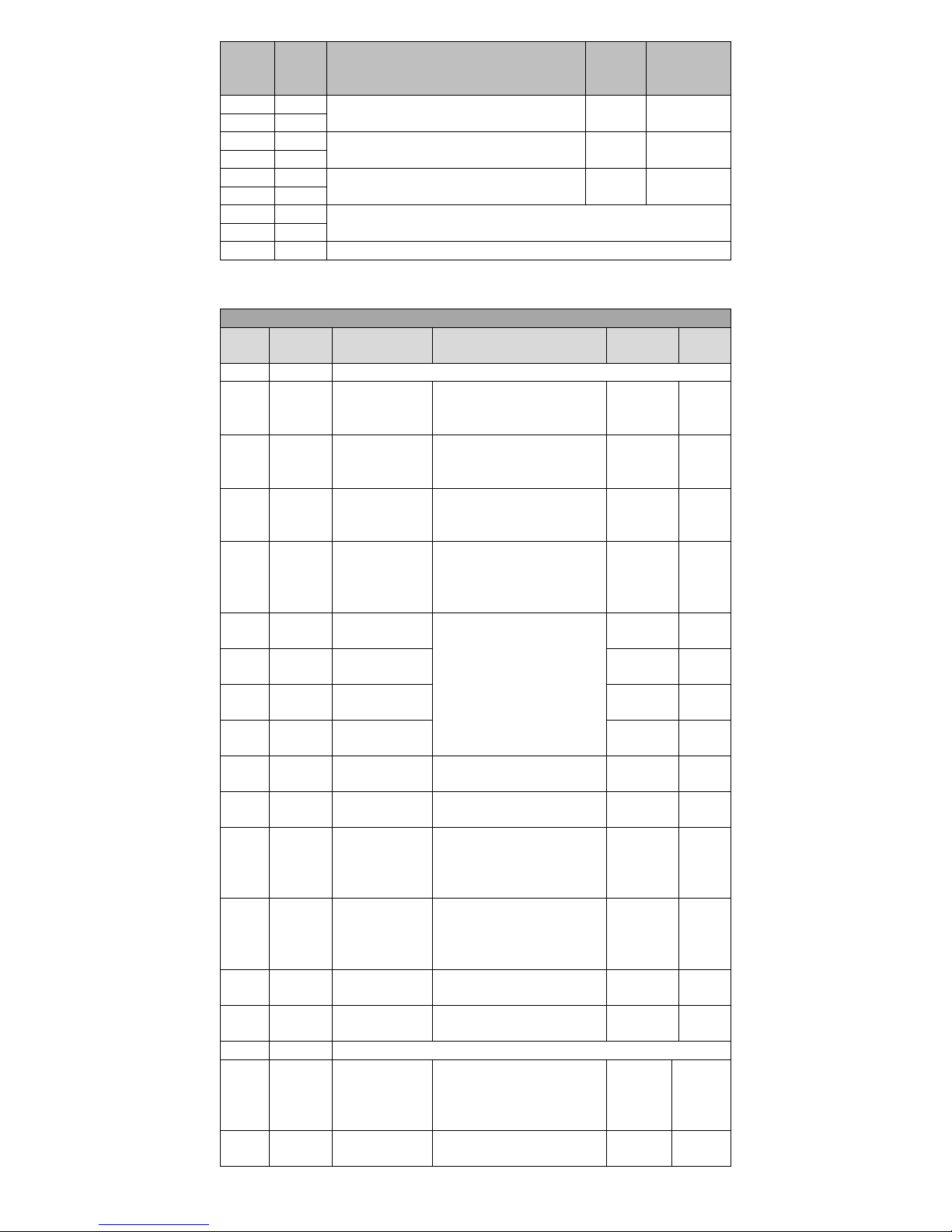
4.4.2 Digital Input \ Output Terminal Description
Signal
Pin
Default function
Default
function
number
Corresponding
function code
DI1
5
Servo motor power on enable
1
P6-02
DI2
20
Alarm fault reset
2
P6-03
DI3
4
Position control pulse deviation counter clear
3
P6-04
DI4
19
Speed instruction direction selection
4
P6-05
DI5
3
Internal instruction bit0
5
P6-06
DI6
18
Internal instruction bit1
6
P6-07
DI7
2
Internal instruction bit2
7
P6-08
DI8
17
Internal instruction bit3
8
P6-09
DO1
8
Servo ready output signal
The maximum allowable output current 40mA
1
P6-13
DO1-
37
Page 23
23
Signal
Pin
Default function
Default
function
number
Corresponding
function code
DO2
23
Brake output signal
The maximum allowable output current 40mA
2
P6-14
DO2-
38
DO3
9
Rotation of the motor output signal
The maximum allowable output current 40mA
8
P6-15
DO3-
39
DO4
24
Output signal stops servomotor
The maximum allowable output current 40mA
12
P6-16
DO4-
10
+24V
25/40
Internal 24V supply voltage range + 22V ~ 26V, 200mA maximum output
current
COM
7/22/36
COM+
21
Digital input common positive terminal(12V~24V)
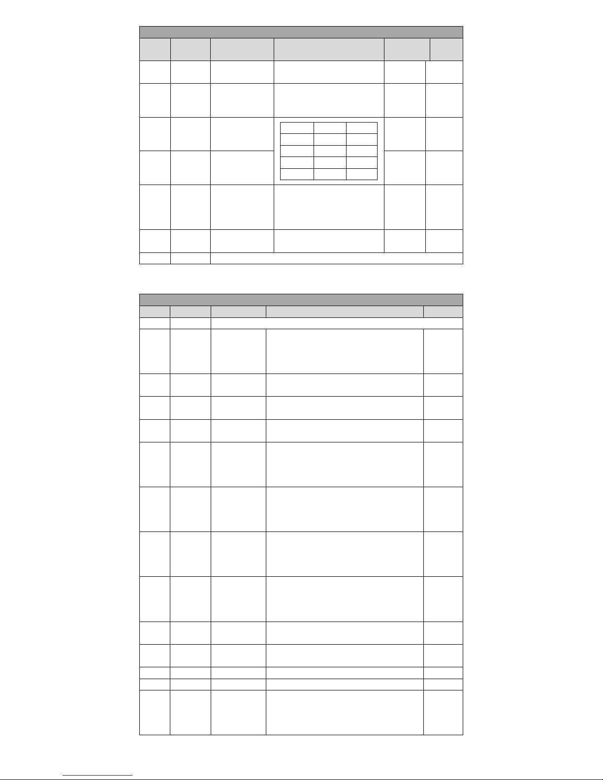
4.4.3 Digital input (DI) function definition table
Input Signal Function Description
Set
value
Name
Function
Describe
Trigger
mode
Running
mode
0
Disabled
Terminal invalid
1
S-ON
Servo enable
ON- Servo motor power enable
OFF- Servo motor cancel
enabled
Level
triggered
P S T
2
ALM-RST
Alarm and fault
reset
ON- If the abnormal condition
have been solved, resettable
fault can be reset.
Edge
triggered
P S T
3
P-CLR
Position control
pulse deviation
counter clear
See P1-34 for definition of
trigger
Edge / level
triggered
P
4
DIR-SEL
Speed command
direction
selection
ON- Instruction in the opposite
direction
OFF- Default command
direction
Level
triggered
S
5
CMD0
Internal
instruction bit0
When works in position control
mode, it is location
multi-segment switching
function signal;
When works in speed control
mode, it is speed multi-segment
switching function signal;
Level
triggered
P S
6
CMD1
Internal
instruction bit1
Level
triggered
P S
7
CMD2
Internal
instruction bit2
Level
triggered
P S
8
CMD3
Internal
instruction bit3
Level
triggered
P S
9
CTRG
Internal
instruction trigger
Multi- segment position trigger
condition
Edge
triggered
P
10
MSEL
Control mode
switching
Used for mixed control mode
switch
Level
triggered
P S T
11
ZCLAMP
Analog speed
command zero
fixed enable
ON- Zero fixed function
enabled
OFF- Zero fixed function
disenabled
Level
triggered
S
12
INHIBIT
Pulse inhibit
ON- Prohibit command pulse
input
OFF- Allow command pulse
input
Level
triggered
P
13
P-OT
Forward driving
inhibit
OFF- Prohibit forward drive
ON- Allow forward drive
Level
triggered
P S T
14
N-OT
Reverse driving
inhibit
OFF- Prohibit Reverse driving
ON- Allow reverse drive
Level
triggered
P S T
15,16
Not used
17
JOGCMD+
Forward Jog
ON- Input in accordance with
the given instruction
OFF- Stop input running
instruction
Level
triggered
S
18
JOGCMD-
Reverse Jog
ON- Input in accordance with
the given instruction
Level
triggered
S
Page 24
24
Input Signal Function Description
Set
value
Name
Function
Describe
Trigger
mode
Running
mode
OFF- Stop input running
instruction
19
TDIR-SEL
Torque command
direction
selection
OFF-Default function
ON- Instruction Reverse
Level
triggered
T
20
GNUM0
Electronic gear
ratio numerator
selection 0
GNUM1
GNM0
code
0 0 P1-27
0 1 P1-29 1 0
P1-30 1 1
P1-31
Level
triggered
P
21
GNUM1
Electronic gear
ratio numerator
select 1
Level
triggered
P
22
ORGP
External detector
input
Up eage: external detector
valid
Down eage:external detector
invalid
Edge
triggered
P S T
23
SHOM
Origin return
function
ON:Origin return function
enable
Level
triggered
P S T
Not used
4.4.4 Digital Output (DO) function definition table
Input Signal Function Description
Set value
Set value
Set value
Set value
0
Disable
Terminal is invalid
1
S-RDY+-
Servo ready
Valid - servo ready,can receive S-ON
instruction
Invalid - Servo not ready,cannot receive
S-ON instruction
P S T
2
BK+-
Brake control
Valid - Release holding brake
Invalid - Closed holding brake
P S T
3
TGON+-
Motor rotation
Valid - The motor is rotating
Invalid - The motor stop rotating
P S T
4
ZER0+-
Motor zero
speed
Valid - Motor speed is zero
Invalid - Motor speed is not zero
P S T
5
V-CLS+-
Speed
approaching
Valid : when works in speed control, the
absolute value of the difference between the
actual motor speed and the speed command is
less than the value as P1-42 set.
S
6
V-CMP+-
Speed arrival
Valid:when works in speed control mode, the
absolute value of the difference between the
actual motor speed and the speed command is
less than the value as P1-43 set.
S
7
PNEAR+-
Position
approaching
Valid:when works in position control mode,
the position deviation pulse number is less
than positioned close approaching width as
P1-32 set.
P
8
COIN+-
Position arrival
Valid:when works in position control mode,
the position deviation pulse number is less
than positioned close approaching width as
P1-33 set.
P
9
C-LT+-
Torque limit
signal
Valid - Motor torque is limited
Invalid - Motor torque is not limited
P S
10
V-LT+-
Speed limit
signal
Valid - Motor speed is limited
Invalid - Motor speed is not limited
T
11
WARN+-
Warning output
Valid:Warning things occur
P S T
12
ALM+-
Fault output
Valid:Fault event occur
P S T
13
Tcmp+-
Torque arrival
signal
Valid:Motor output torque reaches the set
value
Invalid:Motor output torque does not reach
the set value
T
Page 25
25
Input Signal Function Description
Set value
Set value
Set value
Set value
14
Home+-
Origin return
signal
Valid:Origin return accomplished
Invalid:Origin return not accomplished
P S T
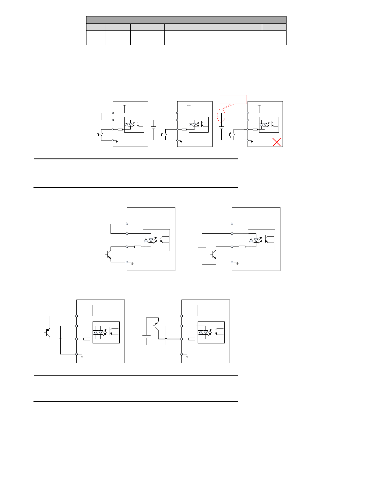
4.4.5 Digital input wiring
The digital input terminals (DI) of EA100 servo drive adopt full bridge rectifier circuit. The current through the terminal can be positive (NPN
mode), or negative (PNP mode). So the external connections of DOI ~ DI8 terminals can be very flexible.
Here is an example of DI1. The interface circuitry of DI1 ~ DI8 is the same.
1) When host device is relay output:
4.7K
+24V
+ 24V
power supply
COM+
DI1
Relay
COM
Servo internal 24V power supply
4.7K
+24V
COM+
DI1
Relay
COM
Servo internal 24V power supply
DC24V
4.7K
+24V
COM+
DI1
COM
Servo drive Servo drive
Do not use a separate
power supply
25
21
5
7
25
21
5
7
25
21
5
7
Relay
DC24V
+ 24V
power supply
+ 24V
power supply
Figure 4-8 Digital input terminal when host device is relay output
Remark:Some of manual defaults are as followed:
COM: 7pin,users can also use 22/36 pin
GND: 14pin,users can also use 29/41/42/43/44 pin
Servo internal +24V: 25pin,users can also use 40pin
2) When host device is NPN open collector output
4.7K
+24V
+24V Power
supply
COM+
DI1
COM
Servo internal 24V power supply
Servo drive
NPN input
NPN
4.7K
+24V
+24V Power
supply
COM+
DI1
COM
Servo internal 24V power supply
Servo drive
NPN input
NPN
DC24V
25
21
5
7
25
21
5
7
Figure 4-9 (a) Digital input terminal when host device is NPN open collector output
3)When host device is PNP open collector output:
4.7K
+24V
+24V Power supply
COM+
DI1
COM
Servo internal 24V power supply
Servo drive
PNP input
PNP
4.7K
+24V
+24V Power
supply
COM+
DI1
COM
Servo internal 24V power supply
Servo drive
PNP input
PNP
DC24V
25
21
5
7
25
21
5
7
Figure 4-9(b) Digital input terminal when host device is PNP open collector output
Remark:
1. Be sure that the 24V and COM + terminals are not connected when using an external power
supply.
2. PNP and NPN input cannot be used mixedly
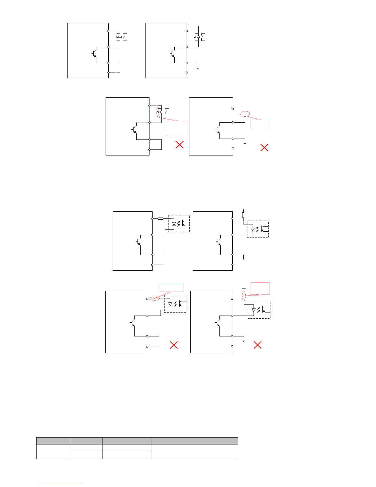
4.4.6 Digital output wiring
Here is an example of DO1. The interface circuitry of DO1 ~ DO4 is the same.
1) When host device is relay input:
Page 26
26
DC5V~24V
NPN
relay
Servo drive
DO1
DO1-
8
37
When using internal power supply
25
+24V
COM
22
NPN
relay
Servo drive
DO1
DO1-
8
37
25
22
Figure 4-10(a) Correct digital input wiring when host device is relay output
NPN
DC5V~24V
DO1
DO1-
Relay Not
Accessed
8
37
25
22
NPN
Relay
Servo drive
DO1
DO1-
8
37
25
+24V
COM
22
Wrong polarity
of freewheeling
diode
Servo drive
Figure 4-10(b) incorrect digital input wiring when host device is relay output
Remark:
When the host device is relay input, make sure to access the freewheeling diode, or it may damage the DO port.
2) When the host device is optocoupler input
NPN
DC5V~24V
Servo drive
DO1
DO1-
8
37
NPN
Servo srive
DO1
DO1-
8
37
Using internal power supply Using external power supply
25
+24V
COM
22
25
COM
22
External power
supply ground
Figure 4-11(a) correct digital input wiring when the host device is optocoupler input
NPN
DC5V~24V
Servo drive
DO1
DO1-
8
37
NPN
DO1
DO1-
8
37
When using internal power supply When using external power supply
25
+24V
COM
22
25
COM
22
Not connected with
current limit resistor
Not connected
with current
limit resistor
External power
supply ground
Servo drive
Figure 4-11(b) incorrect digital input wiring when the host device is optocoupler input
Remark:
The maximum allowable voltage, current capacity of servo drive internal optocoupler output circuit is as followed:
Voltage:DC30V(maximum)
Current: DC 50mA (maximum)
If driving the inductive loads (relay, contactor), a surge voltage absorption circuit should be added; such as RC absorption circuit (the
leakage current should be less than the holding current of contactor or relay) varistor, or freewheeling diode (for DC circuit, check the
polarity during installation). The element of snubber circuit should be closed to the relay or contactor.
4.4.7 CN4 analog input terminal wiring
Table 4-4 analog input terminal description
Signal name
Function
Pin
Function describe
Analog
AI1
15
Voltage analog input
AI2
30
Page 27
27
GND
29
Analog input ground
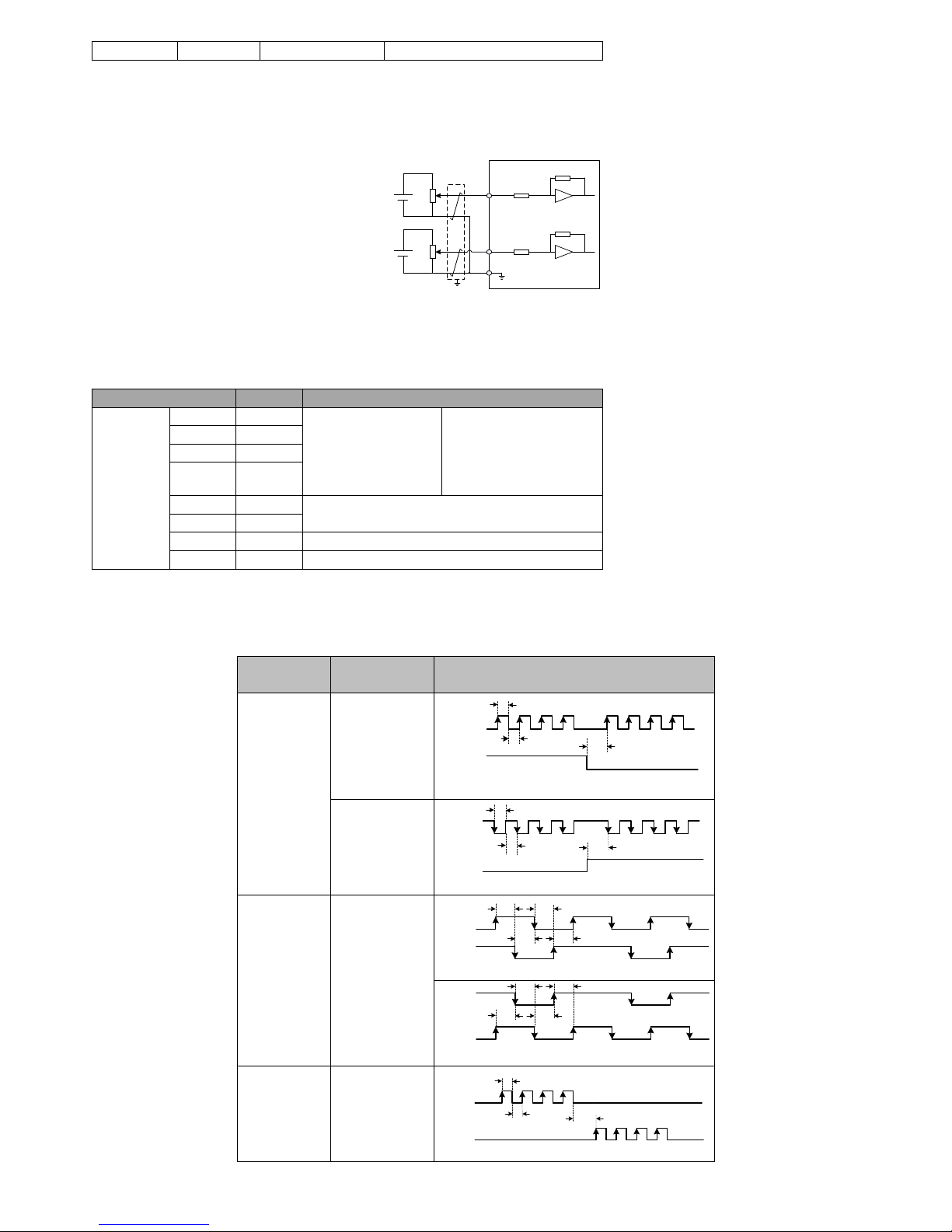
AI1, AI2 generally used for speed and torque analog signal input。
Input voltage range:-10V~+10V, resolution 12 bit;
Maximum allowable voltage:±12V;
Input impedance:10K;
-10~+10V
AI1
-10~+10V
AI2
About 9K
About 9K
Servo motor
GND
15
30
29
Figure 4-12 AI1, AI2 terminal wiring diagram
4.4.8 CN4 position command input signal
Describe for position command pulse input signal, the instruction symbol input signal terminal of CN4 are as followed.
Table 4-4 position pulse input signal specifications
Signal name
Pin
Function
Position
instruction
PULSE+
33
Pulse command input:
Differential Input
Open collector input
Input pulse shape:
Direction + pulse
A, B phase orthogonal
pulse
CW/CCW pulse
PULSE-
34
SIGN+
31
SIGN-
32
PULHIP
1
External power input interface of command pulse
PULHIS
16
GND
41
5V power supply ground
COM
36
24V power supply ground
Pulse command can be input by open collector input or differential input. The maximum differentia input pulse wave is 500Kpps, maximum
open collector input pulse wave is 200Kpps.
Different forms of command input pulse has different timing parameters,see section table 3-5 table 3-6 for details:
Table 4-5 different command pulse timing table
Pulse instruction
form
Logic state
Pulse waveform
Direction+
pulse
P1-02=0
Positive logic
PULSE
SIGN
T3
T2
Forward
Reversal
T1
P1-02=1
Negative logic
PULSE
SIGN
T3
T2
Forward
Reversal
T1
Two-phase
orthogonal
pulses (4times)
P1-02=2
Positive logic
PULSE
SIGN
T4 T4
Forward
T4
T4
Reversal
PULSE
SIGN
T4
T4
T4
T4
CCW/CW pulse
P1-02=4
Positive logic
PULSE
SIGN
T3
T1
T2
Forward Reversal
Page 28
28
Pulse instruction
form
Logic state
Pulse waveform
P1-02=5
Negative logic
Forward
Reversal
PULSE
SIGN
T3
T1
T2
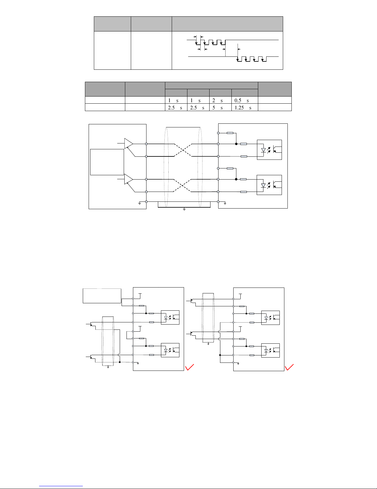
Table 4-6 Pulse input time parameter
Pulse mode
Maximum
input frequency
The minimum allowable width
Voltage
T1
T2
T3
T4
Differential
500Kpps
5V
Open collector
200Kpps
24V(MAX)
4.4.8.1 Position instruction pulse differential input mode
EA100
2KΩ
100Ω
100Ω
1
33
34
Upper computer
100Ω
100Ω
31
32
41
16
GND
PULSE+
PULSE-
SIGN+
SIGN-
The minimum
position instruction
pulse width is 1us
The maximum input
frequency is 500kpps
PE
GND
2KΩ
Figure 4-13 Position instruction pulse differential input mode wiring
Please ensure "2.8V≤ (H level -L level) ≤3.7V", otherwise the servo drive input pulse will be unstable. It will result in the following
situations:
Missing pulse when enter instruction pulse.
The instruction is opposite when enter instruction direction
4.4.8.2 Position instruction pulse differential input mode Instruction direction
When using the servo internal 24V power supply
2KΩ
100Ω
100Ω
1
33
34
100Ω
100Ω
31
32
36
16
PULSE-
SIGN-
COM
+24V
+24V
PULHIP
PULHIS
+24V
power
supply
+24V
power
supply
2KΩ
100Ω
100Ω
1
33
34
100Ω
100Ω
31
32
36
16
PULSE-
SIGN-
COM
+24V
+24V
PULHIP
PULHIS
+24V
power
supply
+24V
power
supply
25
25
PULSE+
SIGN+
Servo drive
Servo drive
PULSE+
PE
PE
NPN
PNP
Open collector pulse position
instruction. The maximum input
frequency is 200kpps. The
minimum pulse width is 2.5us
25
25
2KΩ
2KΩ
Figure 4-14 open collector pulse input command wiring diagram (using the servo internal 24V)
When using the servo external 24V power supply
Page 29
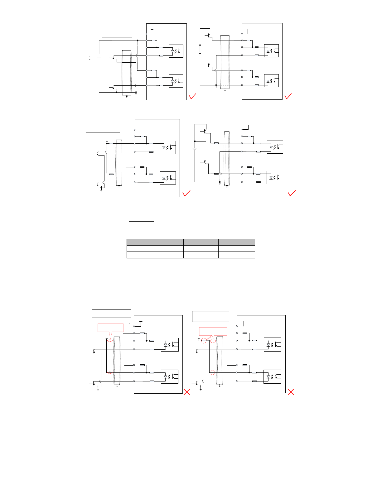
29
2KΩ
100Ω
100Ω
1
33
34
100Ω
100Ω
31
32
16
PULSE+
SIGN-
COM
+24V
PULHIP
PULHIS
+24V
25
SIGN+
PULSE-
2KΩ
100Ω
100Ω
1
33
34
100Ω
100Ω
31
32
16
PULSE-
SIGN-
+24V
PULHIP
PULHIS
25
+24V
PULSE+
SIGN+
Servo drive Servo drive
PE
PE
NPN
PNP
Open collector pulse position
instruction. The maximum input
frequency is 200kpps. The
minimum pulse width is 2.5us
COM
external
external
2KΩ
2KΩ
Figure 4-15 (a) open collector pulse input command wiring diagram (using external power supply and internal limiting resistor)
2KΩ
100Ω
100Ω
1
33
34
100Ω
100Ω
31
32
16
PULSE+
SIGN-
COM
+24V
PULHIP
PULHIS
25
SIGN+
PULSE-
2KΩ
100Ω
100Ω
1
33
34
100Ω
100Ω
31
32
16
PULSE-
SIGN-
+24V
PULHIP
PULHIS
25
PULSE+
SIGN+
Servo drive Servo drive
PE
PE
NPN
Open collector pulse position
instruction. The maximum input
frequency is 200kpps. The
minimum pulse width is 2.5us
COM
VCC
R1
R1
VCC
R1
R1
PNP
2KΩ 2KΩ
Figure 4-15 (b) open collector pulse input command wiring diagram (using external power supply and external limiting resistor)
Selection of limit resistor R1is as followed:
The selection of resistor R1 is satisfied :
1.5
10
1 200
CC
V
mA
R
Recommended resistance for R1:
VCC voltage
R1 resistance
R1 power
24V
2.0K
0.5W
12V
0.8K
0.5W
Remark:
1) Make sure a pair of differential signals is connected with a twisted two cables
2) Encoder cable routing must be separated from the power cable routing by at least 30cm or more.
3) The pulse input interface is not shielded input interface. In order to reduce noise, we recommend the ground output signal of the upper
computer the ground output signal of the servo drive should be connected together.
Examples of typical wrong wiring
2KΩ
100Ω
100Ω
1
33
34
100Ω
100Ω
31
32
16
PULSE+
SIGN-
COM
+24V
PULHIP
PULHIS
25
SIGN+
PULSE-
Servo drive
PE
VCC
Missed limiting
resistor
2KΩ
100Ω
100Ω
1
33
34
100Ω
100Ω
31
32
16
PULSE+
SIGN-
COM
+24V
PULHIP
PULHIS
25
SIGN+
PULSE-
Servo drive
PE
VCC
Not using separate
current limiting resistor
Error 1: Missed limiting resistor,
the port will damage
Error 2: shared limiting resistor
for Multiple port, resulting in
pulse reception error
2KΩ
2KΩ
Page 30
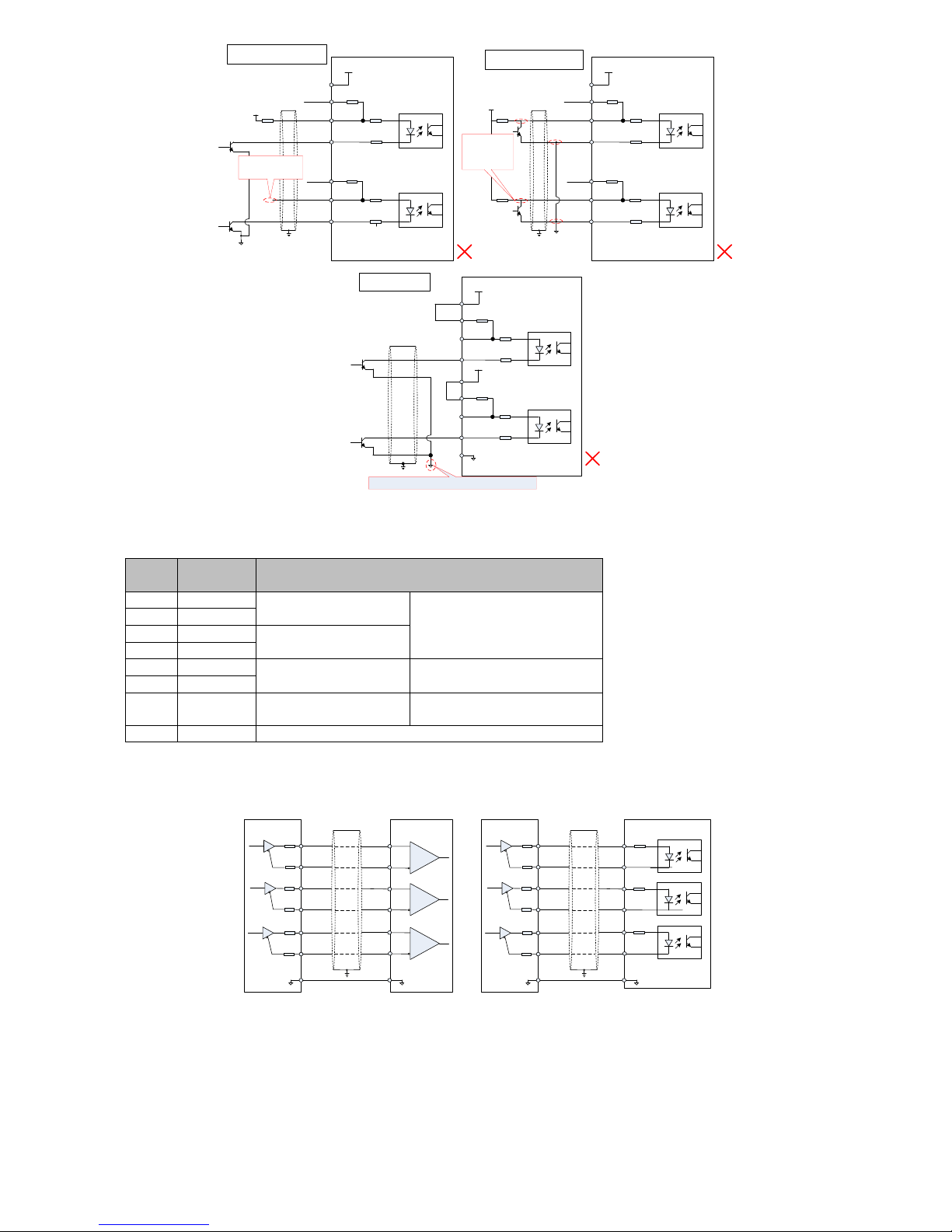
30
2KΩ
100Ω
100Ω
1
33
34
100Ω
100Ω
31
32
16
PULSE+
SIGN-
COM
+24V
PULHIP
PULHIS
25
SIGN+
PULSE-
Servo drive
PE
Error 3: SIGN port missed, So that
the two ports can not receive pulse
VCC
R1
SIGN signal
missing
2KΩ
100Ω
100Ω
1
33
34
100Ω
100Ω
31
32
16
PULSE+
SIGN-
+24V
PULHIP
PULHIS
25
SIGN+
PULSE-
Servo drive
PE
Error 4: wrong port, so that the port
may be burned
VCC
The collector
signal dose not
access to the
specified port
COM
2KΩ 2KΩ
2KΩ
100Ω
100Ω
1
33
34
100Ω
100Ω
31
32
36
16
PULSE-
SIGN-
COM
+24V
+24V
PULHIP
PULHIS
+24V电源
+24V电源
25
PULSE+
SIGN+
36 pin is not connected. And unable to form a closed loop
Servo drive
PE
25
2KΩ
Error 5: Signal loop is not
formed
Figure 4-16 5 typical wiring errors
4.4.9 CN4 encoder output frequency division circuit
Table 3-8 Encoder frequency division output signal description
Signal
name
Pin
Function
PA+
28
A Phase frequency division
output signal
A,B orthogonal frequency pulse
output signal
PA-
13
PB+
12
B Phase frequency division
output signal
PB-
27
PZ+
11
Z Phase frequency division
output signal
Origin pulse output signal
PZ-
26
OCZ
35
Z Phase frequency division
output signal
Origin pulse open collector output
signal
GND
14/42/43/44
Origin pulse open collector output signal ground
Encoder frequency division circuit output differential signals by a differential drive. Generally, it will provide a feedback signal when the drive
and the host device constituting the position control system. In the upper computer device, please use a differential or optocoupler receive as
circuit receive. The maximum output current is 20mA.
28
PA-
GND
PA+
Differential receive
PB+
PB-
PZ+
PZ-
Upper
computer
13
12
27
11
26
14
GND
28
PA-
GND
PA+
Optocoupler receive
PB+
PB-
PZ+
PZ-
Upper
computer
13
12
27
11
26
14
GND
PE
PE
Servo drive
Servo drive
Figure 4-17 frequency division output wiring diagram
Encoder Z-phase frequency division circuit can provide a feedback signal by open collector output signal when the drive and the host device
constituting the position control system. In the upper computer device, please use a relay or optocoupler receive as circuit receive. The
maximum output current is 40mA.
Page 31
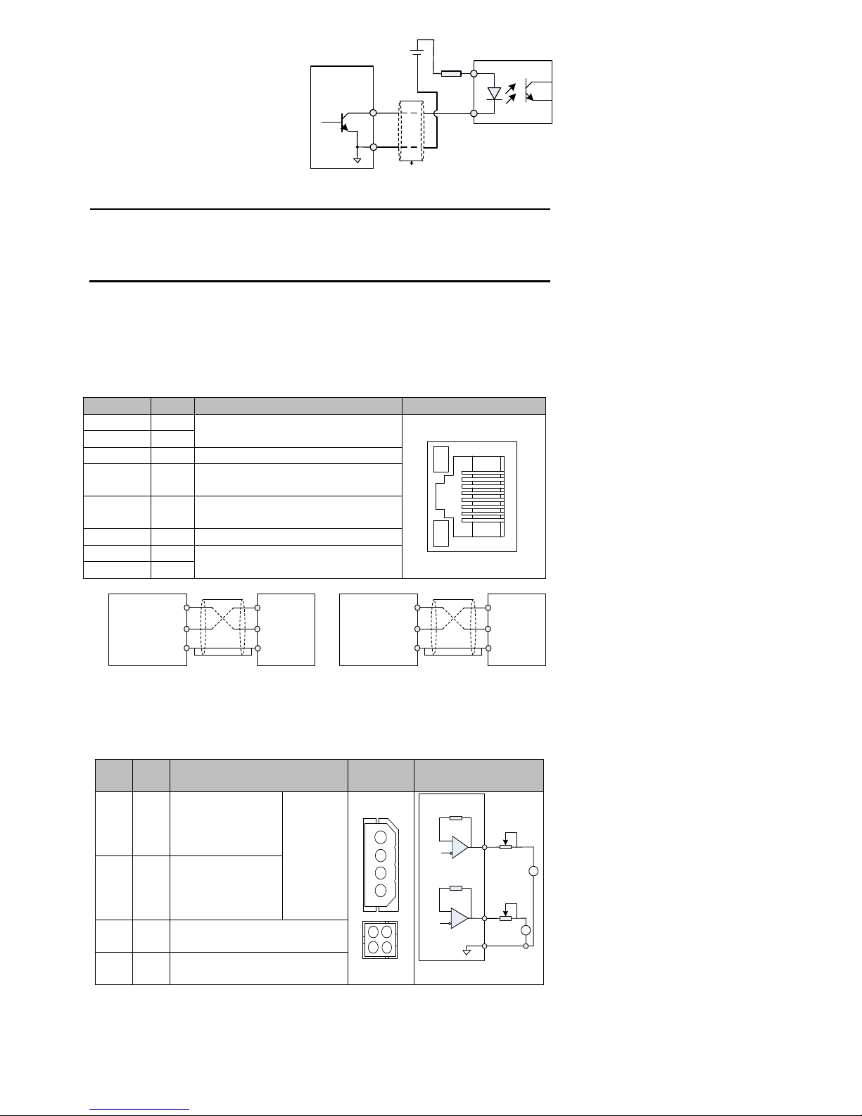
31
Servo drive
35
DC5V~24V
OCZ
42
GND
GND
PE
Figure 4-18 OCZ terminal wiring diagram
Remark:
Be sure that the signal ground of the upper computer should be connected with the ground of
power supply, and shielded twisted-pair cables should be used to reduce noise. The
maximum withstand voltage of drive internal transistor is DC 30V, and the maximum
allowable input current is 40mA.
4.5 CN2, CN3 communication terminal wiring
Drive is connected with the upper computer by CN2, CN3. Users can operate the drive by MODBUS communication, and the communication
distance is about 15m. RS485 can support multiple drives simultaneously online.
Communication signal connectors CN2, CN3 are two same internal, parallel communication signal connectors
Table 4-9 Communication Connector Pin Description
Signal
Pin
function
Terminal pinout
RS485+
1
RS485 Communication port
8
1
RS485-
2
GND
3
Reference ground
RS232-RXD
4
The sender of RS232 is connected with
the receiver upper computer
RS232-TXD
5
The receiver of RS232 is connected with
the sender upper computer
GND
6
Reference ground
CANH
7
CAN Communication port
CANL
8
RS485-
Servo drive
RS485+
GND
upper computer
RS485
communication
interface
+terminal
-terminal
GND
RS232-TXD
RS232-RXD
GND
upper computer
RS485
communication
interface
TXD
RXD
GND
Servo drive
Figure 4-19 Communication terminal wiring
diagram
4.6 CN1 analog output terminal
CN1: there are two different terminals shape, its connection end signal as follows:
Table 4-10 analog output signal description
Signal
name
Pin
Function
Terminal
pinout
wiring
AO1
1
1 analog output, the
output voltage 0V ~
10V, maximum output
current 1mA
Can be set
by P6 group
1
2
3
4
2
3
1
4
Servo drive
AO1
GND
1
2
AO2
3
A
A
AO2
2
2 analog output, the
output voltage 0V ~
10V, maximum output
current 1mA
GND
3
The analog output signal common
ground
Retent
ion
4
Cannot be connected with any
signal line
Remark:
1) After turn off control power, analog monitor output terminal may output voltage of about 5V during 10ms, please note it when using.
2) The maximum output of analog terminal current is 1mA. The drive can be damaged is it is more than 1mA.
Page 32
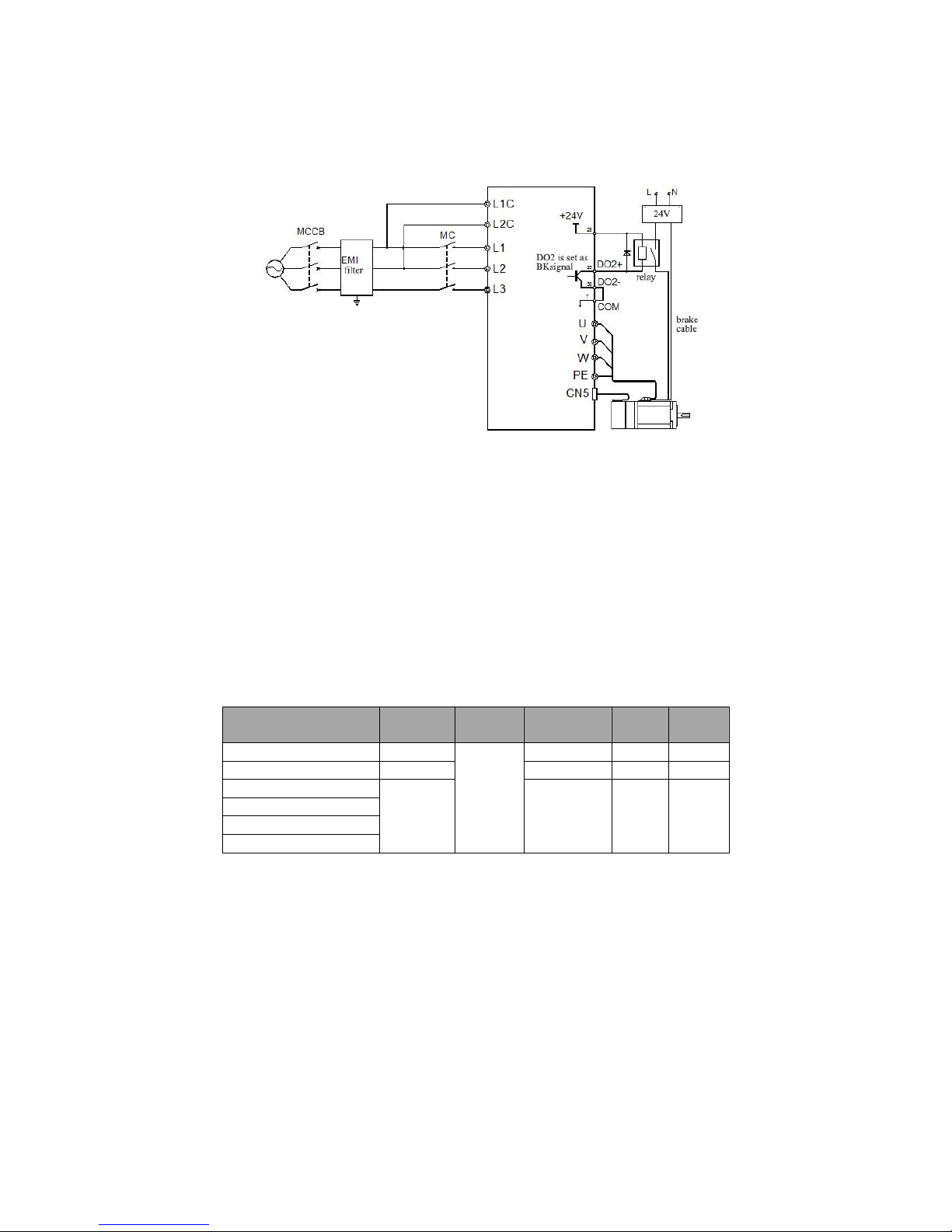
32
4.7 Holding brake
When the motor is used to vertical axis or similar situation, in order to protect the moving parts when loss power, you should use motors with
holding brake.
1. The holding brake is used only to keep the motor stopped, not for stopping the running motor
2. When motors with holding brake running, there may be a clicking sound; it does not affect the function.
Holding brake need an external 24V power supply, brake signal and brake power supply wiring as follows.
Figure 4-20 brake signal and brake power supply wiring
4.7.1 Holding brake Wiring Precautions:
1) The 2nd function (BK) signal terminals (DO2 +, DO2-) should be used to control the intermediate relay. The power supply of brake is
controlled by turning on or off the intermediate relay.
2) There is no polarity of the brake coil, when the brake powered on it is in release state.
3) Be sure to use an external power supply for brake. For Intermediate relay, it can be powered by servo drive internal DC24V,and it is
suggested that don‘t use the one DC24V power supply for both brake and relay
4) When using external power for relay coil, please note DO2 + terminal should be connected to the positive terminal, DO2- terminal
connected to the negative terminal.
5) The input voltage of brake should be at least 21.5V. And it is recommended to use cable more than 0.5mm2 considering the voltage drop
on the cable. Brake specific parameters in Table 3-11.
6) Brake should not to share power supply with other electrical appliances to avoid voltage drop which can lead to braking malfunction.
Table 4-11 Brake datasheets
Model
Holding torque
(Nm)
Voltage
(V)
Power
(W)
Release time
(ms)
Closing time
(ms)
SER06-0R4-30-2□AY1
2.0
24±10%
6.3±7%
150
150
SER08-0R7-30-2□AY1
3.0
10.4±7%
150
150
SER13-1R0-□□-2□BY1
20.0
19.5±7%
200 200
SER13-1R5-□□-□□BY1
SER13-2R0-□□-3□BY1
SER13-3R0-□□-3□BY1
4.7.2 Holding brake operation timing
4.7.2.1 There is a holding brake operation delay. Brake release and closing time please refer to the following diagram
Page 33
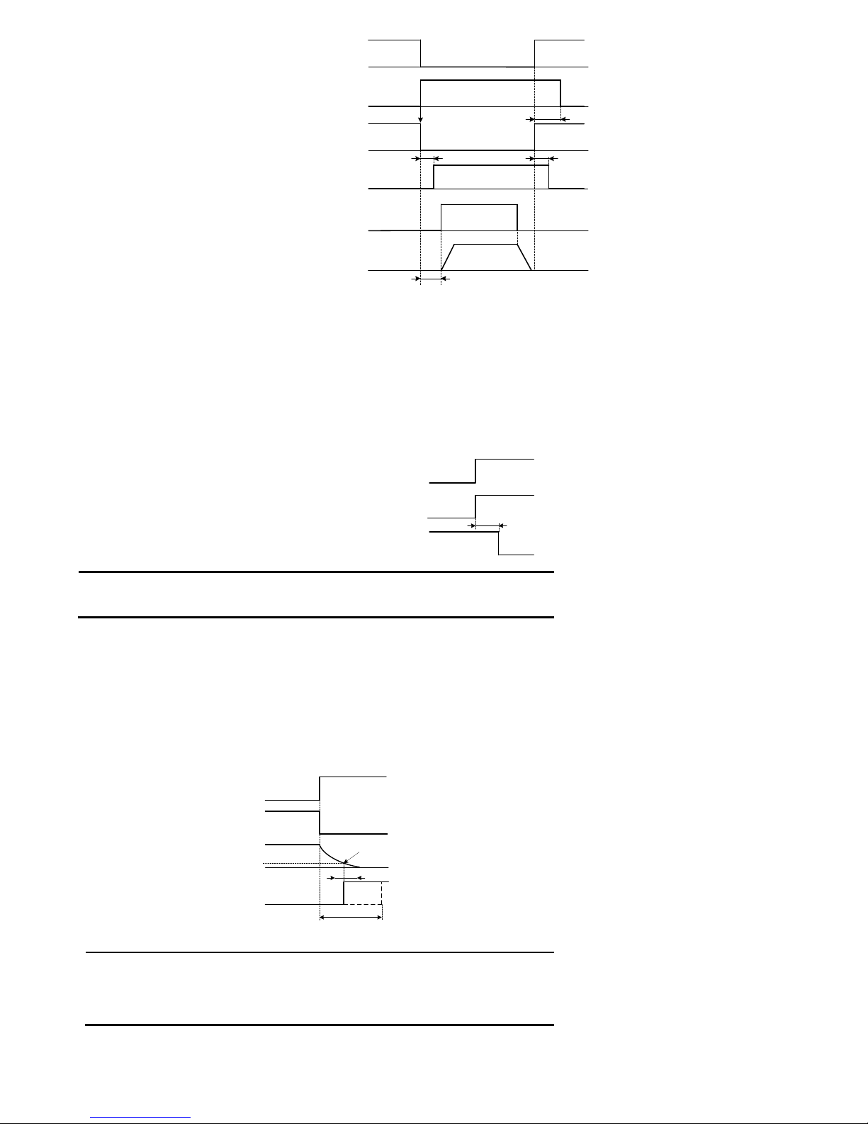
33
Servo enable (/ S-ON) signal
Motor power on
Brake (/BK) instruction
Position / speed /
torque instruction
Motor speed
ON
OFF
P1-55
P1-54
ON
OFF
OFF
OFF
ON
OFF
OFF
Brake
Brake release
(Not brake)
Brake closed
(Brake)
*1 *1
*3
Not receive instruction
receive instruction
0 rpm
*2
Figure 4-21 holding brake release delay time and closing
*1:For different motors, the brake delay time is different. Please refer to table 3-11 and the actual circumstances
*2:It has been set by P1-54 that the time from the servo drive receiving enable (/ S-ON) instruction to it can receive position, speed and torque
instruction should be bigger than the time for brake to release. When the upper computer output instruction to servo motor, please wait until
S-ON signal is ON.
*3:Please set the brake running and the servo OFF time by P1-55, P1-56, P1-57.
4.7.2.2 Servo motor brake signal (/ BK) output time when is stopped
When used in the vertical axis, the weight of moving parts may cause slight movement. By setting P1-55, we can make motor in power off state
after the brake is closed to eliminate the slight movement.
Servo enable (/S-ON)signal
Motor power on
Brake (/ BK) instruction
ON
P1-55
ON
OFF
OFF
Brake release
(open)
Brake closed
(brake)
Figure 4-22 Servo cancel enable the brake operation timing
Remark:
When an alarm occurs, P1-55will be invalid, the servo motor will be in powered off state
immediately. In this case, the movement unit may move before the brake action.
4.7.2.3 Servo motor brake signal (/ BK) output time in rotation
When an alarm occurs in the servo motor rotation, or the servo motor rotation forcibly cancel the enable signal, the servo motor will be in
powered off state immediately. In this case, by setting P1-56 (output speed value brake instruction) and P1-57(servo OFF-brake instruction
waiting time), you can adjust the brake signal (/ BK) output time.
Brake operating condition when the servo motor rotation
When any one of the following condition is satisfied, the brake will be enable:
When the motor is in powered off state, and the speed motor is below the value as P1-56 set.
When the motor is in powered off state, and after a period as P1-57 set.
Motor Power State
Brake (/ BK)
instruction)
Motor speed
ON
P1-56
Brake release
(open)
Brake closed
(brake)
ON
OFF
OFF
Servo enable (/ S-ON) signal
Or Failure
Or Power OFF
Coast to stop
P1-57
Figure 4-23 servo motor brake action during rotation
Remark:
Even the set value in P1-56 is faster than the maximum motor speed, it will also be limit
by the motor speed.
Do not place the motor rotation signal (TGON) and brake signal (BK) to one terminal. If
they are assigned to one terminal, the brake may not work.
Page 34
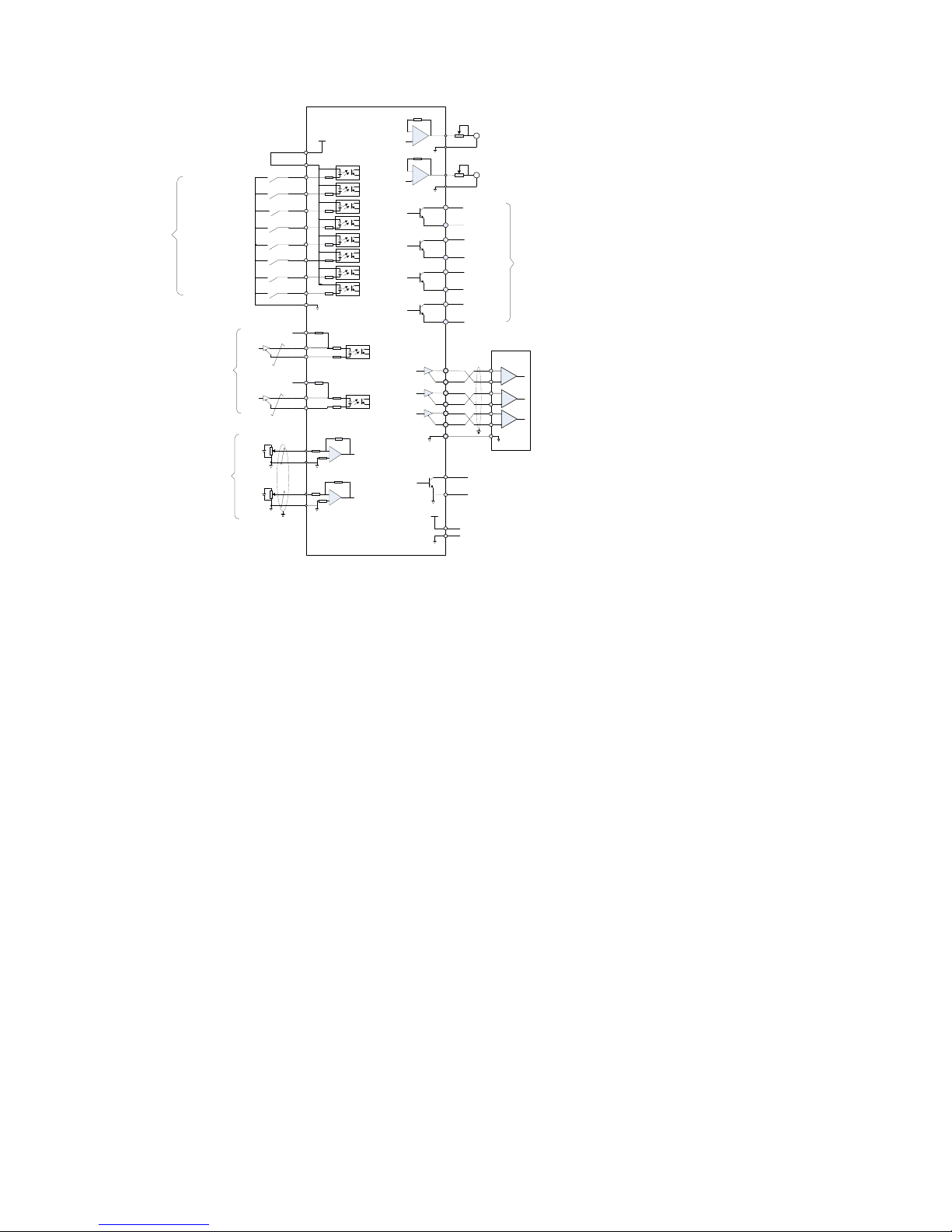
34
4.8 Standard wiring diagram for control circuit
4.8.1 Position control mode standard wiring diagram
100Ω
PULSE+
PULSE-
33
34
SIGN+
SIGN-
31
32
16
PULHIS
PULS
[CW A phase]
SIGN
[CCW B phase]
Position
instruction
8
23
37
38
9
24
39
10
DO1
DO1-
DO2
DO2-
DO3
DO3-
DO4
DO4-
Status
output
Encoder Dividing
pulse output -
Difference
PE
PA+
PAPB+
PB-
PZ+
PZ-
28
13
12
27
26
GND
29
11
35
42
Upper
computer
GND
Encoder Z-phase
open-collector output
GND
OCZ
+5V
+5V
GND
6
43
GND
AO1
Analog 1 output
Analog 2 output
15
29
30
29
GND
GND
AI2
AI1
1
EA100
Servo drive
Servo ready
Brake output
Location arrival
Fault output
Torque
limit
PE
Torque limit 0 ~ 10V
Input impedance : 9kΩ
Torque limit -10 ~ 0V
Input impedance: 9kΩ
Internal + 5V power supply,
the maximum allowable
current 200mA
PULHIP
+24V
+24Vpower supply
25
COM+
21
DI1
5
DI2
20
4
DI3
19
3
18
2
DI4
DI5
DI6
DI7
17
DI8
ALM-RST
INHIBIT
P-OT
N-OT
GNUMO
GNUM1
S-ON
P-CLR
COM
State
input
7
Servo enable
Alarm reset clear
Pulse deviation counter clear
Pulse inhibit
Forward driving inhibit
Reversal driving
inhibit
Electronic gear ratio numerator
selection 0
Electronic gear ratio numerator
selection 1
S-RDY
BK
COIN
ALM
2KΩ
2KΩ
A
GND
AO1
A
100Ω
100Ω
100Ω
Figure 4-24 standard position mode control circuit wiring diagram
4.8.2 Speed Control Mode Standard Wiring Diagram
Page 35
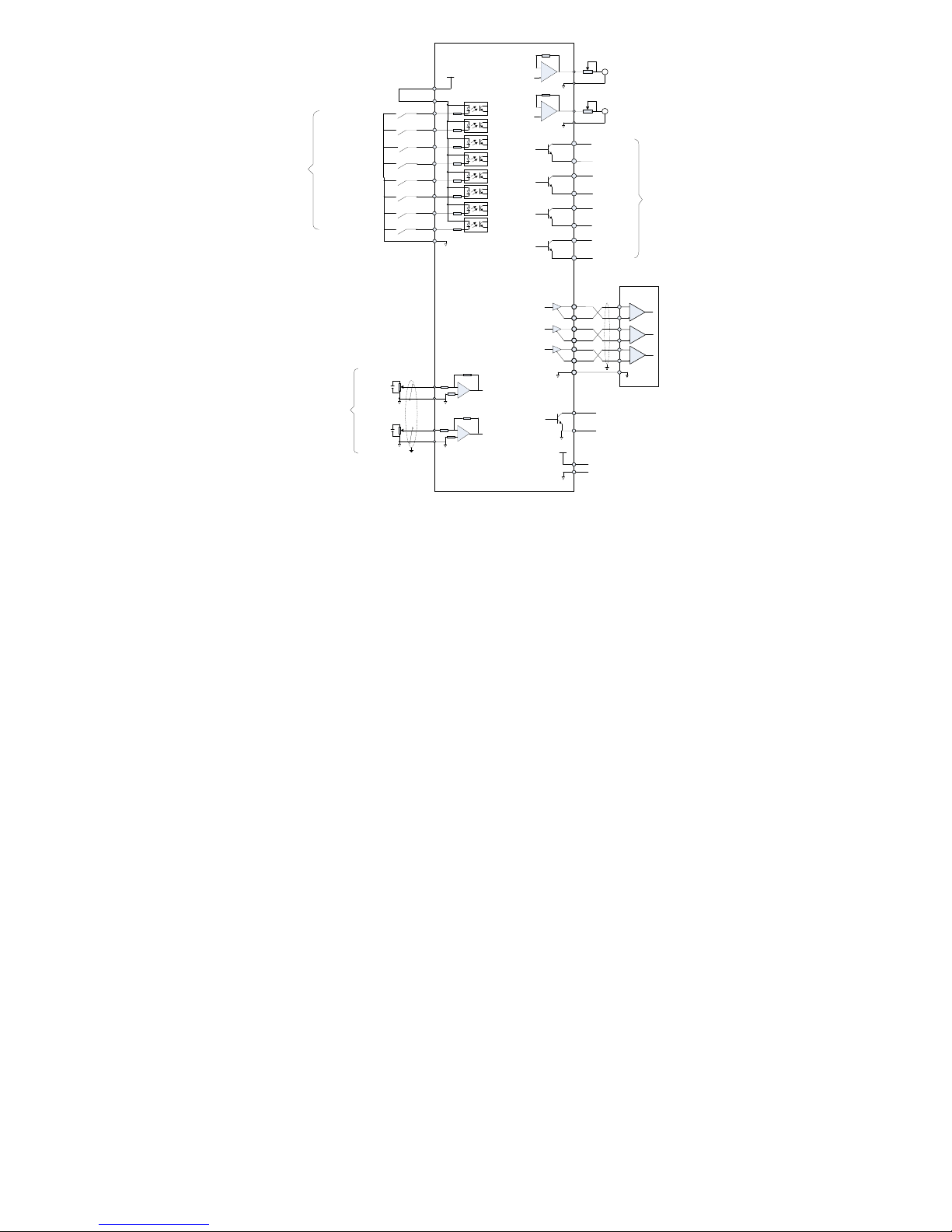
35
8
23
37
38
9
24
39
10
DO1
DO1-
DO2
DO2-
DO3
DO3-
DO4
DO4-
Status
output
Encoder Dividing
pulse output -
Difference
PE
PA+
PAPB+
PB-
PZ+
PZ-
28
13
12
27
26
GND
29
11
35
42
Upper
computer
GND
Encoder Z-phase open-
collector output
GND
OCZ
+5V
+5V
GND
6
43
GND
AO1
Analog 1 output
Analog 2 output
15
29
30
29
GND
GND
AI2
AI1
EA100
Servo drive
Servo ready
Brake output
Torque arrival
Fault output
PE
Internal + 5V power supply,
the maximum allowable
current 200mA
+24V
+ 24V power supply
25
COM+
21
DI1
5
DI2
20
4
DI3
19
3
18
2
DI4
DI5
DI6
DI7
17
DI8
ALM-RST
N-OT
DIR-SEL
TDIR-SEL
S-ON
P-OT
COM
State
input
7
Servo enable
Alarm reset clear
Forward driving inhibit
Reversal driving inhibit
Speed instruction
direction selection
Torque instruction
direction selection
S-RDY
BK
Tcmp
ALM
A
GND
AO1
A
Speed
instruction
Analog speed given
Signal Input: ± 10V
Input impedance about: 9kΩ
Analog speed limit
Signal Input: ± 10V
Input impedance about: 9kΩ
Figure 4-25 standard speed mode control circuit wiring diagram
4.8.3 Torque Control Mode Standard Wiring Diagram
Page 36
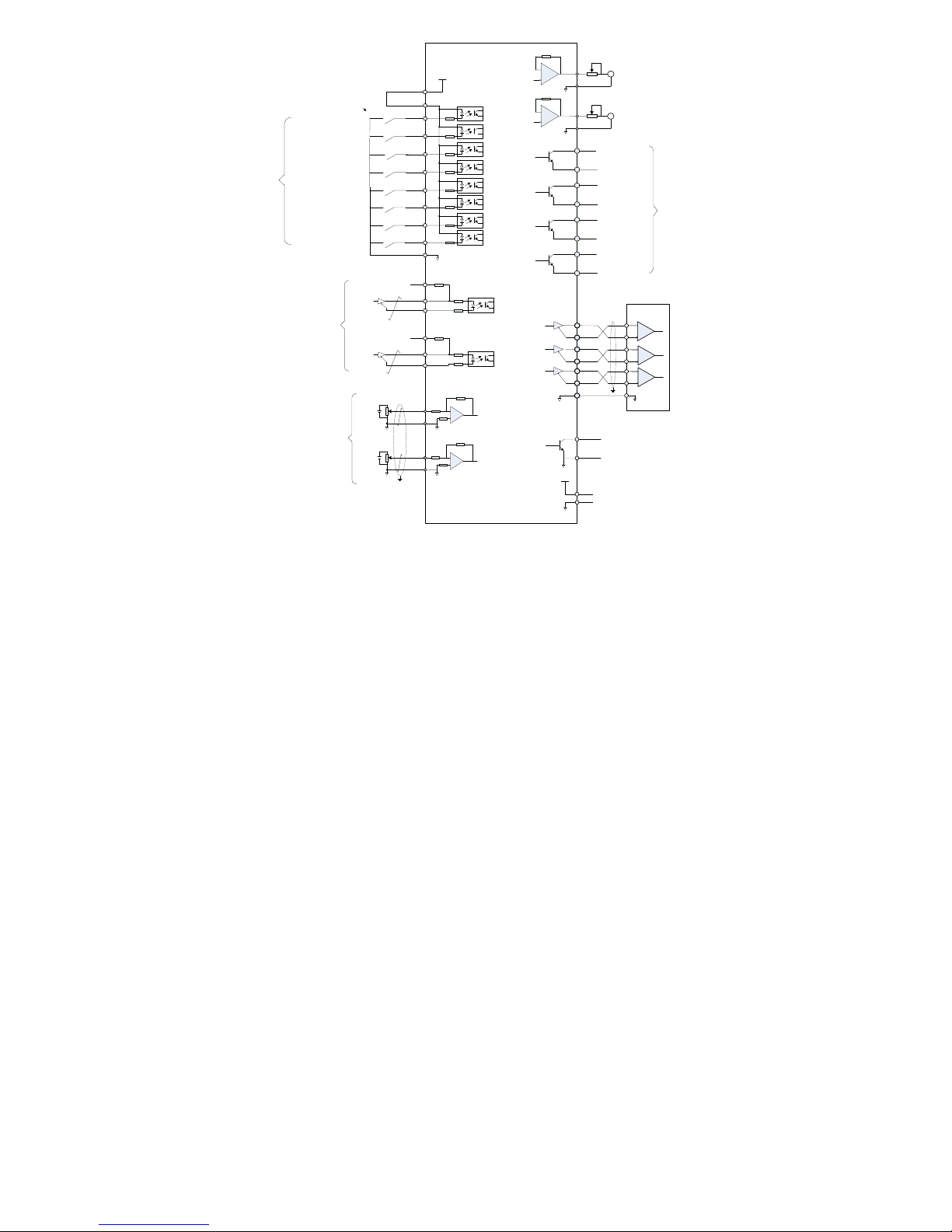
36
100Ω
PULSE+
PULSE-
33
34
SIGN+
SIGN-
31
32
16
PULHIS
PULS
[CW A phase]
SIGN
[CCW Bphase]
Torque
instruction
8
23
37
38
9
24
39
10
DO1
DO1-
DO2
DO2-
DO3
DO3-
DO4
DO4-
Status
output
Encoder
Dividing
pulse output
- Difference
PE
PA+
PA-
PB+
PB-
PZ+
PZ-
28
13
12
27
26
GND
29
11
35
42
Upper
computer
GND
Encoder Z-phase
open-collector output
GND
OCZ
+5V
+5V
GND
6
43
GND
AO1
Analog 1 output
Analog 2 output
15
29
30
29
GND
GND
AI2
AI1
1
EA100
Servo drive
Servo ready
Brake output
Location arrival
Fault output
Torque
limit
PE
Torque limit 0 ~ 10V
Input impedance about:
9kΩ
Torque limit -10 ~ 0V
Input impedance about:
9kΩ
Internal + 5V power
supply, the maximum
allowable current 200mA
PULHIP
+24V
+24V电源
25
COM+
21
DI1
5
DI2
20
4
DI3
19
3
18
2
DI4
DI5
DI6
DI7
17
DI8
ALM-RST
INHIBIT
P-OT
N-OT
GNUMO
GNUM1
S-ON
P-CLR
COM
State
input
7
Servo enable
Alarm reset clear
Pulse Deviation counter clear
Pulse inhibit
Forward Drive inhibit
Reverse drive inhibit
Electronic gear ratio numerator
selection 0
Electronic gear ratio numerator
selection 1
S-RDY
BK
COIN
ALM
2KΩ
2KΩ
A
GND
AO1
A
100Ω
100Ω
100Ω
Figure 4-26 standard torque mode control circuit wiring diagram
4.9 Control circuit wiring precaution
Encoder cable routing must be separated from the power cable routing by at least 30cm or more.
If the control circuits need to extend, make sure the shield is reliable connected.
In the servo drive, + 24V COM and + 5V reference to GND. Do not exceed the maximum allowable load current, otherwise the drive may
be broken.
Try to use the shortest command input and encoder cable.
Please use the cable more than 1.5mm2 for grounding cable.
Must be a single-point ground.
4.10 Servo drive main circuit block diagram
Page 37
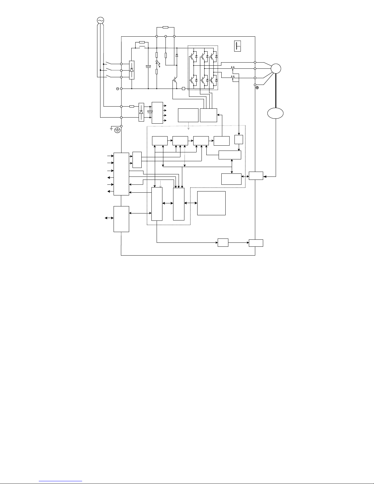
37
Operation panel
CN4
CN2/
CN3
CN1
CN5
M
Encoder
Servo
Motor
Rectifier
circuit
+
P
External braking resistor
Servo drive
Regenerative
processing
circuit
IGBT
U
V
W
GATE
DRIVER
Protection
circuit
L1
L2
L3
Control
Power
+15V
+5V
+3.3V
+24V
L1C
L2C
A/D
Position
control
Speed Control
Current
Control
To DSP
PWM
DSP
CPLD
From
Protection
circuit
Data Bus
External speed
External torque
Position pulse
A, B, Z output
Digital input
Digital Output
Analog Output
D/A
Current Signal
Processing
A/D
The encoder
signal processing
D C
24V
fan
Power supply
1/3-phase 220V
3-phase 380V
RS232
RS485
Built-in
braking
resistor
Figure 4-27 servo drive main circuit diagram
Page 38
38
5 Running and debugging
Before connecting the load, according to the commands in this manual, make sure that the motor running normally, then you can connect the
motor with load.
Usually a servo drive can be put into using after the following tests.
1) Wiring, checking.
2) Drive power on, adjust the parameters.
3) No-load running.
4) Control function debugging.
Strongly recommended: please make sure that the motor running normally without load
at first, then connect the motor with load to avoid unnecessary danger!
5.1 Drive power on
5.1.1 before power on
1) Check whether drive and motor are matched (check their specifications).
2) L1, L3, L2 and U, V, W, cannot connect conversely, and check whether these terminals are loose.
3) U, V, W of the motor must be correctly connected to the U, V, W of the drive.
4) Check whether the input voltage is corresponding with the nameplate or panel of drive.
5) Encoder terminal should be connected correctly.
6) The servo motor and driver should be well grounded.
5.2 Trial running
5.2.1 Parameters setting
Parameter
Name
P8-02
JOG function open
P8-03
JOG speed setting
Cancel the servo enable, and then enter the JOG mode to operate in the following diagram.
UP DOWN
Press“DOWN”key, the
motor will run forward in the
speed set as P8-03
For security reasons,
the speed should be
less than 500rpm!!!
SET
Jog speed
Press“UP”key,motor run
as the speed of the P8-03
setting value
P8-03
P8-02
JOGEn
JOG Operation
If the motor runs normally then you can do next step. If they did not run normally, please check the system wiring, including phase sequence of
motor control wiring, the encoder wiring. Repeat the above steps. If it still cannot run normally, please contact the manufacturer to solve it.
5.3 Servo enable method
There are three ways to make the servo drive enable:
1) After the servo drive is powered up, set P8-05 parameter to 1. The servo drive can be enable immediately, but parameter P8-05will
automatically restore to 0 when power off;
2) The input terminal DI1 is the default servo enable terminal. Setting P6-01=00001, so that the DI1 terminal is closed, servo drive can be
enable, and valid after restart;
3) The input terminal DI1 is the default servo enable terminal. When using internal 24V power supply, the 24V and COM should be shorted,
servo drive can enable.
5.3.1 Position control mode
According to the command mode and operation characteristics of the servo drive, there are three kinds of operation modes, namely, position
control mode, speed control mode and torque control mode.
In position control mode, the displacement is generally controlled by the number of external input pulse, and the rotational speed is controled by
the external input pulse frequency. Because the position mode can be used for speed and position control, it is generally applied to positioning
device. It is the most widely used mode. It is mainly used for the robot hand, chip machine, engraving and milling engraving, CNC machine
tools, etc…
5.3.2 Position control mode steps
1) Wiring according with chapter 3.10 ;
2) Set P1-00 to 1 (position control mode, the default value is 1), set P1-01 to 0 (external pulse is given, the default value is 0);
3) Set P1-02 to 0 (pulse + direction control mode, the default value is 0) or other mode for the user;
4) Set the electronic gear ratio. P1-27 is set for molecular (default is 1). P1-28 is set for denominator (default is 1), the default pulse for one
Page 39
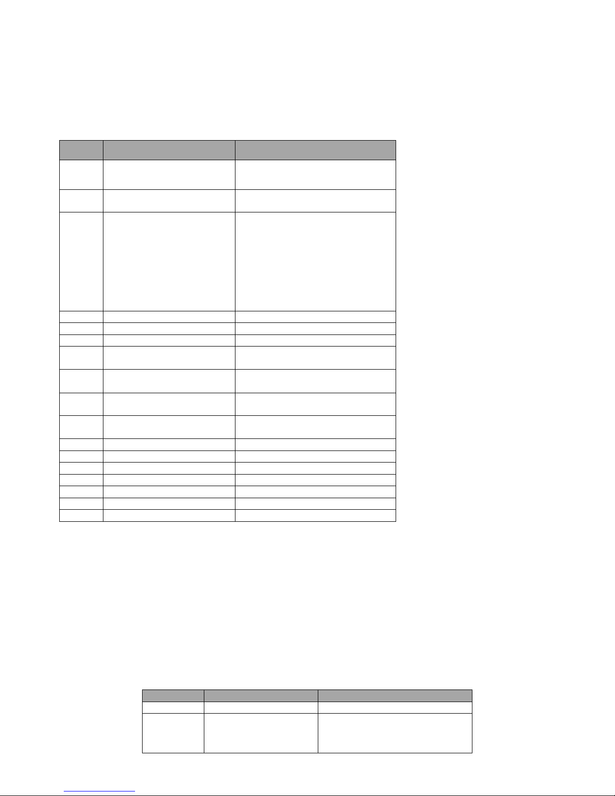
39
motor rotating circle is 10000.
a) If P1-27 = 10, P1-28=1, the motor rotates one circle with 1000 external pulse input
b) If the P1-27=1, P1-28=10, the motor rotates one circle with 100000 external pulse input
5) Enable drive. Keep DI1 and COM which are in the CN4 terminal short connected, the drive will enable (DI1is the default servo enable
terminal, the user can modify it by function code).
5.3.3 Position control mode when the main function code
Table 5-1 Main function code for position control mode
Function
code
Setting value
Description
P1-00
1:Position control mode
Control mode selection
P1-01
0:External command (Default)
1:Internal instruction
Position command source
P1-02
0:Pulse + direction,positive logic
(default value)
1:Pulse + direction,negative logic
2:Two phase orthogonal pulse (4
times of frequency), positive
3:Two phase orthogonal pulse (4
times of frequency), negative
4:CCW/CW pulse, positive logic
5:CCW/CW pulse, negative logic
External pulse input form
P1-27
User Setting,Default value 1
Electronic gear molecular
P1-28
User Setting,Default value 1
Electronic gear denominator
P1-33
User Setting,Default value 10
Positioning complete width
P1-36
User Setting,Default value 25000
Alarm threshold of position following
deviation
P1-37
User Setting,Default value 25000
Fault threshold of position following
deviation
P1-53
0:Free stopping(Default value)
1:Stopping at zero speed
Stop mode
P1-15
User Setting,Default value 0
External pulse instruction smoothing filter
time constant
P1-46
User Setting,Default value 300
Forward maximum torque limit
P1-47
User Setting,Default value 300
Reverse maximum torque limit
P5-00
User Setting,Default value 30
Position regulator proportional gain KPP
P5-02
User Setting,Default value 0
Front position regulator feedforward gain
P5-03
User Setting,Default value 5
Position feedforward smoothing time
P5-04
User Setting,Default value 350
Speed regulator proportional gain KVP
P5-05
User Setting,Default value 10
Speed regulator integration time constant
5.4 Speed control mode
In speed control mode, the rotational speed is controlled by analog input, digital input, and communication. It is mainly used in some constant
speed situation. Such as the application of the analog engraving and milling machine, the position control is achieved by the upper computer, the
servo drive works in speed control mode.
5.4.1 Speed control mode:
1) According to the wiring of section 3.10.
2) Servo JOG test run through the key to confirm the normal operation of the motor.
3) Refer to the section 3.10.2 wiring for the necessary DI/DO and analog terminals for connecting CN4.
4) To carry out the relevant setting of speed mode.
5) To enable the servo drive, and then first make the motor rotate at low speed, determine whether the rotation direction of the motor is
normal, and then adjust the gain.
5.4.2 Speed control mode main function code:
Speed control mode when the main function code
Function code
Reference value
Description
P1-00
0: Speed control mode
Control mode is speed control
P1-05
0: Internal digital given
1: Analog value 1 given
2: Analog value 2 given
3: Not used
Select the speed command source
Page 40
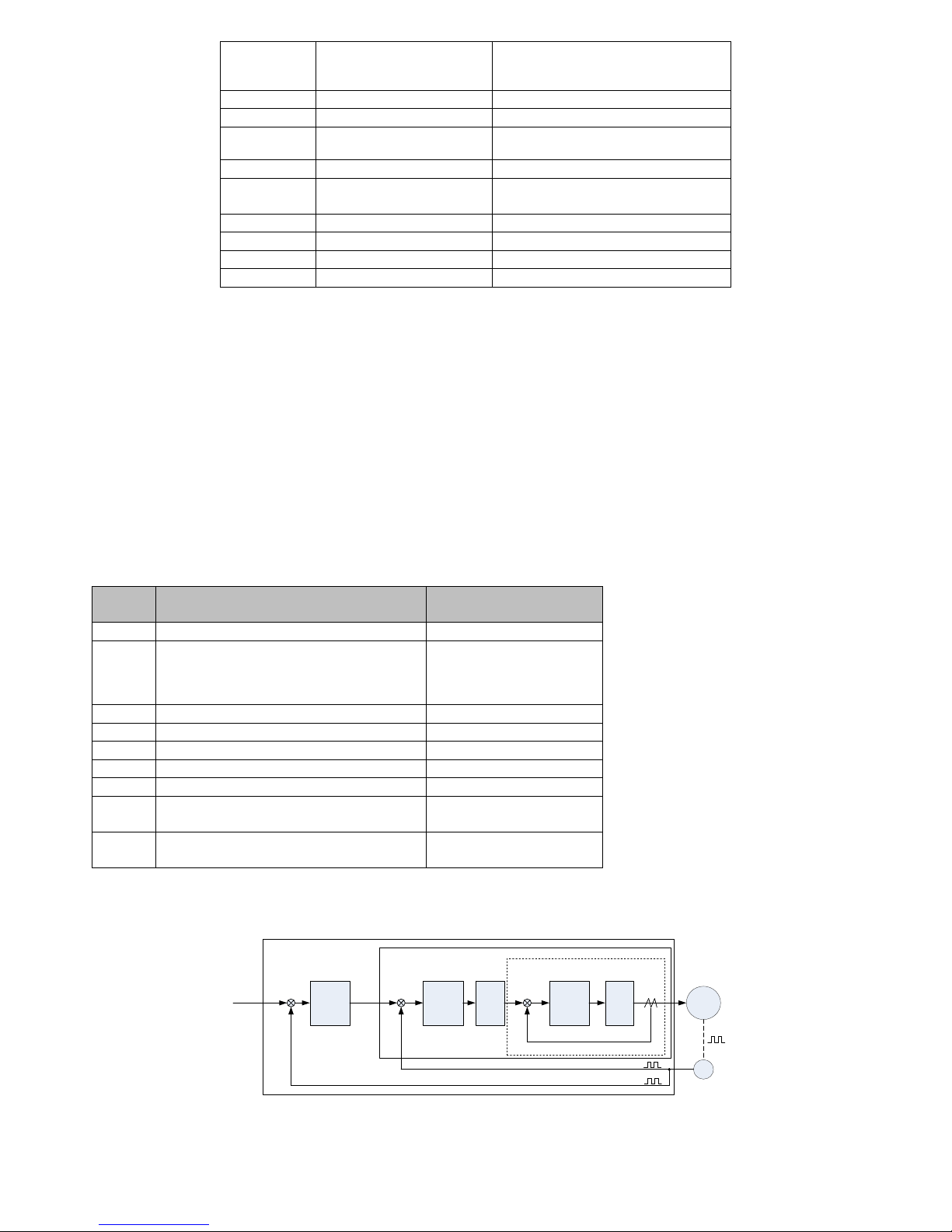
40
4: Internal multi section speed
command
5: Point running
P1-16
100ms
Speed instruction acceleration time T
SACC
P1-17
100ms
Speed instruction deceleration time T
SDEC
P1-18
10ms
Speed instruction S curve smoothing time
TSL
P3-00~P3-31
When using the internal speed
Internal Multi-speed parameters
P1-53
0:Free stopping
1:Stopping at zero speed
Stop mode
P1-46
300%
Forward maximum torque limit
P1-47
300%
Reverse maximum torque limit
P5-04
350
Speed regulator proportional gain KVP
P5-05
10
Speed regulator integration time constant
5.5 Torque control mode debugging steps
The torque control mode is the size of the output torque of the motor. Mainly used in the material of the force has strict requirements of the
winding and winding device, such as winding device or pull fiber device, some tension control occasions, torque setting according to the change
of the radius of the winding change, to ensure that the material force will not change with the radius of the wound.
5.5.1 Torque control mode debug step:
1) According to the wiring of section 3.10
2) Servo JOG test run through the key to confirm the normal operation of the motor.
3) Refer to the section 3.10.3 wiring commands for the DI/DO and the source of the torque command, speed limit, etc..
4) To carry out the relevant setting of the torque mode.
5) Enable the servo, and then set a lower speed limit value, give a forward or reverse torque command to the servo application, make confirm
whether the motor rotation direction and speed are correct, if it‘s normal , then you can start to use.
5.5.2 Mainly related to the function codes of torque control mode:
Mainly related to the function codes of torque control mode
Function
code
Reference value
Description
P1-00
2: Torque control mode
Control mode selection
P1-48
0: Internal limit [P1-46, P1-47]
1: Analog 1 limit, while limited by P1-46, P1-47
2: Analog 2 limit, while limited by P1-46, P1-47
3: Not used
Torque limit source selection
P4-00
100%
Internal digital torque given
P4-01
100rpm
Speed limit of torque control
P1-22
100us
Speed limit of torque control
P1-46
300%
Forward maximum torque limit
P1-47
300%
Reverse maximum torque limit
P5-04
350
Speed regulator proportional
gain KVP
P5-05
10
Speed regulator integration time
constant
5.6 Gain parameter adjustment strategy
The drive includes three control loops: current loop, speed loop and position loop. The control block diagram is as follows:
Position
controll
er
Speed
controllerFilter
Current
controll
er
Powe
r
conv
ersio
n
M
PG
Current
loop
Speed
loop
Position
loop
Position
instruction
Speed
instruction
+
-
+
-
+
-
Servo
motor
Current
detect
Three block diagram of servo system
In theory, the inner control loop bandwidth must be higher than the outer, otherwise the whole control system will be unstable and cause
vibration or is a response to the poor, so three control loop bandwidth relationship should be as follows:
Bandwidth of position loop < Bandwidth of speed loop < Bandwidth of current loop
Page 41
41
Since the drive has been adjusted to the current control loop in the best state, the user only needs to adjust the control parameters of speed loop
and position loop.
5.6.1 Gain adjustment procedure
The choice of position and speed bandwidth must be decided by the mechanical rigidity and applications, connected by a belt conveying
mechanical rigidity and lower and can be set to a low bandwidth; driven by the speed reducer of the ball screw rod of the mechanical stiffness of
the medium can be set to medium bandwidth; to drive directly to the ball screw rod or linear motor stiffness is higher, can be set to high
bandwidth. If the properties of machine is unknown, can gradually increase the gain to improve the bandwidth and gain can be lowered until
resonance.
In each gain of servo drive, if one parameter is changed, other parameters are also should be adjusted. Please don't make a big change to one
parameter. Regarding the change steps of servo parameters, please follow the following principles:
Improve response
Reduce response, suppress vibration and
overshoot
1.Increase the proportion of speed regulator
P5-04
1.lower position regulator proportional gain
P5-00
2.Reduce the speed regulator integral time
constant P5-05
2.Increasing speed regulator integral time
constant P5-05
3.Improve the position regulator
proportional gain P5-00
3.Reduce the speed regulator P5-04
5.6.2 Speed gain adjustment procedure
1) Setting load inertia ratio of P5-08.
2) Setting speed regulator integral time constant P5-05 for larger values.
3) In the range of no vibration and strange noise to adjust P5-04(Speed controller proportional gain) higher, if there is a slight, you should
adjust the P5-04 smaller.
4) In the range of no vibration to adjust P5-05(Speed controller integral time constant) smaller, if there is a slight, you should adjust the
P5-05 higher.
5) If the mechanical system is unable to adjust the gain due to resonance and other reasons, it cannot get the desired response, the torque low
pass filter or notch filter to adjust the suppression of resonance, and then in order to improve the response, need to do the above steps
again. First, try to use low pass filter, if the effect is not good, then try to use notch filter.
5.6.3 Position control gain adjustment procedure
1) Setting load inertia ratio of P5-08.
2) Setting speed regulator integral time constant P5-05 for larger values.
3) In the range of no vibration and strange noise to adjust P5-04(Speed controller proportional gain) higher, if there is a slight, you should
adjust the P5-04 smaller..
4) In the range of no vibration to adjust P5-05(Speed controller integral time constant) smaller, if there is a slight, you should adjust the
P5-05 higher.
5) Increase the position regulator proportional gain P5-00, if there is a slight, you should adjust it smaller.
6) If the mechanical system is unable to adjust the gain due to resonance and other reasons, it cannot get the desired response, the torque low
pass filter or notch filter to adjust the suppression of resonance, and then in order to improve the response, need to do the above steps
again. First, try to use low pass filter, if the effect is not good, then try to use notch filter.
7) The position feed forward gain P5-02 can be adjusted properly if the positioning time is shorter and the position error is smaller.
Page 42
42
6 Function Parameters
6.1 Function parameters define
Function parameters are divided into the following 11 groups. The first code after starting code P is the group number. The next two
parameters is the group internal number. The address is consisted of the group parameters and group internal parameters. The functional
groups are defined as follows:
P0-xx group: Monitoring parameters
P1-xx group: Basic parameters
P2-xx group: Internal multi segment position control parameters
P3-xx group: Internal multi segment speed control parameters
P4-xx group: Torque control parameters
P5-xx group: Gain tuning parameters
P6-xx group: Input / output setting parameters
P7-xx group: Communication parameters
P8-xx group: Auxiliary function parameters
Pb-xx group: Origin return function parameters
PE-xx group: Motor parameters
Function parameter set attribute description:
(○): Set at any time, take effect immediately
(●): Set at any time, take effect when repower
(☆): Set at any time, take effect when repower
(□): Set when stop, take effect immediately
(■): Set when stop, take effect when repower
(▢): Read only, cannot set
Control mode description:
P—Position control mode
S—Speed control mode
T—Torque control mode
6.2 Function parameter list
6.2.1 P0 group - Monitoring parameters
Parameters
Function
Initial
value
Unit
Applicable
control
mode
Property
Communicatio
n
Address
P S T
P0-00
Motor speed
0
rpm √ √ √ ▢
0000H
P0-01
Motor load rate
0 % √ √ √
▢
0001H
P0-02
Current electric angle
0 ° √ √ √
▢
0002H
P0-03
DI Input level (binary display)
Low bit:
11111
High bit:
11111
- √ √ √ ▢
0003H
P0-04
DO Output level (binary display)
Low bit:
11111
High bit:
1
- √ √ √ ▢
0004H
P0-05
Encoder multi circle position
value (only for 17 bit absolute
encoder)
0
rev √ √ √ ▢
0005H
P0-06
Total running time
0
min √ √ √ ▢
0006H
P0-08
AI1 voltage value
0
mV √ √ √ ▢
0008H
P0-09
AI2 voltage value
0
mV √ √ √ ▢
0009H
P0-10
Encoder sector number (only for
2500ppr incremental encoder)
0 - √ √ √
▢
000AH
P0-11
Bus voltage
0 V √ √ √
▢
000BH
P0-12
Effective current value
0 A √ √ √
▢
000CH
P0-13
Servo drive current state
- - √ √ √
▢
000DH
P0-14
Brake load ratio
0 % √ √ √
▢
000EH
P0-15
IGBT module temperature
0 ℃ √ √ √
▢
000FH
P0-16
Total collected external pulse
0
ppr √ ▢
0010H
P0-18
Display P1-60 selected fault
codes
- - √ √ √
▢
0012H
Page 43
43
Parameters
Function
Initial
value
Unit
Applicable
control
mode
Property
Communicatio
n
Address
P S T
P0-19
Speed when P1-60 failure occurs
0
rpm √ √ √ ▢
0013H
P0-20
Bus voltage when P1-60 fault
occurs
0 V √ √ √
▢
0014H
P0-21
Effective current when P1-60
fault occurs
0 A √ √ √
▢
0015H
P0-22
Running time when P1-60 fault
occurs
0
min √ √ √ ▢
0016H
P0-24
Low 4 bit of encoder single-turn
position value (only for 17 bit
encoder)
0
ppr √ √ √ ▢
0018H
P0-25
High 5 bit encoder single-turn
position value (only for the 17
encoder)
0
ppr √ √ √ ▢
0019H
P0-26
The current total inertia load continuous detection
0
kg*c
m2
√ √
▢
001AH
P0-27
Current load inertia ratio continuous detection
0 % √ √
▢
001BH
P0-28
Total number of feedback pulses
0
ppr √ ▢
001CH
P0-30
Received external pulse
frequency
0
Khz √ ▢
001EH
6.2.2 P1 group - Basic control parameters
Parameters
Function
Initial
value
Unit
Applicable
control
mode
Property
Communica
tion
address
P S T
P1-00
Control mode selection:
0: Speed control mode
1: Position control mode
2: Torque control mode
3: Speed position switching mode
4: Torque speed switching mode
5: Position torque switching mode
1 - √ √ √
○
0100H*
2100H*
P1-01
Position command source selection:
0: external pulse command (pt)
1: internal multiple command (pr)
0 - √ ○ 2101H
P1-02
External pulse command input form:
0: Pulse + direction, positive logic
1: Pulse + direction, negative logic
2: Two phase orthogonal pulse (4
times
of frequency), positive logic
3: Two phase orthogonal pulse (4
times
of frequency), negative logic
4: CCW/CW pulse, positive logic
5: CCW/CW pulse, negative logic
0 - √ ● 2102H
P1-03
Internal position command multiple
execution options:
0: From pr1 to pr16, cycle
1: From pr1 to pr16, not cycle
2: External Di switch
0 - √ ○ 2103H
P1-05
Speed command source:
0: Internal digital given (P3-00
given)
1: Analog quantity 1 given (AI1)
2: Analog quantity 2 given (AI2)
3: Not used
4: Internal multi section speed
command
5: Point running (should make
external JOG DI enable)
0 - √ ○ 2105H
P1-06
Multi section speed selection:
0: Multi section speed automatic
switching, cycle
0 - √ ○ 2106H
Page 44
44
Parameters
Function
Initial
value
Unit
Applicable
control
mode
Property
Communica
tion
address
P S T
1: Multi section speed automatic
switch,
not cycle
2: Multi section speed external Di
switch
P1-07
Frequency dividing output
2500
ppr √ √ √ ●
2107H
P1-08
Torque command selection:
0: Internal digital given (given by
P4-00)
1: Analog value 1 given (AI1)
2: Analog value 2 given (AI2)
3: Not used
0 - √ ○ 2108H
P1-09
Speed feedback filter time constant
500
us √ √ √ ○
2109H
P1-10
First group of resonance frequency
setting value
1000
Hz √ √ ○
210AH
P1-11
First group of resonance points in the
notch depth
0
dB √ √ ○
210BH
P1-12
Internal position command
acceleration time T
PACC
100
ms √
☆ 210CH
P1-13
Internal position command
deceleration time T
PDEC
100
ms √
☆ 210DH
P1-14
Internal position command S curve
smoothing time TPL
10
ms √
☆ 210EH
P1-15
External pulse command smoothing
filter time constant
0
ms √ ○
210FH
P1-16
Speed command acceleration time
T
SACC
200
ms √
☆ 2110H
P1-17
Speed command deceleration time
T
SDEC
200
ms √
☆ 2111H
P1-18
Speed command S curve smoothing
time TSL
50
ms √
☆ 2112H
P1-19
Speed command low-pass filter
smoothing filter time constant
10. 0
ms √
○ 2113H
P1-20
Analog speed command gain
3000
rpm √ ○
2114H
P1-21
Current feedback low-pass
smoothing constant
100
us √ √
√ ○ 2115H
P1-22
Torque command low-pass
smoothing constant
100
us √ √
√ ○ 2116H
P1-23
The torque command when analog
maximum input (10V)
100 % √ ○ 2117H
P1-24
Second group of resonance
frequency setting value
1000
Hz √ √ ○
2118H
P1-25
Second group of resonance points in
the notch depth
0
dB √ √ ○
2119H
P1-26
Electronic gear ratio factor
0 - √ ○ 211AH
P1-27
Electronic gear molecular 1
1 - √
○
011BH*
211BH*
P1-28
Electronic gear denominator
1 - √
○
011CH*
211CH*
P1-29
Electronic gear molecular 2
1 - √
○
011DH*
211DH*
P1-30
Electronic gear molecular 3
1 - √
○
011EF*
211EH*
P1-31
Electronic gear molecular 4
1 - √
○
011FH*
211FH*
P1-32
Position approaching width
When the fault counter is less than
the setting value, it will export
position approaching signal
20
ppr √ ○
2120H
P1-33
Position complete width
10
ppr √ ○
2121H
P1-34
Action selection to remove position
deviation by external DI signal
0: By rising edge of P-CLR
1: By low level of P-CLR
2: By high level of P-CLR
0 - √ ○ 2122H
Page 45
45
Parameters
Function
Initial
value
Unit
Applicable
control
mode
Property
Communica
tion
address
P S T
3: By falling edge of P-CLR
P1-35
Automatic selection of position
deviation:
0: Automatically remove deviation
only when fault occurs
1: Automatically remove deviation
when fault occurs or servo cancel
enable
2: No automatically remove
deviation,
and remove deviation as P1-34 set
1 √ ○ 2123H
P1-36
Alarm threshold of position
following deviation
25000 256
ppr
√ ○ 2124H
P1-37
Fault threshold of position following
deviation
25000 256
ppr
√ ○ 2125H
P1-38
Threshold of torque reaches
0 % √ ○ 2126H
P1-39
Maximum speed setting (over-speed
setting value)
5000
rpm √ √ √ ○
2127H
P1-40
Zero speed signal output value
10
rpm √ √ √ ○
2128H
P1-41
Rotation signal output value
10
rpm √ √ √ ○
2129H
P1-42
Speed approaching threshold
100
rpm √ ○
212AH
P1-43
Speed reach threshold
20
rpm √ ○
212BH
P1-44
Zero fixed value of analog speed
command
10
rpm √ ○
212CH
P1-45
Z Pulse output width
0
0.
5ms
√ √ √ ● 212DH
P1-46
Forward maximum torque limit
300 % √ √ √ ○ 212EH
P1-47
Reverse maximum torque limit
300 % √ √ √ ○ 212FH
P1-48
Torque limit source selection;
0: Internal limit [P1-46, P1-47]
1: Analog 1 limit, while limited by
P1-46, P1-47
2: Analog 2 limit, while limited by
P1-46, P1-47
3: Not used
0 - √ √ √ ○ 2130H
P1-49
Third group of resonance frequency
setting value
1000
Hz √ √ ○
2131H
P1-50
Third group of resonance points in
the notch depth
0
dB √ √ ○
2132H
P1-53
Stop mode selection
0: When servo OFF, free stopping;
1: When servo OFF, stopping at zero
speed
0 - √ √ √ ○ 2135H
P1-54
Delay time of Servo ON-receive
command
200
ms √ √ √ ○
2136H
P1-55
Delay Time of Servo OFF-braking
command
200
ms √ √ √ ○
2137H
P1-56
Speed brake command output speed
50
rpm √ √ √ ○
2138H
P1-57
Waiting time of Servo OFF-Brake
command
500
ms
P1-58
Direction selection of frequency
dividing output pulse
0 - √ √ √ ● 213AH
P1-60
Fault display options:
0: The last fault
1: Before the latest fault
2: 2 times before the latest fault
3: 3 times before the latest fault
0 - √ √ √ ○ 213CH
P1-61
System parameter initialization
0 - √ √ √ ○ 213DH
P1-62
Manufacturer parameter 1
0 - √ √ √ □ 213EH
P1-63
Manufacturer parameter 2
0 - √ √ √ □ 213FH
6.2.3 P2 group - Multi-position control parameters
Parameters
Function
Initial
value
unit
Applicable
control
mode
Pro
pert
y
Commu
nication
address
P S T
Page 46
46
Parameters
Function
Initial
value
unit
Applicable
control
mode
Pro
pert
y
Commu
nication
address
P S T
P2-00
High 5 pulse number of internal
position command 1
1
ppr √
☆ 2200H
P2-01
Low 4 pulse number of internal
position command 1
0
ppr √
☆ 2201H
P2-02
Moving speed of internal position
command 1
100
rpm √
☆ 2202H
P2-03
Waiting time after the completion
of the Pr1 into the Pr2
1. 0
s √
☆ 2203H
P2-04
High 5 pulse number of internal
position command 2
-1
ppr √
☆ 2204H
P2-05
Low 4 pulse number of internal
position command 2
0
ppr √
☆ 2205H
P2-06
Moving speed of internal position
command 2
100
rpm √
☆ 2206H
P2-07
Waiting time after the completion
of the Pr2 into the Pr3
1. 0
s √
☆ 2207H
P2-08
High 5 pulse number of internal
position command 3
0
ppr √
☆ 2208H
P2-09
Low 4 pulse number of internal
position command 3
0
ppr √
☆ 2209H
P2-10
Moving speed of internal position
command3
1000
rpm √
☆ 220AH
P2-11
Waiting time after the completion
of the Pr3 into the Pr4
0. 0
s √
☆ 220BH
P2-12
High 5 pulse number of internal
position command 4
0
ppr √
☆ 220CH
P2-13
Low 4 pulse number of internal
position command 4
0
ppr √
☆ 220DH
P2-14
Moving speed of internal position
command 4
1000
rpm √
☆ 220EH
P2-15
Waiting time after the completion
of the Pr4 into the Pr5
0. 0
s √
☆ 220FH
P2-16
High 5 pulse number of internal
position command 5
0
ppr √
☆ 2210H
P2-17
Low 4 pulse number of internal
position command 5
0
ppr √
☆ 2211H
P2-18
Moving speed of internal position
command 5
1000
rpm √
☆ 2212H
P2-19
Waiting time after the completion
of the Pr5 into the Pr6
0. 0
s √
☆ 2213H
P2-20
High 5 pulse number of internal
position command 6
0
ppr √
☆ 2214H
P2-21
Low 4 pulse number of internal
position command 6
0
ppr √
☆ 2215H
P2-22
Moving speed of internal position
command 6
1000
rpm √
☆ 2216H
P2-23
Waiting time after the completion
of the Pr6 into the Pr7
0. 0
s √
☆ 2217H
P2-24
High 5 pulse number of internal
position command 7
0
ppr √
☆ 2218H
P2-25
Low 4 pulse number of internal
position command 7
0
ppr √
☆ 2219H
P2-26
Moving speed of internal position
command 7
1000
rpm √
☆ 221AH
P2-27
Waiting time after the completion
of the Pr7 into the Pr8
0. 0
s √
☆ 221BH
P2-28
High 5 pulse number of internal
position command 8
0
ppr √
☆ 221CH
P2-29
Low 4 pulse number of internal
position command 8
0
ppr √
☆ 221DH
P2-30
Moving speed of internal position
command 8
1000
rpm √
☆ 221EH
P2-31
Waiting time after the completion
of the Pr8 into the Pr9
0. 0
s √
☆ 221FH
P2-32
High 5 pulse number of internal
0
ppr √
☆ 2220H
Page 47
47
Parameters
Function
Initial
value
unit
Applicable
control
mode
Pro
pert
y
Commu
nication
address
P S T
position command 9
P2-33
Low 4 pulse number of internal
position command 9
0
ppr √
☆ 2221H
P2-34
Moving speed of internal position
command 9
1000
rpm √
☆ 2222H
P2-35
Waiting time after the completion
of the Pr9 into the Pr10
0. 0
s √
☆ 2223H
P2-36
High 5 pulse number of internal
position command 10
0
ppr √
☆ 2224H
P2-37
Low 4 pulse number of internal
position command 10
0
ppr √
☆ 2225H
P2-38
Moving speed of internal position
command 10
1000
rpm √
☆ 2226H
P2-39
Waiting time after the completion
of the Pr10 into the Pr11
0. 0
s √
☆ 2227H
P2-40
High 5 pulse number of internal
position command 11
0
ppr √
☆ 2228H
P2-41
Low 4 pulse number of internal
position command 11
0
ppr √
☆ 2229H
P2-42
Moving speed of internal position
command 11
1000
rpm √
☆ 222AH
P2-43
Waiting time after the completion
of the Pr11 into the Pr12
0. 0
s √
☆ 222BH
P2-44
High 5 pulse number of internal
position command 12
0
ppr √
☆ 222CH
P2-45
Low 4 pulse number of internal
position command 12
0
ppr √
☆ 222DH
P2-46
Moving speed of internal position
command 12
1000
rpm √
☆ 222EH
P2-47
Waiting time after the completion
of the Pr12 into the Pr13
0. 0
s √
☆ 222FH
P2-48
High 5 pulse number of internal
position command 13
0
ppr √
☆ 2230H
P2-49
Low 4 pulse number of internal
position command 13
0
ppr √
☆ 2231H
P2-50
Moving speed of internal position
command 13
1000
rpm √
☆ 2232H
P2-51
Waiting time after the completion
of the Pr13 into the Pr14
0. 0
s √
☆ 2233H
P2-52
High 5 pulse number of internal
position command 14
0
ppr √
☆ 2234H
P2-53
Low 4 pulse number of internal
position command 14
0
ppr √
☆ 2235H
P2-54
Moving speed of internal position
command 14
1000
rpm √
☆ 2236H
P2-55
Waiting time after the completion
of the Pr14 into the Pr15
0. 0
s √
☆ 2237H
P2-56
High 5 pulse number of internal
position command 15
0
ppr √
☆ 2238H
P2-57
Low 4 pulse number of internal
position command 15
0
ppr √
☆ 2239H
P2-58
Moving speed of internal position
command 15
1000
rpm √
☆ 223AH
P2-59
Waiting time after the completion
of the Pr15 into the Pr16
0. 0
s √
☆ 223BH
P2-60
High 5 pulse number of internal
position command 16
0
ppr √
☆ 223CH
P2-61
Low 4 pulse number of internal
position command 16
0
ppr √
☆ 223DH
P2-62
Moving speed of internal position
command 16
1000
rpm √
☆ 223EH
P2-63
Waiting time after the completion
of the Pr16 into the Pr1
0. 0
s √
☆ 223FH
6.2.4 P3 group- Multi section speed control parameters
Page 48
48
Parameters
Function
Initial
value
Unit
Applicable
control
mode
Pro
pert
y
Commu
nication
address
P S T
P3-00
Internal speed command register
1
0
rpm
√
○
0300H*
2300H
P3-01
Internal command 1 running time
setting
1. 0 s √
○
0301H*
2301H
P3-02
Internal speed command register
2
0
rpm
√
○
0302H*
2302H
P3-03
Internal command 2 run time
setting
1. 0 s √
○
0303H*
2303H
P3-04
Internal speed command register
3
-400
rpm
√
○
0304H*
2304H
P3-05
Internal command 3 run time
setting
1. 0 s √
○
0305H*
2305H
P3-06
Internal speed command register
4
0
rpm
√
○
0306H*
2306H
P3-07
Internal command 4 run time
setting
1. 0 s √
○
0307H*
2307H
P3-08
Internal speed command register
5
800
rpm
√
○
0308H*
2308H
P3-09
Internal command 5 run time
setting
1. 0 s √
○
0309H*
2309H
P3-10
Internal speed command register
6
0
rpm
√
○
030AH*
230AH
P3-11
Internal command 6 run time
setting
1. 0 s √
○
030BH*
230BH
P3-12
Internal speed command register
7
-800
rpm
√
○
030CH*
230CH
P3-13
Internal command 7 run time
setting
1. 0 s √
○
030DH*
230DH
P3-14
Internal speed command register
8
0
rpm
√
○
030EH*
230EH
P3-15
Internal command 8 run time
setting
1. 0 s √
○
030FH*
230FH
P3-16
Internal speed command register
9
1200
rpm
√
○
0310H*
2310H
P3-17
Internal command 9 run time
setting
1. 0 s √
○
0311H*
2311H
P3-18
Internal speed command register
10
0
rpm
√
○
0312H*
2312H
P3-19
Internal command 10 run time
setting
1. 0 s √
○
0313H*
2313H
P3-20
Internal speed command register
11
-1200
rpm
√
○
0314H*
2314H
P3-21
Internal command 11 run time
setting
1. 0 s √
○
0315H*
2315H
P3-22
Internal speed command register
12
0
rpm
√
○
0316H*
2316H
P3-23
Internal command 12 run time
setting
1. 0 s √
○
0317H*
2317H
P3-24
Internal speed command register
13
1500
rpm
√
○
0318H*
2318H
P3-25
Internal command 13 run time
setting
1. 0 s √
○
0319H*
2319H
P3-26
Internal speed command register
14
0
rpm
√
○
031AH*
231AH
P3-27
Internal command 14 run time
setting
1. 0 s √
○
031BH*
231BH
P3-28
Internal speed command register
15
-1500
rpm
√
○
031CH*
231CH
P3-29
Internal command 15 run time
setting
1. 0 s √
○
031DH*
231DH
P3-30
Internal speed command register
16
0
rpm
√
○
031EH*
231EH
P3-31
Internal command 16 run time
1. 0 s √ ○ 031FH*
Page 49
49
Parameters
Function
Initial
value
Unit
Applicable
control
mode
Pro
pert
y
Commu
nication
address
P S T
setting
231FH
6.2.5 P4 group- Multi-torque control parameters
Parameters
Function
Initial
value
Unit
Applicable
control
mode
Pro
pert
y
Commu
nication
Address
P S T
P4-00
Internal digital torque given
100. 0 % √
○
0400H*
2400H
P4-01
Speed limit of torque control
100
rpm √ ○
2401H
P4-02
Torque speed limit command
source:
0: P4-01 given
1: Analog 1 given
2: Analog 2 given
3: Not used
0 - √ ○ 2402H
P4-03
Torque speed limit command gain
1000 √ ○ 2403H
P4-05
Torque command compensation
0 % √ ○ 2405H
6.2.6 P5 group- Gain tuning parameters
Parameters
Function
Initial
value
Unit
Applicable
control
mode
Pro
pert
y
Commu
nication
Address
P S T
P5-00
Position regulator proportional
gain KPP
30. 0
rad/s √ ○
2500H
P5-01
Position gain fluctuation ratio
50 % √ ○ 2501H
P5-02
Front position regulator
feedforward gain
0. 0 % √ ○ 2502H
P5-03
Position feedforward smoothing
time
5
ms √
☆ 2503H
P5-04
Speed regulator proportional gain
KVP
350. 0
rad/s
√ √ ○ 2504H
P5-05
Speed regulator integration time
constant
10. 0
ms
√ √ ○ 2505H
P5-06
Speed gain fluctuation rate
50 % √ √ ○ 2506H
P5-07
Gain adjustment mode selection
0: Manual mode
1: Semi-automatic mode
(non-continuous adjustment)
2: Automatic mode (continuous
adjustment)
0 - √ √ ○ 2507H
P5-08
Load inertia ratio total inertia /
motor inertia
0. 01
- √ √ ○
2508H
P5-09
Offline load inertia torque
autotuning
50 % √ √ ○ 2509H
P5-11
Speed bandwidth
60
Hz
√ √ ○ 250BH
P5-12
PDFF Control coefficient
100 % √ √ ○ 250CH
P5-13
Gain switching condition
0 - √ √ ○ 250DH
P5-14
Gain switching time
5
ms
√ √ ○ 250EH
P5-15
Gain delay time
5
ms
√ √ ○ 250FH
P5-16
Gain switching threshold
100
rpm, ppr
√ √ ○ 2510H
P5-17
Control loop coefficient
4 - √ √ ○ 2511H
P5-19
Low frequency rigidity coefficient
1. 0 - √ √ ○ 2512H
P5-20
External disturbance resistance
gain
0 % √ √ ○ 2513H
6.2.7 P6 group- Digital input (DI) / output (DO) parameters
Paramete
rs
Function
Initial
value
Unit
Applicable
control
mode
Pro
pert
y
Commu
nication
Address
P S T
P6-00
DI filter time
2
ms √ √ √ ○
2600H
P6-01
DI level logic
00000000
- √ √ √ ○
2601H
P6-02
DI1 function code
1
- √ √ √ ○
2602H
Page 50
50
Paramete
rs
Function
Initial
value
Unit
Applicable
control
mode
Pro
pert
y
Commu
nication
Address
P S T
P6-03
DI2 function code
2
- √ √ √ ○
2603H
P6-04
DI3 function code
3
- √ √ √ ○
2604H
P6-05
DI4 function code
4
- √ √ √ ○
2605H
P6-06
DI5 function code
5
- √ √ √ ○
2606H
P6-07
DI6 function code
6
- √ √ √ ○
2607H
P6-08
DI7 function code
7
- √ √ √ ○
2608H
P6-09
DI8 function code
8
- √ √ √ ○
2609H
P6-12
DO level logic
0000
- √ √ √ ○
260CH
P6-13
DO1 function code
1
- √ √ √ ○
260DH
P6-14
DO2 function code
2
- √ √ √ ○
260EH
P6-15
DO3 function code
8
- √ √ √ ○
260FH
P6-16
DO4 function code
12
- √ √ √ ○
2610H
P6-19
AI1 bias adjustment
0
mV √ √ √ ○
2613H
P6-20
AI2 bias adjustment
0
mV √ √ √ ○
2614H
P6-22
AI1 filter time
2
ms √ √ √ ○
2616H
P6-23
AI2 filter time
2
ms √ √ √ ○
2617H
P6-25
AO1 bias adjustment
0
mV √ √ √ ○
2619H
P6-26
AO2 bias adjustment
0
mV √ √ √ ○
261AH
P6-27
AO1 function plan
0
- √ √ √ ○
261BH
P6-28
AO2 function plan
1
- √ √ √ ○
261CH
6.2.8 P7 group - Communication parameters
Paramete
rs
Function
Initial
value
Unit
Applicable
control
mode
Pro
pert
y
Commu
nication
Address
P S T
P7-00
Station code setting
1 - √ √ √ ○ 2700H
P7-01
Communication transmission rate
0: 4800
1: 9600
2: 19200
3: 38400
4: 57600
1
bps
√ √ √ ○ 2701H
P7-02
Communication data format
0: No parity 1 + 8 + N + 1
1: Odd parity 1 + 8 + O + 1
2: Even parity 1 + 8 + E + 1
3: No parity 1 + 8 + N + 2
4: Odd parity 1 + 8 + O + 2
5: Even parity 1 + 8 + E + 2
0 - √ √ √ ○ 2702H
6.2.9 P8 group – Auxiliary function parameters
Parameters
Function
Initial
value
Unit
Applicable
control
mode
Prope
rty
Commu
nication
Address
P S T
P8-00
Software reset:
0: No operation
1: System software reset
0 - √ √ √ □ 2800H
P8-01
Fault reset
0: No operation
1: Fault reset
0 - √ √ √ □ 2801H
P8-02
Jog function (trial run)
When enter this function code,
press UP key, the motor will run
forward in the speed set as P8-03,
and it will stop if loose UP key.
When press Down key, the motor
run reversal in the speed set as
P8-03, and it will stop if loose
Down key.
Press MODE key to cancel this
function code. Jog will be invalid.
0 - √ √ √ □ 2802H
P8-03
Jog speed
100
rpm √ √ √ ○
2803H
P8-04
Offline inertia identification switch
0 - √ √ □ 2804H
P8-05
Internal servo enable command
0: No function
0 - √ √ √ ○ 2805H
Page 51
51
Parameters
Function
Initial
value
Unit
Applicable
control
mode
Prope
rty
Commu
nication
Address
P S T
1: servo enable (auto-zero after
power)
P8-07
Default monitoring project
selection
0 - √ √ √ ■ 2807H
P8-11
0: Servo enable when the fan is
running
1: The fan is running after power
0 - √ √ √ ○ 280BH
P8-12
Drive overload warning threshold
setting
80 % √ √ √ ○ 280CH
P8-13
Motor overload warning threshold
set
80 % √ √ √ ○ 280DH
P8-14
Enabling conditions for each
stopping mode selection
0: Free stopping, start enable as
condition of P8-15
1: Free stopping and zero speed
stopping are both selected
0 - √ √ √ ○ 280EH
P8-15
Enabling conditions:
0: Start enable as time set in
P8-16
1: Start enable as speed set in
P8-17
2: Start enable according to time
and speed conditions
3: Immediately enable
3 - √ √ √ ○ 280FH
P8-16
After the S-OFF , S-ON effective
required interval time
5. 00
- √ √ √ ○
2810H
P8-17
Effective enable speed
20
rpm √ √ √ ○
2811H
P8-18
Braking resistor value
50 Ω √ √ √ ■ 2812H
P8-19
Braking resistor capacity
100
W √ √ √ ■
2813H
P8-20
Brake discharge duty ratio
22500
- √ √ √ ○
2814H
6.2.10 PB group– origin return function parameters
Parameters
Function
Initial
value
Unit
Applicable
control
mode
Pr
op
er
ty
Commu
nication
Address
P S T
PB-00
Back to zero failure alarm time
0
ms
√
√ √ ○
2B00H
PB-01
Origin triggered start mode:
0: Disable origin return function
1: Power on, after servo enable origin
return
automatically
2: The SHOM function terminal
(function 23)
trigger origin return
0 - √
√ √ ○
2B01H
PB-02
Short distance moving mode of
reaching origin
0: After finding reference origin, motor
run back in second section speed to
searching nearest Z-phase pulse as the
mechanical origin.
1: After finding reference origin, motor
run in the same direction in second
section speed to searching nearest
Z-phase pulse as the mechanical
2: According to PB-03.
0 - √
√ √ ○
2B02H
PB-03
Origin detector type and direction
setting:
0: Forward direction to search the
origin, and regard P-OT input as coarse
reference origin.
1: Reverse direction to search the
origin, and
regard N-OT input as coarse
reference
origin.
2: Forward direction to search the
0 - √
√ √ ○
2B03H
Page 52
52
Parameters
Function
Initial
value
Unit
Applicable
control
mode
Pr
op
er
ty
Commu
nication
Address
P S T
origin and
regard ORGP terminal signal
(Function
No. 22) as coarse reference origin.
3: Reverse direction to search the origin
and
regard ORGP terminal signal
(Function
No. 22) as coarse reference origin.
4: Forward to search Z-phase pulse
origin
directly
5: Reverse to search Z-phase pulse
origin
directly
PB-04
Back to zero first section high speed
0
rpm
√
√ √ ○
2B04H
PB-05
Back to zero second section low speed
100
rpm √ √ √ ○
2B05H
PB-06
High 5 of origin return offset pulse
0
rev
√
√ √ ○
2B06H
PB-07
Low 4 of origin return offset pulse
0
ppr √ √ √ ○
2B07H
PB-08
Whether clear the position deviation
after origin return
0: Do not clear
1: Clear
0 - √
√
√
○
2B08H
6.2.11 PE group - motor parameters
Parameters
Function
Default
value
Settings ranges
Unit
Property
Run
mode
PE-00
Motor parameter
password
0
0-65535 - ■
P S T
PE-01
Motor Codes
Related
motor
code
120-8000
■ P S T
PE-02
Motor rated power
0. 0
0. 0~6553. 5
KW ■ P S T
PE-03
Motor rated current
3. 00
0. 01~100. 00
A ■ P S T
PE-04
Motor rated torque
2. 40
0. 1~100. 00
N. m ■ P S T
PE-05
Motor rated voltage
220V
220~380
V ■ P S T
PE-06
Rated motor speed
3000
10~9000
rpm ■ P S T
PE-07
Motor maximum speed
5000
10~9000
rpm ■ P S T
PE-08
Motor number of
pole-pairs
4
1~360 ■
P S T
PE-09
Q axis inductance
3. 0
0. 01~655. 35
mH ■ P S T
PE-10
D axis inductance
3. 0
0. 01~655. 35
mH ■ P S T
PE-11
Resistance between lines
3. 920
0. 001~65. 535
Ω ■ P S T
PE-12
Torque coefficient
1. 59
0. 01~655. 35
- ■ P S T
PE-13
Not used
PE-14
Encoder rotor inertia
0. 12
0. 01~655. 35
Kg*c
m2
■
P S T
PE-15
Encoder type
0
0~4 - ■
P S T
PE-16
Encoder pulses per
revolution
2500
512~30000
ppr ■ P S T
PE-18
Encoder electrical angle
15.0
0. 0~359. 9
° ■ P S T
PE-19
Encoder rising electrical
angle of U phase
80. 5
0. 0~359. 9
° ■ P S T
PE-20
Motor autotuning method
setting
0
0~2 - □
P S T
PE-21
Absolute encoders using
method selection
0
0: Incremental encoder
1: Absolute encoder
- ■ P S T
PE-22
Incremental encoder AB
phase sequence
relationship
0
0: A leads B CCW
1: A leads B CW
- ■ P S T
PE-23
Q axis current regulator
proportional gain
8000
-
- ○ P S T
PE-24
D axis current regulator
proportional gain
8000
-
- ○ P S T
PE-25
Q axis current regulator
integral gain
13000
-
- ○ P S T
Page 53

53
Parameters
Function
Default
value
Settings ranges
Unit
Property
Run
mode
PE-26
D axis current regulator
integral gain
13000
-
- ○ P S T
Notice
*: Some function parameters have two communication addresses, such as P1-00 have two
communication addresses: 0100H and 2100H. Beginning with address 0, it indicates that this
parameter written to the RAM register of the drive, and can be executed immediately, but
will not be saved; Beginning with address 2, it indicates that this parameter written to the
EEPROM of drive, can be executed immediately and saved;
*: If you require to frequently rewrite parameters frequently to EEPROM, due to the limit of
writing cycles of EEPROM, EEPROM may be damaged. Therefore, for parameters which
need to be frequently rewritten via communication, please use RAM address, whose starting
address is 0. For example, in speed mode, when need to transfer speed command in real time
via the communication, the written address of speed command must use 0300H, not 2300H.
*: For the parameters whose RAM register addresses are not listed, when using the address
starting with 0, the data will be received but will not be executed and saved. When these
parameters using EEPROM address, the data will be saved, but whether executed
immediately depend on parameter attributes.
Page 54
54
7 Function parameter details
7.1 P0 group - Monitoring parameters
Monitoring group parameters are used to view the status of the servo drive, they cann‘t be modified.
P0-00
Motor speed
Initial value
Unit
Communication
Address
0
rpm
0000H
Control mode:P S T
Data size:16bit
Display mode:Decimal system
Parameter function:Display current motor speed
P0-01
Motor load rate
Initial value
Unit
Communication
Address
0 % 0001H
Control mode:P S T
Data size:16bit
Display mode:Decimal system
Parameter function:Show the actual output torque of the motor and the motor rated torque ratio
P0-02
Current electric angle
Initial value
Unit
Communication
Address
0 ° 0002H
Control mode:P S T
Data size:16bit
Display mode:Decimal system
Parameter function:Display current electric angle of motor rotor
Electric angle= Motor mechanical angle * Pole pairs of motor
P0-03
DI Input level (binary display)
Initial value
Unit
Communication
Address
0 - 0003H
Control mode:P S T
Data size:32bit
Display mode:Binary system
Parameter function:Show the status of the input terminal, a total of 10bit data, representing the DI1~DI10.
For example,
panel display:
DI1DI2DI3DI4DI5
DI6DI7DI8
001 01001 01
DI2,DI4,DI5,DI6 are closed.
DI9, DI10 are not used.
P0-04
DO Output level (binary display)
Initial value
Unit
Communication
Address
0 - 0004H
Control mode:P S T
Data size:32bit
Display mode:Binary system
Parameter function:Show the status of the output terminal, a total of 6bit data, representing the DO1~DO6.
For example, panel display:
DO1DO2DO3DO4
00101
00000
DO2,DO4 output are valid. DO5,DO6 are not used.
P0-05
Encoder multi circle position value (only for
17 bit absolute encoder)
Initial
value
Unit
Communication
Address
0
rev
0005H
Control mode:P S T
Data size:16bit
Page 55
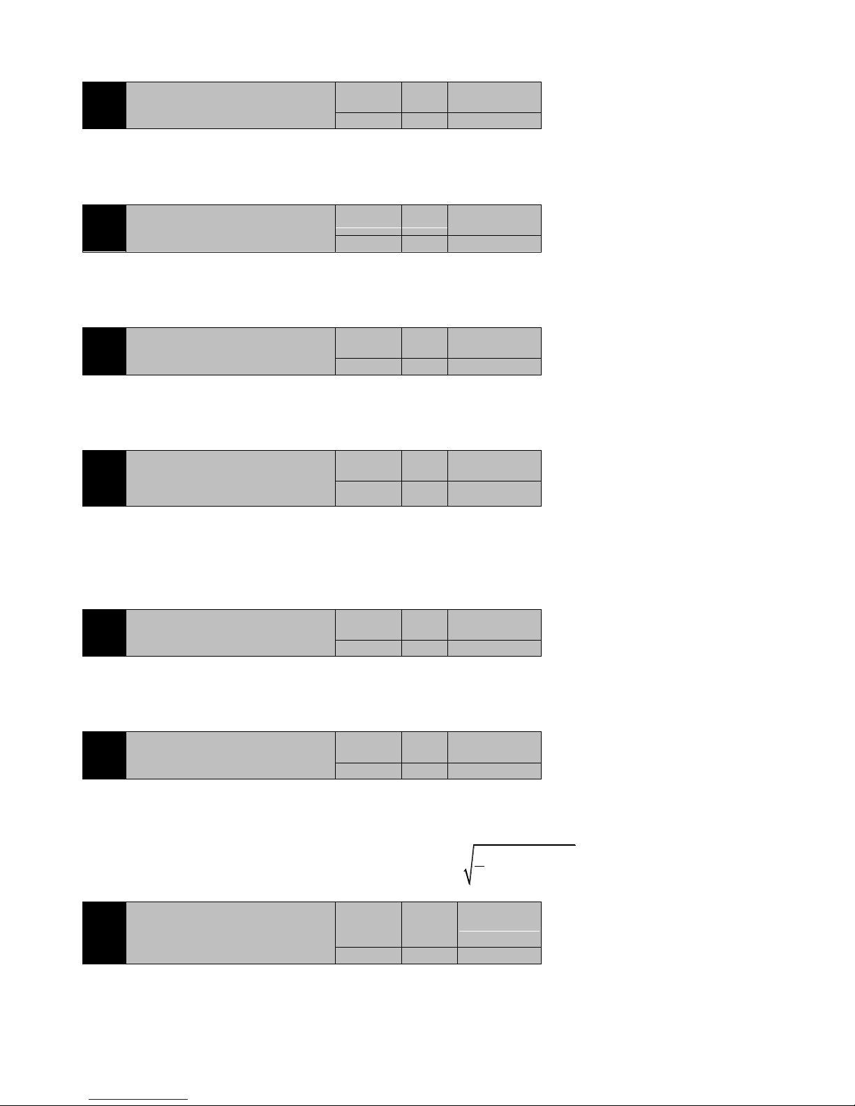
55
Display mode:Decimal system
Parameter function:Show multi circle value of encoder feedback, range: -32768~+32767
P0-06
Total running time
Initial value
Unit
Communication
Address
0
min
0006H
Control mode:P S T
Data size:32bit
Display mode:Decimal system
Parameter function:Display the total time elapsed after the servo drive is out of the factory.
P0-08
AI1 voltage value
Initial value
Unit
Communication
Address
0
mV
0008H
Control mode:P S T
Data size:16bit
Display mode:Decimal system
Parameter function: Display analog channel 1 acquisition of the actual value of the voltage.
P0-09
AI2 voltage value
Initial value
Unit
Communication
Address
0
mV
0009H
Control mode:P S T
Data size:16bit
Display mode:Decimal system
Parameter function:Display analog channel 2 acquisition of the actual value of the voltage.
P0-10
Encoder sector number (only for 2500ppr
incremental encoder)
Initial value
Unit
Communication
Address
0 - 000AH
Control mode:P S T
Data size:16bit
Display mode:Decimal system
Parameter function:Display the current incremental encoder sector number.
If the motor uses the 2500ppr incremental encoder, the sector number means the UVW combination of the encoder feedback, generally in the
counter clockwise rotation, jump in accordance with : 2- > 6- > 4- > 5- > 1- > 3-.
P0-11
Bus voltage
Initial value
Unit
Communication
Address
0 V 000BH
Control mode:P S T
Data size:16bit
Display mode:Decimal system
Parameter function: Show the actual value of the DC bus voltage in the drive.
P0-12
Effective current value
Initial value
Unit
Communication
Address
0 A 000CH
Control mode:P S T
Data size:16bit
Display mode:Decimal system
Parameter function:Show the effective value of current motor current.
Effective current value
2 2 2
2
()
3
U V W
I I I I
P0-13
Servo drive current state
Initial value
Unit
Communicatio
n
Address
- - 000DH
Control mode:P S T
Data size:16bit
Display mode: -
Parameter function:Show the current state of the servo drive.
When selecting the display P0-13, the following figure shows the display of the LED display on the servo drive panel.
Page 56
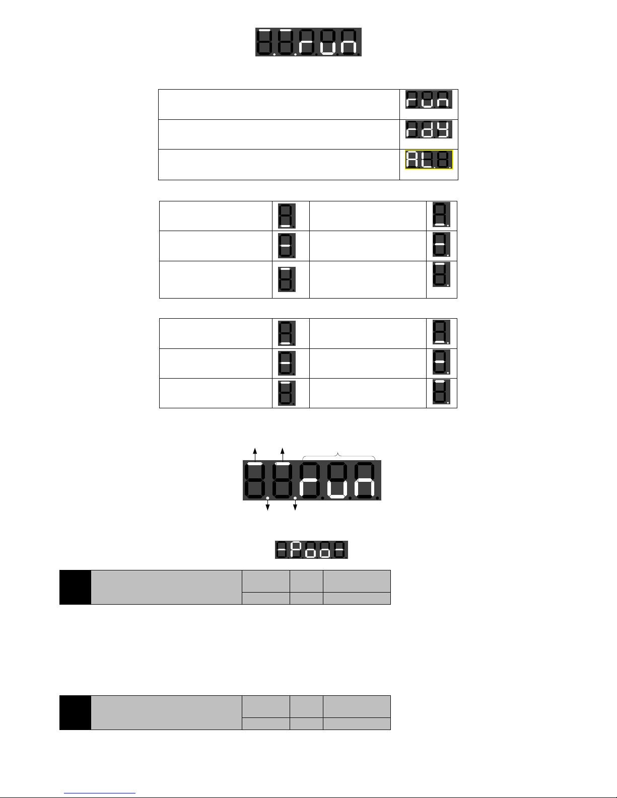
56
LED0LED1LED2LED3LED4
LED2, LED1,LED0 Show the current state of the servo drive,three states below:
Servo is in the normal operation condition,LED2~LED0 display:
Servo is ready but not enabled,LED2~LED0 display:
Servo is in a fault state,LED2~LED0 display:
LED3 shows current control mode for servo drives,the decimal point indicates whether the brake resistance is in the discharge state.
Servo is in position control
mode, the brake resistance is
not working
Servo is in the position control
mode, the brake resistance is
discharged.
Servo is in the speed control
mode, the brake resistance is
not working
Servo is in the speed control
mode, the brake resistor is
discharged
The servo is in the torque
control mode and the brake
resistance is not working
Servo is in the torque control
mode, the braking resistor is
discharged.
LED4 shows the direction of the current motor speed, the number of points to maintain the brake terminal (BK-) status.
Motor reversal, keeping the
brake control terminal BK is
invalid
Motor reversal, keeping the
brake control terminal BK
valid
Zero speed of motor, the
brake control terminal BK is
invalid
Zero speed of motor, the brake
control terminal BK is valid
The motor is rotating , and
the brake control terminal
BK is invalid
The motor is rotating , and the
brake control terminal BK is
valid
For example:
Motor
forward
Brake control
terminal valid
Braking resistor is
discharging
Torque
mode
Servo is in the
normal operation
condition.
In particular, when the servo is at the origin of the
regression process, P0-13is showing:
P0-14
Brake load ratio
Initial value
Unit
Communication
Address
0 % 000EH
Control mode:P S T
Data size:16bit
Display mode:Decimal system
Parameter function:When the motor is in the braking state, the load rate of the current braking resistor is displayed.
P0-15
IGBT module temperature
Initial value
Unit
Communication
Address
0 ℃ 000FH
Control mode:P S T
Data size:16bit
Page 57
57
Display mode:Decimal system
Parameter function: IGBT module inside temperature
EA100 servo driver has perfect over temperature protection mechanism. Because the temperature detection device is located inside the
IGBT module, the temperature can reach 100 or higher, which is a normal phenomenon.
P0-16
Total collected external pulse
Initial value
Unit
Communication
Address
0
ppr
0010H
Control mode:P S T
Data size:32bit
Display mode:Decimal system
Parameter function: In the position mode, the total number of pulses sent to the servo is useful only in the position control mode.
Note: This value may be more than five, please check the high data through the left shift key.
P0-18
Display P1-60 selected fault codes
Initial value
Unit
Communication
Address
0 - 0012H
Control mode:P S T
Data size:16bit
Display mode:Decimal system
Parameter function: Show the last fault (P1-60) of the fault code
P0-19
Show speed when P1-60 failure occurs
Initial value
Unit
Communication
Address
0
rpm
0013H
Control mode:P S T
Data size:16bit
Display mode:Decimal system
Parameter function: Show the motor speed when the last fault occurred.
P0-20
Show bus voltage when the P1-60 fault
occurs
Initial value
Unit
Communication
Address
0 V 0014H
Control mode:P S T
Data size:16bit
Display mode:Decimal system
Parameter function:Show bus voltage when the last fault occurs
P0-21
Show effective current when P1-60 fault
occurs
Initial value
Unit
Communication
Address
0 A 0015H
Control mode:P S T
Data size:16bit
Display mode:Decimal system
Parameter function:Show the effective value of the motor current at the time of the last fault.
P0-22
Show running time when P1-60 fault
occurs
Initial value
Unit
Communication
Address
0
min
0016H
Control mode:P S T
Data size:16bit
Display mode:Decimal system
Parameter function:Show the running time when the last fault occurs.
P0-24
Low 4 bit of encoder single-turn position
value (only for 17 bit encoder)
Initial value
Unit
Communication
Address
0
ppr
0018H
Control mode:P S T
Data size:16bit
Display mode:Decimal system
Parameter function:Show current single loop position value low 4 bits of 17 bit encoder feedback.
P0-25
High 5 bit encoder single-turn position
value (only for the 17 encoder)
Initial value
Unit
Communicatio
n
Address
0
ppr
0019H
Control mode:P S T
Page 58
58
Data size:16bit
Display mode:Decimal system
Parameter function:Show current single loop position value high 5bits of 17 bit encoder feedback.
Single loop position value =10000*P0-25+P0-24
For example:
P0-26
The current total inertia load - continuous
detection
Initial value
Unit
Communication
Address
0
kg*cm2
001AH
Control mode:P S
Data size:16bit
Display mode:Decimal system
Parameter function:Show identification of the total value of the load of the total inertia, when servo drive is online inertia identification.
Total load inertia = Motor inertia + Load inertia
P0-27
Current load inertia ratio - continuous
detection
Initial value
Unit
Communication
Address
0 % 001BH
Control mode:P S
Data size:16bit
Display mode:Decimal system
Parameter function:Show the ratio of the real time value of the load inertia and the inertia of the motor, when servo drive is online inertia
identification
P0-28
Total number of feedback pulses
Initial value
Unit
Communication
Address
0
ppr
001CH
Control mode:P
Data size:32bit
Display mode:Decimal system
Parameter function:Show the total number of the rotation of the servo motor ,it‘s useful only in the position control mode.
Note: This value may be more than five, please check the high data through the left shift key.
P0-30
Received external pulse frequency
Initial value
Unit
Communication
Address
0
KHz
001EH
Control mode:P
Data size:32bit
Display mode:Decimal system
Parameter function:Show the number of external pulses that are collected in the position adjustment cycle, it‘s only useful in the position
control mode.
7.2 P1-xx Basic control parameters
P1-00
Control mode selection
Initial value
Unit
Communication
Address
1
-
0100H
2100H
Control mode:P S T
Range:0~5
Data size:16bit
Display mode:Decimal system
Parameter function: Select control mode of servo system
P1-00=0:Speed control mode
Servo drive works in speed control mode, which can determine the speed of the motor running through communication, analog and multi
section speed.
P1-00=1:Position control mode
Servo drive works in position control mode, which can determine the position of the motor running through the external position pulse and
the multi section position.
P1-00=2:Torque control mode
Servo drive works in the torque control mode, which can determine the output torque of the motor through communication and analog.
P1-00=3:Speed- position switching mode
Servo drive works in speed -position switching mode , please set P1-00=3 and external DI
p i n fu n c t i o n c o d e se l e c t M S E L f u n c t i o n s. A t t h i s po i n t , se r v o d r i v e ca n s w i t c h be t w e e n
speed control mode and position control mode.
P0-24
P0-25
Single loop
position value =
10000*15+131=150131
00 131
00 015
Page 59
59
At the moment , make sure the instruction of speed and position to ensure
servo drive running correctly. During the switching between two kinds of control mode,
pay attention to switching can be running at zero speed state, but for safety,
switching control
mode when servo motor stop.From position control mode to speed control mode,
retentionpulse will be cleared.
If switch signals under the condition of higher than zero velocity rotational state,
even then velocity fall below zero speed ,also can‘t switch control mode.
Note: Although mode switching signal switch ON/OFF when zero signal is invalid,
then zero signal is valid ,it can’t switch control mode .
P1-00=4 : Torque-speed switching mode
Servo drive works in torque -speed switching mode , please set P1-00=4 and
external DI pin function code select MSEL functions.At this point , servo drive
can switch between torque control mode and speed control mode. Torque-speed
switching mode switch through external DI junction,whenever can switch
control mode,
Note: If instruction value of speed
instruction is 0 when switch speed control mode, the servo motor slowdown
in setting deceleration time to stop. If external DI signal unused MSELn
function, the drive can only run in torque control mode.
P1-00=5:Position-torque switching mode
Servo drive works in position-torque switching mode , please set P1-00=5 and
external DI pin function code select MSEL functions.At this point , servo drive
can switch between position control mode and torque control mode. It can
switch at zero speed state, but for safety, switching control mode when servo
motor stop. From position control mode to speed control mode, retentionpulse
will be cleared.
If switch signals under the condition of higher than zero velocity rotational
state, even then velocity fall below zero
speed ,also can‘t switch control mode.
NOTE: If external DI signal unused MSELn function, the drive can only run in
to position control mode.
P1-01
Position command source selection
Initial value
Unit
Communication
Address
0 - 2101H
Control mode:P
Range:0~1
Data size:16bit
Display mode:Decimal system
Parameter function:Select the source of the position command
P1-01=0:External pulse command (pt)
Position command is derived from the external input pulse number, the frequency of the external pulse determines the speed of the motor
running.
Please see the description of P1-02.
P1-01=1:Internal multiple command (pr)
Position command is derived from the internal multiple command set by the P2 group.
Please see the description of P1-03 and Section 7.3 .
P1-02
External pulse command input mode:
Initial value
Unit
Communication
Address
0 - 2102H
Control mode:P
Range:0~5
Data size:16bit
Display mode:Decimal system
Parameter function:The way of selecting an external pulse.
Table 7-1 pulse command logic
Parameters
Pulse form
Logic state
Direction of rotation
Forward
Reverse
P1-02=0
Pulse +
direction
Positive
logic
PULS
SIGN
P1-02=1
Pulse +
direction
Negative
logic
PULS
SIGN
Figure7-1 Speed-position switching mode
Speed control
mode
Position control
mode
Speed control
mode
Speed of
servo drive
motor
Zero
speed
Zero speed
signal
Mode
switch(MSEL)
(Note)
(Note)
Speed control
mode
Torque control
mode
Speed control
mode
Servo motor
speed
Switch mode
(MSEL)
Load torque
Forward torque
Torque
instruction
(Note)
Position control
mode
Torque control
mode
Position control
mode
Servo motor
rotate speed
Switch mode
(MSEL)
Torque
instruction
Zero speed
value
Zero speed
signal
Figure7-2 Torque-speed switching mode
Figure7-3Position-torque switching mode
Page 60
60
Parameters
Pulse form
Logic state
Direction of rotation
Forward
Reverse
P1-02=2
Two phase
orthogonal pulse
(4 times
frequency)
Positive
logic
PULS
SIGN
P1-02=3
Two phase
orthogonal pulse
(4 times
frequency)
Negative
logic
PULS
SIGN
P1-02=4
CCW/CW pulse
Positive
logic
PULS
SIGN
P1-02=5
CCW/CW pulse
Negative
logic
PULS
SIGN
P1-03
Internal position command multiple
execution options
Initial value
Unit
Communication
Address
0 - 2103H
0 - 2102H
Control mode:P
Range:0~2
Data size:16bit
Display mode:Decimal system
Parameter function:When the P2 group is given a position command, the multi section position switch mode is chosen.
P1-03=0:Press the 16 section position from the start of the PR1 cycle.
Pr1
Pr2 Pr3 Pr4 Pr5 Pr6
Pr8
Pr9
Pr10
Pr11
Pr12
Pr13
Pr14
Pr15
Pr16
Pr7
origin
P1-03=1:According to the 16 section position from the PR1 to the Pr16, running only one cycle .
Pr1
Pr2 Pr3 Pr4 Pr5 Pr6
Pr8
Pr9
Pr10
Pr11
Pr12
Pr13Pr14Pr15
Pr16
Pr7
origin
finish
P1-03=2:By external DI input switching operation as stipulated in the table 7-2. DI terminals must be set to 5(CMD0), 6(CMD1),
7(CMD2), 8(CMD3) and 9(CTRG)function.
DI default is low level effectively, if 4 road(5/6/7/8)DI input information in the following way to form a number D of bit 4:
CMD0CMD1CMD2CMD3
0
3
,and D for 0000-1111 respectively corresponding to pr1-pr16,according to the value of D run under different position
pr instructions.
CTRG
CMD3
CMD2
CMD1
CMD0
Pr1 Pr2 Pr3 Pr4 Pr5 Pr6 Pr7 Pr8 Pr9 Pr10Pr11 Pr12 Pr13Pr14 Pr15 Pr16 Pr1
NOTE:
1 : I t will n o t t a k e effe c t t h a t i f ch an g e s t h e cur r e n t p e r i od o f parame n ts i n t h e op e r a t i o n
when P1-03=0 or 1,these paraments will only be effective in the next run.
2 : T h e s e g m e n t h as i mp l emen t e d w i l l b e c l e a r e d t h a t i f c a n m a k e O F F o r p o w e r d o w n i n
t h e o p e r a t io n w h en P 1 -03 = 0 o r 1. A t th e mo m e n t , i f di r e c t l y t o r u n a g a i n , t h e c u r r e n t
position as a starting point ,since Pr1starts execution.
3 : T h e m u l t i s t a g e p o s i t i o n c o m m a n d e x e c u t i o n t r i g g e r e d b y f a l l i n g e d g e C T R G w h e n
P1-03=2,please set corresponding DI input terminal low level effectively.
4 : O n l y t h e e x e c u t i o n o f a p o s i t i o n c o m m a n d h a s f i n i s h e d , t h e r e s p o n s e t o a n o t h e r
command whenP1-03=2.
In the process of a position command execution, servo drive will not terminate the current position command execution by DI
terminal state change.
When the current position commad execution has finished, the servo drive in a wait state, according to the current DI terminal state
executes the corresponding segment of position instruction after receives the CTRG falling edge.
Table7-2internal position instruction multistage (DI)function
Pr
instruction
CMD3
CMD2
CMD1
CMD0
CTRG
Corresponding
paramter
explaination
Speed
setting
Pr1 0 0 0 0 ↓ P2-00
Pr1pulses total
P2-02
Page 61
61
Pr
instruction
CMD3
CMD2
CMD1
CMD0
CTRG
Corresponding
paramter
explaination
Speed
setting
P2-01
Pr2 0 0 0 1
↓
P2-04
P2-05
Pr2pulses total
P2-06
Pr3 0 0 1 0
↓
P2-08
P2-09
Pr3 pulses total
P2-10
Pr4 0 0 1 1
↓
P2-12
P2-13
Pr4 pulses total
P2-14
Pr5 0 1 0 0
↓
P2-16
P2-16
Pr5 pulses total
P2-18
Pr6 0 1 0 1
↓
P2-20
P2-21
Pr6 pulses total
P2-22
Pr7 0 1 1 0
↓
P2-24
P2-25
Pr7 pulses total
P2-26
Pr8 0 1 1 1
↓
P2-28
P2-29
Pr8 pulses total
P2-30
Pr9 1 0 0 0
↓
P2-32
P2-33
Pr9 pulses total
P2-34
Pr10 1 0 0 1
↓
P2-36
P2-37
Pr10 pulses
total
P2-38
Pr11 1 0 1 0
↓
P2-40
P2-41
Pr11 pulses
total
P2-42
Pr12 1 0 1 1
↓
P2-44
P2-45
Pr12 pulses
total
P2-46
Pr13 1 1 0 0
↓
P2-48
P2-49
Pr13 pulses
total
P2-50
Pr14 1 1 0 1
↓
P2-52
P2-53
Pr14 pulses
total
P2-54
Pr15 1 1 1 0
↓
P2-56
P2-57
Pr15 pulses
total
P2-58
Pr16 1 1 1 1
↓
P2-60
P2-61
Pr16 pulses
total
P2-62
NOTE: In the table, 0/1 is just respectively invalid/effective, doesn’t represent the actual
level. More are available at logic level settings.
P1-05
Speed command source selection
Initial value
Unit
Communication
Address
0 - 2105H
Control mode:S
Range:0~5
Data size:16bit
Display mode:Decimal system
Parameter function:Speed command source selection:
P1-05=0:Internal digital given (P3-00 given);
P1-05=1:Analog quantity 1 given (AI1);
P1-05=2:Analog quantity 2 given (AI2);
P1-05=3:Not used;
P1-05=4:Internal multi section speed command(P1-06);
P1-05=5:Point running (should make external JOG DI enable);
P1-06
Internal multi section speed command
execution mode
Initial value
Unit
Communication
Address
0 - 2106H
Control mode:S
Range:0~2
Data size:16bit
Display mode:Decimal system
Parameter function: When P1-05=4, select the switching mode of operation of multi section speed.
P1-06=0:According to the 16 section speed command from spd1 begin circularly run.
Spd1
Spd2 Spd3 Spd4 Spd5 Spd6
Spd8
Spd9
Spd10
Spd11
Spd12
Spd13
Spd14Spd15Spd16
Spd7
Starting
speed
P1-06=1:According to the 16 section speed command from the spd1 run to spd16, only run a cycle.
Spd1
Spd2 Spd3 Spd4 Spd5 Spd6
Spd8
Spd9
Spd10
Spd11
Spd12Spd13Spd14Spd15
Spd16
Spd7
Starting
speed
End
Page 62
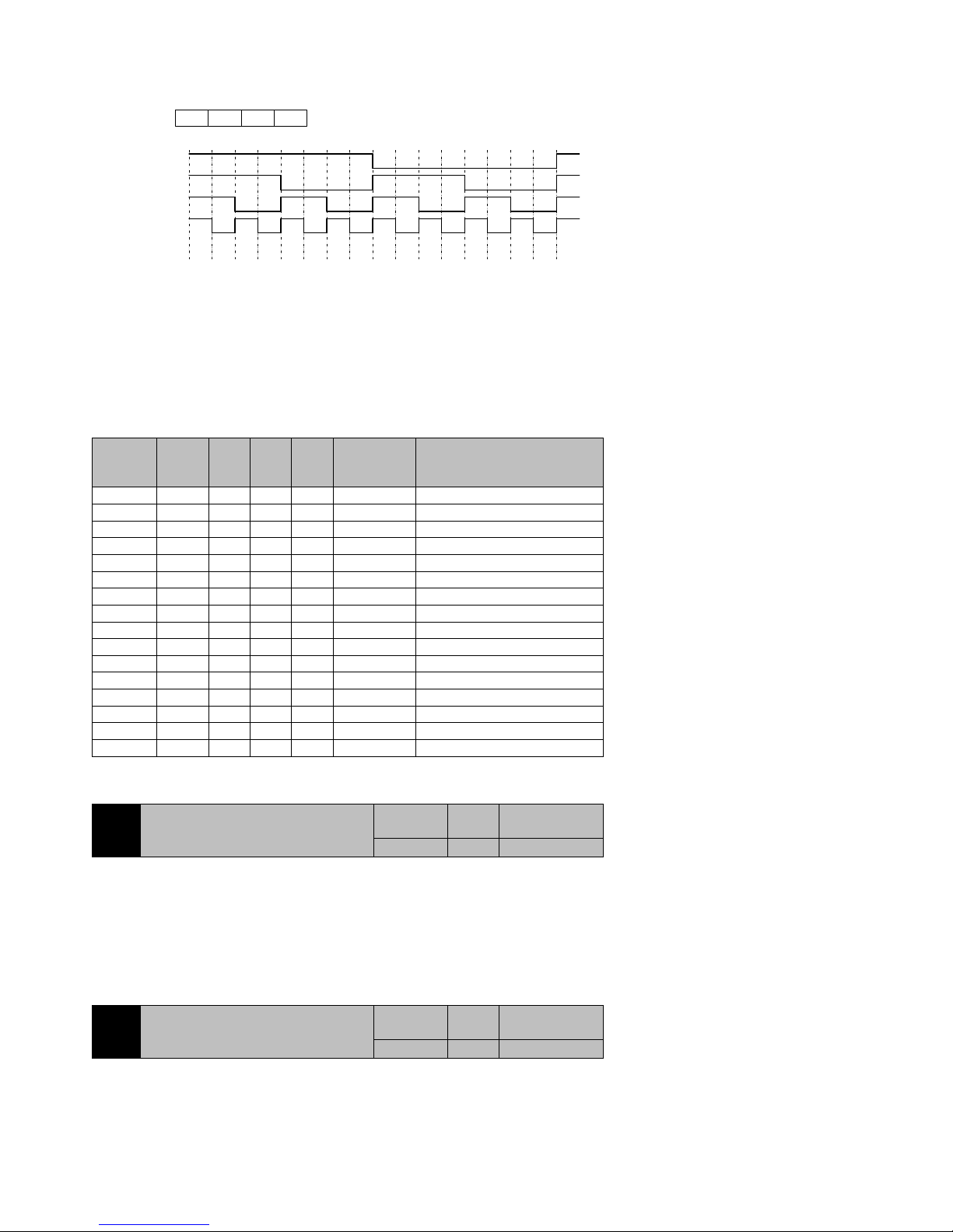
62
P1-06=2:External DI input switch operation by table 7-3. The DI terminal needs to set to 5 (CMD0), 6 (CMD1), 7 (CMD2) and 8 (CMD3)
function.
DI default is low level valid, if 4 input (5/6/7/8) DI form a 4bit number in the following ways:
D:
CMD0CMD1CMD2CMD3
0
3
, thenD is 0000-1111 corresponding to pr1-pr16, system according to the value of D running at different
speed command spd. As shown in the following diagram.
CMD3
CMD2
CMD1
CMD0
Spd
Spd1Spd2Spd3Spd4Spd5Spd6Spd7Spd8Spd9Spd10Spd11Spd12Spd13Spd14Spd15Spd16Spd
1
NOTE:
1:It will not take effect that if modifies the current segment paraments in the operation when
P1-06=0 or1.
2 : T h e s e g m e n t h as i mp l emen t e d w i l l b e c l e a r e d t h a t i f c a n m a k e O F F o r p o w e r d o w n i n
the operation when P1-06=0 or 1.At the moment , if directly to run again, since Spd1 starts
execution.
3 : I f DI t e r m i n a l st at e u n c h a n g e d , s er vo d r i v e r u n co n t i n u o u s l y a c c o r d i n g t o t h e curr en t D I
t e r mi n a l s t a t e c o r r e s p o n d i n g sp e e d whenP1 - 0 6 = 2.On c e t h e D I t e r m inal s t a t e cha n g e s , t hen
i m m e d i a t e l y r u n t o t h e s p e e d o f n e w D I t e r m i n a l s t a te a c c o rd i n g t o ac c e l e ra t i o n an d
deceleration time.
Table7-3 Internal multistage speed instruction(DI)function
Internal
speed
instruction
CMD3
CMD2
CMD1
CMD0
Corresponding
paramter
Explaination
Spd1 0 0 0 0
P3-00
Setting speed (0-±motor rated speed)
Spd2 0 0 0 1
P3-02
Setting speed (0-±motor rated speed)
Spd3 0 0 1 0
P3-04
Setting speed (0-±motor rated speed)
Spd4 0 0 1 1
P3-06
Setting speed (0-±motor rated speed)
Spd5 0 1 0 0
P3-08
Setting speed (0-±motor rated speed)
Spd6 0 1 0 1
P3-10
Setting speed (0-±motor rated speed)
Spd7 0 1 1 0
P3-12
Setting speed (0-±motor rated speed)
Spd8 0 1 1 1
P3-14
Setting speed (0-±motor rated speed)
Spd9 1 0 0 0
P3-16
Setting speed (0-±motor rated speed)
Spd10
1 0 0 1 P3-18
Setting speed (0-±motor rated speed)
Spd11
1 0 1 0 P3-20
Setting speed (0-±motor rated speed)
Spd12
1 0 1 1 P3-22
Setting speed (0-±motor rated speed)
Spd13
1 1 0 0 P3-24
Setting speed (0-±motor rated speed)
Spd14
1 1 0 1 P3-26
Setting speed (0-±motor rated speed)
Spd15
1 1 1 0 P3-28
Setting speed (0-±motor rated speed)
Spd16
1 1 1 1 P3-30
Setting speed (0-±motor rated speed)
NOTE: In the table, 0/1 is just respectively invalid/effective, doesn’t represent the actual
level. More are available at logic level settings.
P1-07
Frequency dividing output
Initial value
Unit
Communication
Address
2500
ppr
2107H
Control mode:P S T
Range:When using 2500ppr encoder:358~2500;When using 17bit encoder:1171~4095
Data size:16bit
Display mode:Decimal system
Parameter function:Servo motor rotation one circle, drive feedback A, B pulse number to the host computer.
For example, P1-07=550, then servo motor rotation one circle, PA+-、PB+- terminals output 550 pulse, the orthogonal relationship between
PA+- pulse and PB+- pulse.
Do not set the value beyond the above range, otherwise the output pulse will be incorrect.
P1-08
Torque command selection
Initial value
Unit
Communication
Address
0 - 2108H
Control mode:T
Range:0~2
Data size:16bit
Display mode:Decimal system
Parameter function: Select the source of the torque command on torque control mode
P1-08=0:Internal digital given (P4-00 given);
Page 63
63
P1-08=1:Analog value 1 given (AI1);
P1-08=2:Analog value 2 given (AI2);
P1-09
Speed feedback filter time constant
Initial value
Unit
Communication
Address
500 s 2109H
Control mode:P S T
Range:0~2000
Data size:16bit
Display mode:Decimal system
Parameter function:Setting speed feedback filter time constant.
The greater the parameter value, detection more smooth, but the speed of bandwidth becomes smaller; the parameter value is smaller, faster
response speed detection, greater bandwidth. But the parameters are too small to cause noise, too big to be a shock.
P1-10
First group of resonance frequency setting
value
Initial value
Unit
Communication
Address
1000
Hz
210AH
Control mode:P S
Range:50~1000
Data size:16bit
Display mode:Decimal system
Parameter function:Please see the function of P1-50 parameters.
P1-11
First group of resonance points in the
notch depth
Initail value
Unit
Communication
Address
0
dB
210BH
Control mode:P S
Range:0~32
Data size:16bit
Display mode:Decimal system
Parameter function:Please see the function of P1-50 parameters.
P1-12
Internal position command acceleration
time T
PACC
Initail value
Unit
Communication
Address
100
ms
210CH
P1-13
Internal position command deceleration
time T
PDEC
Initail value
Unit
Communication
Address
100
ms
210DH
P1-14
Internal position command S curve
smoothing time TPL
Initail value
Unit
Communication
Address
10
ms
210EH
Control mode:P
Range:P1-12, P1-13: 0~10000. P1-14: 0~1000
Data size:16bit
Display mode:Decimal system
Parameter function:When executes internal multistage position instruction(P1-01=1),the three parameters are used to set acceleration an
deceleration time of motor. The three parameters are invalid when executes position instruction of external pulse.
P1-12: Set the motor speed acceleration time from 0 to motor rated speed.
P1-13: Set the motor speed deceleration time from motor rated speed to 0.
P1-14:Set the smoothing time of S curve in the process of acceleration and deceleration.
Page 64
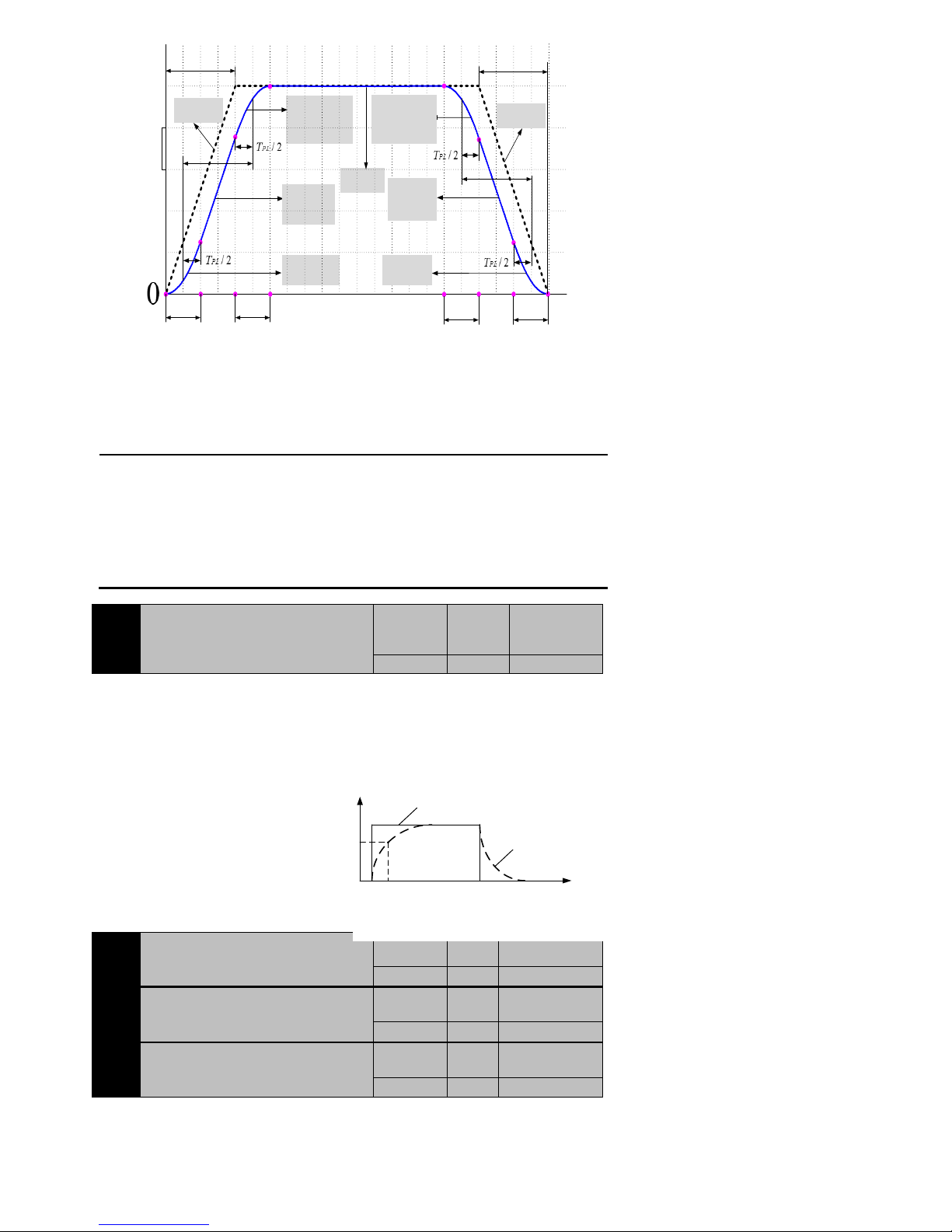
64
S curve
acceleration
peroid
S curve
uniform
acceleration
peroid
S curve
deceleration and
acceleration
peroid
Uniform
peroid
Motor
rated
speed
T
PACC
t
1
t
3
t
2
T
PL
T
PL
T
PACC
Linear
acceleration
t
4
t
6
t
5
T
PL
T
PL
T
PDEC
T
PDEC
S curve
deceleration
peroid
S curve
uniform
deceleration
peroid
S curve
acceleration and
deceleration
peroid
Linear
deceleration
Figure7-4 Internal position instruction acceleration and deceleration time、S curve smoth
In the figure, linear acceleration is acceleration and deceleration curve of motor when P1-14=0.
When P1-14 isn‘t 0,motor accelerates and decelerates according to S curve amongTPL(P1-14).From 0 speed to motor rated speed required
total acceleration time is T
PACC+TPL
,from motor rated speed to 0 speed required total deceleration time is T
PDEC+TPL
。
The purpose of S curve is making movement instruction to carry on the smoothing processing, avoiding system produces too much quick
jump(differential of acceleration) because of drastic change of input instruction, thus stimulates vibration and noise of the mechanical
structure.
NOTE:
P1-12、P1-13 refers to the variation of motor speed is motor rated speed requiring
acceleration and deceleration time. If the variation of target speed isn’t motor rated
speed, the required time changes according to the proportion of variation of target
speed and motor rated speed.
For example, motor target speed is 1500rpm, motor rated speed is 3000rpm,
P1-12=200ms,P1-13=300ms,motor speed acceleration time is 100ms from 0 to
1500rpm,motor speed deceleration time is 150ms from 1500rpm to 0.
P1-15
External pulse command smoothing filter
time constant
Initail value
Unit
Communicatio
n
Address
0
ms
210FH
Control mode:P
Range:0~30000
Data size:16bit
Display mode:Decimal system
Parameter function:The time constant for external pulse signal to smooth filtering .when set
0 ,it‘s invalid.
The function of parameter is making input pulse instruction smoothing, but will be
delay phenomenon. Commonly used in :
accelerate and deceleration;
PC haven‘t the function of
Electronic gear is large;
low;
Instruction frequency is
jump、unstable phenomenon and so on when It occurs to advanced step
motor runs.
P1-16
Speed command acceleration timeT
SACC
Initail value
Unit
Communication
Address
200
ms
2110H
P1-17
Speed command deceleration time T
SDEC
Initail value
Unit
Communication
Address
200
ms
2111H
P1-18
Speed command S curve smoothing time
TSL
Initail value
Unit
Communication
Address
50
ms
2112H
Control mode:S
Range:P1-16、P1-17 为 0~30000,P1-18 为 0~2000
Data size:16bit
Display mode:Decimal system
Pulse
instruction
frequency
Before the
filtering
After the
filtering
0 t
63.2%
P1-15
Figure7-5 External pulse command smoothing
filter time constant
Page 65

65
Parameter function:When the drive is a given model of internal speed(P1-05=0、4、5),the three parameters are used in setting the acceleration
and deceleration time of motor.
P1-16: Set the motor speed acceleration time from 0 to motor rated speed.
P1-17: Set the motor speed deceleration time from motor rated speed to 0.
P1-18:Set the smoothing time of S curve in the process of acceleration and deceleration.
In the process of accelerate or decelerate, if use S curve(P1-18≠0),the drive adopts three stage acceleration curve planning to dispose
m o v e m e n t i n s t r u c t i o n s m o o t h l y . A t t h e m o m e n t ,
the acceleration is continuous, avoiding system produces too much quick jump(differential of
acceleration) because of drastic change of input instruction, thus stimulates vibration and
noise of the mechanical structure. Users can use P1-16 adjusting the slope of speed‘s change
in the accelerated process; Use the P1-17 adjusting the slope of speed‘s change in the
decelerated process; Use P1 to 18 to improve the steady state of motor start a
S curve
acceleration
peroid
S curve
uniform
acceleration
peroid
S curve
deceleration
and
acceleration
peroid
Uniform
peroid
Motor
rated
speed
T
SACC
t
1
t
3
t
2
T
SL
T
SL
T
SACC
Linear
acceleration
t
4
t
6
t
5
T
SL
T
SL
T
SDEC
T
SDEC
S curve
deceleration
peroid
S curve
uniform
deceleration
peroid
S curve
acceleration
and
deceleration
peroid
Linear
deceleration
Figure7-6 Speed instruction acceleration and deceleration time ,S curve
NOTE:
P1-16, P1-17 refers to the variation of motor speed is motor rated speed requiring
acceleration and deceleration time. If the variation of target speed isn’t motor rated
speed, the required time changes according to the proportion of variation of target
speed and motor rated speed.
For example, motor target speed is 1500rpm, motor rated speed is 3000rpm,
P1-16=200ms, P1-17=300ms, motor speed acceleration time is 100ms from 0 to
1500rpm,motor speed deceleration time is 150ms from 1500rpm to 0.
P1-19
Speed command low-pass filter smoothing
filter time constant
Initail value
Unit
Communication
Address
10.0
ms
2113H
Control mode:S
Range:0.0~1000.0
Data size:16bit
Display mode:Decimal system
Parameter function:About speed instruction after S curve for low pass filter, make the speed instruction more smoothly. Usually just use one
of the S curve or low pass filter. Two kinds of use can make the system response slow.
Internal
inching
External DI
inching
Speed
smooth of
S
First order
low pass
filtering
smoothing
-
+
P1-16
P1-17
P1-18
P1-19
Speed given module
Internal
multistage
speed
The external
analog given
Velocity
deviation
Position regulator
input given speed
Speed
feedback
Figure7-7Speed command transmionroute
P1-20
Analog speed command gain
Initail value
Unit
Communication
Address
Rated speed of
the motor
rpm
2114H
Control mode:S
Range:0~Rated speed of the motor
Data size:16bit
Display mode:Decimal system
Parameter function:Analog speed command gain setting is used to set corresponding motor speed when external analog value is 10 V through
Page 66
66
external voltage give speed(P1-05=1、2 or 3).
For example:
W h e n P 1 - 2 0 = 1 0 0 0 , e x t er n a l a n a l o g v a l u e = 1 0 V , t h e mo t o r r u n n i n g s p e e d = 1 0 0 0 r p m ;
W h e n P 1 - 2 0 = 5 0 0 , e x t e r n a l a n a l o g v a l u e = 1 0 V , t h e m o t o r r u n n i n g s p e e d = 5 0 0 r p m .
0
10
Analog
voltage/V
Speed/rp
m
P1-20=1000
P1-20=500
P1-20=1500
1500
1000
500
Figure7-8 Analog speed command gain
P1-21
Current feedback low-pass smoothing
constant
Initail value
Unit
Communication
Address
100 s 2115H
Control mode:P S T
Range:0~10000
Data size:16bit
Display mode:Decimal system
Parameter function:More are available at P1-50Parameter function
P1-22
Torque command low-pass smoothing
constant
Initail value
Unit
Communication
Address
100 s 2116H
Control Mode:P S T
Range:0~10000
Data size:16bit
Display mode:Decimal system
Parameter function:More are available at P1-50Parameter function
P1-23
The torque command when analog
maximum input (10V)
Initail value
Unit
Communicatio
n
Address
100 2117H
Control Mode:T
Range:0~300
Data size:16bit
Display mode:Decimal system
Parameter function:Analog torque command gain setting is used when external voltage give torque(Set P1-08 to 1, 2 or 3).Setting the
corresponding torque when external value is 10V, the size of value indicates the percentage of the relative motor rated torque.
For example: When P1-23=100,external given=10V,motor runs with rated torque; when external give to 5V,motor runs with50% rated torque.
P1-24
Second group of resonance frequency setting
value
Initail
value
Unit
Communication
Address
1000 z 2118H
Control Mode:P S
Range:50~1000
Data size:16bit
Display mode:Decimal system
Parameter function:More are available at P1-50 Parameter function
P1-25
Second group of resonance points in the notch depth
Initail
value
Unit
Communication
Address
0
dB
2119H
Control Mode:P S
Range:0~32
Data size:16bit
Display mode:Decimal system
Parameter function:More are available at P1-50Parameter function
P1-26
Electronic gear ratio factor
Initail value
Unit
Communication
Address
0 - 211AH
Control Mode:P
Range:0~17
Data size:16bit
Display mode:Decimal system
Parameter function:The default is 0 when using 2500ppr encoder,the default is 17 when using 17 bit encoder .The meaning refers to the
Page 67
67
interpretation of the electronic gear.
P1-27
Electronic gear numerator 1
Initail value
Unit
Communication
Address
1 - 211BH
P1-28
Electronic gear denominator
Initail value
Unit
Communication
Address
1 - 211CH
P1-29
Electronic gear numerator 2
Initail value
Unit
Communication
Address
1 - 211DH
P1-30
Electronic gear numerator 3
Initail value
Unit
Communication
Address
1 - 211EH
P1-31
Electronic gear numerator 4
Initail value
Unit
Communication
Address
1 - 211FH
Control Mode:P
Range:1~65535
Data size:16bit
Display mode:Decimal system
Parameter function: P1-26~P1-31used to set electronic gear ratio.
Electronic gear ratio
It can be easily match with all kinds of pulse source through setting electronic gear ratio under position control mode, in order to achieve the
ideal control resolution ( the Angle/pulse).
Electronic gear ratio set way:
① Set electronic gear ratio factor P1-26。
Set electronic gear ratio factor mainly depend on the type of the encoder motor used.
The parameter must be 0 when motor used 2500ppr incremental encoder.
The parameter must be 17 when motor used17bit encoder, it shows that 131072 pulse encoder feedback in per circle. Also set
another nonzero value, it depends on the calculation results of electronic gear ratio.
② Calculate the desirable electronic gear ratio
G:Electronic gear ratio;
P:The number of input instructions‘ pulse;
N:Motor rotation laps;
C:The encoder line number, if encoder is 2500ppr incremental, then C=10000(After four times the frequency )
If encoder is 17bit encoder, then C=131072.
③ It needn’t get a specific number about calculation of electronic gear ratio G, just make numerator and denominator divided by
common divisor, the value of numerator and denominator can meet parameter Range as far as possible.
For example:
Case1:motor uses 2500ppr encoder,when input instruction is 6000 pulses,servo motor rotate one circle:
Because of 2500ppr encoder,P1-26 must be 0. Electronic gear numerator and denominator can be set:
Setting way I:P1-27=100,P1-28=60
Setting way II:P1-27=10,P1-28=6
Setting way III:P1-27=5,P1-28=3
Case2:motor uses 17bit encoder, when input instruction is 5600 pulses, servo motor rotate one circle:
17 16 15
1 131072 1 2 1
= = =
5600 5600 5600 1400
2 2 2
NC
G
P
The parameters can be set:
Setting way I:P1-26=17,P1-27=1,P1-28=5600
Setting way II:P1-26=16,P1-27=2,P1-28=5600
Setting way III:P1-26=15,P1-27=1,P1-28=1400
④ Electronic gear ratio for the recommended range(when uses 2500ppr encoder)
1
1000
1000
G
⑤ When it need switching frequently among the different electronic gear ratio, it can modify P1-27、P1-28 by communication mode
online; also can by setting two DI terminals for 20 (GNUM0) and 21 (GNUM1) function, then to switch through external DI input. at this
time, the corresponding electronic gear numerator as shown below:
GNUM0
GNUM1
Effective electronic gear
numerator
0 0 P1-27
0 1 P1-29
1 0 P1-30
1 1 P1-31
Page 68
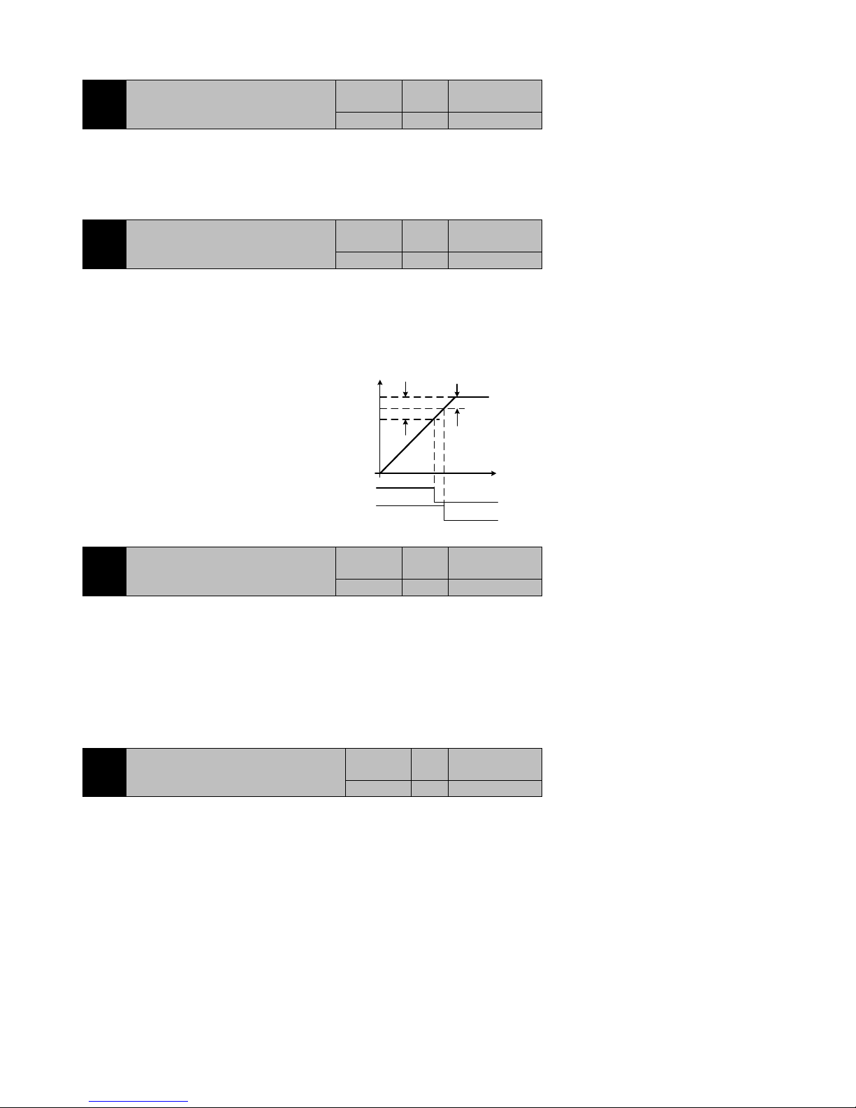
68
⑥ Due to the electronic gear denominator P1-28 is a fixed value, so if you need to use the external terminal switching electronic gear
ratio, please select the appropriate denominator values of electronic gear carefully.
P1-32
Positioning closed width
Initail value
Unit
Communication
Address
20
ppr
2120H
Control Mode:P
Range:1~65535
Data size:16bit
Display mode:Decimal system
Parameter function: More are available at P1-33Parameter function
P1-33
Positioning completed width
Initail value
Unit
Communication
Address
10
ppr
2121H
Control Mode:P
Range:0~65535
Data size:16bit
Display mode:Decimal system
Parameter function: The setting of positioning closed and completed standard, when counting deviation is less than the set value, the
corresponding event has occurred. If there is DO terminal at this point has been set for 5 function (positioning close /PNEAR+-) and 6
(positioning complete/COIN+-), the corresponding DO output terminal would be effective. Please see below.
Figure7-8 Positioning closed and completed width
P1-34
Position deviation clear external DI
signal action choice
Initail value
Unit
Communication
Address
0 - 2122H
Control Mode:P
Range:0~3
Data size:16bit
Display mode:Decimal system
Parameter function:Clearing deviation by choose any external DI signal.
P1-34=0:Clearing by P-CLR rising edge
P1-34=1:Clearing by P-CLR low level
P1-34=2:Clearing by P-CLR high level
P1-34=3:Clearing by P-CLR falling edge
P1-35
Position deviation automatic clear choice
Initail
value
Unit
Communication
Address
0 - 2123H
Control Mode:P
Range:0~2
Data size:16bit
Display mode:Decimal system
Parameter function: choose the way of position deviation clearing
P1-35=0:Only automatic removal of deviation when fault happens;
P1-35=1:Automatic removal of deviation when fault happens and servo drive OFF;
P1-35=2:Does not automatic removal of deviation, adopt P1-34 way to clear;
Pulses
Destination
time/s
/PNEAR+-
P1-32
P1-33
/COIN+-
Low level
effectively
Low level
effectively
Page 69
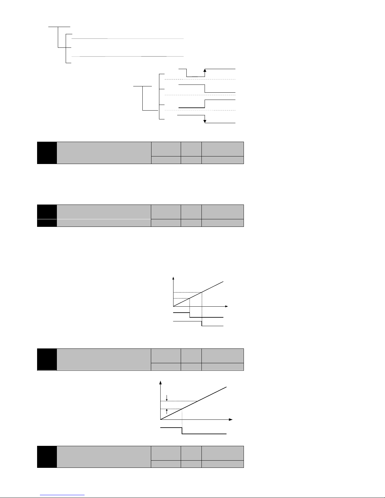
69
When fault happens, it will automatic removal of deviation.
But only to clear the fault source, not to clear fault warning.
Automatic removal of deviation when fault happens and servo drive
OFF .The former is to eliminate the fault source, the latter is to avoid
servo OFF. There is warning when external given haven’t cancelde.
Does not automatic removal of deviation, adopt P1-34
way to clear. It need defining a DI terminal for 3
functions (P - the CLR)
Rising edge
clearing
Low level
clearing
High level
clearing
Falling level
clearing
P1-35
0
2
1
0
3
2
1
P1-34
NOTE:P1-34 definition has been effective, when
P1-35=0 or 1, it is still cleared through setting no.3 function(P-CLR)DI terminal.
P1-36
Position follow deviation alarm
threshold
Initail value
Unit
Communication
Address
25000
*256ppr
2124H
Control Mode:P
Range:0~65535
Data size:16bit
Display mode:Decimal system
Parameter function:Setting position follow deviation alarm threshold, more are available at P1-37Parameter function.
P1-37
Position follow deviation fault threshold
Initail value
Unit
Communication
Address
25000
*256ppr
2125H
Control Mode:P
Range:0~65535
Data size:16bit
Display mode:Decimal system
Parameter function:Setting position follow deviation fault threshold.
When position deviation corresponds the set, output respectively alarm and fault signal to response events.
Alarm signal
Fault signal
high level
effective
Low level
effective
P1-36
P1-37
position
deviation
puls
Figure7-9 Position followdeviation alarm and fault threshold
NOTE:When P1-36=0 and P1-37=0, position follow deviation alarm and fault will be blocked.
P1-38
Torque reaches threshold value
Initail value
Unit
Communication
Address
0
%
2126H
Control Mode:T
Range:0~10.0
Data size:16bit
Display mode:Decimal system
Parameter function:
When |setting torque—actual torque|≤
P1-38, torque to events. If a DO terminal is
defined as no.13 function (/ Tcmp) at this time, then the terminal output signal
effectively.
Figure7-10 Torque reaches threshold
P1-39
The highest speed setting
Initail value
Unit
Communication
Address
5000
rpm
2127H
Control Mode:P S T
/Tcmp
Low level
effective
P1-38
Given torque
torque/%
time/S
Actual
torque
Page 70
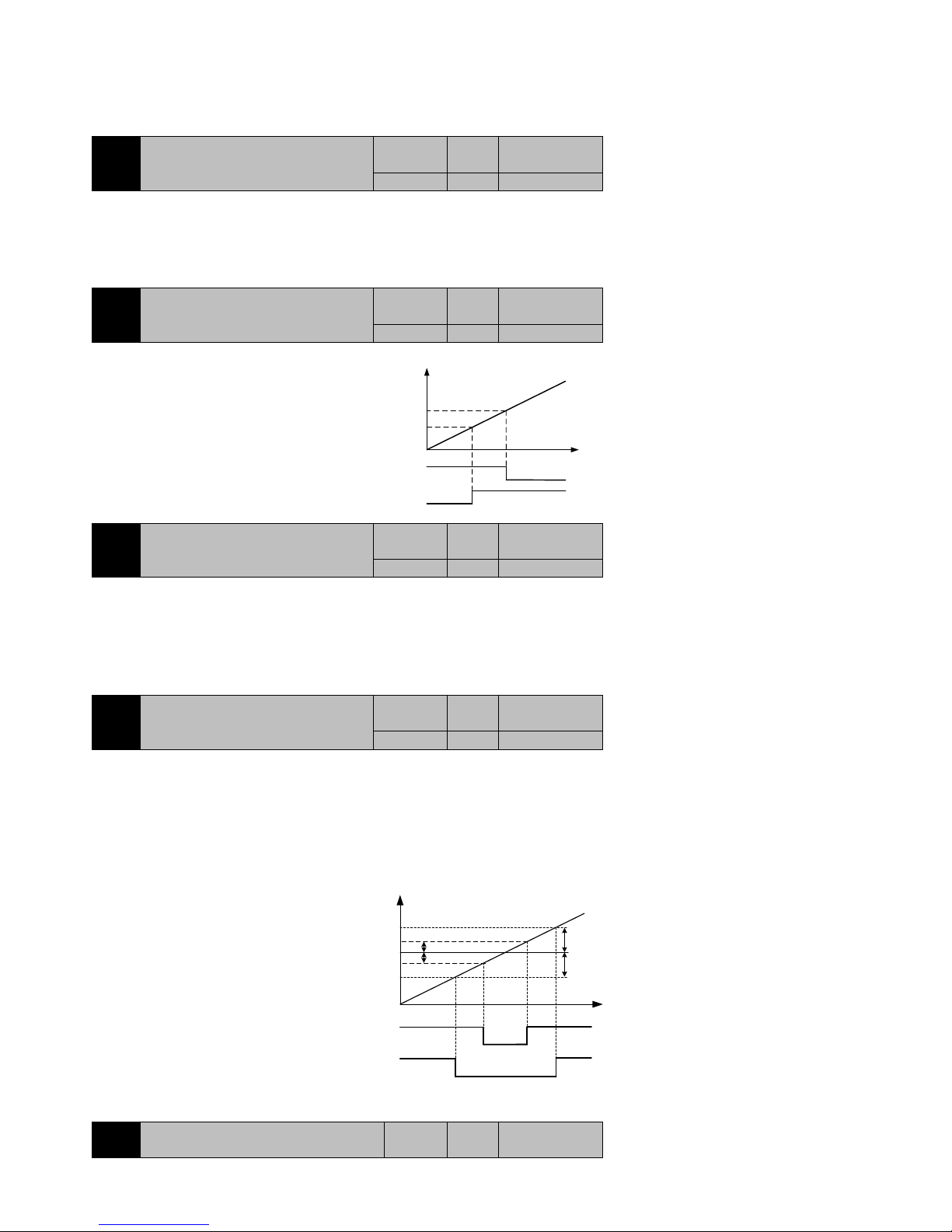
70
Range:0~the motor highest speed
Data size:16bit
Display mode:Decimal system
Parameter function:Setting the highest speed allowed. The given value of system shall not be higher than the set, if the motor running speed is
higher than this value, speeding fault happens.
P1-40
Zero speed signal output
Initail value
Unit
Communication
Address
10
rpm
2128H
Control Mode:P S T
Range:10~100
Data size:16bit
Display mode:Decimal system
Parameter function:More are available at P1-41Parameter function.
P1-41
Rotation signal output value
Initail value
Unit
Communication
Address
10
rpm
2129H
Control Mode:P S T
Range:10~1000
Data size:16bit
Display mode:Decimal system
Parameter function:When motor stops and the
motor speed is less than P1-40, it argues that
the motor has stopped turning. If the motor speed is higher than P1-41, it argues that the motor
function(Zero speed signal/ZER0+-);no.5
in rotating condition. If set any DO terminal no.4
function(Motor rotation signal/TGON+-),will
output a corresponding signal.
Figure7-11 Zero speed and
rotation signal output value
P1-42
Speed approaches threshold
Initail value
Unit
Communication
Address
100
rpm
212AH
Control Mode:P S T
Range:10~3000
Data size:16bit
Display mode:Decimal system
Parameter function:When |given speed-current speed|≤P1-42,it‘s closed to the set speed .If any DO terminal is set no.5 function(speed
approaches/V-CLS+-), the terminal output effective, as shown in figure7-12.
P1-43
Speed reaches threshold
Initail value
Unit
Communication
Address
20
rpm
212BH
Control Mode:S
Range:1~3000
Data size:16bit
Display mode:Decimal system
Parameter function:
When | given speed-current speed |≤P1-43, it reaches the set speed. If any DO terminal is set no.6 function(speed reaches/ V-CMP+-), the
terminal output effective.
/V-CMP+-
effective
Given speed
speed/rpm
Actual speed
effective
/V-CLS+-
Actual speed
P1-43
P1-42
Actual speed
Actual speed
P1-43
P1-42
Figure7-12 speed approaches and reaches threshold
P1-44
Simulation speed instruction zero fixed
value
Initail
value
Unit
Communication
Address
/TGON+-
Low level
effective
P1-41
speed/rpm
time/S
P1-40
Low level
effective
/ZERO+-
Page 71
71
10
rpm
212CH
Control Mode:S
Range:0~300
Data size:16bit
Display mode:Decimal system
Parameter function:Simulation speed instruction zero fixed value setting is namely zero clamp.
When servo drive chooses speed mode and speed instruction given by external analog value, the analog voltage is 0, because of external
electromagnetic interference or zero drift and so on, can lead to motor can't rest. If need external analog input voltage near 0 V, the motor
must be stationary, then you can use this function.
When this function is adopted to meet the following two conditions:
The absolute value of the speed instruction that input analog voltage corresponding is less than P1-44;
The drive is defined as DI terminal of zero fixed signal ZCLAMP is effective.
When the above conditions are satisfied, servo drive switch from the speed mode to position mode automatically, make the motor in the
position to lock within ±1 pulse. Even under the action of external force, also returns zero clamp position.
NOTE:When use 2500ppr encoder, it‘s ±1pulse,When use 17bit encoder, it‘s ±3pulse.
P1-45
Z pulse input width
Initail value
Unit
Communication
Address
0
0.5ms
212DH
Control Mode:P S T
Range:0~3
Data size:16bit
Display mode:Decimal system
Parameter function:Broadening of Z pulse. when PC can‘t capture a narrow Z pulse, then can broaden it.
Because the width of Z pulse will decrease with motor speed increase, for the convenience of matching with all kinds of PC, Z pulse width can
be adjusted according to actual situation. It set to 0 represents the output of Z pulse is original width of encoder Z signal.
Z pulse
P1-45
EXTZ
Z Pulse
broadening
P1-46
Forward the maximum torque limit
Initail value
Unit
Communication
Address
300.0
%
212EH
Control Mode:P S T
Range:0.0~350.0
Data size:16bit
Display mode:Decimal system
Parameter function:When P1-48=0, set forward direction, the limiting value of the motor output torque. The rated torque of the motor is
benchmark.
P1-47
Inversion the maximum torque limit
Initail value
Unit
Communication
Address
300.0
%
212FH
Control Mode:P S T
Range:0.0~350.0
Data size:16bit
Display mode:Decimal system
Parameter function:When P1-48=0, set inversion direction, the limiting value of the motor output torque. The rated torque of the motor is
benchmark.
P1-48
Torque limit source selection
Initail value
Unit
Communication
Address
0
-
2130H
Control Mode:P S T
Range:0~3
Data size:16bit
Display mode:Decimal system
Parameter function:Choosing the source of the motor output torque is limited.
P1-48=0:internal limit P1-46、P1-47 ;
P1-48=1: analog value1 limit,would be limited by P1-46、P1-47 at the same time;
P1-48=2: analog value2 limit,would be limited by P1-46、P1-47 at the same time;
P1-48=3:hold;
The meaning of the torque limit shown as follow
Page 72
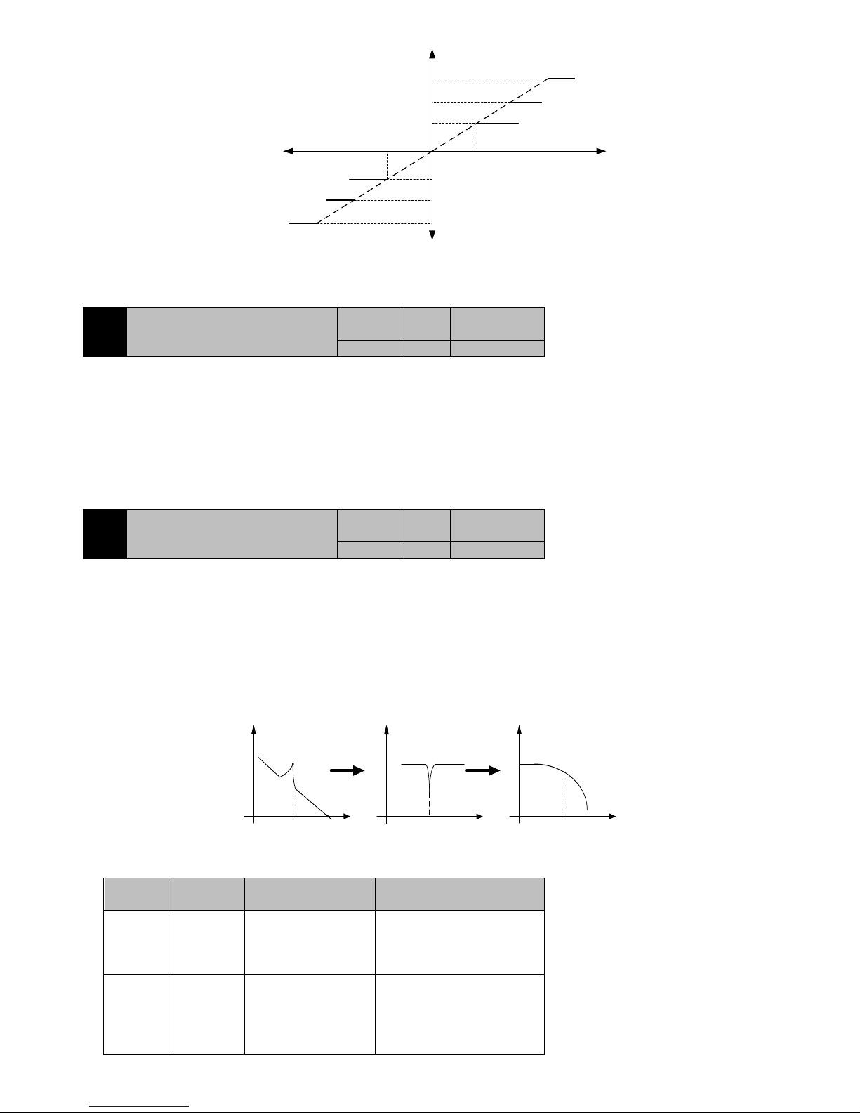
72
P1-46
torque/%
voltage/V
AI1
Given positive
torque
Given negative
torque
P1-47
AI1
Torque instruction given
by internal number.
P1-48=0
The value of AT1 is
greater than torque
output of P1-47
The value of AT1 is
less than torque output
of P1-47
The absolute value of AT1
is greater than torque
output of P1-47
The absolute value of AT1
is less than torque output of
P1-47
Figure7-13 torque limit
It can limit torque and speed by external instruction, please refers to specification of P4-01.
P1-49
The third group of resonance frequency
value
Initail value
Unit
Communication
Address
1000
Hz
2131H
Control Mode:P S
Range:50~1000
Data size:16bit
Display mode:Decimal system
Control Mode:P S
Range:50~1000
Data size:16bit
Display mode:Decimal system
Parameter function:More are available at P1-50Parameter function
P1-50
The third group of notch depth of
resonance point
Initail value
Unit
Communication
Address
0
dB
2132H
Control Mode:P S
Range:0~32
Data size:16bit
Display mode:Decimal system
Parameter function:
If the mechanical system resonance occurs, it may because of large rigidity, rapid response servo system, reduce the gain may improve, but
will reduce the system response rate. In order to suppress the mechanical resonance without changing the gain, the EA100 servo driver
provides two solutions: low pass filter and notch filter.
The principle of resonance suppression is to use a filter to suppress the resonant peak of the mechanical response, and the schematic
diagram is as follows:
frequency
gain
frequency
gain
frequency
B.W
Resonance
point
gain
f ff
Low
pass
filter
Notch
filter
mechanical
response
The function principle of the low pass filter and the notch filter is different, and the difference between the application situation
and the result is as follows:
Filter type
Suitable
occasion
Advantages
disadvantages
Low pass
filter
High
frequency
resonance
Don't need to know the
exact resonance frequency
Bring the phase delay and the
bandwidth is reduced, not suitable
for low frequency resonance
occasions
Notch filter
Middle and
low
frequency
resonance
Does not affect the overall
system bandwidth
Must be accurate to know the
resonance frequency, the
frequency is set to have the
mistake instead to affect the
performance. Resonant frequency
Page 73
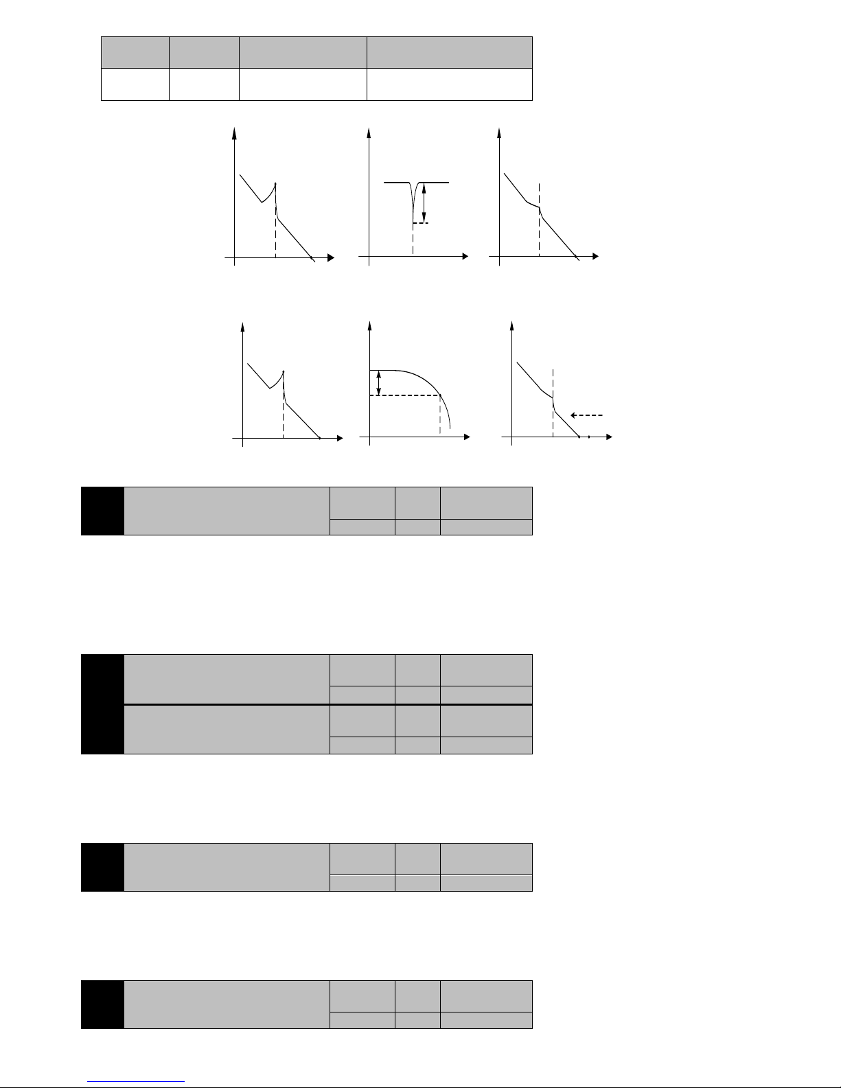
73
Filter type
Suitable
occasion
Advantages
disadvantages
is not suitable for frequent drift
occasions
Notch
filter
gain
+
Notch depth
P1-50
resonance frequencyP1-49
=
Mechanical
response
gain
B.W
Resonance point was
suppressed
Mechanical
response
gain
B.W
Resonance
point
resonance frequencyP1-49 resonance frequencyP1-49
Constant
bandwidth
Figure7-14 The principle of vibration suppression using notch filter
+
Mechanical
response
gain
B.W
Resonance point was
suppressed
Low
pass
filter
gain
Frequency
-3db
0db
Cutoff
frequency and
P1-22
correlation
Mechanical
response
gain
B.W
Resonance
point
Resonance
frequency
=
Bandwidth reduction
Figure 7-15 The Principle of vibration suppression using low pass filter
P1-53
Stop mode selection
Initail value
Unit
Communication
Address
0
-
2135H
Control Mode:P S T
Range:0~1
Data size:16bit
Display mode:Decimal system
Parameter function:set stop mode
P1-53=0:when servo OFF, free parking
P1-53=1:when servo OFF, slow down stop
P1-54
Servo ON- receive instruction delay time
Initail value
Unit
Communication
Address
200
ms
2136H
P1-55
Brake command - servo OFF delay time
Initail value
Unit
Communication
Address
200
ms
2137H
Control Mode:P S T
Range:0~500
Data size:16bit
Display mode:Decimal system
Parameter function:Please refer to section 3.7.2.
P1-56
Braking command action speed
Initail value
Unit
Communication
Address
50
rpm
2138H
Control Mode:P S T
Range:1~1000
Data size:16bit
Display mode:Decimal system
Parameter function:Please refer to section 3.7.2.
P1-57
Servo OFF- brake command waiting
time
Initail value
Unit
Communication
Address
500
ms
2138H
Page 74
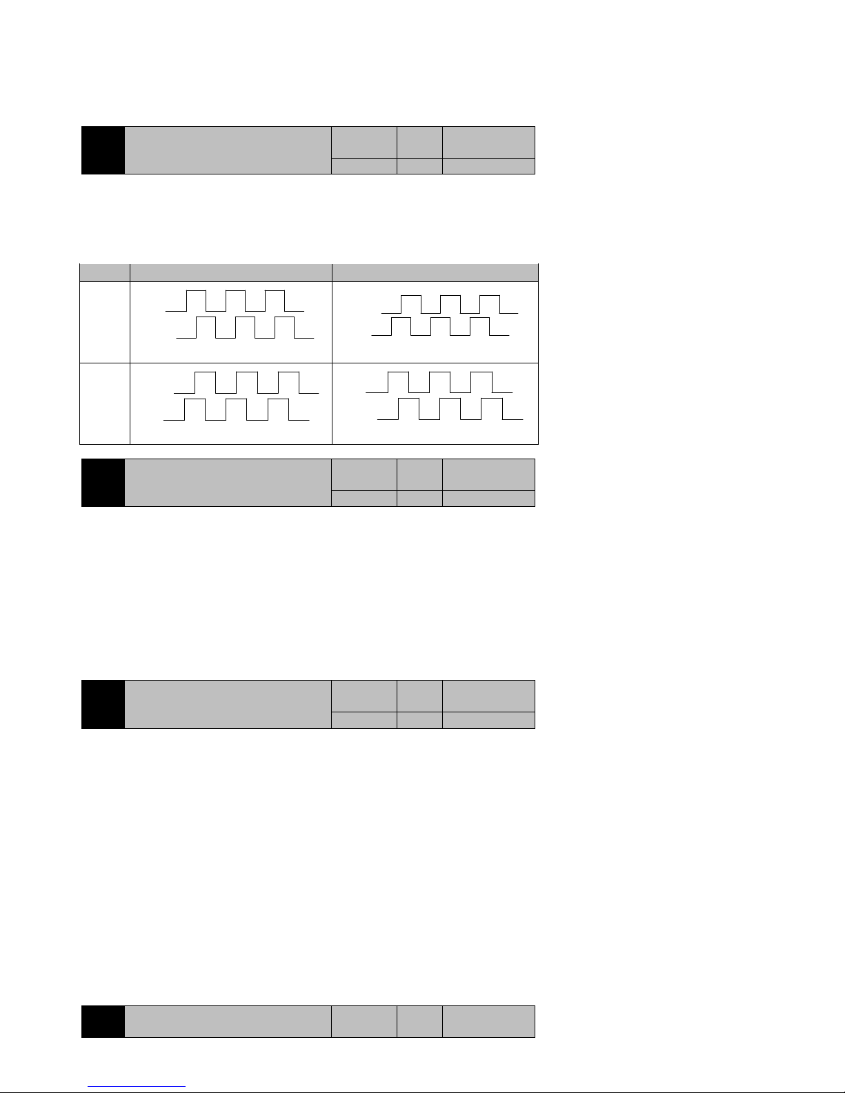
74
Control Mode:P S T
Range:1~1000
Data size:16bit
Display mode:Decimal system
Parameter function:Please refer to section3.7.2.
P1-58
Frequency division output pulse
direction selection
Initail value
Unit
Communication
Address
0
-
213AH
Control Mode:P S T
Range:0~1
Data size:1bit
Display mode:Decimal system
Parameter function:
Table7-4 Output pulse feedback direction
Forward
Inversion
P1-58=0
PA+-
PB+-
A phase lead B phase 90°
PA+-
PB+-
B phase lead A phase 90°
P1-58=1
PA+-
PB+-
B phase lead A phase 90°
PA+-
PB+-
A phase lead B phase 90°
P1-60
Fault display selection
Initail value
Unit
Communication
Address
0
-
213CH
Control Mode:P S T
Range:0~3
Data size:16bit
Display mode:Decimal system
Parameter function:Select display which fault in the drive digital tube
P1-60=0:Last fault;
P1-60=1:The first 1 failures;
P1-60=2:The first 2 failures;
P1-60=3:The first 3 failures
Servo drive a total of 4 times the recent the information failure of failure, through this function, it can choose monitoring parameters of
P0-18 ~ P0-22 to show which failure.
P1-61
System parameter initialization
Initail value
Unit
Communication
Address
0
-
213DH
Control Mode:P S T
Range:0~65535
Data size:16bit
Display mode:Decimal system
Parameter function:System parameter initialization related setting. Stop setting, power up again.
P1-61=1:When power up again, removal of fault record;
P1-61=65535:When power up again, all function code parameters are returned to the factory default value (except PE group);
P1-61= Other values:No operation.
7.3 P2-xx Internal multi segment position (Pr) control parameter
This set of features can be enabled if the servo driver is currently in a position mode (P1-00=1) and the command source is an internal multi
segment instruction (P1-01=1).
P2 - xx group a total of 64 functional code, is divided into 16 groups, corresponding to the multi segment location directive PR1 to pr16. Since
the beginning of P2-00, each of the 4 functional code to set a target location, to achieve the target position allows the uniform speed, after the
positioning completion of the waiting time.
The following is a detailed description of the four parameters P2-00~P2-03 involved in the first paragraph of PR1, the other 15 sections of the
same, no longer detail. Please refer to figure 7-17.
P2-00
The number of internal position
instruction 1 pulses high five
Initail value
Unit
Communication
Address
Page 75
75
1
ppr
2200H
P2-01
The number of internal position
instruction 1 pulses low four
Initail value
Unit
Communication
Address
0
ppr
2201H
Control Mode:P
Range:P2-00:-30000~+30000;P2-01:-9999~+9999
Data size:16bit
Display mode:Decimal system
Parameter function:Set the target pulse number of first position moves.
The calculation formula is: Pr1 segment total pulse number =10000* P2-00 + P2-01
Please pay special attention to when computing, P2-00 and P2-01 are a symbol number.
For example:
If the P2-00 input13, P2-01 input1050, set the target pulse number to 131050.
If the P2-00 input is 13, P2-01 input -1050, target pulse number is 128950.
If the P2-00 input -13, P2-01 input-1050, set the target pulse number 131050 reverse.
If the P2-00 input -13, P2-01 input 1050, set the target pulse number 128950 reverse.
P2-02
The movement speed of internal position
command 1
Initail value
Unit
Communication
Address
100
rpm
2202H
Control Mode:P
Range:-9000~9000
Data size:16bit
Display mode:Decimal system
Parameter function:Set the speed of the first section of the position to run at a constant speed.
NOTE:
1: set speed is positive, the motor in accordance with the number of pulses set forward, whereas
the motor according to the number of pulses set in reverse.
2: If the position pulse less, may not reach this speed when the motor running actually.
Therefore, please understand the meaning of the parameters:the upper limit of the operation
speed of the motor during the execution Pr1 segment position.
P2-03
After the completion of the Pr1 into the
Pr2 waiting time
Initail value
Unit
Communication
Address
1.0 S 2203H
Control Mode:P
Range:0.0~3000.0
Data size:16bit
Display mode:Decimal system
Parameter function: When P1-03=0 or 1,after the completion of the first stage position command, wait for this time then start the
implementation of the second stage position command. If P1-03 = 2, this parameter is invalid.
Figure 7-17 shows a schematic when run in command sequence. External terminal control mode switching schematic is similar but has the
difference. Please refer to P1-03 for explanation.
speed/rpm
Pr1
...
P2-02
P2-03
Pr2
P2-06
Rated speed
Pr16
P2-63
P2-62
Position
10000*P2_00+P2_01
Time
10000*P2_04+P2_05
...
10000*P2_60+P2_61
P2-07
P2-59
Figure7-17 Multi-position operation schematic
NOTE:
1: When using the internal multistage position, whether it is run by the command sequence or
external terminal switching mode, if you modify the current segment operating parameters,
the modified parameters will not be executed, will take effect when the next execution of the
segment.
2: When using an external terminal switching mode during the execution period of the position
command, the servo drive will not terminate execution of the current segment position
command due to DI sub-state changes.
3: When using the external terminal switching mode, after the current position instruction
execution is completed, the servo drive waits to receive the falling of CTRG, according to the
state of the terminal DI at that time, executes position instruction of the corresponding segment.
Page 76
76
7.4 P3-xx Internal multi-speed control parameters
If servo speed mode (P1-00 = 0) is adopted on the current , and the instruction source is internal multistage instruction (P1-05 = 4), you can
enable the function.
P3 group has about 32 parameters, which is divided into 16 groups, corresponding to a multi-speed command spd1 to spd16. Since P3-00,
every two parameters set period of time and speed multi-speed operation.
The following examples only spd1 group stated: P3-00 set running speed of spd1 command; P3-01 set running time of spd1 instruction. For
example, when P3-00 = 400, P3-01 = 1.0, corresponding to the instruction spd1 interpreted as motor operates 1s with 400rpm speed.
P3-00
Internal speed instruction register 1
Initail value
Unit
Communication
Address
0
rpm
0300H
2300H
Control Mode:S
Range:-rated speed~+ rated speed
Data size:16bit
Display mode:Decimal system
Parameter function:The first segment speed of internal multispeed
If when servo is speed mode (P1-00 = 0) on the current, and the instruction source is the internal value given (P1-05 = 0), this code
specifies speed. For example, if P3-00 = 400, after S-ON the motor has been to 400rpm.
P3-01
Internal speed instruction 1 running
time setting
Initail value
Unit
Communication
Address
1.0 S 2301H
Control Mode: S
Range:0.1~6553.5
Data size:16bit
Display mode:Decimal system
Parameter function:The first segment running time of internal multispeed
According to the instruction sequence running is illustrated below
speed/rpm
Spd1 ...
P3-00
P3-01
Spd16
P3-02
Rated speed
P3-30
Time
P3-03
Spd2
0
P3-31
Figure7-18 Multi-speed operation
NOTE:
1: If modify the parameters currently running segment, the modified parameters will not be
executed until the next time , it takes effect when you execute this segment, when adopt internal
multi-speed, and run with instruction sequence ( P1-05 = 4, P1-06 = 0 or 1).
2: Use an external terminal switching multispeed that P1-06 = 2, each of the internal speed
command running time parameter is invalid, servo motor speed depending on the state of the
corresponding segment external terminals. At the same time, the current speed value as long as
modifications,it will be executed immediately.
7.5 P4-xxTorque control parameter
P4-00
Internal digital torque
Initail value
Unit
Communication
Address
100.0 % 2400H
Control Mode: T
Range:-300.0~300.0
Data size:16bit
Display mode:Decimal system
Parameter function:When P1-18=0 时,set the percentage of the motor output torque reference of the motor rated torque.
P4-01
Speed limit value during torque control
Initail value
Unit
Communication
Address
100
rpm
2401H
Control Mode: T
Range:0~motor rated speed
Page 77
77
Data size:16bit
Display mode:Decimal system
Parameter function:When P4-02=0 时,set the maximum motor speed allowed by torque control
P4-02
Torque speed limit command source
Initail value
Unit
Communication
Address
0 - 2402H
Control Mode:T
Range:0~3
Data size:16bit
Display mode:Decimal system
Parameter function:Select the source, which limit the size of torque mode of operation (P1-00 = 2) speed .
P4-02=0:P4-01given
P4-02=1:Analog1given
P4-02=2:Analog2given
P4-02=3:Retention
P4-03
Torque speed limited instruction gain
Initail value
Unit
Communication
Address
Motor rated
speed
rpm
2403H
Control Mode:T
Range:0~motor rated speed
Data size:16bit
Display mode:Decimal system
Parameter function:When P4-02 is set to limit the motor running speed under torque running mode by analog, setting speed corresponding to
10V analog. At this point, if external analog is 10V, the maximum motor speed will be limited in set of this function parameters.
To limit speed by the value of P4-01
Set the gainP4-03 of
analog
P4-02
0
1
2
To limit speed by the external AT1 given
To limit speed by the external AT2 given
NOTE:On torque mode, when P1-48 (torque limit source selection) is set to 2/3/4, that
external analog and P1-46, P1-47 are limiting the size of torque meanwhile, while P4-02
(Torque speed limit instruction source) is set to 1/2, which limited the speed of the motor by
external analog and select the same analog source (such as both AI1), then the analog limit both
speed and torque.
P4-05
Torque command compensation
Initail value
Unit
Communication
Address
0.0 % 2405H
Control Mode: T
Range:0.0~10.0
Data size:16bit
Display mode:Decimal system
Parameter function:Superimposing a compensation amount based on the original torque command , the reference is the motor rated torque.
7.6 P5-xx Gain tuning parameters
P5-00
Position regulator proportional gain (KP)
Initail
value
Unit
Communication
Address
30.0
rad/s
2500H
Control Mode:P S T
Range:1.0~2000.0
Data size:16bit
Display mode:Decimal system
Parameter function:Setting position proportional regulator gain KPP
This parameter determines the responsiveness of the position loop, the larger KPP value is set the higher position loop frequency responses, the
better to follow the instruction of position, position error amount is smaller, the positioning setting time is shorter. However, too large setting
may cause the system to generate vibration or positioning will overshoot (Overshoot) Under normal circumstances:
The outer ring
The inner ring
Position loop bandwidth<Speed loop bandwidth<Current loop bandwidth
When the inner ring much faster than the outer ring, the inner ring can be seen straight, at this time the position loop can be modeled as the
Page 78
78
first order low pass filter model without a static error, transfer function:
*
1
1
1
s
s
s
KPP
position loop response frequency:
()
2
KPP
Hz
0
t
Instruction
position
63.2%
The actual
position
1/KPP Unit s
7-19 Position regulator proportional gain
The time required to reach 63.2% of a target position is the reciprocal of position regulator proportional gain.
P5-01
Position regulator proportional gain
fluctuation ratio
Initail value
Unit
Communication
Address
50 % 2501H
Control Mode:P S
Range:10~500
Data size:16bit
Display mode:Decimal system
Parameter function:When the gain switching condition is satisfied, it‘s the rate of change for target position regulator proportional gain.
P5-02
Front position regulator feedforward
gain
Initail value
Unit
Communication
Address
0 % 2502H
Control Mode:P
Range:0.0~100.0
Data size:16bit
Display mode:Decimal system
Parameter function:Set front position regulator feed forward gain
When smooth change of position control command, increase this gain can reduce the position track deviation.
When position control instruction is not smooth change, reduce this gain can improve the resonance condition of mechanical operation.
P5-03
Position feed forward smoothing
constant
Initail value
Unit
Communication
Address
5
ms
2503H
Control Mode:P
Range:2~100
Data size:16bit
Display mode:Decimal system
Parameter function:Set the first order filter time constant of feed forward gain of position regulator.
When smooth change of position control command, decrease this smoothing constant can improve the position track deviation.
When position control instruction is not smooth change, increase this smoothing constant can improve the resonance condition of
mechanical operation.
P5-04
Proportional gain of speed regulator
KVP
Initail value
Unit
Communicatio
n Address
350.0
rad/s
2504H
Control Mode:P S
Range:0.1~5000.0
Data size:16bit
Display mode:Decimal system
Parameter function:When the gain value of the speed control is increased, the speed of the response can be improved. It will produce vibration
and noise when it is too large.
This parameter determines the speed control loop response, the greater KVP set up the higher speed loop frequency response, the speed of the
instructions to follow the better, but it‘s easy to trigger a mechanical resonance when to set large. The response frequency of the speed loop must
4 ~ 6 times higher than the response frequency of the position loop, when the position response frequency is higher than speed response
frequency, the system may produce jitter or positioning will have overshoot phenomenon. The calculation of the response frequency of the speed
loop is as follows:
When the estimated or set P5-08 is equal to the true
/JL JM
:
Page 79
79
1 P5 08
2 1 /
KVP
f Hz
JL JM
JL:Load inertia,JM:Motor inertia
P5-05
Speed regulator integration time
constant
Initail value
Unit
Communication
Address
10.0
ms
2505H
Control Mode:P S
Range:0.1~3000.0
Data size:16bit
Display mode:Decimal system
Parameter function:When the integral time of the speed regulator is increased, it can improve the speed response ability and decrease the
speed control deviation. However, it will produce vibration and noise when it is too large.
Speed loop integral can effectively eliminate the steady state error of the velocity, and the fast response is slight. The integral time constant
i
T
of
the speed loop is reduced under the condition that the mechanical system doesn‘t a produce vibration or noise, so as to increase the rigidity of
the system and reduce the error of the steady state. If the load inertia ratio is larger or mechanical system has resonance factor, it is necessary to
confirm that the integral time constant of the velocity loop is enough large, otherwise the mechanical system is easy to produce resonance. If the
load inertia ratioG is set correctly
/
LM
G J J
, the velocity integral time constant
i
T
is obtained by the following formula:
5000
()
2 ( )
v
Ti ms
f Hz
The greater the load inertia,the greater the time constant of the velocity integral under normal circumstances.
P5-06
Speed regulator proportional gain
fluctuation ratio
Initail value
Unit
Communication
Address
50 % 2506H
Control Mode:P S
Range:10~500
Data size:16bit
Display mode:Decimal system
Parameter function:When the gain switching condition is satisfied, the rate of change for target speed regulator proportional gain
target speed regulator proportional gain
P5-07
Gain adjustment mode selection
Initail value
Unit
Communication
Address
0 - 2507H
Control Mode:P S
Range:0~2
Data size:16bit
Display mode:Decimal system
Parameter function:
P5-07=0:Manual mode
The related parameters of position and speed regulator gain P5-00、P5-04、P5-05 and load inertia ratio P5-08 all set by the users
themselves.
The speed bandwidth is invalid under this mode.
When switching from automatic or semi-automatic mode to manual mode, these gain parameters (P5-00, P5-04, P5-05, P5-08)
will maintain the original value that semi-automatic mode automatically calculated.
P5-07=1:Semi-automatic mode (non-continuous adjustment)
Users only need to set speed bandwidth P5-11, this system can calculate the value of P5-00, P5-04, P5-05 based on it. At the
same time should be given appropriate P5-08Initail value, the actual value will automatically recognize and automatically
overwritten by the system at runtime.
After the system detects inertia becoming stable, stopping the identification of P5-08, and storing the results to P5-08.
P5-07=2:Automatic mode(continuous adjustment)
Users only need to set speed bandwidth P5-11, this system can calculate the value of P5-00, P5-04, P5-05 based on it. The load
inertia ratio will automatically recognize by the system .
System estimate continuously the load inertia ratio, updated P5-08 in real time.
Use manual mode for the following:
When using automatic and semi-automatic mode ineffective.
The mechanical parts do not connect firmly, for example, there is a reverse gap.
The mechanical rigidity is very low.
The load inertia ratio is too large (over 20 times), or too small (less than 3 times) .
The load inertia is large fluctuations.
There is a continuous low speed (less than 100RPM) operation.
The deceleration time is not more than 2000rpm/s.
The acceleration time of speed not less than 100RPM and not less than 2000rpm/s did not last for at least 50ms.
The acceleration and deceleration torque is smaller than the friction torque.
Page 80
80
P5-08
Load inertia ratio
Initail value
Unit
Communication
Address
0.01 - 2508H
Control Mode:P S
Range:0.01~655.35
Data size:16bit
Display mode:Decimal system
Parameter function:Set the ratio of load inertia and motor rotor inertia
In the P5-07=0 that is, gain adjustment for manual mode should be as accurate as possible, while in the P5-07=1, 2, gain automatic and
semi-automatic adjustment mode allows some deviation.
5 08 /
LM
P J J
L
J
Load inertia,
M
J
Motor rotor inertia ratio
P5-09
Offline load inertia ratio self-learning
torque
Initail value
Unit
Communication
Address
50 % 2509H
Control Mode:P S
Range:10~200
Data size:16bit
Display mode:Decimal system
Parameter function:Offline learning load inertia ratio, the output torque of the motor compared to the percentage of motor rated torque.
The greater the set value, the greater the impact will be caused by the mechanical shock, but the identification time is shorter, please according
to the appropriate value of the machine set.
P5-11
Speed bandwidth
Initail value
Unit
Communication
Address
60
Hz
250BH
Control Mode:P S
Range:1~1000
Data size:16bit
Display mode:Decimal system
Parameter function:Set the speed bandwidth of system
When P5-07=0,this function is invalid.
When P5-07=1、2, this parameter must be set when using the semi-automatic and automatic gain adjustment mode. The system can
calculate the value of P5-00, P5-04, P5-05 related to position and speed regulator based on this parameter.
1~50Hz:Low rigidity, low response
51~250Hz:Medium rigidity, medium response
251~550Hz:High rigidity, high response
P5-12
PDFF control coefficient
Initail value
Unit
Communication
Address
100 % 250CH
Control Mode:P S
Range:0~100
Data size:16bit
Display mode:Decimal system
Parameter function:PDFF control coefficient=0, IP controller
PDFF control coefficient=100, PI controller
PDFF control coefficient=1~99, PDFF controller
When using the IP controller, the running motor speed will not overshoot, but the response will be slow.
When using the PI controller, the motor running speed will be overshoot, but the response is rapid.
PDFF controller integrated IP and PI controller, in order to obtain the effect of reducing overshoot and speed up the response of the system. The
more parameter closes to 0, the stronger the IP function, and vice versa.
P5-13
Gain switching condition
Initail value
Unit
Communication
Address
0 - 250DH
Control Mode:P S
Range:0~18
Data size:16bit
Display mode:Decimal system
Parameter function:When P5-07=0, the gain adjustment mode is the manual mode, selecting the gain switching conditions.
When P5-07=1 and 2, the gain adjustment mode is semi-automatic and automatic mode, the function is invalid.
P5-13=0~9, for gain switching:
P5-13=0: turn off gain switching function.
P5-13=1: retention
P5-13=2: under position Mode Control, the position error is greater than the set value of the
Page 81
81
parameter P5-16.
P5-13=3: the position command frequency is greater than the set value of the parameter
P5-16.
P5-13=4: the servo motor rotation speed is greater than the value of parameter P5-16.
P5-13=5: retention
P5-13=6: under position Mode Control, the position error is less than the set value of the
parameter P5-16.
P5-13=7: the position command frequency is less than the set value of the parameter P5-16.
P5-13=8: the servo motor rotating speed is less than the set value of the parameter P5-16.
P5-13=9: retention
P5-13=10~17 when switching for PI-P:
P5-13=10: retention
P5-13=11: under position Mode Control, the position error is greater than the set value of
the parameter P5-16.
P5-13=12: the position command frequency is greater than the set value of the parameter
P5-16.
P5-13=13: when the servo motor rotation speed is greater than the reference value of P5-16.
P5-13=14: retention
P5-13=15: position Mode Control, the position error is less than the set value of the
parameter P5-16.
P5-13=16: the position command frequency is less than the set value of the parameter
P5-16.
P5-13=17: when the servo motor rotating speed is less than the set value of the parameter
P5-16.
P5-14
Gain switching time
Initail value
Unit
Communication
Address
5
ms
250EH
Control Mode:P S
Range:0~3000
Data size:16bit
Display mode:Decimal system
Parameter function:When the gain switching condition is satisfied, the gain is changed linearly to the target gain value during this time (0:
close the function). Please refer to figure 7-20.
P5-15
Gain delay time
Initail value
Unit
Communication
Address
5
ms
250FH
Control Mode:P S
Range:0~3000
Data size:16bit
Display mode:Decimal system
Parameter function:When the gain switching condition is achieved, the switching condition must maintain the time set by the parameter then
to start the switch, so as to avoid the error caused by the interference and other factors, the system isn‘t stable. Please refer to figure 7-20.
P5-16
Gain switching threshold
Initail value
Unit
Communication
Address
100
1puls
0.1Kpps
1rpm
2510H
Control Mode:P S
Range:0~32767
Data size:16bit
Display mode:Decimal system
Parameter function:Set gain switching threshold
When the motor stops, switch to low gain to suppress vibration and sharp noise.
When the motor stops, switch to high gain in order to increase the rigidity of servo.
When the motor runs, switch to higher gain to obtain better instruction follow
Performance and smaller position time.
According to the operation of load equipment switch different gain in order to
achieve optimal control.
Page 82
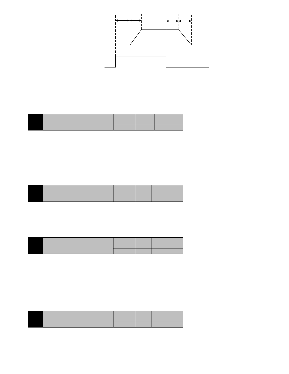
82
Not
satisfied
Switching
condition
Gain
combination
First gain
Delay time Switching time
Second gain
Delay time Switching time
First gain
satisfied
Not
satisfied
Figure7-20 Gain switching process
When the switching condition is satisfied, the gain is switched to second gain. If the switching condition is not satisfied during the second
gain operation, the gain is switched to a first gain.
Switch condition change state must maintain the delay time setting by parameter P5-15 to be able to switch, so as not to switch by the
interference. When switching, the current gain combination is in accordance with the setting time of the parameter P5-14, the linear
smoothing gradient to the target gain combination, the various parameters of combination simultaneously changes, to avoid mechanical
shock caused by sudden changes of parameters. Once the switch is started, even if the change status of the switch is changing again, the
delay time can be recalculated after the switch is completed.
P5-17
Control loop coefficient
Initail value
Unit
Communicatio
n Address
4 - 2511H
Control Mode:P S
Range:1~32
Data size:16bit
Display mode:Decimal system
Parameter function:Only in P5-07=1, 2, that is, gain adjustment mode is semi-automatic and automatic mode, this parameter is effective. So
as to determine the relationship between speed bandwidth and position bandwidth .
Speed bandwidth= Position bandwidth*P5-17
There is no parameters about position bandwidth can be set. The parameters control based on the theory of automatic control that the speed
loop bandwidth should be at least 4 times than the position loop bandwidth. Generally do not adjust, especially not a small adjustment.
P5-19
Low frequency rigidity coefficient
Initail value
Unit
Communication
Address
1.0 - 2513H
Control Mode:P S
Range:0.5~4.0
Data size:16bit
Display mode:Decimal system
Parameter function:Only in P5-07=1, 2, gain adjustment mode is semi-automatic and automatic mode, this parameter is effective. It used to
set the rigidity of the speed loop at low frequency, that is the integral time constant of the speed regulator at low frequency. It‘s meaning is:
P5-20
External disturbance resistance gain
Initail value
Unit
Communication
Address
0.0 % 2514H
Control Mode:P S
Range:-100.0~100.0
Data size:16bit
Display mode:Decimal system
Parameter function :External disturbance compensation after disturbance observation
It used to reduce the speed change of load disturbance. Its meaning is:
Compensated torque = Compensating torque + Observed disturbance quantity *P5-20
After the disappearance of the observed disturbance, the torque will be cancelled immediately.
7.7 P6-xx Input and output(DI/DO)parameter
P6-00
DI Filter settings
Initail value
Unit
Communication
Address
2
ms
2600H
Control Mode:P S T
Range:0~20
Data size:16bit
Display mode:Decimal system
Parameter function:Set the filter time of the DI terminal, stop setting after motor stops, take effect immediately.
Page 83
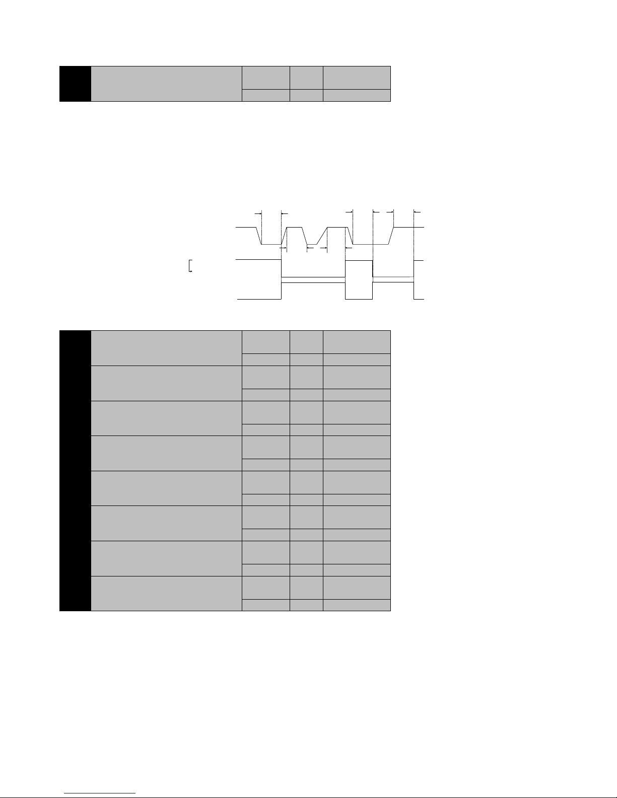
83
When there is a strong external interference, in order to prevent external interference, you can set the filter time for the DI terminal. Its meaning
is that the signal of the DI terminal must maintain the time more than the P6-00 setting time and will be recognized as the valid signal by drive.
For example, P6-00 is set to 2, the signal of the DI terminal must maintain the 2ms will be recognized as effective by drive.
P6-01
DI Level logic
Initail value
Unit
Communication
Address
00000000
-
2601H
Control Mode:P S T
Range:00000000~11111111
Data size:16bit
Display mode:Binary system
Parameter function:Set the level logic of each DI terminal, stop setting after motor stops and re-power effective.
0 0 0 0 0 0 0 0
DI8 DI7 DI6 DI5 DI4 DI3 DI2 DI1
8 loads way DI can be set, for a certain, bit=0, the external input low effective; if bit=1, then the external input high effective.
2ms
2ms
2ms
Actual DI
level
2ms
2ms
Low level effective
High level
effective
P6-01=1
P6-01=0
DI effective
DI effective
DI Invalid
DI Invalid
DI effective
Figure7-21 DI Terminal filter and level
P6-02
DI1 function code
Initail value
Unit
Communication
Address
1 - 2602H
P6-03
DI2 function code
Initail value
Unit
Communication
Address
2 - 2603H
P6-04
DI3 function code
Initail value
Unit
Communication
Address
3 - 2604H
P6-05
DI4 function code
Initail value
Unit
Communication
Address
4 - 2605H
P6-06
DI5 function code
Initail value
Unit
Communication
Address
5 - 2606H
P6-07
DI6 function code
Initail value
Unit
Communication
Address
6 - 2607H
P6-08
DI7 function code
Initail value
Unit
Communication
Address
7 - 2608H
P6-09
DI8 function code
Initail value
Unit
Communication
Address
8 - 2609H
Control Mode:P S T
Range:0~99
Data size:16bit
Display mode:Decimal system
Parameter function:Set the function of the DI1~DI8 terminal, refer to table 7-5. Stop setting after motor stops and re-power effective.
External 8 DI corresponding function settings, can be set to a range of 0~99, but the current part of the retention items.
As any DI to set the function code, the corresponding DI is valid, the selected event occurs. Such as P6-02=1, the DI1 is set to serve as the
Page 84
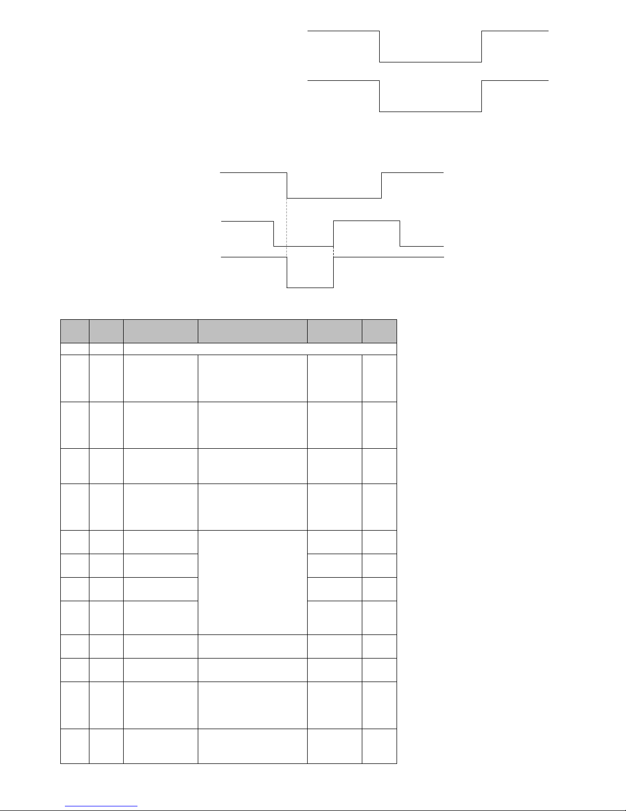
84
enable function, when the DI1 is valid, the servo S-ON.
DI1
/S-ON
Terminal
effective
Enable
effective
Terminal
invalid
Enable
invalid
Terminal
invalid
Enable
invalid
The different DI can be set to the same function, the corresponding logical relations is ―and‖, that when the D1& effective, the
corresponding function of the event will occur. Such as P6-03=1, P6-02=1, DI1 and DI2 at the same time effective, servo ON; when there
is an invalid, servo OFF.
DI1
DI2
/S-ON
Terminal
invalid
Enable
effective
Terminal
effective
Terminal
effective
Terminal
invalid
Terminal
invalid
Terminal
invalid
Terminal
effective
Enable
invalid
Enable
invalid
Table7-5 Digital input (DI) function definition table
Setting
Name
Function
Description
Trigger mode
Operation
mode
0
Disabled
Terminal invalid
1
S-ON
Servo enable
ON- servo motor power on
enable
OFF- servo motor enable
disabled
Level
triggered
P S T
2
Alarm reset signal
ON- in the case of abnormal
conditions has been lifted,
reset the fault and alarm can
be reset.
Edge Trigger
P S T
3
P-CLR
Position control pulse
deviation counter
clear
Trigger mode refer to P1-34
definition
Edge/ Level
Trigger
P
4
DIR-SEL
Speed instruction
direction selection
OFF- default command
direction
ON- directive reverse
direction
Level
triggered
S
5
CMD0
Internal instruction
bit0
In position mode control, the
signal is a position
multi-segment switching
function;
In speed mode control, the
signal is the speed
multi-segment switching
function
Level
triggered
P S
6
CMD1
Internal instruction
bit1
Level
triggered
P S
7
CMD2
Internal instruction
bit2
Level
triggered
P S
8
CMD3
Internal instruction
bit3
Level
triggered
P S
9
CTRG
Internal instruction
trigger
Multi position trigger
condition
Edge Trigger
P
10
MSEL
Control Mode
switching
Used to mixed Mode Control
switching
Level
triggered
P S T
11
ZCLAM
P
Analog speed
command Enable
fixed zero
OON- zero fixed function
enable
OOFF- zero fixed function
ban
Level
triggered
S
12
INHIBIT
Pulse inhibit
ON- prohibit instruction pulse
input
OFF-allow instruction pulse
Level
triggered
P
Page 85
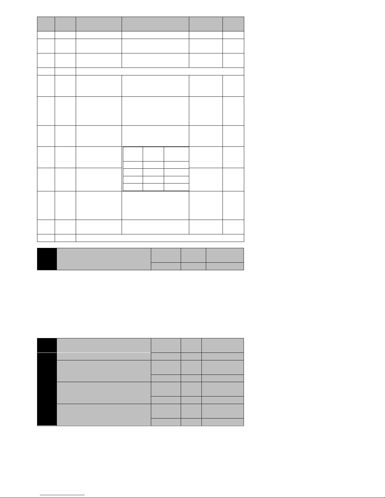
85
Setting
Name
Function
Description
Trigger mode
Operation
mode
input
13
P-OT
Forward driving ban
OFF- prohibit forward drive
ON-allow forward drive
Level
triggered
P S T
14
N-OT
Prohibit reverse
drive
OFF- prohibit reverse drive
ON- allow reverse drive
Level
triggered
P S T
15/16
Retention
Function invalid
17
Positive jog
ON- input in accordance with
instructions given
OFF- run command stop input
Level
triggered
S
18
Negative jog
ON- reverse input in
accordance with a given
instruction
OFF- run command stop input
Level
triggered
S
19
Torque instruction
direction selection
OFF- default orientation
ON- instruction Reverse
Level
triggered
T
20
GNUM0
Electronic Gear
Ratio numerator
choose 0
GNUM
1
GNUM0
code
0 0 P1-27 0 1
P1-29
1 0 P1-30
1 1 P1-31
Level
triggered
P
21
GNUM1
Electronic Gear
Ratio numerator
choose 1
Level
triggered
P
22
ORGP
External detector
input
Rising edge: the external
detector is effective
Falling edge: the external
detector is not valid
Edge Trigger
P S T
23
SHOM
Origin regression
ON:Start origin regression
function
Level
triggered
P S T
Retention
Function invalid
P6-12
DO level logic
Initail value
Unit
Communicatio
n Address
0000 - 260CH
Control Mode:P S T
Range:0000~1111
Data size:16bit
Display mode:Binary system
Parameter function:Set the logic of the 4 DO output terminal. Stop setting after motor stops and re-power effective.
0 0 0 0
DO4 DO3 DO2 DO1
0: The bit corresponds to DO terminal active low, set low when the event is active, maintain a high level invalid.
1: The bit corresponds to DO terminal active high, set high when the event is active, maintain a low level invalid.
P6-13
DO1 function code
Initail value
Unit
Communication
Address
1 - 260DH
P6-14
DO2 function code
Initail value
Unit
Communication
Address
2 - 260EH
P6-15
DO3 function code
Initail value
Unit
Communication
Address
8 - 260FH
P6-16
DO4 function code
Initail value
Unit
Communication
Address
12 - 2610H
Control Mode:P S T
Range:0~99
Data size:16bit
Display mode:Decimal system
Parameter function:Set the event that corresponds to each DO, see table 7-6. shutdown settings, re - power up.When the event occurs, it is set
to be the output of the DO terminal for the event. If the P6-13=1 is ready, the DO1 terminal outputs a low level (P6-12 bit =0).
Page 86
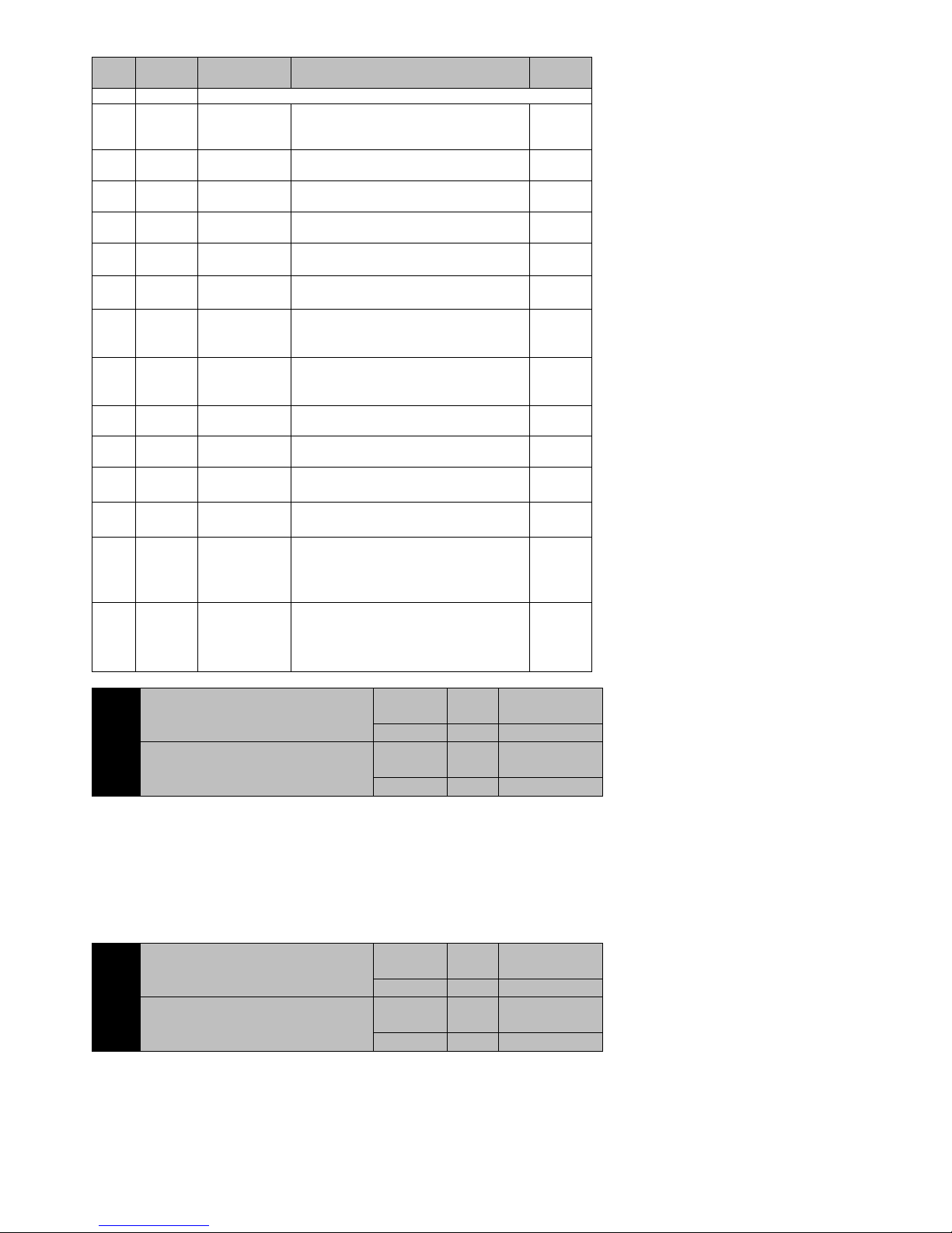
86
Table7-6 Digital output (DO) function definition table
Setting
value
Name
Function
Description
Operation
mode
0
Disable
Terminal invalid
1
S-RDY+-
SRDY
Valid-SRDY, can receive S-ON instructions
Invalid-SRDY, cannot receive S-ON
instructions
P S T
2
BK+-
Brake control
Valid-release brake
Invalid-close brake
P S T
3
TGON+-
Motor rotation
Valid-motor keep rotating
Invalid-motor stop rotating
P S T
4
ZER0+-
Motor zero
speed
Valid-motor speed is zero
Invalid-motor speed is not zero
P S T
5
V-CLS+-
Speed approach
Valid:when speed control, ǀ motor actual
speed-speed instruction ǀ˂P1-42 setting
S
6
V-CMP+-
Speed reach
Valid:when speed control, ǀ motor actual
speed-speed instruction ǀ˂P1-43 setting
S
7
PNEAR+-
Position
approach
Valid : when position control mode ,
positional deviation pulses˂ positioning
close to width P1-32 setting
P
8
COIN+-
Position reach
Valid : when position control mode ,
positional deviation pulses˂ positioning
close to width P1-33 setting
P
9
C-LT+-
TLML
Valid-motor torque is limited
Invalid-motor torque is unlimited
P S
10
V-LT+-
Speed limited
signal
Valid-motor speed is limited
Invalid-motor speed is unlimited
T
11
WARN+-
Warning output
Valid:warning event
Invalid:no warming event
P S T
12
ALM+-
Fault output
Valid:fault event
Invalid:no fault event
P S T
13
Tcmp+-
Torque reach
signal
Valid : motor output torque reach fixed
value
Invalid:motor output torque can not reach
fixed value
T
14
Home+-
ZRN signal
Valid:ZRN signal complete
Invalid:ZRN signal can not complete
P S T
P6-19
AI1 Offset adjustment
Initail value
Unit
Communication
Address
0
mV
2613H
P6-20
AI2 Offset adjustment
Initail value
Unit
Communication
Address
0
mV
2614H
Control Mode:P S T
Range:-1000~1000
Data size:16bit
Display mode:Decimal system
Parameter function:Because of the circuit, the voltage will have a certain deviation, such as when the external given to 0V, the system may be
collected the voltage 200mv. At this time can be corrected by this parameter, similar to the mechanical zero adjustment function.
If the AI1, AI2 given 0V to collect the XmV voltage, then set the P6-19/20 to X, you can eliminate the deviation.
P6-22
AI1 Filtering time
Initail value
Unit
Communication
Address
2
ms
2616H
P6-23
AI2 Filtering time
Initail value
Unit
Communication
Address
2
ms
2617H
Control Mode:P S T
Range:0~1000
Data size:16bit
Display mode:Decimal system
Parameter function:About analog value through the AI1, AI2 input is adopted the first order low-pass filter. It can reduce the external
electromagnetic interference caused by analog fluctuations. But the system response to slowly due to setting too large,.
Page 87
87
P6-25
AO1 Offset adjustment
Initail value
Unit
Communication
Address
0
mV
2619H
P6-26
AO2 Offset adjustment
Initail value
Unit
Communication
Address
0
mV
261AH
Control Mode:P S T
Range:0~1000
Data size:16bit
Display mode:Decimal system
Parameter function:The EA100 servo has two analog output channels, which is convenient for the user to monitor the running state of the
servo system by the way of receiving the analog quantity. When the output voltage is DC offset, the DC offset can be adjusted by adjusting the
parameters.
If AO1, AO2 in the output should be 0V, the actual output of the detected DC voltage is XmV, then set the P6-25/26 to X, then can eliminate
bias.
P6-27
AO1 Functional Planning
Initail value
Unit
Communication
Address
0 - 261BH
P6-28
AO2 Functional Planning
Initail value
Unit
Communication
Address
1 - 261CH
Control Mode:P S T
Range:0~4
Data size:16bit
Display mode:Decimal system
Parameter function:set the meaning of AO terminal output
P6-27/28= 0:motor speed;
P6-27/28= 1:speed instruction;
P6-27/28= 2:torque instruction;
P6-27/28= 3:positional deviation (after electronic gear ratio calculation);
P6-27/28= 4:the speed of instruction under position mode;
When the output of the AO terminal is 10V, it indicates that the value which represents reaches the maximum value.
7.8 P7-xx Communication parameters
P7-00
Local station number setting
Initail value
Unit
Communication
Address
1 - 2700H
Control Mode:P S T
Range:0~254
Data size:16bit
Display mode:Decimal system
Parameter function:This machine is as the address from the station.
P7-01
Baud rate
Initail value
Unit
Communication
Address
1
bps
2701H
Control Mode:P S T
Range:0~4
Data size:16bit
Display mode:Decimal system
Parameter function:Set the baud rate
P7-01=0:4800;
P7-01=1:9600;
P7-02=2:19200;
P7-03=3:38400;
P7-04=4:57600;
P7-02
Communication data format
Initail value
Unit
Communication
Address
0 - 2702H
Control Mode:P S T
Range:0~5
Data size:16bit
Display mode:Decimal system
Parameter function:Set the communication data format
Page 88
88
P7-02=0:No parity 1+8+N+1;
P7-02=1:Odd parity check 1+8+O+1;
P7-02=2:even-parity check 1+8+E+1;
P7-02=3:No parity 1+8+N+2;
P7-02=4:Odd parity check 1+8+O+2;
P7-02=5:Odd parity check 1+8+E+2;
7.9 P8-xx Auxiliary check even-parity function parameters
P8-00
Software Reset
Initail value
Unit
Communication
Address
0 - 2800H
Control Mode:P S T
Range:0~1
Data size:16bit
Display mode:Decimal system
Parameter function:Software Reset,all the values of the function parameters will be returned to the set value. Effect is equivalent to power off
reset.
P8-00=0:No operation
P8-00=1:System software reset, executed once
P8-01
Fault Reset
Initail value
Unit
Communication
Address
0 - 2801H
Control Mode:P S T
Range:0~1
Data size:16bit
Display mode:Decimal system
Parameter function:Reset driver alarm and fault
P8-01=0:No operation
P8-01=1:Alarm and fault reset, automatic reset after completion. If the fault cannot reset, this function is invalid.
P8-02
Dynamic function
Initail value
Unit
Communication
Address
0 - 2802H
Control Mode:P S T
Range:0~1
Data size:16bit
Display mode:Decimal system
Parameter function:More are available at P8-03Parameter function
P8-03
Jog Speed
Initail value
Unit
Communication
Address
0
rpm
2803H
Control Mode:P S T
Range:0~motor rated speed
Data size:16bit
Display mode:Decimal system
Parameter function:Set the drive to receive the running speed of the motor when it is running.
In order to avoid the system run directly uncontrollable incidents caused by loss, after the initial installation of the system or replacement
device, it is recommended with a dynamic function test run. Move the operation process are as follows:
Display
SET
>
The motor is running at speed of P8-03 , release it , then the
motor is stopped.
<
The motor is running at speed of P8-03 In the opposite
direction, release it , then the motor is stopped.
MODE
Exit Jog operation mode
P8-03
P8-02
Set the speed of Jog operation
JOGEn
Press Key
To be safety, speed should not be too large, generally not more than 10% of the rated speed of the motor
Press Key
Press Key
Press Key
P8-04
Off-line inertia identification
Initail value
Unit
Communicatio
n Address
0 - 2804H
Control Mode:P S T
Range:0~1
Data size:16bit
Display mode:Decimal system
Parameter function:Triangle wave
injection method is used to study the load
spd
t
0
Forward
Forward
Reverse
Page 89
89
inertia, and the results are written to P5-08. Turn on the function , the motor will be set according to the torque of the P5-09 size, rotate four
times, after the success of the study, the results of the identification to write P5-08.
NOTE:Please make sure that the motor rotation range in the range of equipment
available, otherwise it is possible to damage the equipment.
P8-05
Internal servo enable instruction
Initail value
Unit
Communication
Address
0 - 2805H
Control Mode:P S T
Range:0~1
Data size:16bit
Display mode:Decimal system
Parameter function:Internal servo enable
P8-05=0:no function
P8-05=1:servo enable S-ON, automatic reset after power up
P8-07
Default monitoring item selection
Initail value
Unit
Communication
Address
0 - 2807H
Control Mode:P S T
Range:0~30
Data size:16bit
Display mode:Decimal system
Parameter function:Select the item which monitors on the LED that servo driver default on. Specific items see table 7-7
Table7-7 Servo drive default monitoring project
Setting
Value
Monitoring Items
Setting
Value
Monitoring Items
0
P0-00
Motor speed
15
P0-15
IGBT Module temperature
1
P0-01
Motor load rate
16
P0-16
Total external pulse
2
P0-02
Current electric degree
18
P0-18
P1-60 Selection fault code
3
P0-03
DI Input level(Binary)
19
P0-19
P160 Speed of fault
4
P0-04
DO Output level(Binary)
20
Retention
5
P0-05
Multi-turn encoder
positional value(only for
absolute encoder)
21
6
P0-06
System total running time
22
8
P0-08
AI1 Voltage value
24
P0-24
Encoder single ring position
value low 4 bit(only for
absolute encode)
9
P0-09
AI2 Voltage value
25
P0-25
Encoder single ring position
value high 5 bit(only for
absolute encode)
10
P0-10
Encoder sector number(onl
y for Incremental encoder)
26
P0-26
Current load total
inertia-continuous detection
11
P0-11
Busbar voltage
27
P0-27
Current load inertia
ratio-continuous detection
12
P0-12
Current effective value
28
P0-28
Total feedback pulse
13
P0-13
Servo drivers current state
30
P0-30
Received external pulse
frequency
14
P0-14
Brake load rate
P8-11
Fan control selection
Initail value
Unit
Communicatio
n Address
0 - 280BH
Control Mode:P S T
Range:0~1
Data size:16bit
Display mode:Decimal system
Parameter function:Control the operation of the drive fan
P8-11=0: the drive cooling when servo enable, fan run
P8-11=1: after the power dissipation, the fan is running
P8-12
Driver overload warning threshold
Initail value
Unit
Communication
Address
80 % 280CH
Control Mode:P S T
Range:20~100
Page 90
90
Data size:16bit
Display mode:Decimal system
Parameter function:Set the alarm threshold for the overload of the driver, the reference is the rated current of the servo motor.
The driver has overload protection function, in accordance with the driver rated current 110% to generate the overload curve, but this situation
will be directly into the fault state. This parameter can be set to drive overload alarm threshold, once the driver is detected overload is greater
than the set value, that is, a driver overload warning ALE04, but will not stop running.
P8-13
Motor overload warning settings
Initail value
Unit
Communication
Address
80 % 280DH
Control Mode:P S T
Range:20~100
Data size:16bit
Display mode:Decimal system
Parameter function:Setting the alarm threshold for the overload of the servo motor, the reference is the rated current of the servo motor.
Motor overload protection function, according to 120% of the servo motor rated current began to generate overload curve, but this situation will
be directly into the fault state. This parameter can set the motor overload alarm threshold, once detected motor overload is greater than the set
value, that is, the motor overload warning ALE03, but will not stop running.
P8-14
S-ON condition selection of each
parking mode
Initail value
Unit
Communicatio
n Address
0 - 280EH
Control Mode:P S T
Range:0~1
Data size:16bit
Display mode:Decimal system
Parameter function:More are available at P8-17 Parameter function explanation
P8-15
S-ON condition
Initail value
Unit
Communication
Address
3 - 280FH
Control Mode:P S T
Range:0~3
Data size:16bit
Display mode:Decimal system
Parameter function:More are available at P8-17 Parameter function explanation
P8-16
After the S-OFF S-ON effective required
interval
Initail value
Unit
Communication
Address
5.00 S 2810H
Control Mode:P S T
Range:0.01~300.00
Data size:16bit
Display mode:Decimal system
Parameter function:More are available at P8-17 Parameter function explanation
P8-17
S-ON effective speed setting
Initail value
Unit
Communication
Address
20
rpm
2811H
Control Mode:P S T
Range:20~motor rated speed
Data size:16bit
Display mode:Decimal system
Parameter function:After the S-OFF setting S-ON condition, first setting the parking mode (P1-53), and then select whether to set S-ON
condition on zero speed parking (P8-14, free parking must comply with S-ON condition), last set S- ON condition. When setting these
conditions we must shut down, and effect immediately.
0 Zero speed parking
does not comply with
1 Zero speed parking
compliance
Start according to P8-16 time condition
Start with P8-17 speed condition
Start with P8-16 time condition and P8-17 speed condition
0 free parking
1 Zero speed parking
No conditions, can be started immediately
P1-53
P8-14
P8-15
0
1
3
2
As shown following, different settings, S-ON region is not the same, different settings in P8-15:
Page 91
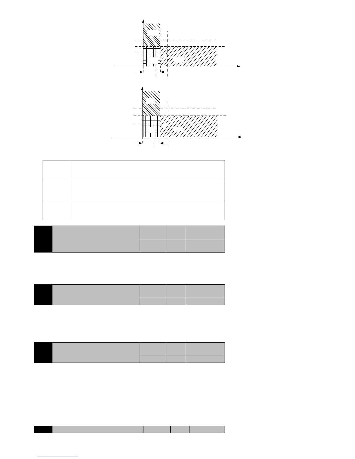
91
Time/s
P8-17
Speed/rpm
0
movement②
Area
D
P8-16
movement①
Actual speed②
Actual speed①
Area
B
R
Area
C
Area
A
Time /s
P8-17
Speed/rpm
0
movement②
Area
D
P8-16
movement①
Actual speed②
Actual speed①
Area
B
R
Area
C
Area
A
P8-15=0
Only in C and D regional S-ON is legal, that is,the time interval is greater
than P8-16, such as time ②, the figure in time ①can not be S-ON
successful.
P8-15=1
Only in B and C regional S-ON is legal, that is, the actual speed reduced to
less than P8-17, such as the actual speed ①, the figure in speed②can not be
S-ON successful.
P8-15=2
Only in C regional S-ON Is legal, that is ,not only time intervals is greater
than P8-16,but also the actual speed should be less than P8-17, at the same
time can be S-ON successful,such as R point.
P8-18
Braking resistance setting
Initail value
Unit
Communication
Address
50(different
models)
Ω
2812H
Control Mode:P S T
Range:10~750
Data size:16bit
Display mode:Decimal system
Parameter function:Setting the braking resistor, when using the built-in braking resistor please do not modify.
P8-19
Braking resistor power setting
Initail value
Unit
Communication
Address
100 W 2813H
Control Mode:P S T
Range:30~3000
Data size:16bit
Display mode:Decimal system
Parameter function:Setting the braking resistor power, when using the built-in braking resistor please do not modify.
P8-20
Brake discharge duty ratio
Initail value
Unit
Communication
Address
50 - 2814H
Control Mode:P S T
Range:0~100
Data size:16bit
Display mode:Decimal system
Parameter function:when braking, duty ratio of opening brake pipe
When P8-20 is set to 100, duty ratio is 100% , that is , during braking the brake pipe fully opens;
When P8-20 is set to 0, duty ratio is 0%, that is, during braking the brake pipe is completely closed.
When P8-20 is set to 0, duty ratio is 0%, that is, during braking the brake pipe is completely closed.
7.9 Pb-xx the origin of regression function parameters
Pb-00
alarm time of failure back to zero
Initail
Unit
Communicatio
Page 92
92
value
n Address
0
ms
2B00H
Control Mode:P S T
Range:0~65535
Data size:16bit
Display mode:Decimal system
Parameter function: When receive the instruction of the origin of regression , if in this parameter‘s setting time,it fails to locate the origin,then
the drive appears AL01C and alarm, ALM terminal will act.
This parameter is set to 0, close monitoring of the origin of regression, and it is not alarm even the origin of regression fails.
Note: It is recommended to set Pb-00 to a appropriate time, and avoid false alarms when
performing a long time.
Pb-01
Origin triggered start mode:
0: Disable origin of regression function
1: The servo can enable automatic execution
after origin of regression
2: from SHOM function terminal (function
23) triggered the original Point return.
Initail
value
Unit
Communicatio
n Address
0 - 2B01H
Control Mode:P S T
Range:0~2
Data size:16bit
Display mode:Decimal system
Parameter function:Choose Start mode of origin of regression function
Pb-01=0:Do not use of origin of regression function.
Pb-01=1:Servo drive when power is first, once the servo enable (S-ON), automatically and immediately homing.
Pb-01=2:That being defined as SHOM of origin of regression make DI terminal (function 23) can be effective when
immediately Start homing. Even when the SHOM unfinished terminal is invalid, we can not suspend the execution of the of
origin of regression.
Note: SHOM terminals are level triggered. If the origin of return is completed at the
terminal is still valid, it will perform the origin of regression again.
Pb-02
Move a short distance to reach the origin of
ways:
0: after finding the origin point Reference, the
motor folded in 2nd speed to find the nearest
degree Z-phase pulse as the mechanical
origin.
1: after find reference point, the motor
continues to move in the same direction
in 2nd speed to find the nearest Z-phase pulse
as Mechanical origin.
2: According to Pb-03 settings.
Initail
value
Unit
Communicatio
n Address
0 - 2B02H
Control Mode:P S T
Range:0~2
Data size:16bit
Display mode:Decimal system
Parameter function:Setting short distance moves when arriving near the origin:
Pb-02=0:after finding the origin point Reference, the motor folded in 2nd speed to find the nearest degree Z-phase pulse as the
mechanical origin.
Pb-02=1:after find reference point, the motor continues to move in the same direction in 2nd speed to find the nearest Z-phase
pulse as Mechanical origin.
Pb-02=2:According to Pb-03 settings.
When Pb-03=0 or 1, the forward reverse limit CCWL (prohibit the positive driver of the terminal P-OT, function number 13) or CWL
(prohibit reverse drive terminal N-OT, function number 14) immediate deceleration stop.
If Pb-03=2 or 3, find the rising edge of the detector ORGP as a mechanical origin.
If Pb-03=4 or 5, find the first Z pulse rising edge as the mechanical origin.
Pb-03
origin detector type and Looking direction
setting:
0: Forward direction to fing the origin point,
and with P-OT signal Input point as a rough
reference point of origin.
1: Reverse direction to find the origin point,
and with N-OT signal Input point as a rough
reference point of origin.
2: Forward direction to fing the origin point,,
and terminal ORGP signal (function 22) as
the origin point of reference.
3: Reverse direction to fing the origin point,,
Initail
value
Unit
Communicatio
n Address
0 - 2B03H
Page 93

93
and terminal ORGP signal (function 22) as
the origin point of reference.
4: Forward direction to directly find origin of
Z-phase pulse
5: Reverse direction to directly find origin of
Z-phase pulse
Control Mode:P S T
Range:0~5
Data size:16bit
Display mode:Decimal system
Parameter function:Setting origin detector type and looking direction:
Pb-03=0:Forward direction looking for the origin, and make the CCWL limit point of input (prohibit the forward drive terminal P-OT,
function number 13) as the origin of the rough reference point. When the completion of the origin location, CCWL is converted to prohibit
forward drive function, and then the re-trigger will produce limit warning. When this method is used, the limit input point as the origin of
the rough reference point, it is recommended to set the return to find the Z pulse (Pb-02=0) as a precision machine origin.
Pb-03=1:Reverse direction looking for the origin, and make the CWL limit point of input (prohibit reverse drive terminal S-OT, function
number 14) as the origin of the rough reference point. After the completion of the origin positioning, CWL is turned to prohibit the reverse
function, and then the trigger will produce a limit warning. When using this method, the limit input point as the origin of the rough
reference point, it is recommended to set the return to find the Z pulse (Pb-02=0) as a precise mechanical origin.
Pb-03=2:Forward direction looking for the origin, and make ORGP (input point of external detector, DI function number 22) as reference
point of the origin. At this time, the exact mechanical origin can be set to return to search (Pb-02=0) or not to return to find (Pb-02=1) Z
phase pulse. When the Z phase pulse is not used as the mechanical origin, the positive edge of ORGP can be set to the mechanical origin
(Pb-02=2).
Pb-03=3:Reverse direction to find the origin, and make ORGP (external detector input point, DI function number 22) as reference point of
the origin. At this time the exact mechanical origin can be set to return to search (Pb-02=0) or not to return to find (Pb-02=1) Z phase pulse.
When the Z phase pulse is not used as the mechanical origin, the positive edge of ORGP can be set to the mechanical origin (Pb-02=2).
Pb-03=4:Forward direction direct search for the rising edge of the Z phase pulse as the origin, this approach is usually used for the load for
the occasion of rotary motion, at this time can‘t externally connected any detecting switch.
Pb-03=5:Reverse direction direct search for the rising edge of the Z phase pulse as the origin, this approach is usually used for the load for
the occasion of rotary motion, at this time can‘t externally connected any detecting switch.
Pb-04
back to zero the first high speed setting
Initail
value
Unit
Communicatio
n Address
500
rpm
2B04H
Control Mode:P S T
Range:0~3000
Data size:16bit
Display mode:Decimal system
Parameter function:when implement the origin of regression function, the motor speed before reaching the reference point .
Pb-05
back to zero the second low speed setting
Initail
value
Unit
Communicatio
n Address
50
rpm
2B05H
Control Mode:P S T
Range:0~1000
Data size:16bit
Display mode:Decimal system
Parameter function: when implement the origin of regression function, after reaching the reference point, the motor speed of final positioning
to the origin point.
This rate should not be set too high, orwhen the load inertia is large ,it may occur overshoot.
Pb-06
High 5 position of the origin of regression
Offset Pulse Number
Initail
value
Unit
Communication
Address
0
rev
2B06H
Pb-07
Low 4 position of the origin of regression
Offset Pulse Number
Initail
value
Unit
Communication
Address
0
ppr
2B07H
Control Mode:P S T
Range:Pb-06:-30000~+30000;Pb-07:-9999~+9999
Data size:16bit
Display mode:Decimal system
Parameter function:when implement the origin of regression function, If you want the motor‘s stop position and the reference point have
pulses offset, the Pb-06 and Pb-07 set the offset:
The formula is : offset =10000* Pb-06 +Pb-07
Be sure to pay attention to the calculation, Pb-06 and Pb-07 were signed.
example:
When Pb-06 is 612,Pb-07 is 0302,then the setting offset is +6120302。
When Pb-06 is -2,Pb-07 is 0000,then the setting offset is-20000。
When b-06 is 13,Pb-07 is 1050,then the setting offset is+131050。
Page 94
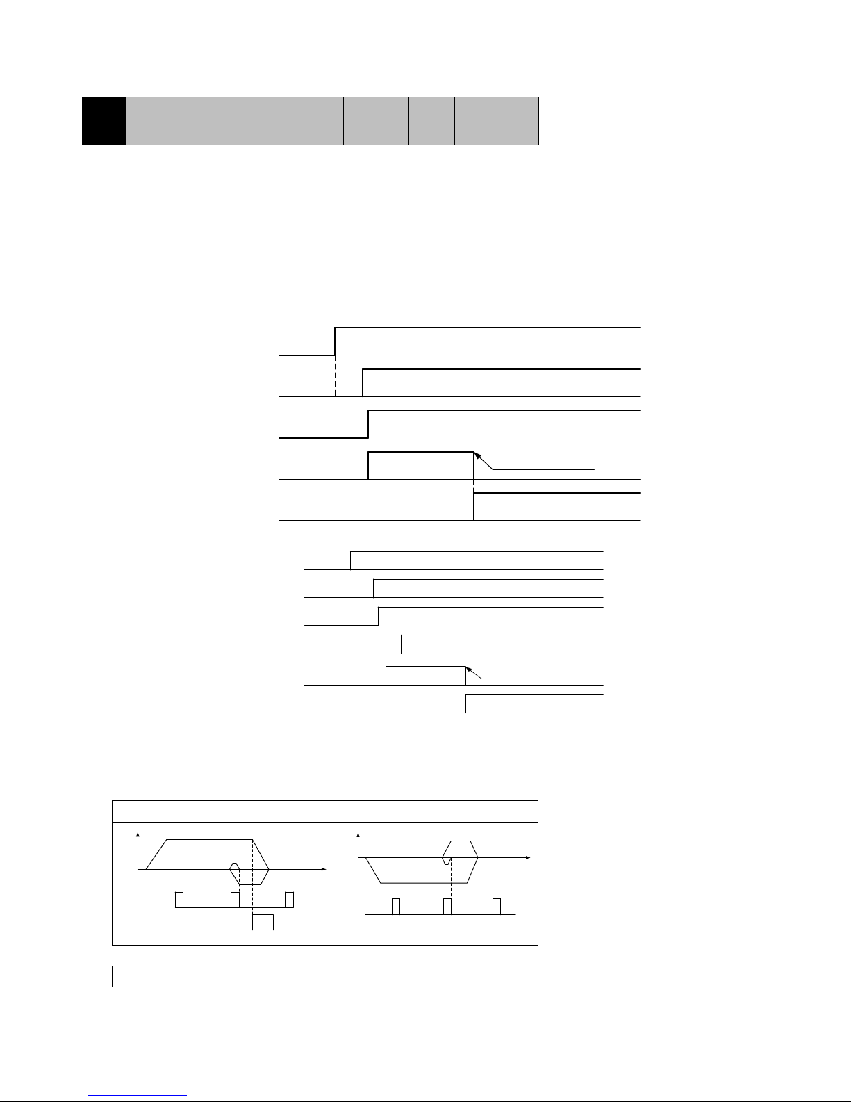
94
When Pb-06 is 13,Pb-07 is -1050,then the setting offset is+128950。
When Pb-06 is -13,Pb-07 is -1050,then the setting offset is-131050。
When Pb-06 is -13,Pb-07 is 1050,then the setting offset is-128950。
Pb-08
Whether to clear the position deviation
after the origin of regression is completed
Initail
value
Unit
Communicatio
n Address
0 - 2B08H
Control Mode:P S T
Range:0~1
Data size:16bit
Display mode:Decimal system
Parameter function:Whether to clear the position deviation after the origin of regression is completed
Pb-08=0:No clear position deviation.
Pb-08=1: clear position deviation.
Origin regression time sequence diagram:
(a): The origin regression to trigger the start mode time sequence diagram
1: On power, servo enable after the automatic implementation of the origin regression
(Pb-01=1)
Power supply
Servo prepared
Servo enable
Origin regression
HOME terminal
The maximum execution
time is limited to Pb-00
Origin of
execution
ON
ON
ON
effective
2: The origin regression (Pb-01=2) is triggered by the SHOM functional terminal (function number 23).
Power Supply
Servo prepared
Servo enable
Origin regression
HOME terminal
The maximum execution
time is limited to Pb-00
Origin of
execution
ON
ON
ON
effective
SHOM terminal
ON
After the completion of the origin of the return, is defined as the HOME (function number 14) of the output terminal that is the output of the
effective signal. If the origin of the regression process, cancel the servo enable or alarm, the regression function will be suspended and the
HOME terminal does not output effective signal.
(b):Speed displacement time sequence diagram of origin regression
1: Pb-02=0,Pb-03=0 or 2
2: Pb-02=0,Pb-03=1 or 3
Z pulse
position
Motor
speed
ORPG/P-OT
signal
Z pulse
position
Motor
speed
ORPG/N-OT
signal
3: Pb-02=1,Pb-03=2
4: Pb-02=1,Pb-03=3
Page 95
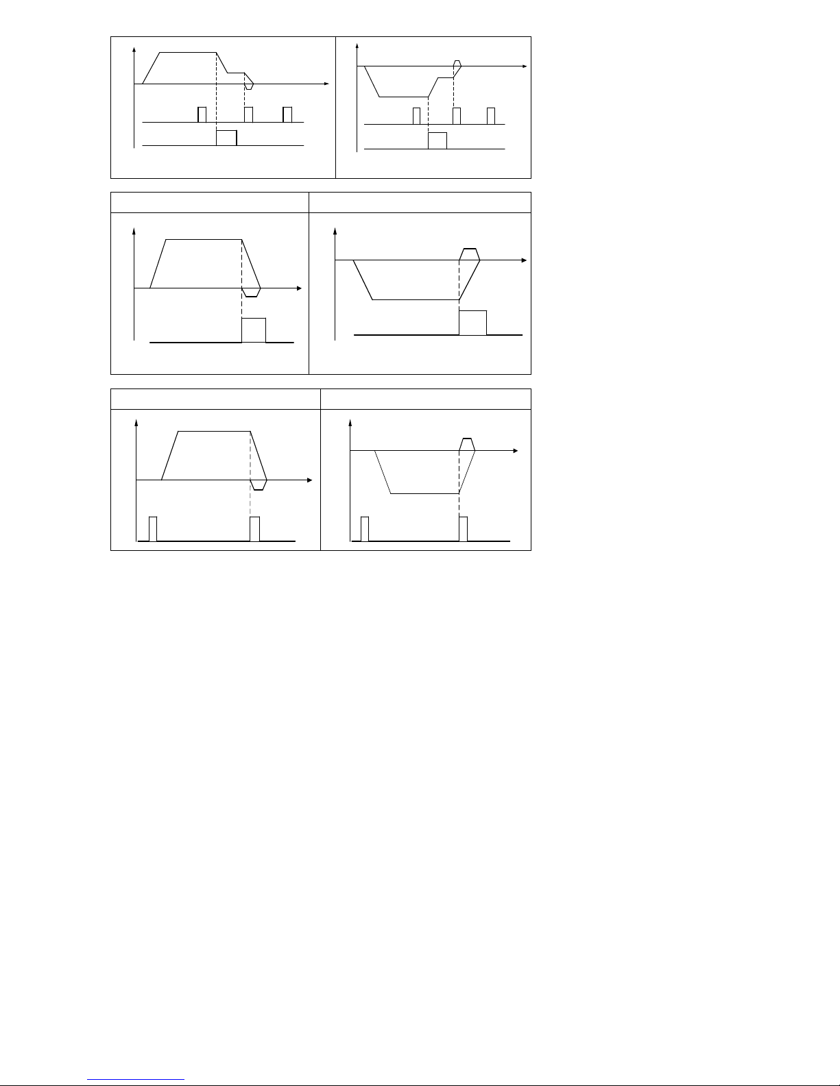
95
Z pulse
position
Motor
speed
ORPG signal
Z pulse
position
Motor
speed
ORPG signal
5: Pb-02=2,Pb-03=2
6: Pb-02=2,Pb-03=3
position
Motor
speed
ORPG
signal
position
Motor
speed
ORPG
signal
7: Pb-02=2,Pb-03=4
8: Pb-02=2,Pb-03=5
Z pulse
position
Motor
speed
Z pulse
position
Motor
speed
Page 96
96
8 Communications protocol
8.1 Application Scope
Applicable series: EA100
Applicable network: Support Modbus protocol, RTU format, RS485 bus.
The typical RTU message frame format:
Start Bit
Device Address
Function Code
Data
CRC
Stop Bit
T1-T2-T3-T4
8Bit
8Bit
n*8Bit
16Bit
T1-T2-T3-T4
8.2 Physical interface
RS485 asynchronous half duplex communication mode
RS485 terminal default data format:1-8-N-1, baud rate:9600bps
Data format: 1-8-N-1/2, 1-8-O-1/2, 1-8-E-1/2, baud rate 4800bps, 9600bps, 19200bps, 38400bps, 57600bps optional, can be set by the
function code P7-01 and P7-02
8.3 Protocol format
CRC Parity
Initial Block of
Frame ≥Idle
Periods of 4 Bits
Address of
Slave
Command
Code
Data
Stop Block of
Frame≥ Idle
Periods of 4 Bits
ADU
Figure 1 protocol format
The parity in ADU (Application Data Unit) is obtained via the CRC16 parity of the 1st three parts of ADU and switching the low bytes and high
bytes. Low bytes of CRC parity go first, and high bytes of it follow in the protocol format.
8.4 Command interpretation
Command code 0x03: Read parameter and status of servo drive.
ADU Item
Byte No.
Range
Master requests:
Address of slave
1
0-0FEH
Command code
1
0x03
Register start address
2
0x0000-0x0FFFF
Register number
2
0x0000-0x0008
CRC parity(Low bytes go first)
2
Slave responds:
Address of slave
1
Servo drive address
Command code
1
0x03
Byte length
1
2* Register number
Register data
2* Register number
CRC parity 2
Command code 0x06: write servo drive single function code or control parameters
ADU Item
Byte No.
Range
Master requests:
Address of slave
1
0-0FEH
Command code
1
0x06
Byte length
2
0x0000-0x0FFFF
Register data
2
0x0000-0x0FFFF
CRC parity 2
Slave responds:
Address of slave
1
Local address
Command code
1
0x06
Read bytes
2
0x0000-0x0FFFF
Register data
2
0x0000-0x0FFFF
CRC parity 2
Command code 0x10: rewrite the servo drive multiple function code or control parameters
ADU Item
Byte No.
Range
Host send request:
Address of slave
1
0-0FEH
Command code
1
0x10
Register start address
2
0x0000-0x0FFFF
Register number
2
0x0000-0x0008
Byte length of register data
1
2* Register number
Register data
2* Register number
Page 97
97
CRC parity 2
Slave responds:
Slave address
1
Local address
command code
1
0x10
Read bytes
2
0x0000-0x0FFFF
Register data
2
0x0000-0x0008
CRC parity 2
Command code 0x08: line diagnostics and settings
ADU Item
Byte No.
Range
Master requests:
Address of slave
1
0-0FEH
Command code
1
0x08
Sub function code
2
0x0000-0x0FFFF
data
2
CRC parity 2
Slave responds:
Address of slave
1
Local address
Command code
1
0x08
Sub function code
2
0x0000-0x0FFFF
data
2
CRC parity 2
Note: the 0x08 command code is only used to check whether the line is connected.
8.5 Protocol Format Description
Address code
Servo drives slave address. The Setting range: 1-247.
Function code
Function code
Function describe
03H
Read parameters and status byte of servo drive
06H
Write single function code or control parameter of servo drive
10H
Write several function codes or control parameters of servo drive
08H
Circuit diagnosis and setting
Allocation of Register Addresses
Name
Address Space
Description
Function
Code
0000H-0FxxH
High byte is function code group number, and high byte
address corresponding to P0-PF is 00H-0FH. And low byte is
group internal function code number.
For example: P3-00 corresponds to the address of 0300H.
2000H-2FxxH
If you want to save the modified parameters, which means to
modify the contents of the EEPROM, adding 2000H to
functional code address is OK.
For example: P3-00 corresponds to the address of 2300H
Remark
*: Some function parameters have two communication addresses, such as P1-00 have two communication addresses: 0100H and 2100H.
Beginning with address 0, it indicates that this parameter written to the RAM register of the drive, and can be executed immediately, but will not
be saved; Beginning with address 2, it indicates that this parameter written to the EEPROM of drive, can be executed immediately and saved;
*: If you require to frequently rewrite parameters frequently to EEPROM, due to the limit of writing cycles of EEPROM, EEPROM may be
damaged. Therefore, for parameters which need to be frequently rewritten via communication, please use RAM address, whose starting address
is 0. For example, in speed mode, when it need to transfer speed command in real time via the communication, the written address of speed
command must use 0300H, not 2300H.
*: For the parameters whose RAM register addresses are not listed, when using the address
starting with 0, the data will be received but will not be executed and saved. When these
parameters using EEPROM address, the data will be saved, but whether executed
immediately depend on parameter attributes.
CRC Parity
Sending equipment calculates CRC parity value first, and then attaches it to the sending message. Upon receipt of the message, receiving
equipment will calculate CRC parity value again, and compare the operation result with received CRC parity value. If the two values are
different, it indicates that there is error during transmission.
Calculation process of CRC parity:
1) Define a CRC parity register, and initialize it as FFFFH.
2) Conduct XOR calculation between the 1st byte of sending message and the value of CRC parity register, and then upload the result to
CRC parity register. Start from address code, the start bit and stop bit will not be calculated.
Page 98
98
3) Collect and check LSB (the least significant bit of CRC parity register).
4) Shift each bit of CRC parity register rightwards by 1 bit, the highest bit filled with 0.
5) If LSB is 1, conduct XOR calculation between the value of CRC register and A001H, and then upload the result to CRC parity register.
6) Repeat steps 3, 4 and 5 until completing 8 rounds of shifting.
7) Repeat steps 2, 3, 4, 5 and 6, and process the next byte of sending message. Repeat above process continuously until each byte of
sending message is processed.
8) CRC parity date will be saved in CRC parity register after calculation.
9) First send the low byte of CRC parity when sending, and then send the high byte.
Circuit diagnostics and 0x08 setting description
Sub-function
Code
Data Requested
Response Data
Indication of
Sub-function
0000H
#data16
The same as the data requested
Circuit Diagnosis
Abnormal response
When the host sends the wrong data or the servo error data caused by disturbance, it will send back an exception response. Abnormal response
data structure:
ADU Item
Byte count
Description
Address code
1
Address of slave
Function code
1
Equal to the function code of + 0x80
Exception code
1
See the exception code table
CRC parity (L) 2 CRC16
CRC parity (H)
CRC16
Abnormal table:
data
Meaning
01
CRC parity error
02
Function code is not correct
04
Send data length is not correct
08
Register address error
10
Register digital error
20
Register modification error
40
EEPROM busy
Note: if the function code is wrong, the exception code is 0x02
8.6 Example
Write 01 servo drive control mode for position control, that is, P1-00=1.
Sending sequence
0 1 2 3 4 5 6 7 8
9
Sending content
01H
06H
01H
00H
00H
01H
49H
F6H
Receive sequence
0 1 2 3 4 5 6 7 8
9
Receive content
01H
06H
01H
00H
00H
01H
49H
F6H
Page 99
99
9 Fault alarm and Treatment
9.1Fault Diagnosis and Treatment
When a fault or alarm occurs, the servo drive will display ―AL‖
Last fault can be viewed by P0-18. Fault display and treatment measures are as follows:
AL001:Short circuit
AL002:Hardware over current
AL003:Software over current
Fault Causes
Check
Solution
Short circuit of drive
output
1:Check the connection status between
motor and drive or if there is a short circuit
2:Check if the motor damaged
1: Exclude short circuit condition and
avoid metal conductor being exposed
externally.
2:Replace the damaged motor
Wiring error of the
motor
Check the wiring order of motor connected
to the drive
Re-wiring based on the wiring order
specification
Setting error of
control parameter
Check if the set value is much greater than
the factory setting value
Resume defaulted setting, and then
gradually modify
Command changes
drastically
Check if the control input command
changes too drastically
Fixed the change ratio of the input
command or initialize filter function
External braking
resistor is too small
or short circuit
Check if the external braking resistor
meets the specification
Use the braking resistor matched the
specification and set the parameters of
P8-18 and P8-20 correctly
Drive hardware fault
When all the above problems are excluded,
the fault still occurs
Send back to the dealer or the factory for
check
AL003:AD Initialization Fault
Fault Causes
Check
Solution
Fault of drive hardware
Power to restart,if the fault still occurs
Send back to the dealer or the factory for
check
AL004:Memory Error
Fault Causes
Check
Solution
Abnormal write of
parameter data
Power off and restart,if the fault still
exists
Replace the drive
Memory stored too
frequently
Check the program of upper computer if
the drive‘s EEPROM is frequently
written.
Modify the program of upper computer,
changed to RAM address in case it should
be frequently written.
AL006:AD Sampling Fault
Fault Causes
Check
Solution
External analog
sampling deviation is
too large or timeout in
conversion
Power off and restart,if the fault still exists
Send back to the dealer or the factory
for check
AL007:Encoder Error 1
Fault Causes
Check
Solution
Encoder is loose
Check CN5 on the drive and the connector of
encoder
Re-install
Encoder wiring error
Check if the encoder wiring follows the
recommended specification as mentioned in
the manual
Wiring correctly
Encoder connection not
good
Check if CN5 on drive is well connected to
servo motor encoder, and if the shielding
layer is intact
Re-wiring
Encoder damaged
Exclude wiring problems, the fault still exists
Replace the motor
AL008:Encoder Error 2
Fault Causes
Check
Solution
Z signal error of incremental
Same with AL007
Same with AL007
Page 100
100
encoder
CRC check error of absolute
encoder
AL009:Encoder Error 3
Fault Causes
Check
Solution
AB signal error of incremental
encoder
Same with AL007
Same with AL007
Communication error of
absolute encoder
AL00A:Under voltage
Fault Causes
Check
Solution
Main circuit input voltage is
lower than the rated voltage
value allowed
Check if input voltage and the
wiring are normal
Check the mains supply
No voltage on the input side of
the mains circuit
Check if the main circuit voltage is
normal
Check the power supply switch
Power supply error
Check if the power is consistent
with the specification
Use the correct power supply
AL00B:Overvoltage
Fault Causes
Check
Solution
Main circuit input voltage is
higher than the rated voltage
allowed
Check if the main circuit voltage is in
the allowable range
Use the correct power supply
Power input error
Check if the power is consistent with
the specification
Use the correct power supply
Motor decelerates too fast
Check if the system inertia is too large
and decelerates too fast
Increase the deceleration time, or use a
suitable external braking resistor
Drive hardware fault
Measuring the main circuit voltage is
in the allowable range, and the fault
still occurs when the motor is not
running
Send back to the dealer or the factory for
check
AL00D / AL00E:Motor Overload / Drive Overload
Fault Causes
Check
Solution
Continuous use above the
rated load
1:Monitor P0-01 if it is continuously
more than 100%
2:Monitor P0-12 if it is continuously
more than the rated value
1:Increase motor capacity or reduce load
2:Increase drive capacity or reduce load
Motor, encoder wiring error
Check the U, V, W and encoder wiring
Correct wiring
Set control parameter
improperly
1: if mechanical oscillates and the
motor sounds abnormally
2:Acceleration and deceleration are
too fast
1: Adjust the position, velocity gain
value
2:Reduce acceleration and deceleration
time
Drive or motor fault
Exclude above problems
Send back to the dealer or the factory for
check
AL010:Drive Overheat
Fault Causes
Check
Solution
Ambient temperature is too
high
Check if the ambient temperature and
humidity are in the permitted range
Improve the installation environment
Cooling fan of the drive is
damaged
Check if the cooling fan is running
during operation
Replace the fan which is not running
The cooling of servo drive is
affected
1 : Check if the drive installation
follows the requirements
2:Check if the drive‘s heat sink is
blocked
1: Install the drive properly, refer to
Chapter II
2:Clean up the blockage
AL012:Overspeed
Fault Causes
Check
Solution
UVW phase sequence error
Check if the phase sequence of UVW
is correct
Wiring as per correct phase sequence
 Loading...