

Page 1
SERVICE MANUAL
CASSETTE, FLOOR&CEILING, DUCT UNITS
DC INVERTER
SERIES
OUTDOOR UNITS
OUTDOOR AND INDOOR UNITS
Page 2
8. Refrigeration System Principles
Refrigeration Cycle: The low-temperature and low-pressure refrigerant vapour in the evaporator is
compressed into high-temperature and high-pressure gas by the compressor, and then the gas enters
into condenser.The gas becomes high-temperature and high-pressure liquid through heat exchange with
outdoor air, and then the liquid passes through the capillary for cooling and decompression by throttling
and enters into evaporator.After that, the gas-liquid refrigerant in the envopator is completely evaporated
to cool the indoor air.The vapour out of the evaporator is re-compressed by the compressor. So is the
above procedure recycled that the cooled air in the duct is contiuously sent to air-conditioning area with
the help of fan motor.
Heating Cycle: It is
reverse to cooling cycleDŽIn this case, 4-way valve will reverse and flow direction of
refrigerant changes, i.e the vapour out of the compressor enters into heat exchanger for condensation.
The refrigerant after condensation passes through the capillary for throttling.After that it evaporates in
the outdoor heat exchanger, at last it will be sucked and compressed by compressor. So is the above
procedure recycled that the hot air in the duct is contiuously sent to air-conditioning area with the help of
fan motor.
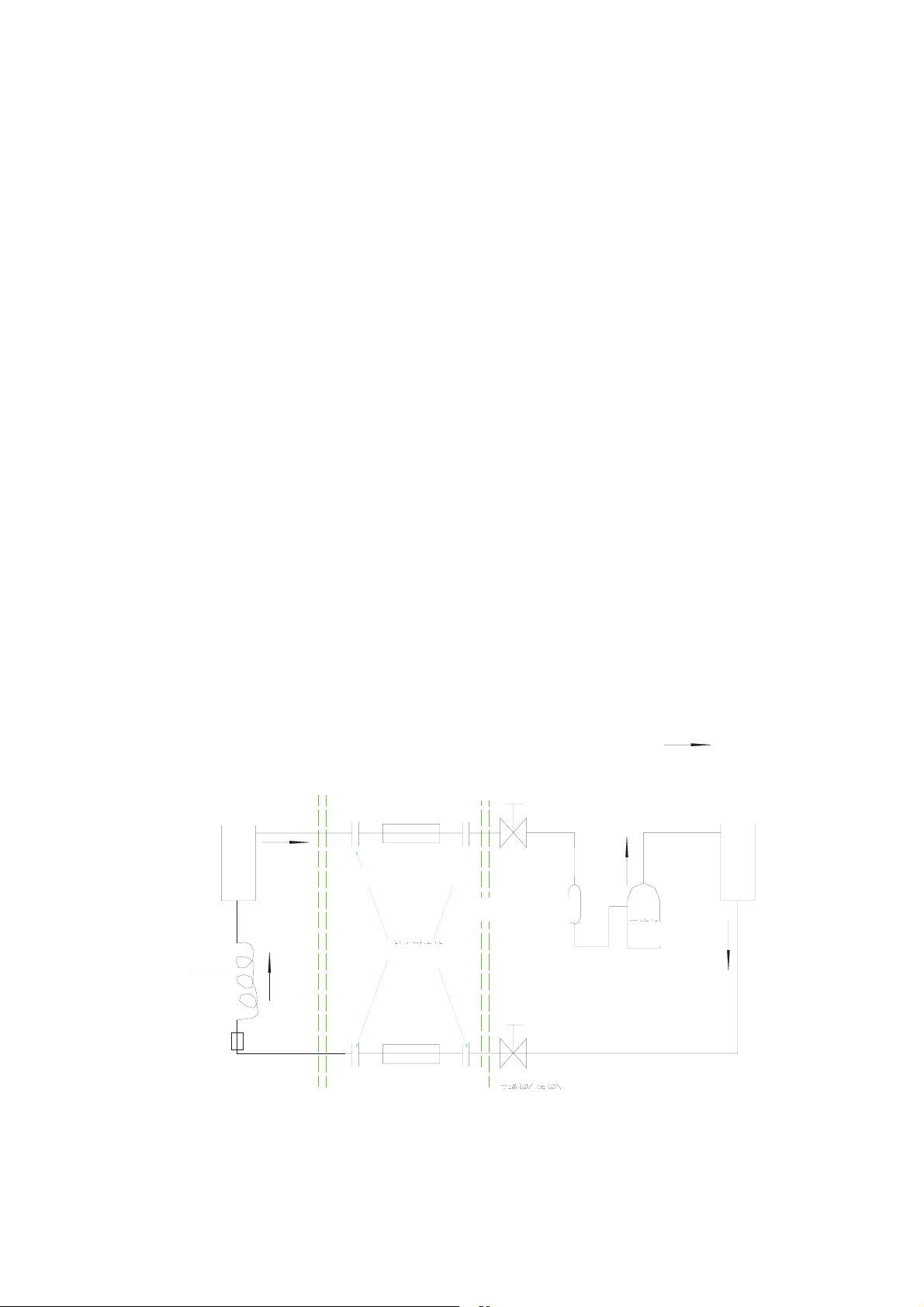
Working Principle of the Unit:
Flow direction during cooling
Flow direction during heating
3-way Valve (gas valve)
Outdoor Unit
Indoor Unit
Connection pipe
(with insulating tube)
Gas-liquid separator
Compressor
Flare joint
Main Capillary
Connection pipe
(with insulating tube)
3-way Valve (liquidvalve)
(a) Working principle of cooling only unit
27
Page 3

(b) Working principle of heat pump unit
Fig. 6-1
Flow direction during cooling
Flow direction during heating
3-way Valve (gas valve)
Indoor Unit 4-way Valve Outdoor Unit
Connection pipe
(with insulating tube)
Gas-liquid separator
Comp-
Flare joint
ressor
Main Capillary
A
uxiliary Capillary
Filter
Connection pipe
One-way Valve
3-way Valve (liquidvalve)
(with insulating tube)
28
Page 4

Chapter II Control Functions
1. Control Mode
The 4-in-1 DC Inverter Unit consists of outdoor mainboard, indoor mainboard and manual
controller, which are lined via communication wires. In this way, one outdoor unit can be used with
different indoor units of the equal capacity (duct type unit, floor ceiling unit, cassette type unit and
ceiling type unit), and the cooling and heating share one electronic expansion valve.
The outdoor compressor is DC inverter compressor, in which the advance
d sine wave control
mode is used, featuring in low vibration, low noise and high efficiency. The single-phase unit also
uses the PFC control, with PFC value up to 0.99 or higher, so the interference to the electric grid
is very low.
The outdoor unit also applies the advanced PI algorithm, able to
automatically and quickly adjust
the working frequency of the compressor according to the change of indoor loads. This can not
only meet the user’s requirements for comfort but also save unnecessary electric energies.
This unit can be controlled via LCD controller easily or controlled fr
om remote controller. It can
also be controlled from centralized controller, or put under remote monitor by PC computer.
Besides, it can also be configured with weekly timer wired controller which can automatically
switch on or off the unit at predefined time for each day in a week. This is suitable to family, office,
factory and man-free places.
2 Introduction Control Functions
2.1 Basic Control Functions
2.1.1 Cooling Mode
After setting to cooling mode, the indoor fan will
run at preset speed after 3 seconds and the
outdoor unit will start to calculate the system load demand. If the load is “0”, the other loads
except the indoor fan and indoor drainage pump will not be put into operation. If the load is over
“0”, the electronic expansion valve will be firstly opened and then the outdoor fan is started. After
30 seconds, the compressor is started.
Under cooling mode the range of temperature setting is 16~30
and the initial value is 26.
2.1.2 DRY Mode
The DRY mode is basically same as the cooling mode. The dif
ference is that: The speed of
indoor fan is fixed at low speed; and The maximum value of capacity output is 90%.
°C
°C °C
29
Page 5

Under DRY mode, the range of temperature setting is 16°C~30°C and the initial value is 24°C.
2.1.3 Heating Mode
After setting to heating mode, the outdoor unit will st
art to calculate the system load demand. If
the load is “0”, all the other loads will not be put into operation. If the load is over “0”, the electronic
expansion valve will be firstly opened and then the outdoor fan is started. After 30 seconds, the
compressor is started, the 4-way valve is energized and the indoor fan runs under anti cold air
mode.
Under DRY mode, the range of temperature setting is 16°C~30°C and the ini
tial value is 20°C.
2.1.4 Fan Mode
When the indoor unit is set to fan mode, all the loads of the out
door unit will be stopped and the
indoor fan will run at preset speed. Under this mode, the fault is detected but will not be treated.
The temperature is not adjustable, displayed at 26°
C.
2.1.5 Auto Mode
Under this mode, the run mode will vary with the ambient temper
ature according to the following
conditions:
When T
amb.
˚26°C, the unit will run under cooling mode and the preset temperature is 26°C;
When 20°CT
amb.
26°C, the unit will run under DRY mode and the preset temperature is 24°C;
When T
amb.
˘20°C, the unit will run under heating mode and the preset temperature is 20°C.
When T
amb.
24°C, the unit will exit the heating mode. For cooling-only unit, when T
amb.
˘20°C,
the unit will run under fan mode and the preset temperature is 20. When T
amb.
24°C, the unit will
exit the fan mode.
Once the mode is activated, the unit will run
30 seconds the shortest before it switch the run
status under auto mode according to the ambient temperature.
2.2 Special Control Functions
2.2.1 Energy-saving Func
tion
Set a upper and lower limit of temperature by using manual controlle
r, so that the temperature of
air conditioner is set to an energy-saving range, thus to save the power consumption of the air
conditioner. For example, the temperature under cooling mode is defaulted 1630°C, but the
user may customize it to 2630°C by using manual controller. In this range, the lowest setting is
26°C other 16°C.
2.2.2 Memory Function
Upon re-energization after power shutdown or failure, the air conditioner can
memorize the last
work mode, temperature setting, fan speed and other parameters, so that it is not necessary to
repeat setting of those parameters. The user may also inactivate this function by using manual
controller.
2.2.3 Timer Function
For easy control of the air conditioner, the user may set the air conditione
r to timer on or timer off
by using the manual controller. The timer is available with two modes for user’s option, i.e.
countdown and 7-day time section.
30
Page 6

2.2.4 Sleep Function
If the user requires air conditioner during sleep, this function may automatically increase or
decrease the preset temperature, so as to meet the users’ needs for comfort and also save the
energy. If used with timer function, the energy saving effect will be better.
2.2.5 Alarm Function
When the air conditioner is abnormal, it can automatically display the faul
t or protection type,
while triggering the sound and lighting alarm.
2.2.6 Week Timer Centralized Control Function
The user may select centralized controller to control 16 units simultaneously for their start/stop,
timer on/of
f each day and key shield. The function is powerful, particularly suitable to
long-distance air conditioner system with many units.
2.2.7 Remote Monitor Function
By selecting the remote monitor function, the user may mo
nitor the working parameters and
control the run mode of the air conditioner from a family PC. This is suitable to centralized control
of air conditioners in hotel, restaurants and factory. Up to 254 sets of units may be monitored
simultaneously.
2.2.8 Fresh Air Function (Duct
Type Unit)
This function is suitable to duct type unit and help
ful to introduce outdoor fresh air and enhance
the user’s comfort during use of the air conditioner. It is a truly air conditioning system.
2.2.9 Drainage Function (Duct Type Unit)
This function is suitable to duct type unit and help
ful to extend the applications of the air
conditioner. By this function, the installation of air conditioner will no longer be restricted.
2.2.10 Air Valve Control Function (Duct
Type Unit)
This function is suitable to duct type unit. By this
function, the unit may be connected to 8 air valve
controllers. The fan speed is controlled by controlling the number of air valves that will be opened
or closed, thus to meet the needs of each room for air flow.
31
 Loading...