

Page 1

MULTI VARIABLE SERIES
CASSETTE
MV-CxxBI
SERVICE MANUAL
EN
Page 2

“Originalinstructions”
IMPO
RTANT N
OTE:
Read this manual ca
r
efully befo
r
e installing
or operating your new air conditioning
unit. Make sure to save this manual for
futu
re r
efe
r
ence.
Page 3

Service Manual
Table of Contents
Part
Ⅰ
: Technical Information
.......................................................................1
1. Summary
......................................................................................................................1
2. Specications
..........................................................................................................2
2.1 Specication Sheet ...........................................................................................................2
3. Outline Dimension Diagram
........................................................................5
4. Refrigerant System Diagram
......................................................................6
5. Electrical Part
...........................................................................................................7
5.1 Wiring Diagram .................................................................................................................7
5.2 PCB Printed Diagram .......................................................................................................9
6. Function and Control
......................................................................................10
6.1 Remote Controller Introduction .....................................................................................10
6.2 Brief Description of Modes and Functions ......................................................................14
Part
Ⅱ
: Installation and Maintenance
.................................................17
7. Notes for Installation and Maintenance
..........................................17
8. Installation
................................................................................................................20
8.1 Installation Dimension Diagram ......................................................................................20
8.2 Installation of Cassette Type ..........................................................................................21
8.2 Installation of Cassette Type ..........................................................................................21
9. Maintenance
............................................................................................................23
9.1 Error Code List ...............................................................................................................23
9.2 Troubleshooting for Main Malfunction ............................................................................24
9.3 Maintenance Method for Normal Malfunction .................................................................30
10. Exploded View and Parts List
..............................................................32
11. Removal Procedure
.......................................................................................38
Page 4

Service Manual
Appendix:
........................................................................................................................42
Appendix 1: Reference Sheet of Celsius and Fahrenheit ....................................................42
Appendix 2: Conguration of Connection Pipe .....................................................................42
Appendix 3: Pipe Expanding Method ...................................................................................43
Appendix 4: List of Resistance for Temperature Sensor ......................................................44
Page 5

1
Service Manual
1. Summary
Part
Ⅰ
: Technical Information
Indoor Unit
MV-C12BI
MV-C18BI
MV-C24BI
Remote Controller
YT1F(MOTO)
Page 6

2
Service Manual
Parameter Unit Value
Model MV-C12BI MV-C18BI
Product Code CN510N0120 CN510N0130
Power
Supply
Rated Voltage V~ 220-240 220-240
Rated Frequency Hz 50 50
Phases 1 1
Cooling Capacity KW 3.50 4.50
Heating Capacity KW 4.00 5.0
Air ow volume(SH/H/M/L/SL) m
3
/h 650/560/520/450/- 710/670/590/450/-
Dehumidifying Volume L/h 1.4 1.8
Fan Type Centrifugal Centrifugal
Fan Diameter-height mm Φ322–148 Φ322–148
Fan Motor Cooling Speed(SH/H/M/L/SL) rpm 800/700/650/560/- 900/850/750/580/Fan Motor Heating Speed(SH/H/M/L/SL) rpm 800/700/650/580/- 900/850/750/600/Fan Motor Power Output W 45 45
Fan motor running current A / /
Fan Motor Capacitor μF / /
Evaporator Material Aluminum n-copper tube Aluminum n-copper tube
Evaporator Pipe Diameter mm Φ7 Φ7
Evaporator Number of Rows-Fin Pitch mm 2-1.4 2-1.4
Evaporator Length(L)XHeight(H)XWidth(W) mm 1320X190.5X25.4 1320X190.5X25.4
Fuse Current A 5 5
Sound Pressure Level(SH/H/M/L/SL) dB (A) 44/41/38/34/- 47/45/41/35/-
Sound Power Level(SH/H/M/L/SL) dB (A) 55/52/49/45/- 58/56/52/46/-
Dimension of Outline(LXWXH) mm 596X596X240 596X596X240
Dimension of Carton Box(LXWXH) mm 775X735X285 775X735X285
Dimension of Package(LXWXH) mm 778X738X300 778X738X300
Net Weight kg 20 20
Gross Weight kg 24 24
Liquid pipe mm Φ6 Φ6
Gas Pipe(to indoor unit) mm Φ9.52 Φ12
2. Specications
2.1 Specication Sheet
The above data is subject to change without notice. Please refer to the nameplate of the unit.
Page 7
3
Service Manual
Parameter Unit Value
Model
MV-C24BI
Product Code CN510N0140
Power
Supply
Rated Voltage V~ 220-240
Rated Frequency Hz 50
Phases 1
Cooling Capacity KW 7.10
Heating Capacity KW 8.0
Air ow volume(SH/H/M/L/SL) m
3
/h 1280/1220/1100/880/-
Dehumidifying Volume L/h 2.5
Fan Type Centrifugal
Fan Diameter-height mm Φ450-142
Fan Motor Cooling Speed(SH/H/M/L/SL) rpm 650/620/560/450/Fan Motor Heating Speed(SH/H/M/L/SL) rpm 650/620/560/460/Fan Motor Power Output W 45
Fan motor running current A /
Fan Motor Capacitor μF /
Evaporator Material Aluminum n-copper tube
Evaporator Pipe Diameter mm Φ7
Evaporator Number of Rows-Fin Pitch mm 2-1.5
Evaporator Length(L)XHeight(H)XWidth(W) mm 1965X171.5X25.4
Fuse Current A 5
Sound Pressure Level(SH/H/M/L/SL) dB (A) 47/45/41/36/-
Sound Power Level(SH/H/M/L/SL) dB (A) 58/56/52/47/-
Dimension of Outline(LXWXH) mm 840X840X240
Dimension of Carton Box(LXWXH) mm 960X960X310
Dimension of Package(LXWXH) mm 963X963X325
Net Weight kg 26
Gross Weight kg 32
Liquid pipe mm Φ9.52
Gas Pipe(to indoor unit) mm Φ16
The above data is subject to change without notice. Please refer to the nameplate of the unit.
Page 8

4
Service Manual
Note: Nominal capacities are based on the follow conditions.
Mode Indoor ( ) Outdoor ( )
Cooling
DB:27 (80.6) DB:35(95)
WB:19(66.2)WB:24(75.2)
Heating
DB:20(68)DB:7(44.6)
WB:--(--)WB:6(42.8)
Piping
Length
5m
The air volume is measured at the relevant standard external static pressure.
Noise is tested in the semianechoic room, so it should be slightly higher in the actual operation due
to environmental change.
Page 9

5
Service Manual
Unit:mm
MV-C24BI
3. Outline Dimension Diagram
MV-C12BI, MV-C18BI
Item
Model
ABCDEFG
MV-C12BI
670 666 600 496 145 240 596
MV-C18BI
MV-C24BI
950 840 780 680 145 240 -
Page 10

6
Service Manual
4. Refrigerant System Diagram
Page 11
7
Service Manual
LURQVKHOOPRWRU
RQO\DSSOLHVWRWKH
1RWH0RWRUJURXQG
/
/
(/(&75,&%2;
3(
%1
%.
%8
$&/
&20287
%1
;7
1
1
78%(7(0352207(03
6(16256(1625
78%(
.
5220
$3φ35,17('&,5&8,7%2$5'
287'22581,7
%8
%.
<(*1
3803
7(50,1$/
%/2&.
.
0
:$7(53803
02725
:$7(5'7&7
/,48,'/(9(/
6:,7&+
<(*1
3(
-803
&$3
,1'22581,7
&200$18$/
$3
:,5('
&21752//(5
(9$325$725
<(*1
3(
',63 ',63
:+ :+
&1 &1
$3
',63/$<%2$5'
5(&(,9(5$1'
6:,1*8'
5'
6:,1*8'
:+
; ; ; ;
0 0 0 0
67(302725
; ;
; ;
3(
<(*1
0
'&02725
)$102725
3(
<(*1
3(
'225&
$3
'5<
&217$&7
;
237,21$/
0$*1(7,&
5,1*
5. Electrical Part
5.1 Wiring Diagram
● Indoor Unit
● Instruction
Symbol Symbol Color Symbol Symbol Color Symbol Name
WH White GN Green CAP Jumper cap
YE Yellow BN Brown COMP Compressor
RD Red BU Blue Grounding wire
YEGN Yellow/Green BK Black / /
VT Violet OG Orange / /
Note: Jumper cap is used to determine fan speed and the swing angle of horizontal lover for this model.
600007060110
MV-C12BI, MV-C18BI
Page 12
8
Service Manual
LURQVKHOOPRWRU
RQO\DSSOLHVWRWKH
1RWH0RWRUJURXQG
/
/
($57+3/$7(
3(
%1
%.
%8
$&/
&20287
%1
;7
1
1
78%(7(0352207(03
6(16256(1625
78%(
.
5220
$3φ35,17('&,5&8,7%2$5'
287'22581,7
%8
%.
<(*1
',63
3803
7(50,1$/
%/2&.
.
0
:$7(53803
02725
:$7(5'7&7
/,48,'/(9(/
6:,7&+
<(*1
3(
',63
:+ :+
&1 &1
$3
',63/$<%2$5'
5(&(,9(5$1'
6:,1*8'
5'
6:,1*8'
:+
; ; ; ;
0 0 0 0
67(302725
; ;
; ;
-803
&$3
,1'22581,7
&200$18$/
$3
:,5('
&21752//(5
'225&
$3
'5<
&217$&7
(9$325$725
<(*1
3(
;
237,21$/
(/(&75,&%2;
%27720
3(
<(*1
<(*1
3(
3(
<(*1
0
'&02725
)$102725
3(
<(*1
3(
0$*1(7,&
5,1*
600007060124
These circuit diagrams are subject to change without notice, please refer to the one supplied with the unit.
MV-C24BI
Page 13

9
Service Manual
5.2 PCB Printed Diagram
1
2
3
456789 10
12
11
13
16
1415
No. Name
1
Interface of fan
2
Interface of live wire
Fuse
3
4 Interface of netural wire
5
Air terminal
6
Terminal with outdoor unit
communication wire
7 Water pump control
8
Interface of ambient temperature sensor
9 Interface of tube temperature sensor
10 Water full detection terminal
12 Jumper cap terminal
Up&down swing motor
Display interface
11
14 Wired controller
1613Grounding wire
15 Interface of gate-control detection
● Top view
● Bottom view
Page 14

10
Service Manual
6. Function and Control
6.1 Remote Controller Introduction
Buttons on remote controller
Introduction for icons on display screen
7
2
1
8
10
12
15
14
13
11
9
6
5
4
3
1 ON/OFF button
2 MODE button
3 +/- button
4 FAN button
5 I FEEL button
11
X-FAN button
Note: X-FAN is the same with BLOW
12 TEMP button
13 TURBO button
15 LIGHT button
14 SLEEP button
10
TIMER ON/TIMER OFF
button
9 CLOCK button
Send signal
Turbo mode
X-fan mode
Set temperature
Set time
TIMER ON / TIMER OFF
Child lock
Up & down swing
Set fan speed
AIR function
I feel
Light
Temp. display type
:Set temp.
:Outdoor ambient temp.
:Indoor ambient temp.
Sleep mode
Clock
Health function
Heat mode
Fan mode
Dry mode
Cool mode
Auto mode
Operation mode
8 button
6 button
7 button
Introduction for buttons on remote controller
Note:
●
After putting through the power, the air conditioner will give out a sound. Operation indictor " " is ON (red indicator).
After that, you can operate the air conditioner by using remote controller.
ON/OFF button1.
Press this button can turn on or turn off the air conditioner. After turning on the air conditioner, operation indicator " "
on indoor unit’s display is ON (green indicator.The colour is different for different models), and indoor unit will give out a sound.
● This is a general use remote controller, it could be used for the air conditioners with multifunction; For some function,
which the model doesn't have, if press the corresponding button on the remote controller that the unit will keep the
original running status.
Page 15

11
Service Manual
● After selecting auto mode, air conditioner will operate automatically according to ambient temperature. Set temperature
can’t be adjusted and will not be displayed as well. Press "
FAN" button can adjust fan speed. Press " " button can adjust
fan blowing angle.
● After selecting cool mode, air conditioner will operate under cool mode. Cool indicator " "on indoor unit is ON. Press "+"
or "-" button to adjust set tempe rature. Press "FAN" button to adjust fan speed. Press " " button to adjust fan blowing a
ngle.
● When selecting dry mode, the air conditioner operates at low speed under dry mode. Dry indicator " " on indoor unit is ON
.
Under dry mode, fan speed can’t
be adjusted. Press " " button to adjust fan blowing angle.
● When selecting fan mode, the air conditioner will only blow fan, no cooling and no heating. All indicators are OFF. Operation
indicator is ON. Press
"FAN" button
to adjust fan speed. Press
● When selecting heating mode, the air conditioner operates under heat mode. Heat indicator " " on indoor unit is ON.
Press "+" or "-" button to adjust set temperature. Press "FAN" button to adjust fan speed.
Press " " button to adjust
fan blowing angle. (Cooling only unit won’t receive heating mode signal. If setting heat mode with remote controller,
press ON/OFF button can’t start up the unit).
Note:
● For preventing cold air, after starting up heating mode, indoor unit will delay 1~5minutes to blow air (actual delay time is
depend on indoor ambient temperature).
● Set temperature range from remote controller: 16~30
ć
; Fan speed: auto, low speed, medium speed, high speed.
MODE button2.
Press this button to select your required operation mode.
AUTOCOOL FANDRY HEAT
" " button to adjust fan blowing angle.
FAN button
I FEEL button
4.
5.
6.
7.
Pressing this button can set fan speed circularly as: auto (AUTO), low( ) ,medium
( ), high( ).
Note:
● Under AUTO Speed,IDU fan motor will adjust the fan speed (high, medium or
low speed) according to ambient temperature.
● Fan speed under dry mode is low speed.
Press this button to start I FEEL function and " " will be displayed on the remote controller. After this function is set, th
e remoteed
controller will send the detect ambient temperature to the controller and the unit will automatically adjust the indoor temper
ature
according to the detected temperature. Press this button again
to close I FEEL function and " " will disappear.
● Please put the remote controller near user when this function is set. Do not put the remote controller near the object of high
temperature or low temperature in order to avoid detecting inaccurate ambient temperature.
Press this button to set HEALTH function ON or OFF. After the unit is turned on, it defaults to HEALTH function ON.
Press this button to select AIR function ON or OFF.
button
button
(Only available for some models)
● This function is applicable to partial of models.
Auto
+/- button3.
● Press "+" or "-" button once increase or decrease set temperature 1ć.
Holding "+" or "-" button, 2s later
, set temperature
tor on indoor unit will change accordingly. (Temperature can’t be adjusted under auto mode)
● When setting TIMER ON, TIMER OFF or CLOCK, press "+" or "-" button to adjust time. (Refer to CLOCK, TIMER ON,
TIMER OFF buttons) When setting
TIMER ON, TIMER OFF or CLOCK, press "+" or "-" button to adjust time. (Refer
to CLOCK, TIMER ON, TIMER OFF buttons)
● When I FEEL function is turned on, the remote controller should be put within the area where indoor unit can receive the signal
sent by the remote controller.
on remote controller will
Page 16

12
Service Manual
Press this button to set clock time. " " icon on remote controller will blink. Press
"+" or "-" button within 5s to set clock time.
Each pressing of "+" or "-" button, clock time will increase or decrease 1 minute. If hold "+" or "-" button, 2s later, time will change
quickly. Release this button when reaching your required time. Press "CLOCK" button to confirm the time. " " icon stops blinking.
Note:
● Clock time adopts 24-hour mode.
● The interval between two operation can’t exceeds 5s. Otherwise, remote controller will quit setting status. Operation for TIMER
CLOCK button
9.
TIMER ON / TIMER OFF button
10.
● TIMER ON button
"TIMER ON" button can set the time for timer on. After pressing this button, " "
icon disappears and the word "ON" on remote
controller blinks. Press "+" or "-" button to adjust TIMER ON setting. After each pressing "+" or "-" button, TIMER ON setting will
increase or decrease 1min. Hold "+" or "-" button, 2s later, the time will change quickly until reaching your required time.
Press "TIMER ON" to confirm it. The word "ON" will stop blinking. " " icon resumes displaying. Cancel TIMER ON:
Under the condition that TIMER ON is
8.
Press this button can select up&down swing angle. Fan blow angle can be selected
circularly as below:
● When selecting " ", air conditioner is blowing fan automatically. Horizontal
louver will automatically swing up & down at
● When selecting " ǃ ǃ ǃ ǃ ", air conditioner is blowing fan at fixed
position. Horizontal louver will stop at the fixed position.
● When selecting " ǃ ǃ " , air conditioner is blowing fan at fixed angle.
Horizontal louver will send air at the fixed angle.
● Hold " "button above 2s to set your required swing angle. When reaching your
required angle, release the button.
Note:
● " ǃ ǃ " may not be available. When air conditioner receives this signal, the
air conditioner will blow fan automatically.
button
no display
(horizontal louvers stops
at current position)
ON/TIMER OFF is the same.
maximum angle.
started up, press "TIMER ON" button to cancel it.
● TIMER OFF button
"TIMER OFF" button can set the time for timer off. After pressing this button," "
icon disappears and the word "OFF" on remote
controller blinks. Press "+" or "-" button to adjust TIMER OFF setting. After each pressing "+" or "-" button, TIMER OFF setting will
increase or decrease 1min. Hold "+" or "-" button, 2s later, the time will change quickly until reaching your required time.
Press "TIMER OFF" word "OFF" will stop blinking. " " icon resumes displaying. Cancel TIMER OFF. Under the condition that
TIMER OFF is started up, press "TIMER OFF" button to cancel it.
Note:
● Under on and off status, you can set TIMER OFF or TIMER ON simultaneously.
● Before setting TIMER ON or TIMER OFF, please adjust the clock time.
● After starting up TIMER ON or TIMER OFF, set the constant circulating valid.After that, air conditioner will be turned on or turned
off according to setting time.ON/OFF button has no effect on setting. If you don’t need this function, please use remote controller
to cancel it.
X-FAN button
11.
12.
Press this button under cool and dry mode to start up x-fan function, and " " icon on remote controller will be displayed.
Press this button again to cancel x-fan
function, and " "icon will disappear.
Note:
● When x-fan function is on, if the air conditioner is turned off, indoor fan will still
operate at low speed for a while to blow the
● During x-fan operation, press X-FAN button to turn off x-fan function. Indoor fan
will stop operation immediately.
TEMP button
By pressing this button, you can see indoor set temperature, indoor ambient temperature or outdoor ambient temperature on indoor
unit’s displa
y. The setting on remote controlleris selected circularly as below:
no display
● When selecting " " or no display with remote controller, temperature indicator on indoor unit displays set temperature.
● When selecting " " with remote controller, temperature indicator on indoor unit displays indoor ambient temperature.
residual water inside the air duct.
Page 17

13
Service Manual
Sketch map for
replacing batteries
TURBO button13.
Under COOL or HEAT mode, press this button to turn to quick COOL or quick
HEAT mode. " " icon is displayed on
remote controller. Press this button again to exit turbo function and " " icon will disappear.
Press this button to turn off display light on indoor unit. " " icon on remote controller disappears. Press this button again to
turn on display light. " " icon is
displayed.
SLEEP button
LIGHT button
14.
15.
● When selecting " " with remote controller, temperature indicator on indoor unit
displays outdoor ambient temperature.
Note:
●
Outdoor temperature display is not available for some models. At that time, indoor
unit receives " "signal, while it displays
● It’s defaulted to display set temperature when turning on the unit.There is no display in the remote controller.
● Only for the models whose indoor unit has dual-8 display.
● When selecting displaying of indoor or outdoor ambient temperature, indoor temperature indicator displays corresponding
temperature and automatically turn
Under COOL, HEAT mode, press this button to start up sleep function. " " icon is displayed on remote controller.
Press this button again to
cancel sleep function and
" " icon will disappear.
indoor set temperature.
Page 18

14
Service Manual
6.2 Brief Description of Modes and Functions
1.Basic function of system
(1)Cooling mode
(1) Under this mode, fan and swing operates at setting status. Temperature setting range is 16~30OC.
(2) During malfunction of outdoor unit or the unit is stopped because of protection, indoor unit keeps original operation status.
(2)Drying mode
(1) Under this mode, fan operates at low speed and swing operates at setting status. Temperature setting range is 16~30OC.
(2) During malfunction of outdoor unit or the unit is stopped because of protection, indoor unit keeps original operation status.
(3) Protection status is same as that under cooling mode.
(4) Sleep function is not available for drying mode.
(3)Heating mode
(1) Under this mode, Temperature setting range is 16~30OC.
(2) Working condition and process for heating mode:
When turn on the unit under heating mode, indoor unit enters into cold air prevention status. When the unit is stopped or at OFF status,
and indoor unit has been started up just now, the unit enters into residual heat-blowing status.
(4)Working method for AUTO mode:
1.Working condition and process for AUTO mode:
a.Under AUTO mode, standard heating Tpreset=20OC and standard cooling Tpreset=25OC. The unit will switch mode automatically
according to ambient temperature.
2.Protection function
a. During cooling operation, protection function is same as that under cooling mode.
b. During heating operation, protection function is same as that under heating mode.
3. Display: Set temperature is the set value under each condition. Ambient temperature is (Tamb.-Tcompensation) for heat pump unit
and Tamb. for cooling only unit.
4. If theres I feel function, Tcompensation is 0. Others are same as above.
(5)Fan mode
Under this mode, indoor fan operates at set fan speed. Compressor, outdoor fan, 4-way valve and electric heating tube stop operation.
Indoor fan can select to operate at high, medium, low or auto fan speed. Temperature setting range is 16~30OC.
2. Other control
(1) Buzzer
Upon energization or availably operating the unit or remote controller, the buzzer will give out a beep.
(2) Auto button
If press this auto button when turning off the unit, the complete unit will operate at auto mode. Indoor fan operates at auto fan speed
and swing function is turned on. Press this auto button at ON status to turn off the unit.
(3) Auto fan
Heating mode: During auto heating mode or normal heating ode, auto fan speed will adjust the fan speed automatically according to
ambient temperature and set temperature.
(4) Sleep
After setting sleep function for a period of time, system will adjust set temperature automatically.
(5) Timer function:
General timer and clock timer functions are compatible by equipping remote controller with different functions.
(6) Memory function
memorize compensation temperature, off-peak energization value.
Memory content: mode, up&down swing, light, set temperature, set fan speed, general timer (clock timer cant be memorized).
After power recovery, the unit will be turned on automatically according to memory content.
(7) Health function
During operation of indoor fan, set health function by remote controller. Turn off the unit will also turn off health function.
Turn on the unit by pressing auto button, and the health is defaulted ON.(Health function is not available for this unit)
Page 19

15
Service Manual
(8)I feel control mode
After controller received I feel control signal and ambient temperature sent by remote controller, controller will work according to the ambient
temperature sent by remote controller.
(9)Compulsory defrosting function
(1) Start up compulsory defrosting function
Under ON status, set heating mode with remote controller and adjust the temperature to 16OC. Press “+, -, +, -, +,-” button successively
within 5s and the complete unit will enter into compulsory defrosting status. Meanwhile, heating indicator on indoor unit will ON 10s and OFF
0.5s successively. (Note: If complete unit has malfunction or stops operation due to protection, compulsory defrosting function can be started
up after malfunction or protection is resumed.
(2) Exit compulsory defrosting mode
After compulsory defrosting is started up, the complete unit will exit defrosting operation according to the actual defrosting result, and the
complete unit will resume normal heating operation.
(10)Refrigerant recovery function:
(1) Enter refrigerant recycling function
Within 5min after energizing (unit ON or OFF status is ok), continuously press LIGHT button for 3 times within 3s to enter refrigerant
recycling mode; Fo is displayed and refrigerant recycling function is started. At this moment, the maintenance people closes liquid valve.
After 5min, stick the thimble of maintenance valve with a tool. If there is no refrigerant spraying out, close the gas valve immediately and
then turn off the unit to remove the connection pipe.
(2) Exit refrigerant recycling function
After entering refrigerant recycling mode, when receive any remote control signal or enter refrigerant recycling mode for 25min, the unit will
exit refrigerant recycling mode automatically If the unit is in standby mode before refrigerant recycling, it will be still in standby mode after
nishing refrigerant recycling; if the unit is in ON status before refrigerant recycling, it will still run in original operation mode.
(11)Ambient temperature display control mode
1. When user set the remote controller to display set temperature (corresponding remote control code: 01), current set temperature will be
displayed.
2. Only when remote control signal is switched to indoor ambient temperature display status (corresponding remote control code: 10) from
other display status (corresponding remote control code: 00, 01,11),controller will display indoor ambient temperature for 3s and then turn
back to display set temperature.
Under this mode, indoor fan operates at set fan speed. Compressor, outdoor fan, 4-way valve and electric heating tube stop operation.
Indoor fan can select to operate at high, medium, low or auto fan speed. T
emperature setting range is 16~30OC.
(12)Off-peak energization function:
Adjust compressors minimum stop time. The original minimum stop time is 180s and then we change to:
The time interval between two start-ups of compressor cant be less than 180+T s(0≤T≤15). T is the variable of controller. Thats to say
the minimum stop time of compressor is 180s~195s. Read-in T into memory chip when refurbish the memory chip each time. After power
recovery, compressor can only be started up after 180+T s at least.
(13) SE control mode
The unit operates at SE status.
(14) X-fan mode
When X-fan function is turned on, after turn off the unit, indoor fan will still operate at low speed for 2min and then the complete unit will be
turned off. When x-fan function is turned off, after turn off the unit, the complete unit will be turned off directly.
(15) 8ºC heating function
Under heating mode, you can set 8ºC heating function by remote controller. The system will operate at 8ºC set temperature.
(16) Turbo fan control function
Set turbo function under cooling or heating mode to enter into turbo fan speed. Press fan speed button to cancel turbo wind.
No turbo function under auto, dry or fan mode.
Page 20

16
Service Manual
(17)Instructions to the Error Indicating Lamps on the Panel of the Cassette Type Unit.
Power and ON/OFF Indicating Lamp:
It goes red when the unit is powered on while it goes white when the unit is started.
Timer Indicating Lamp:
Timer indicator on indoor unit will be on when timer ON is set under off status and timer OFF is set under on status.
“88” Display:
When there is no error, the dual-8 nixie tube display the set temperature. After receiving the command of displaying
indoor ambient temperature from the remote controller, the dual-8 nixie tube displays indoor temperature for 3s and then
resume to display the set temperature. If there is error, error code will be displayed. If there’s multiple error, error codes
will be displayed in turn.
“Auto” button:
It’s used for turning on or turning off the unit. When use this button to turn in the unit, the unit is under auto mode.
“Test” button:It’s only used for the test units. This button is only valid within 3mins after the unit is energized.
NOTE:
(1) If the light of indoor unit is turned off, when operating the remote controller to send command, the display will be on for 3s and then
off.the remote control command.
(2) When the wired controller is connected, the indoor unit display is invalid and the unit won’t receive
Receiver "88" Dispaly" Auto" Button
"Test" Button
Power
Indicating Lamp
Timer
Indicating Lamp
Page 21
17
Service Manual
1. Select the installation location according to the requirement of this manual.(See the requirements in installation
part)
2. Handle unit transportation with care; the unit should not
be carried by only one person if it is more than 20kg.
3. When installing the indoor unit and outdoor unit, a sufcient xing bolt must be installed; make sure the installation
support is rm.
4. Ware safety belt if the height of working is above 2m.
5. Use equipped components or appointed components during installation.
6. Make sure no foreign objects are left in the unit after nishing installation.
Electrical Safety Precautions:
7. Notes for Installation and Maintenance
Safety Precautions:
Important!
Please read the safety precautions carefully before
installation and maintenance.
The following contents are very important for installation
and maintenance.
Please follow the instructions below.
●The installation or maintenance must accord with the
instructions.
●Comply with all national electrical codes and local
electrical codes.
●Pay attention to the warnings and cautions in this
manual.
●All installation and maintenance shall be performed by
distributor or qualied person.
●All electric work must be performed by a licensed
technician according to local regulations and the
instructions given in this manual.
●Be caution during installation and maintenance. Prohibit
incorrect operation to prevent electric shock, casualty and
other accidents.
1. Cut off the power supply of air conditioner before
checking and maintenance.
2. The air condition must apply specialized circuit and
prohibit share the same circuit with other appliances.
3. The air conditioner should be installed in suitable
location and ensure the power plug is touchable.
4. Make sure each wiring terminal is connected rmly
during installation and maintenance.
5. Have the unit adequately grounded. The grounding
wire cant be used for other purposes.
6. Must apply protective accessories such as protective
boards, cable-cross loop and wire clip.
7. The live wire, neutral wire and grounding wire of
power supply must be corresponding to the live wire,
neutral wire and grounding wire of the air conditioner.
8. The power cord and power connection wires cant be
pressed by hard objects.
9. If power cord or connection wire is broken, it must be
replaced by a qualied person.
1. Avoid contact between refrigerant and re as it generates
poisonous gas; Prohibit prolong the connection pipe by
welding.
2. Apply specied refrigerant only. Never have it mixed with
any other refrigerant. Never have air remain in the refrigerant
line as it may lead to rupture or other hazards.
3. Make sure no refrigerant gas is leaking out when
installation is completed.
4. If there is refrigerant leakage, please take sufcient
measure to minimize the density of refrigerant.
5. Never touch the refrigerant piping or compressor without
wearing glove to avoid scald or frostbite.
Warnings
Refrigerant Safety Precautions:
Improper installation may lead to re hazard, explosion,
electric shock or injury.
Installation Safety Precautions:
Part
Ⅱ
: Installation and Maintenance
10. If the power cord or connection wire is not long enough,
please get the specialized power cord or connection wire
from the manufacture or distributor. Prohibit prolong the wire
by yourself.
11. For the air conditioner without plug, an air switch must
be installed in the circuit. The air switch should be all-pole
parting and the contact parting distance should be more than
3mm.
12. Make sure all wires and pipes are connected properly and
the valves are opened before energizing.
13. Check if there is electric leakage on the unit body. If yes,
please eliminate the electric leakage.
14. Replace the fuse with a new one of the same specication
if it is burnt down; dont replace it with a cooper wire or
conducting wire.
15. If the unit is to be installed in a humid place, the circuit
breaker must be installed.
Page 22

18
Service Manual
Safety Precautions for Installing and Relocating the Unit:
Warnings
To ensure safety, please be mindful of the following precautions.
1. When installing or relocating the unit, be sure to keep the refrigerant circuit free from air or substances other than the
specied refrigerant.
Any presence of air or other foreign substance in the refrigerant circuit will cause system pressure rise or compressor rupture, resulting in
injury.
2.When installing or moving this unit, do not charge the refrigerant which is not comply with that on the nameplate or
unqualied refrigerant.
Otherwise, it may cause abnormal operation, wrong action, mechanical malfunction or even series safety accident.
3.When refrigerant needs to be recovered during relocating or repairing the unit, be sure that the unit is running in cooling
mode.Then, fully close the valve at high pressure side (liquid valve).About 30-40 seconds later, fully close the valve at low
pressure side (gas valve), immediately stop the unit and disconnect power. Please note that the time for refrigerant recovery
should not exceed 1 minute.
If refrigerant recovery takes too much time, air may be sucked in and cause pressure rise or compressor rupture, resulting in injury.
4.During refrigerant recovery, make sure that liquid valve and gas valve are fully closed and power is disconnected before
detaching the connection pipe.
If compressor starts running when stop valve is open and connection pipe is not yet connected, air will be sucked in and cause pressure
rise or compressor rupture, resulting in injury.
5.When installing the unit, make sure that connection pipe is securely connected before the compressor starts running.
If compressor starts running when stop valve is open and connection pipe is not yet connected, air will be sucked in and cause pressure
rise or compressor rupture, resulting in injury.
6.Prohibit installing the unit at the place where there may be leaked corrosive gas or ammable gas.
If there leaked gas around the unit, it may cause explosion and other accidents.
7.Do not use extension cords for electrical connections. If the electric wire is not long enough, please contact a local service
center authorized and ask for a proper electric wire.
Poor connections may lead to electric shock or re.
8.Use the specied types of wires for electrical connections between the indoor and outdoor units. Firmly clamp the wires so
that their terminals receive no external stresses.
Electric wires with insufcient capacity, wrong wire connections and insecure wire terminals may cause electric shock or re.
Safety Precautions for Refrigerant
●To realize the function of the air conditioner unit, a special refrigerant circulates in the system. The used refrigerant is the
uoride R32,which is specially cleaned. The refrigerant is ammable and inodorous. Furthermore, it can leads to explosion
under certain conditions. But the ammability of the refrigerant is very low. It can be ignited only by re.
●Compared to common refrigerants, R32 is a nonpolluting refrigerant with no harm to the ozonosphere. The inuence upon
the greenhouse effect is also lower. R32 has got very good thermodynamic features which lead to a really high energy
efciency. The units therefore need a less lling.
WARNING:
●Do not use means to accelerate the defrosting process or to clean, other than those recommended by the manufacture.
Should repair be necessary,contact your nearest authorized Service Centre. Any repairs carried out by unqualied
personnel may be dangerous. The appliance shall be stored in a room without continuously operating ignition sources. (for
example:open ames , an operating gas appliance or an operating electric heater.)
●Do not pierce or burn.
●Appliance shall be installed, operated and stored in a room with a oor area larger than 4m (or 6m ).
●Appliance lled with ammable gas R32. For repairs, strictly follow manufacturers instructions only.Be aware that refrigrants
not contain odour.
●Read specialists manual.
Page 23

19
Service Manual
Main Tools for Installation and Maintenance
1. Level meter, measuring tape
4. Electroprobe
7. Electronic leakage detector
10. Pipe pliers, pipe cutter
2. Screw driver
5. Universal meter
8. Vacuum pump
11. Pipe expander, pipe bender
3. Impact drill, drill head, electric drill
6. Torque wrench, open-end wrench, inner
hexagon spanner
9. Pressure meter
12. Soldering appliance, refrigerant container
Page 24

20
Service Manual
8. Installation
8.1 Installation Dimension Diagram
Indoor
2
3
4
1
Page 25
21
Service Manual
8.2 Installation of Cassette Type8.2 Installation of Cassette Type
8.2.1. Before Installation
After receiving the machine, please check for any
transport damage. If nding any surface or
internal damage, please immediately report to the
transport company or equipment company in writing.
After receiving the machine, please check the unit and
accessories in reference to the packing list.
Ensure that the model is correct and the machine is in
good condition. Please also check if the specication
and quantity of accessory parts are correct.
Determine the correct handling route and methods, thus
to avoid damaging the unit or causing
possible hazard. For the sake of protection and safety, it
is suggested to move the unit with the
packaging box. Even though it is not permitted to do like
this under special occasions, do not remove the
packaging box, thus to avoid loosening or falling during
handling.
Conrm if the installing foundation is solid. When this
unit is to be installed on the metal section of
the building, make sure that the electrical insulation
must comply with applicable standards.
Ensure that the place of installation is far from the area
where the inammable or explosive
substances are stored, thus to avoid possible explosion
or re due to leakage.
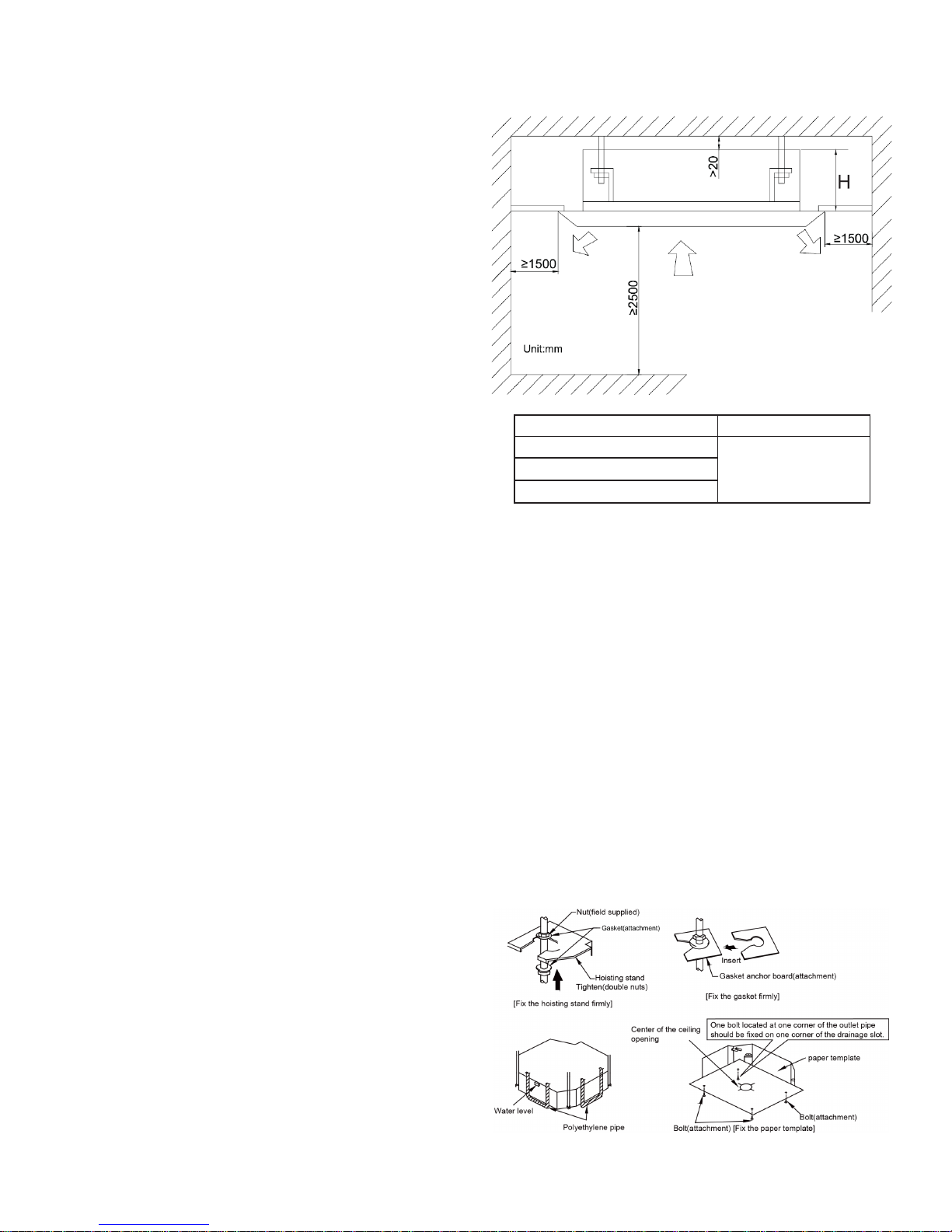
8.2.2. Installation Site
Select an installation site where the following conditions
are fullled and that meets your customer's
approval.
(1) Obstruct should be put away from the intake or outlet
vent of the indoor unit so that the airow
can be blown through all the room.
(2) Make sure that the installation meets the requirement
of the schematic diagram of installation
spaces.
(3) Select the place where can stand 4 times of the
weight of the indoor unit and would not increase
the operating noise and vibration.
(4) The horizontality of the installation place should be
guaranteed.
(5) Select the place where is easy to drain out the
condensate water, and connect with outdoor unit.
(6) Make sure that there are enough space for care and
maintenance, and the height fall between
the indoor unit and ground is above 1800mm.
(7) When installing the suspension bolt, check if the
installation place can stand 4 times of the
weight of the unit. If not, reinforce it before installation.
Note: There will be large amount of greasy dirt
accumulated on the fan, heat exchanger and water
pump located in the dinning room and kitchen, which
would reduce the capacity of the heater exchanger,
lead to leakage and abnormal operation of the water
pump.
8.2.3. Installing the Main Body Unit
(1) Install the hoisting stand on the hoisting screw by using
nuts and gaskets at both the upper and lower sides of the
hoisting stand. To prevent the gasket from breaking off, a
gasket anchor board can be helpful.
(2) Install the paper template on the unit, and x the drain
pipe at the outlet vent.
(3) Adjust the unit to the best position.
(4) Check if the unit is installed horizontally at four
directions. If not, the water pump and the oat switch
would function improperly and even lead to water leakage.
(5) Remove the gasket anchor board and tighten the nut
remained.
(6). Remove the paper template.
53
Note: There will be large amount of greasy dirt accumulated o n the fan, heat exchanger and water
pump located in the dinning room and kitchen, which would reduce the capacity of the heater exchanger,
lead to leakage and abnormal operation of the water pump.
Figure 3-1-24
Models H(mm)
MV-C12BI
240
MV-C18BI
MV-C24BI
Fig.1
Fig.2
Page 26
22
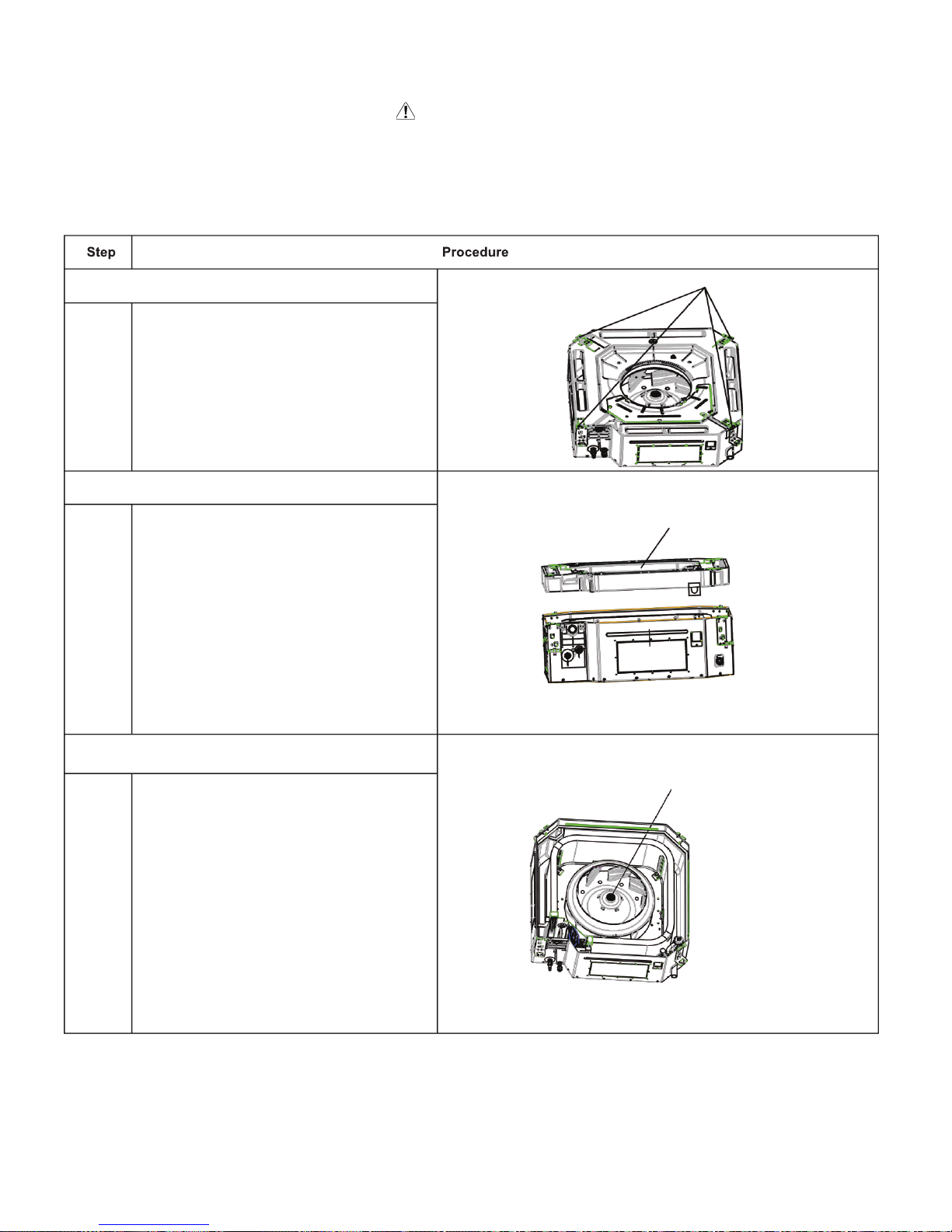
Service Manual
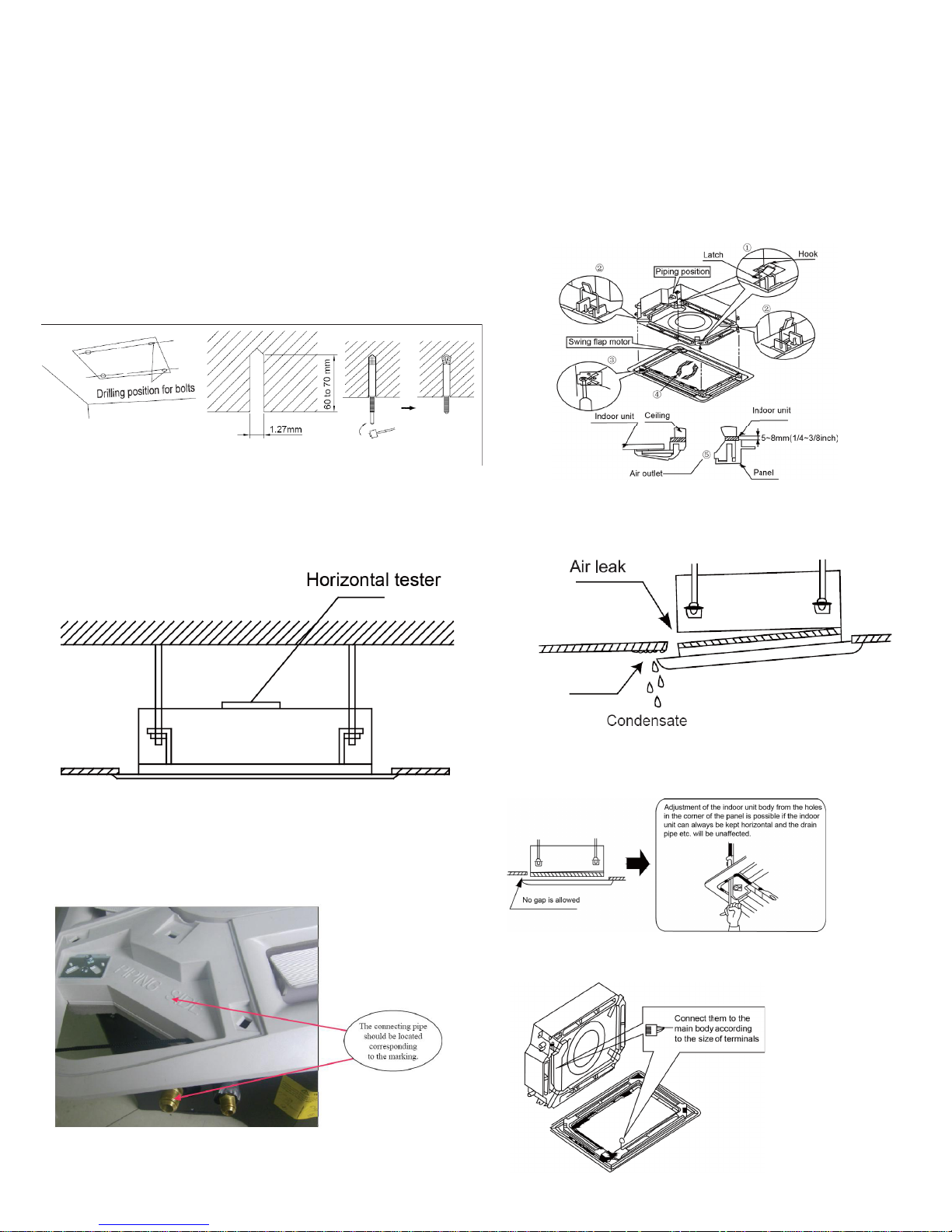
8.2.3. Installing the Suspension Bolts
(1) Using the installation template, drill holes for bolts (four
holes).
(2) Install the bolts to the ceiling at a place strong enough to
hang the unit. Mark the bolt positions from the installation
template. With a concrete drill, drill for 12.7 mm (1/2”) diameter
holes.
(3) Insert the anchor bolts into the drilled holes, and drive the
pins completely into the anchor bolts with a hammer.
8.2.4. Leveling
The water level test must be done after installing the indoor unit
to make the unit is horizontal, as shown below.
8.2.5. The Panel Installation
(1) See the gure below for the relationship of the front panel
and the connecting pipe.
(2) Place the panel at the unit, and latch the hooks beside and
opposite the swing ap motor.
(3) Latch other two hooks.
(4) Tighten four hexagonal screws under the latches about
15mm.
(5) Adjust the panel along the direction indicated by the arrow
as shown in Fig.8.
(6) Tighten the screws until the thickness of the sealing material
between the panel and the indoor unit reduces to 5-8cm.
(7) Improper screwing of the screws may cause the troubles
shown in Fig9.
(8) If gap still exists between ceiling and decoration panel
after tightening the screws, readjust the height of the indoor
unit. Fig10.
Fig.3
Fig.4
Fig.5
Fig.3 Fig.4 Fig.5
Fig.6
Fig.7
Fig.9
Fig.8
Fig.10
(9) Wire the swing ap motor as shown in Fig11.
Fig.11
Page 27

23
Service Manual
9. Maintenance
9.1 Error Code List
F0
(
7KH'XDO&RGH
'LVSOD\ZLOOVKRZ
)DQGWKHFRPSOHWH
XQLWVWRSV
,QGHIHFWRI
UHIULJHUDQW
,QGHIHFWRI
UHIULJHUDQW
,QGRRUHYDSRUDWRU
WHPSHUDWXUHVHQVRU
ZRUNVDEQRUPDOO\
7KHXQLWKDVEHHQ
SOXJJHGXSVRPHZKHUH
Full water
protection
Water level
switch
If cut-off of water level switch is
detected for 8s s
uccessively once
energized, the system will enter
full water protection. In this case,
switch off the unit and then switch
it on to eliminate this malfunction.
Page 28

24
Service Manual
9.2 Troubleshooting for Main Malfunction
●Indoor unit:
1. Malfunction of Temperature Sensor F1, F2
Main detection points:
● Is the wiring terminal between the temperature sensor and the controller loosened or poorly contacted?
● Is there short circuit due to trip-over of the parts?
● Is the temperature sensor broken?
● Is mainboard broken?
Malfunction diagnosis process:
Is the wiring terminal between the
temperature sensor and the controller
loosened or poorly contacted?
Start
Insert the temperature
sensor tightly
Yes
Yes
Yes
Yes
Yes
Yes
No
No
No
No
No
No
Is malfunction
eliminated
Is malfunction
eliminated
Is malfunction
eliminated
Replace it with a
temperature sensor with
the same model
Make the parts upright
Is there short circuit due to trip-
over of the parts
Is the temperature sensor normal
according to the resistance table?
Replace the mainboard with
the same model.
End
Page 29
25
Service Manual
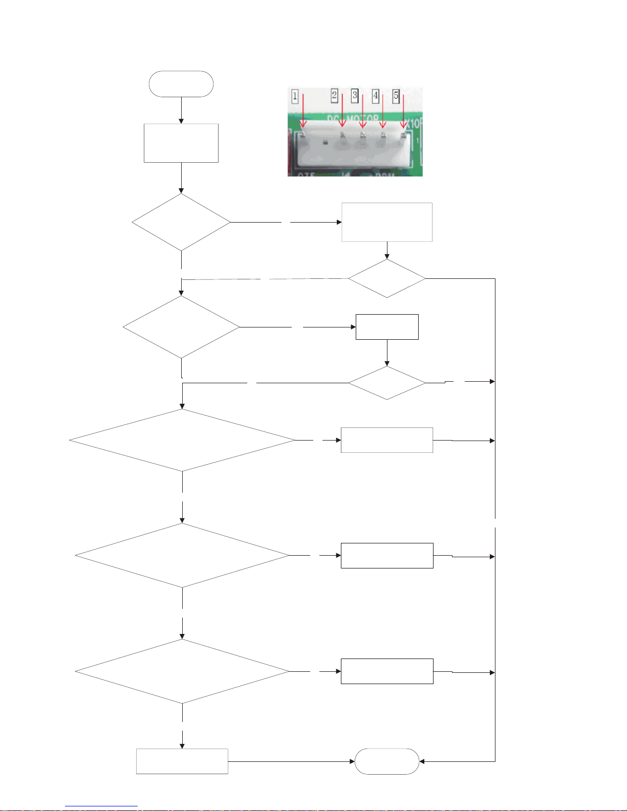
2. Malfunction of Blocked Protection of IDU Fan Motor H6
END
No
Yes
No
Ye
s
No
Yes
Yes
Yes
No
No
No
Yes
Yes
No
Turn the fan blades
by hand under
power-off condition
Whether the fan blades
can run smoothly?
Adjust the motor and blade
assembly so that rotor can run
smoothly.
Under power-off condition,
check whether the wiring terminal
between
indoor fan and main
board is loose.
Turn unit on
to check whether the
malfunction is
eliminated.
Turn unit on
to check whether the
malfunction is
eliminated.
Reinsert the wiring
terminal of indoor fan.
It's the malfunction of main board.
Replace a new main board that is
of the same model.
It's the malfunction of main board.
Replace a new main board that is
of the same model.
Replace a new main board that is
of the same model.
It's the malfunction of main board.
Then check whether the voltage
between terminal 2 and terminal 3
of the motor interface is 15VDC.
Connect power and restart the unit.
Test whether the voltage between terminal 1 and terminal 2
of motor interface is within 280~310VDC.
Then check whether there is voltage
between terminal 2 and terminal 4
of the motor interface.
It's the malfunction of motor.
Replace a new motor that is
of the same model.
Start
Page 30
26
Service Manual
3. Malfunction of Protection of Jumper Cap C5
Main detection points:
● Is there jumper cap on the mainboard?
● Is the jumper cap inserted correctly and tightly?
● The jumper is broken?
● The motor is broken?
● Detection circuit of the mainboard is dened abnormal?
Malfunction diagnosis process:
Start
Is there jumper cap on the mainboard?
Is the jumper cap inserted correctly
and tightly?
Replace the jumper cap with
the same model
Appearance of the
jumper cap
Assemble the jumper
cap with the same model
Insert the jumper
cap tightly
Is malfunction
eliminated
Is malfunction
eliminated
Is malfunction
eliminated
Replace the mainboard
with the same model
End
Yes
Yes
Yes
Yes
Yes
No
No
No
No
No
Page 31

27
Service Manual
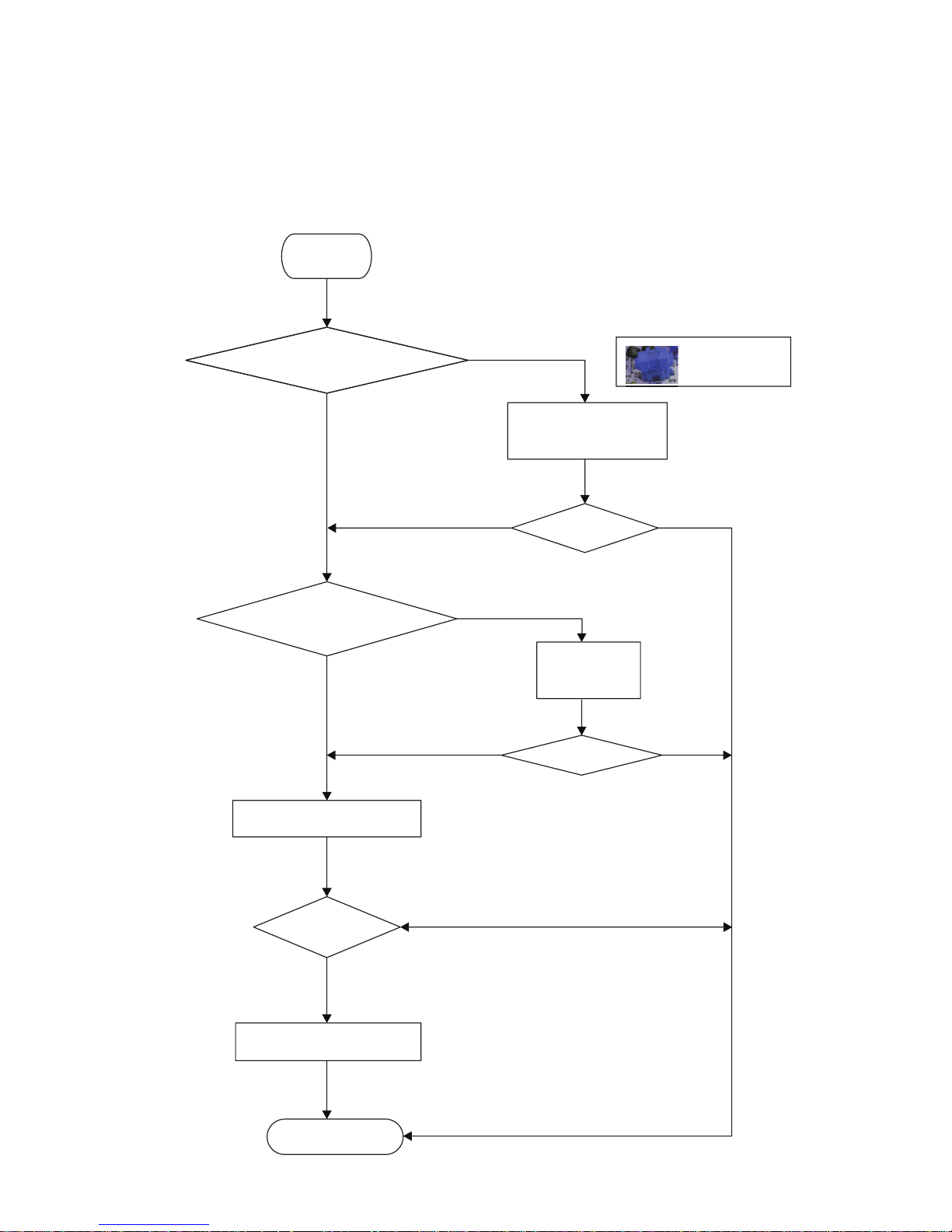
4. Communication malfunction E6
Start
Cut off power supply. Check if
connection line of IDU and ODU
and the wire inside electric box
are correctly connected.
Correct connection?
Main board matches
with display board? Main board of
IDU matches with that of ODU?
Communication cord is damaged?
Replace IDU's
main board
Malfunction eliminated?
End
Connect the line
according to
wiring diagram.
Match correctly
according to product
specification
Replace
communication
cord
Replace ODU's
main board.
Malfunction eliminated?
Malfunction eliminated?
Malfunction eliminated?
yes
yes
yes
yes
yes
yes
yes
no
no
no
no
no
no
no
Page 32

28
Service Manual
5.
The refrigerant is leaking
Check the leaking status of refrigerant
and charge refrigerant
Clean the heat exchangers
and remove
blockage of air inlet/outlet.
Heat exchangers are
too dirty or the air inlet/outlet
is blocked.
End
Remove blockage in the system
System is blocked inside
(dirt block, ice block, oil block, Y-valve no
fully open).
Compressor doesn't work
normally. Strange noise or leakage occurs.
Make compressor run normally.
Casing is too hot.
Replace a main
board with the
same model.
Malfunction is
eliminated.
Malfunction is
eliminated.
Malfunction is
eliminated.
Malfunction is
eliminated.
Troubleshooting
for F0 malfunction
Yes
No
No
No
No
No
No
No
No
Yes
Yes
Yes
Yes
Yes
Yes
Yes
Page 33

29
Service Manual
6. Full Water Protection E9
Page 34

30
Service Manual
Possible Causes Discriminating Method (Air conditioner Status) Troubleshooting
Set temperature is improper Observe the set temperature on remote controller Adjust the set temperature
Rotation speed of the IDU fan
motor is set too low
Small wind blow Set the fan speed at high or medium
Filter of indoor unit is blocked Check the lter to see it's blocked Clean the lter
Installation position for indoor unit
and outdoor unit is improper
Check whether the installation postion is proper
according to installation requirement for air
conditioner
Adjust the installation position, and install the
rainproof and sunproof for outdoor unit
Refrigerant is leaking
Discharged air temperature during cooling is
higher than normal discharged wind temperature;
Discharged air temperature during heating is
lower than normal discharged wind temperature;
Unit's pressure is much lower than regulated
range
Find out the leakage causes and deal with it.
Add refrigerant.
Malfunction of 4-way valve Blow cold wind during heating Replace the 4-way valve
Malfunction of capillary
Discharged air temperature during cooling is
higher than normal discharged wind temperature;
Discharged air temperature during heating is
lower than normal discharged wind temperature;
Unit't pressure is much lower than regulated
range. If refrigerant isn’t leaking, part of capillary
is blocked
Replace the capillary
Flow volume of valve is
insufcient
The pressure of valves is much lower than that
stated in the specication
Open the valve completely
Malfunction of horizontal louver Horizontal louver can’t swing
Refer to point 3 of maintenance method for
details
Malfunction of the IDU fan motor The IDU fan motor can’t operate
Refer to troubleshooting for H6 for maintenance
method in details
Malfunction of the ODU fan motor The ODU fan motor can't operate
Refer to point 4 of maintenance method for
details
Malfunction of compressor Compressor can't operate
Refer to point 5 of maintenance method for
details
9.3 Maintenance Method for Normal Malfunction
1. Air Conditioner Can't be Started Up
2. Poor Cooling (Heating) for Air Conditioner
3. Horizontal Louver Can't Swing
Possible Causes Discriminating Method (Air conditioner Status) Troubleshooting
No power supply, or poor
connection for power plug
After energization, operation indicator isn’t bright
and the buzzer can't give out sound
Conrm whether it's due to power failure. If yes,
wait for power recovery. If not, check power
supply circuit and make sure the power plug is
connected well.
Wrong wire connection between
indoor unit and outdoor unit,
or poor connection for wiring
terminals
Under normal power supply circumstances,
operation indicator isn't bright after energization
Check the circuit according to circuit diagram
and connect wires correctly. Make sure all
wiring terminals are connected rmly
Electric leakage for air conditioner
After energization, room circuit breaker trips off at
once
Make sure the air conditioner is grounded
reliably
Make sure wires of air conditioner is connected
correctly
Check the wiring inside air conditioner. Check
whether the insulation layer of power cord is
damaged; if yes, place the power cord.
Model selection for air switch is
improper
After energization, air switch trips off Select proper air switch
Malfunction of remote controller
After energization, operation indicator is bright,
while no display on remote controller or buttons
have no action.
Replace batteries for remote controller
Repair or replace remote controller
Possible Causes Discriminating Method (Air conditioner Status) Troubleshooting
Wrong wire connection, or poor
connection
Check the wiring status according to circuit
diagram
Connect wires according to wiring diagram to
make sure all wiring terminals are connected
rmly
Stepping motor is damaged Stepping motor can't operate Repair or replace stepping motor
Main board is damaged
Others are all normal, while horizontal louver
can't operate
Replace the main board with the same model
Page 35

31
Service Manual
7. Abnormal Sound and Vibration
Possible causes Discriminating method (air conditioner status) Troubleshooting
When turn on or turn off the unit,
the panel and other parts will
expand and there's abnormal
sound
There's the sound of "PAPA"
Normal phenomenon. Abnormal sound will
disappear after a few minutes.
When turn on or turn off the unit,
there's abnormal sound due
to ow of refrigerant inside air
conditioner
Water-running sound can be heard
Normal phenomenon. Abnormal sound will
disappear after a few minutes.
Foreign objects inside the indoor
unit or there're parts touching
together inside the indoor unit
There's abnormal sound fro indoor unit
Remove foreign objects. Adjust all parts'
position of indoor unit, tighten screws and stick
damping plaster between connected parts
Foreign objects inside the outdoor
unit or there're parts touching
together inside the outdoor unit
There's abnormal sound fro outdoor unit
Remove foreign objects. Adjust all parts'
position of outdoor unit, tighten screws and
stick damping plaster between connected parts
Short circuit inside the magnetic
coil
During heating, the way valve has abnormal
electromagnetic sound
Replace magnetic coil
Abnormal shake of compressor Outdoor unit gives out abnormal sound
Adjust the support foot mat of compressor,
tighten the bolts
Abnormal sound inside the
compressor
Abnormal sound inside the compressor
If add too much refrigerant during maintenance,
please reduce refrigerant properly. Replace
compressor for other circumstances.
6. Air Conditioner is Leaking
Possible causes Discriminating method (air conditioner status) Troubleshooting
Drain pipe is blocked Water leaking from indoor unit
Eliminate the foreign objects inside the drain
pipe
Drain pipe is broken Water leaking from drain pipe Replace drain pipe
Wrapping is not tight
Water leaking from the pipe connection place of
indoor unit
Wrap it again and bundle it tightly
5. Compressor Can't Operate
Possible causes Discriminating method (air conditioner status) Troubleshooting
Wrong wire connection, or poor
connection
Check the wiring status according to circuit
diagram
Connect wires according to wiring diagram to
make sure all wiring terminals are connected
rmly
Capacity of compressor is
damaged
Measure the capacity of fan capacitor with an
universal meter and nd that the capacity is out of
the deviation range indicated on the nameplate of
fan capacitor.
Replace the compressor capacitor
Power voltage is a little low or
high
Use universal meter to measure the power supply
voltage. The voltage is a little high or low
Suggest to equip with voltage regulator
Coil of compressor is burnt out
Use universal meter to measure the resistance
between compressor terminals and it's 0
Repair or replace compressor
Cylinder of compressor is blocked Compressor can't operate Repair or replace compressor
4. ODU Fan Motor Can't Operate
Possible causes Discriminating method (air conditioner status) Troubleshooting
Wrong wire connection, or poor
connection
Check the wiring status according to circuit
diagram
Connect wires according to wiring diagram to
make sure all wiring terminals are connected
rmly
Capacity of the ODU fan motor is
damaged
Measure the capacity of fan capacitor with an
universal meter and nd that the capacity is out of
the deviation range indicated on the nameplate of
fan capacitor.
Replace the capacity of fan
Power voltage is a little low or
high
Use universal meter to measure the power supply
voltage. The voltage is a little high or low
Suggest to equip with voltage regulator
Motor of outdoor unit is damaged
When unit is on, cooling/heating performance
is bad and ODU compressor generates a lot of
noise and heat.
Change compressor oil and refrigerant. If no
better, replace the compressor with a new one
Page 36
38
Service Manual
11. Removal Procedure
Warning: Be sure to wait for a minimum of 20 minutes
after turning off all power supplies and discharge the
refrigerant completely before removal.
1. Loosen the screws
fixing the water tray
Use screwdriver to loosen
the screws fixing the water
tray
2. Remove the water
tray
Remove the water tray
3. Loosen the bolts fixing the fan
Use spanner to loosen the
bolts fixing the fan.
Page 37
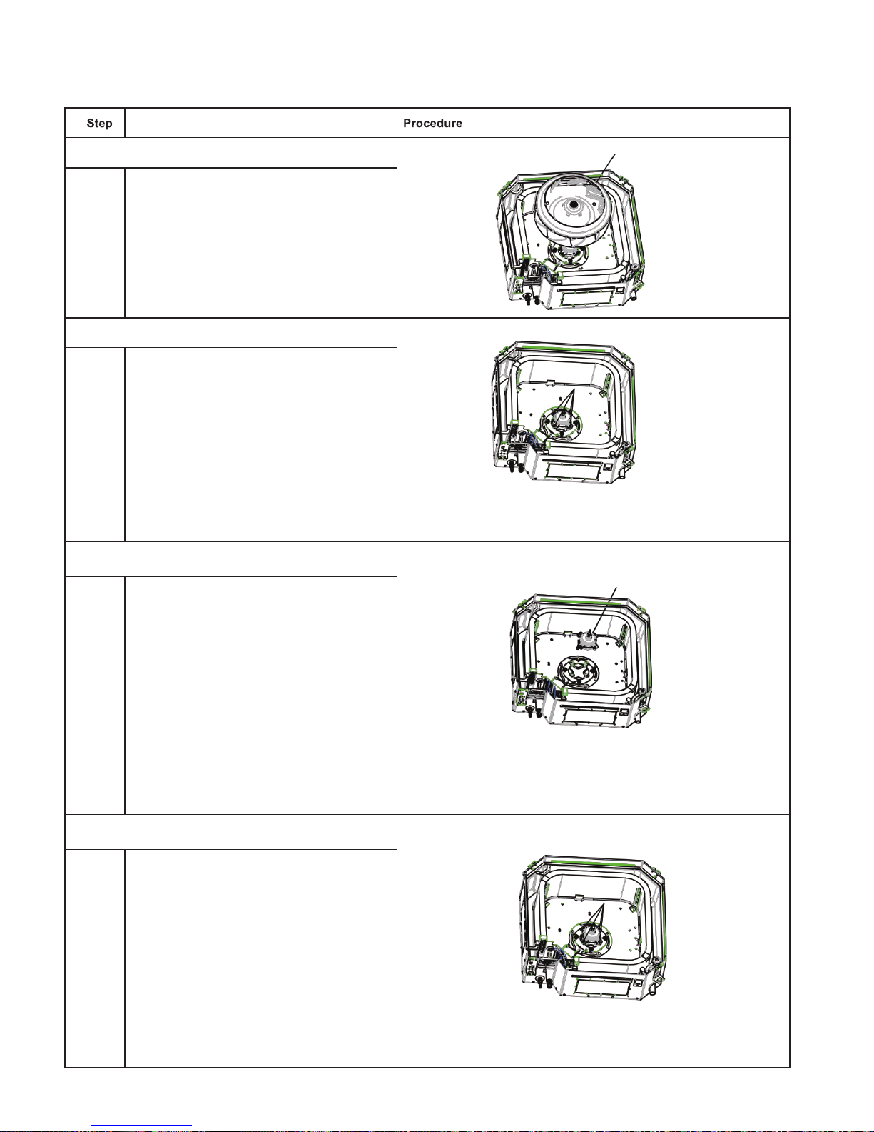
39
Service Manual
4. Remove the fan
Remove the fan
5. Loosen the screws
fixing the motor
Use screwdriver to loosen
the screws fixing the motor
6. Remove the motor and replace it
Remove the motor and
replace it
7. Tighten the screws
fixing the motor
Use screwdriver to tighten
the screws fixing the motor.
Page 38

40
Service Manual
8. Mount the fan and
tighten the fixing bolts
Mount the fan and use
spanner to tighten the bolts
fixing the fan.
9. Mount the water
tray and tighten the
screws
Use screwdriver to loosen
the screws fixing the water
tray
10.Removal and Installation of Drainage Pump
Loosen the screws
a
b
c
fixing the water tray
Use screwdriver to loosen the screws
fixing the water tray
Remove the water tray
Remove the water pump
and replace it.
Pull out the water outlet pipe and loosen
the screws fixing the water pump.
Pull out the water outlet pipe and use
screwdriver to loosen the screws fixing
the water pump.
Page 39

41
Service Manual
Ta ke out the pump and replace it
Connect the drainage pipe
and use
screwdriver to tighten the screws fixing
the water pump.
Mount the water tray and tighten the screws
Use screwdriver to loosen the screws
fixing the water tray
e
f
g
Page 40

42
Service Manual
Appendix:
Appendix 1: Reference Sheet of Celsius and Fahrenheit
Set temperature
Conversion formula for Fahrenheit degree and Celsius degree: Tf=Tcx1.8+32
Ambient temperature
Fahrenheit
display
temperature
(oF)
Fahrenheit
(oF)
Celsius(oC)
Fahrenheit
display
temperature
(oF)
Fahrenheit
(oF)
Celsius(oC)
Fahrenheit
display
temperature
(oF)
Fahrenheit
(oF)
Celsius(oC)
32/33 32 0 55/56 55.4 13 79/80 78.8 26
34/35 33.8 1 57/58 57.2 14 81 80.6 27
36 35.6 2 59/60 59 15 82/83 82.4 28
37/38 37.4 3 61/62 60.8 16 84/85 84.2 29
39/40 39.2 4 63 62.6 17 86/87 86 30
41/42 41 5 64/65 64.4 18 88/89 87.8 31
43/44 42.8 6 66/67 66.2 19 90 89.6 32
45 44.6 7 68/69 68 20 91/92 91.4 33
46/47 46.4 8 70/71 69.8 21 93/94 93.2 34
48/49 48.2 9 72 71.6 22 95/96 95 35
50/51 50 10 73/74 73.4 23 97/98 96.8 36
52/53 51.8 11 75/76 75.2 24 99 98.6 37
54 53.6 12 77/78 77 25
Fahrenheit
display
temperature
(oF)
Fahrenheit
(oF)
Celsius(oC)
Fahrenheit
display
temperature
(oF)
Fahrenheit
(oF)
Celsius(oC)
Fahrenheit
display
temperature
(oF)
Fahrenheit
(oF)
Celsius(oC)
61 60.8 16 69/70 69.8 21 78/79 78.8 26
62/63 62.6 17 71/72 71.6 22 80/81 80.6 27
64/65 64.4 18 73/74 73.4 23 82/83 82.4 28
66/67 66.2 19 75/76 75.2 24 84/85 84.2 29
68 68 20 77 77 25 86 86 30
1.Standard length of connection pipe
● 5m, 7.5m, 8m.
2.Min length of connection pipeFor the unit with standard connection pipe of 5m, there is no limitation for themin length of
connection pipe. For the unit with standard connection pipe of 7.5m and 8m, the min length of connection pipe is 3m.
3.Max length of connection pipe(More details please refer to the specications
)
4.The additional refrigerant oil and refrigerant charging required after prolonging connection pipe
● After the length of connection pipe is prolonged for 10m at the basis of standard length, you should add 5ml of refrigerant oil for
each additional 5m of connection pipe.
● The calculation method of additional refrigerant charging amount (on the basis of liquid pipe):
● Basing on the length of standard pipe, add refrigerant according to the requirement as shown in the table. The additional
refrigerant charging amount per meter is different according to the diameter of liquid pipe. See Sheet 2.
● Additional refrigerant charging amount = prolonged length of liquid pipe X additional refrigerant charging amount per meter
Appendix 2: Conguration of Connection Pipe
Additional refrigerant charging amount for R32
Diameter of connection pipe Indoor unit throttl Outdoor unit throttle
Liquid pipe Gas pipe
Cooling only,cooling
and heating(g / m)
Cooling only(g / m) Cooling and heating(g / m)
Ф6 Ф9.5 or Ф12 16 12 16
Ф6 or Ф9.5 Ф16 or Ф19 40 12 40
Ф12 Ф19 or Ф22.2 80 24 96
Ф16 Ф25.4 or Ф31.8 136 48 96
Ф19 / 200 200 200
Ф22.2 / 280 280 280
Note: The additional refrigerant charging amount in Sheet 2 is recommendedvalue, not compulsory.
Page 41

43
Service Manual
F:Inspection
● Check the quality of expanding port. If there is any blemish, expand the
port again according to the steps above.
The length is equal
Improper expanding
leaning
damaged
surface
crack uneven
thicknes
s
Smooth surface
Pipe
Shaper
Union pipe
Expander
Hard
mold
Pipe
Pipe
Pipe cutter
Leaning Uneven Burr
Improper pipe expanding is the main cause of refrigerant leakage.Please
expand the pipe according to the following steps:
A:Cut the pip
● Conrm the pipe length according to the distance of indoor unit and outdoor unit.
● Cut the required pipe with pipe cutter.
B:Remove the burrs
● Remove the burrs with shaper and prevent the burrs from getting into the pipe.
C:Put on suitable insulating pipe
D:Put on the union nut
● Remove the union nut on the indoor connection pipe and outdoor valve; install
the union nut on the pipe.
E:Expand the port
● Expand the port with expander.
● "A" is different according to the diameter, please refer to the sheet below:
Outer diameter(mm)
A(mm)
Max Min
Ф6 - 6.35 (1/4") 1.3 0.7
Ф9.52 (3/8”) 1.6 1.0
Ф12 - 12.7 (1/2”) 1.8 1.0
Ф15.8 - 16 (5/8”) 2.4 2.2
Appendix 3: Pipe Expanding Method
Note:
Note:
Page 42

Appendix 4: List of Resistance for Temperature Sensor
Resistance Table of Ambient Temperature Sensor for Indoor and Outdoor (15K)
Temp(oC) Resistance(kΩ) Temp(oC) Resistance(kΩ) Temp(oC) Resistance(kΩ) Temp(oC) Resistance(kΩ)
-19 138.1 20 18.75 59 3.848 98 1.071
-18 128.6 21 17.93 60 3.711 99 1.039
-17 121.6 22 17.14 61 3.579 100 1.009
-16 115 23 16.39 62 3.454 101 0.98
-15 108.7 24 15.68 63 3.333 102 0.952
-14 102.9 25 15 64 3.217 103 0.925
-13 97.4 26 14.36 65 3.105 104 0.898
-12 92.22 27 13.74 66 2.998 105 0.873
-11 87.35 28 13.16 67 2.896 106 0.848
-10 82.75 29 12.6 68 2.797 107 0.825
-9 78.43 30 12.07 69 2.702 108 0.802
-8 74.35 31 11.57 70 2.611 109 0.779
-7 70.5 32 11.09 71 2.523 11 0 0.758
-6 66.88 33 10.63 72 2.439 111 0.737
-5 63.46 34 10.2 73 2.358 112 0.717
-4 60.23 35 9.779 74 2.28 11 3 0.697
-3 57.18 36 9.382 75 2.206 114 0.678
-2 54.31 37 9.003 76 2.133 115 0.66
-1 51.59 38 8.642 77 2.064 116 0.642
0 49.02 39 8.297 78 1.997 117 0.625
1 46.6 40 7.967 79 1.933 118 0.608
2 44.31 41 7.653 80 1.871 119 0.592
3 42.14 42 7.352 81 1.811 120 0.577
4 40.09 43 7.065 82 1.754 121 0.561
5 38.15 44 6.791 83 1.699 122 0.547
6 36.32 45 6.529 84 1.645 123 0.532
7 34.58 46 6.278 85 1.594 124 0.519
8 32.94 47 6.038 86 1.544 125 0.505
9 31.38 48 5.809 87 1.497 126 0.492
10 29.9 49 5.589 88 1.451 127 0.48
11 28.51 50 5.379 89 1.408 128 0.467
12 27.18 51 5.197 90 1.363 129 0.456
13 25.92 52 4.986 91 1.322 130 0.444
14 24.73 53 4.802 92 1.282 131 0.433
15 23.6 54 4.625 93 1.244 132 0.422
16 22.53 55 4.456 94 1.207 133 0.412
17 21.51 56 4.294 95 1.171 134 0.401
18 20.54 57 4.139 96 1.136 135 0.391
19 19.63 58 3.99 97 1.103 136 0.382
Page 43

Resistance Table of Tube Temperature Sensors for Outdoor and Indoor (20K)
Temp(oC) Resistance(kΩ) Temp(oC) Resistance(kΩ) Temp(oC) Resistance(kΩ) Temp(oC) Resistance(kΩ)
-19 181.4 20 25.01 59 5.13 98 1.427
-18 171.4 21 23.9 60 4.948 99 1.386
-17 162.1 22 22.85 61 4.773 100 1.346
-16 153.3 23 21.85 62 4.605 101 1.307
-15 145 24 20.9 63 4.443 102 1.269
-14 137.2 25 20 64 4.289 103 1.233
-13 129.9 26 19.14 65 4.14 104 1.198
-12 123 27 18.13 66 3.998 105 1.164
-11 116.5 28 17.55 67 3.861 106 1.131
-10 110.3 29 16.8 68 3.729 107 1.099
-9 104.6 30 16.1 69 3.603 108 1.069
-8 99.13 31 15.43 70 3.481 109 1.039
-7 94 32 14.79 71 3.364 110 1.01
-6 89.17 33 14.18 72 3.252 111 0.983
-5 84.61 34 13.59 73 3.144 112 0.956
-4 80.31 35 13.04 74 3.04 113 0.93
-3 76.24 36 12.51 75 2.94 114 0.904
-2 72.41 37 12 76 2.844 115 0.88
-1 68.79 38 11.52 77 2.752 116 0.856
0 65.37 39 11.06 78 2.663 117 0.833
1 62.13 40 10.62 79 2.577 118 0.811
2 59.08 41 10.2 80 2.495 11 9 0.77
3 56.19 42 9.803 81 2.415 120 0.769
4 53.46 43 9.42 82 2.339 121 0.746
5 50.87 44 9.054 83 2.265 122 0.729
6 48.42 45 8.705 84 2.194 123 0.71
7 46.11 46 8.37 85 2.125 124 0.692
8 43.92 47 8.051 86 2.059 125 0.674
9 41.84 48 7.745 87 1.996 126 0.658
10 39.87 49 7.453 88 1.934 127 0.64
11 38.01 50 7.173 89 1.875 128 0.623
12 36.24 51 6.905 90 1.818 129 0.607
13 34.57 52 6.648 91 1.736 130 0.592
14 32.98 53 6.403 92 1.71 131 0.577
15 31.47 54 6.167 93 1.658 132 0.563
16 30.04 55 5.942 94 1.609 133 0.549
17 28.68 56 5.726 95 1.561 134 0.535
18 27.39 57 5.519 96 1.515 135 0.521
19 26.17 58 5.32 97 1.47 136 0.509
Page 44
Resistance Table of Discharge Temperature Sensor for Outdoor (50K)
Temp(oC) Resistance(kΩ) Temp(oC) Resistance(kΩ) Temp(oC) Resistance(kΩ) Temp(oC) Resistance(kΩ)
-29 853.5 10 98 49 18.34 88 4.75
-28 799.8 11 93.42 50 17.65 89 4.61
-27 750 12 89.07 51 16.99 90 4.47
-26 703.8 13 84.95 52 16.36 91 4.33
-25 660.8 14 81.05 53 15.75 92 4.20
-24 620.8 15 77.35 54 15.17 93 4.08
-23 580.6 16 73.83 55 14.62 94 3.96
-22 548.9 17 70.5 56 14.09 95 3.84
-21 516.6 18 67.34 57 13.58 96 3.73
-20 486.5 19 64.33 58 13.09 97 3.62
-19 458.3 20 61.48 59 12.62 98 3.51
-18 432 21 58.77 60 12.17 99 3.41
-17 407.4 22 56.19 61 11.74 100 3.32
-16 384.5 23 53.74 62 11.32 101 3.22
-15 362.9 24 51.41 63 10.93 102 3.13
-14 342.8 25 49.19 64 10.54 103 3.04
-13 323.9 26 47.08 65 10.18 104 2.96
-12 306.2 27 45.07 66 9.83 105 2.87
-11 289.6 28 43.16 67 9.49 106 2.79
-10 274 29 41.34 68 9.17 107 2.72
-9 259.3 30 39.61 69 8.85 108 2.64
-8 245.6 31 37.96 70 8.56 109 2.57
-7 232.6 32 36.38 71 8.27 11 0 2.50
-6 220.5 33 34.88 72 7.99 111 2.43
-5 209 34 33.45 73 7.73 112 2.37
-4 198.3 35 32.09 74 7.47 11 3 2.30
-3 199.1 36 30.79 75 7.22 11 4 2.24
-2 178.5 37 29.54 76 7.00 11 5 2.18
-1 169.5 38 28.36 77 6.76 11 6 2.12
0 161 39 27.23 78 6.54 11 7 2.07
1 153 40 26.15 79 6.33 11 8 2.02
2 145.4 41 25.11 80 6.13 11 9 1.96
3 138.3 42 24.13 81 5.93 120 1.91
4 131.5 43 23.19 82 5.75 121 1.86
5 125.1 44 22.29 83 5.57 122 1.82
6 119.1 45 21.43 84 5.39 123 1.77
7 113.4 46 20.6 85 5.22 124 1.73
8 108 47 19.81 86 5.06 125 1.68
9 102.8 48 19.06 87 4.90 126 1.64
GREE ELECTRIC APPLIANCES, INC. OF ZHUHAI
Add: West Jinji Rd, Qianshan, Zhuhai,Guangdong, China, 519070
Tel: (+86-756) 8522218
Fax: (+86-756) 8669426
E-mail: gree@gree.com.cn www.gree.com
HONG KONG GREE ELECTRIC APPLIANCES SALES LIMITED
Add: Unit 2612,26/F.,Miramar Tower 132 Nathan Road,TST,Kowloon,HK
Tel: (852) 31658898 Fax: (852) 31651029
For product improvement, specifications and appearance in this manual are subject to change without prior notice.
Page 45

PARTS GUIDE
MULTI VARIABLE SERIES
MV-C12BI, MV-C18BI, MV-C24BI
Page 46

MV-C12BI
Page 47

No Description Part Code Note Qty
Price Code
1 Rear Grill 26909400007 1 AE
2 Brushless DC Motor 15709400004 1 BB
3 Water Tray Assy 01289400004 1 AW
4 Water Pump 4313800005801 1 AY
5 Supporter none 0 6 Liquid Level Switch 450102013 1 AL
7 Pump Drainpipe 26909400069 1 AF
8 Water Pump Assy 15409400008 1 AZ
9 Right Side Plate Sub-Assy 01319400013 2 AK
10 Bottom Foam Assy 12509400004 1 AP
11 Base Plate Assy 02229400007 1 AS
12 Body Installing Support 01332705 4 AC
13 Left Side Plate Sub-Assy 01319400012 1 AK
14 Press Plate (Outlet Pipe) 01349400004 1 AD
15 Electric Box Assy 100002060081 1 AZ
16 Terminal Board 420001000002 1 AF
17 Wire Clamp 71010103 1 AB
18 Main Board 300002060012 1 AY
19 Electric Box Cover 01429400003 1 AK
20 Front Side Plate Sub-Assy 01319400014 1 AL
21 Drain Hose Sub-Assy 007008000001 1 AG
22 Room Sensor 39000191 1 AD
23 Tube sensor 3900012128 1 AD
24 Remote Controller 305100491_L41851 1 AT
25 Evaporator Assy 01029400058 1 BG
26 Supporter 01809400007 3 AD
27 Centrifugal Fan 10429400001 1 AW
28 Diversion Circle 10479400001 1 AG
1 Front Grill 26909400010 1 AL
2 Fastener Sub-assy 02209400001 2 AB
3 Receiver Board 30261016 1 AM
4 Guide Louver 26909400014 4 AF
5 Front Case 26909400009 1 AQ
6 Step Motor 15729401 4 AG
7 hook 02229400009 2 AD
8 Gland Bush 26909400012 4 AB
9 Corner Cover 26909400011 4 AD
10 Axile Bush none 0 11 Filter Sub-Assy 11729400001 1 AD
12 Front Grill Assy
01579400002_L41851
1 -
MODEL: MV-C12BI Cassette unit
The data are subject to change without notice.
MODEL: MV-C12BI Cassette unit: PANEL
Page 48
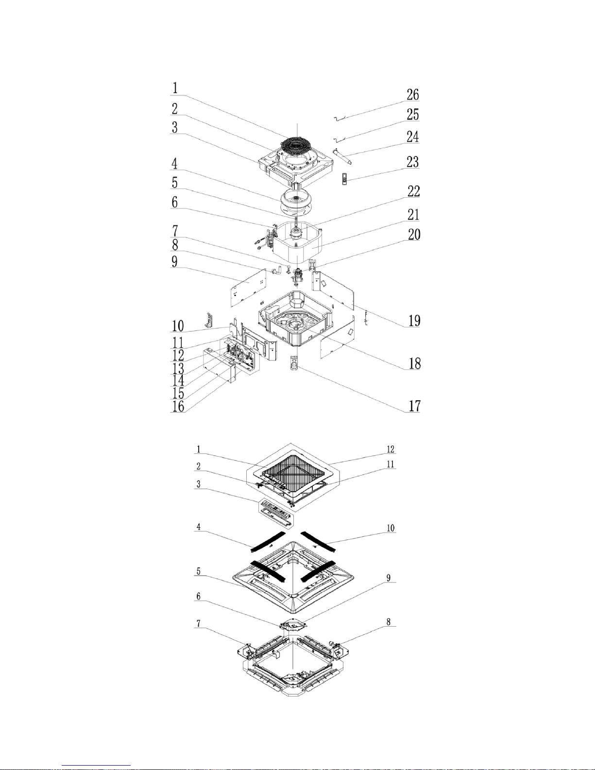
MV-C18BI
Page 49

No Description Part Code Note Qty
Price Code
1 Rear Grill 26909400007 1 AE
2 Diversion Circle 10479400001 1 AG
3 Water Tray Assy 01289400004 1 AW
4 Centrifugal Fan 10429400001 1 AW
5 Supporter 01809400007 3 AD
6 Baffle Plate Sub-assy 01359400002 1 AF
7 Liquid Level Switch 450102013 1 AL
8 Pump Drainpipe 26909400069 1 AF
9 Left Side Plate Sub-Assy 01319400012 1 AK
10 Press Plate (Outlet Pipe) 01349400004 1 AD
11 Front Side Plate Sub-Assy 01319400014 1 AL
12 Capacitor none 0 13 Terminal Board none 0 14 Terminal Board 420001000002 1 AF
15 Main Board 300002060012 1 AY
16 Electric Box Assy 100002060083 1 AZ
17 Body Installing Support 01332705 4 AC
18 Base Plate Assy 02229400007 1 AS
19 Right Side Plate Sub-Assy 01319400013 2 AK
20 Water Pump 4313800005801 1 AY
21 Evaporator Assy 01029400013 1 BG
22 Brushless DC Motor 15709400004 1 BB
23 Remote Controller 305100491_L41851 1 AT
24 Drain Hose Sub-Assy 007008000001 1 AG
25 Tube sensor 3900012128 1 AD
26 Room Sensor 39000191 1 AD
1 Front Grill 26909400010 1 AL
2 Fastener Sub-assy 02209400001 2 AB
3 Receiver Board 30261016 1 AM
4 Guide Louver 26909400014 4 AF
5 Front Case 26909400009 1 AQ
6 Step Motor 15729401 4 AG
7 Hook 02229400009 2 AD
8 Gland Bush 26909400012 4 AB
9 Corner Cover 26909400011 4 AD
10 Axile Bush none 0 11 Filter Sub-Assy 11729400001 1 AD
12 Front Grill Assy 01579400002_L41851 1 -
MODEL: MV-C18BI Cassette unit
The data are subject to change without notice.
MODEL: MV-C18BI Cassette unit: PANEL
Page 50

MV-C24BI
Page 51

No Description Part Code Note Qty
Price Code
1 Tube Exit Plate Assy 01382715 1 AE
2 Shell Assy 01432703 1 BC
3 Body Installing Plate 01332701 4 AC
4 Front Side Plate assy 01302718 1 AP
5 Left Side Plate Assy 01302715 1 AK
6 Base Plate Assy 01222701 1 AX
7 Rear Side Plate Assy 01302714 1 AP
8 Bottom Foam Assy 52012722 1 AR
9 Motor Gasket 76712711 4 AC
10 Motor support none 0 11 Fan Motor 1570940000401 1 12 Centrifugal Fan 10312705 1 AX
13 Connected Board Assy of Evaporator 01074042 1 AG
14 Filter Sub-Assy none 0 15 Drain Hose Sub-Assy 05339400001 1 AG
16 Water Tray Assy 000069000104 1 AY
17 Electric Base Plate 01412721 1 AK
18 Diversion Circle 10372701 1 AH
19 Electric Box Assy 100002060082 1 20 Transformer none 0 21 Terminal Board 420001000002 1 AF
22 Electric Box Cover 0142410004801A 1 AL
23 Electric Box Cover Sub-Assy1 none 0 24 Temperature Sensor 390001921G 1 AD
25 Room Sensor 390001911 1 AD
26 Electric Box Cover Sub-Assy2 none 0 27 Electric Box Cover II none 0 28 Main Board 300002060012 1 AY
29 Capacitor CBB61 none 0 30 Evaporator Assy 011001060292 1 31 Evaporator Support Assy 01072703 2 AD
32 Magnetic Ring 49010104 1 AC
33 Water Pump 43138000058 1 AX
34 Water Pump Assy 15409400009 1 BA
35 Pump Support none 0 36 Water Level Switch 45020216 1 AQ
37 Pump Drainpipe 26909400068 1 AG
38 Right Side Plate Assy 01302716 1 AK
39 Remote Controller 305100491_L41851 1 AT
40 Pump Cover Board Assy 01252713 1 AC
41 Display Board
30564103_L41851
1 BF
MODEL: MV-C24BI Cassette unit
The data are subject to change without notice.
Page 52

No Description Part Code Note Qty
Price Code
1 Front Grill 26909466 1 AP
2 Hanging Ring 70810101 4 AD
3 Outer Conner Cover Sub-assy 01269410 4 AE
4 Louver Motor Sub-assy 15409407 4 AG
5 Step Motor 15729401 1 AG
6 Crank 10582070 1 AB
7 Inner Conner Cover IV Sub-assy 01269411 1 AE
8 Inner Conner Cover III Sub-assy 01269412 1 AE
9 Foam 52069409 4 AF
10 Foam 52069410 4 AF
11 Inner Conner Cover II Sub-assy 01269413 1 AE
12 Display Board none 0 13 Inner Conner Cover I Sub-assy 01269414 1 AE
14 Axile Bush 10542036 4 AB
15 Guide Louver 10619406 4 AF
16 Left Axile Bush 10512037 4 AB
17 Magnet Sub-assy 70842705 1 AE
18 Front Panel Assy 01549401 1 AY
19 Filter Sub-Assy 11729405 1 AM
20 Clamp Sub-Assy 000101000001 1 AB
21 Front Grill Assy
01579400004_L41851
1 -
MODEL: MV-C24BI Cassette unit: PANEL
The data are subject to change without notice.
Page 53

Page 54

NOTE CONCERNING PROTECTION OF
ENVIRONMENT
This product must not be disposed of via normal household waste after its service life, but must be
taken to a collection station for the recycling of electrical and electronic devices. The symbol on the
product, the operating instructions or the packaging indicate such disposal procedures. The materials
are recyclable in accordance with their respective symbols. By means of re-use, material recycling or
any other form of recycling old appliances you are making an important contribution to the protection
of our environment. Please ask your local council where your nearest disposal station is located.
INFORMATION CONCERNING USED REFRIGERANT
MEDIUM
This unit is containing fluorinated gases included in the Kyoto protocol. The maintenance and the liquidation must
be carried out by qualified personnel.
Type of refrigerant: R32
The quantity of the refrigerant: please see the unit label.
The value GWP: 675 (1 kg R32 = 0,675 t CO2 eq)
GWP = Global Warming Potential
Appliance filled with flammable gas R32.
In case of quality problem or other please contact your local supplier or authorized service center.
Emergency number: 112
PRODUCER
SINCLAIR CORPORATION Ltd.
1-4 Argyll St.
London W1F 7LD
Great Britain
www.sinclair-world.com
This product was manufactured in China (Made in China).
REPRESENTATIVE
SINCLAIR EUROPE spol. s r.o.
Purkynova 45
612 00 Brno
Czech Republic
TECHNICAL SUPPORT
NEPA spol. s r.o.
Purkynova 45
612 00 Brno
Czech Republic
Tel.: +420 800 100 285
Fax: +420 541 590 124
www.sinclair-solutions.com
info@sinclair-solutions.com
 Loading...