

Page 1
AIR CONDITIONER
SPLIT AIR CONDITIONER WALL MOUNTED MODEL SINCLAIR
OWNER‘S MANUAL
ASH-09CS
ASH-12CS
SLIM SERIE
Before operating the unit please
carefully read this manual.
Page 2
1
The instructions before use
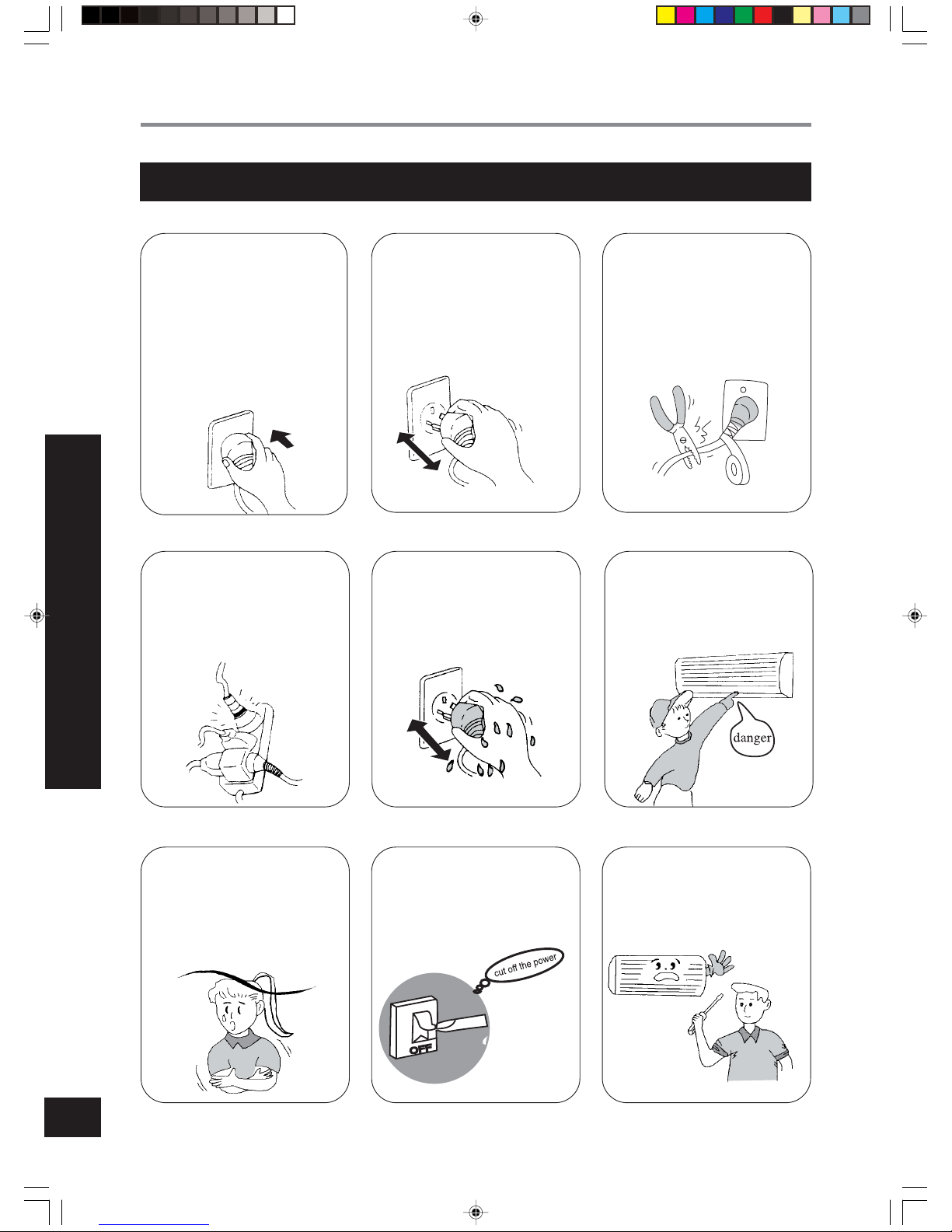
Never splice the power cord or
use an extended cord.
It can cause overheating or fire.
Don’t pull out the power plug
during operation.
It can cause an electric shock or
fire.
The power plug must be inserted tightly.
Otherwise, it can cause an electric shock, overheating or fire.
for the security of the air
conditioner,it should be safely
connected to earth .
The line that be connected to the
earth of the outdoor unit should
be connected correctly and
tightly.
WARNING
THE INSTRUCTIONS BEFORE USE
Don’t apply the cold wind to
the body for a longtime. It
cause the physical condition
deterioration and health
problems.
When having a burning smell
or smoke, please turn off the
power supply and contact with
the service center.
Don’t attempt to repair the air
conditioner by yourself.
You may cause further malfunctions
Don’t operate the Air conditioner with wet hands.
It can cause an electric shock .
Don’t use longer power lines
and don’t share a same socket
with other electric appliances.
It can cause an electric shock or
fire.
Don’t insert your hands or stick
into the air intake or outlet
vents.
It can cause danger.
66122452.p65 03-7-15, 17:251
Page 3
2
THE INSTRUCTIONS BEFORE USE
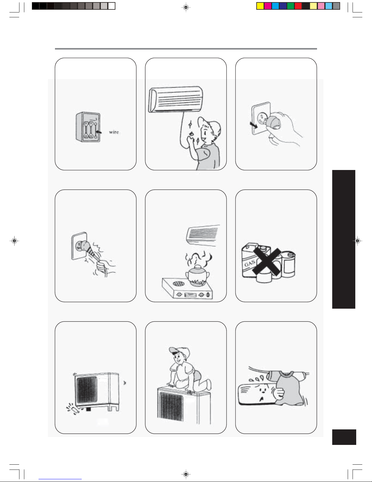
Please note whether the installed stand is firm enough or
not.
It leads to the falling of the unit
which causes the injury etc.
occasionally.
Don’t step on the top of the outdoor unit. As falling off the out-
door unit can be dangerous.
Don’t block the air intake or
outlet vents of both the outdoor
and indoor units. It can decrease
the air conditioning capacity or
cause a malfunction.
Don’t pull the power cord to
pull out the power plug.
It can cause fire.
Don’t place a space heater near
the air conditioner. Air flow
from the air conditioner can cause
incomplete combustion to the
space heater.
Keep combustible spray away
from the units.
It is likely to ignite and explode.
Don’t use any other fuse excluding the fuse of correct
capacity.
Improper wire could cause the
breaking down or fire.
Be sure to pull out the power
plug as the Air Conditioner will
not be used for a longtime.
When cleaning, it is necessary
to stop driving and turn off the
power suply.
It occasionally cause the electric
shock.
66122452.p65 03-7-15, 17:262
Page 4
3
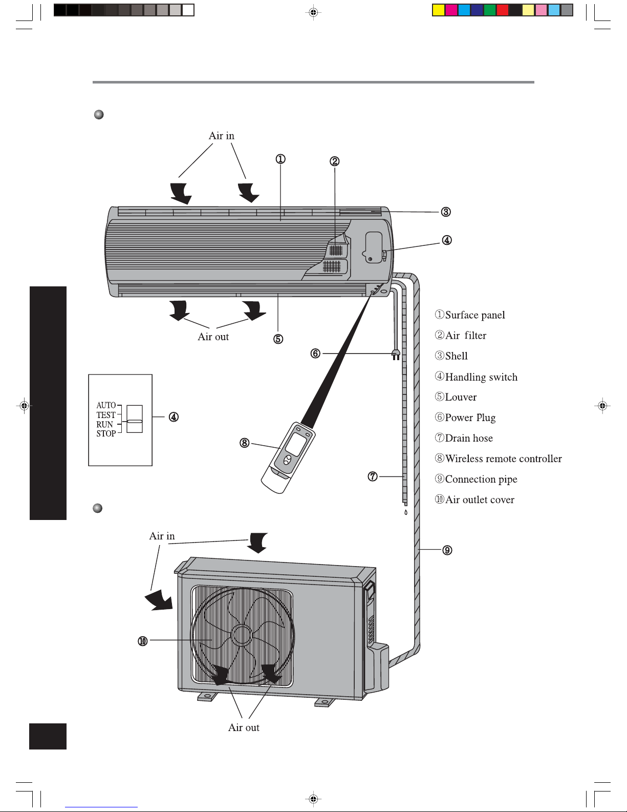
Name and function of each part
Indoor unit
NAME AND FUNCTION OF EACH PART
Outdoor unit
66122452.p65 03-7-15, 17:263
Page 5
4
Remote control operation procedure
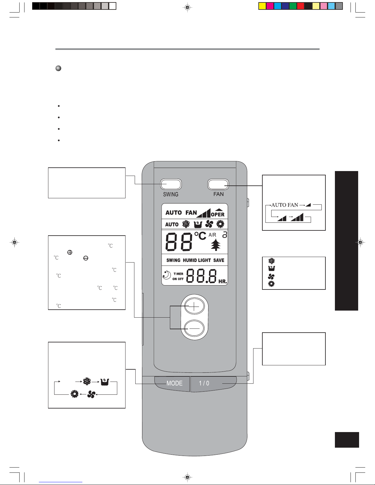
Name and Function-Remote control
Note:
Be sure that there are no obstructions between receiver and remote controller.
The remote control signal can be received at the distance of up to about 10m.
Don’t drop or throw the remote control.
Don’t let any liquid in the remote controller and put the remote controller di-
rectly under the sunlight or any place where is very hot.
SWING button
When it is pressed, the louvers
start to rotate automatically and
stop when repressed.
TEMP.button
SET TEMP. increases 1
by
pressing button once,and decreases
1
by pressing button once.
At COOL mode operation, SET
TEMP. can be selected from 16
to
30
.
At DRY mode operation, SET TEMP.
can be selected from 16
to 30 .
At HEAT mode operation, SET
TEMP. can be selected from 16
to
30
.
MODE button
press this button to change the
operation mode in order of:
FAN button
Press this button to change
the fan speed of:
“ ” COOL mode
“ ” DRY mode
“ ” FAN mode
“ ” HEAT mode
1/0 button
Press this button to turn on
or turn off the unit.
REMOTE CONTROL OPERATION PROCEDURE
AUTO
66122452.p65 03-7-15, 17:264
Page 6
5
REMOTE CONTROL OPERATION PROCEDURE
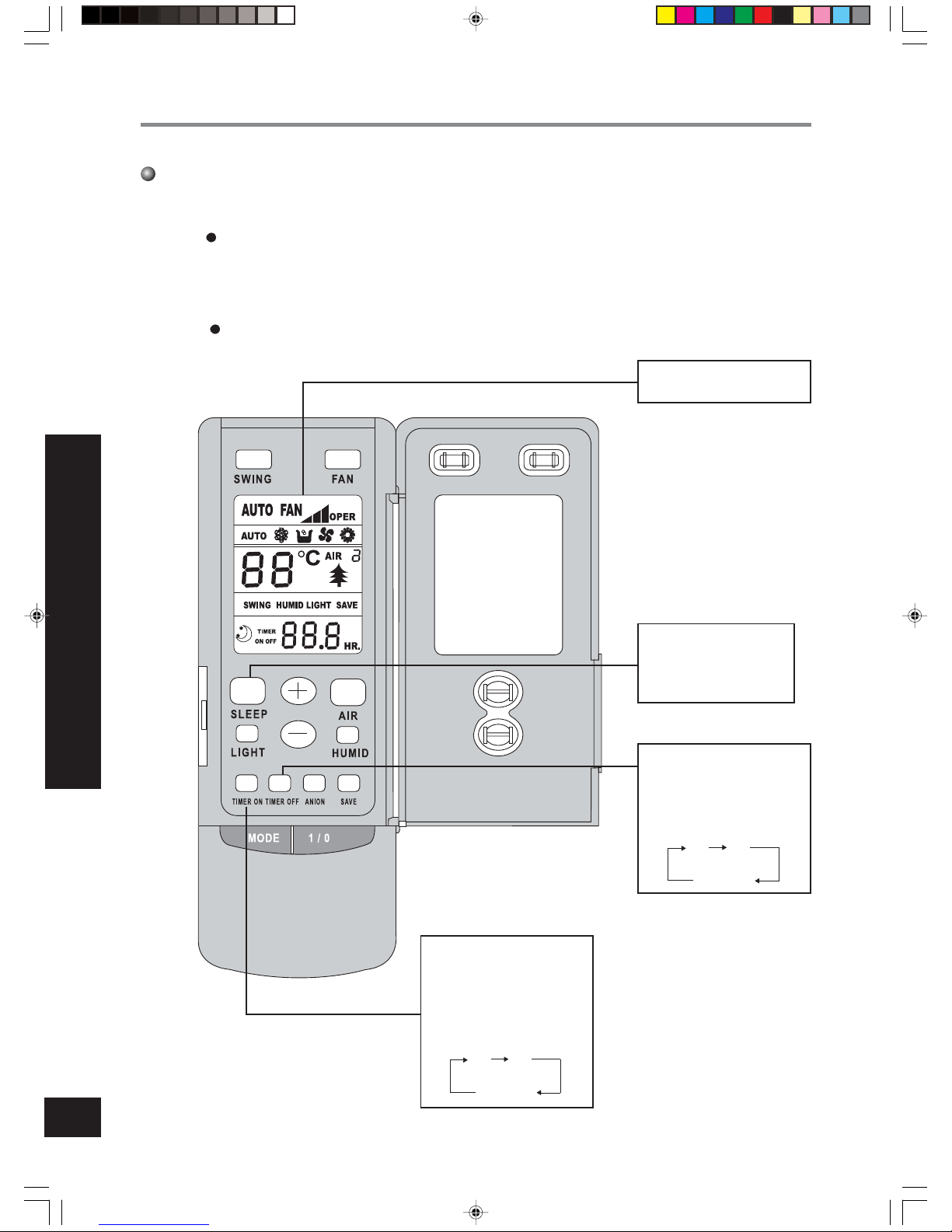
Name and Function-Remote control. (Remove the cover)
Note: This type of remote controller is a kind of new current controller.
some buttons of the controller which are not available to this Air condi-
tioner will not be described below.
Operate on unmentioned buttons would not impact on the normal use.
SLEEP button
Press this button to set
SLEEP operation. and stop
when repressed.
TIMER OFF button
At operating, press TIMER
OFF button, set OFF TIME
in range of 0 to 24 hour to
stop the unit automatically.
TIMER ON button
At stopping, press TIMER
ON button, set ON TIME in
range of 0 to 24 hour at the
interral of 0.5h to start the
unit automatically.
0 24h
Timer
cancellation
0 24h
Timer
cancellation
Liquid crystal displayer. It
shows all set contents.
66122452.p65 03-7-15, 17:265
Page 7
6
REMOTE CONTROL OPERATION PROCEDURE
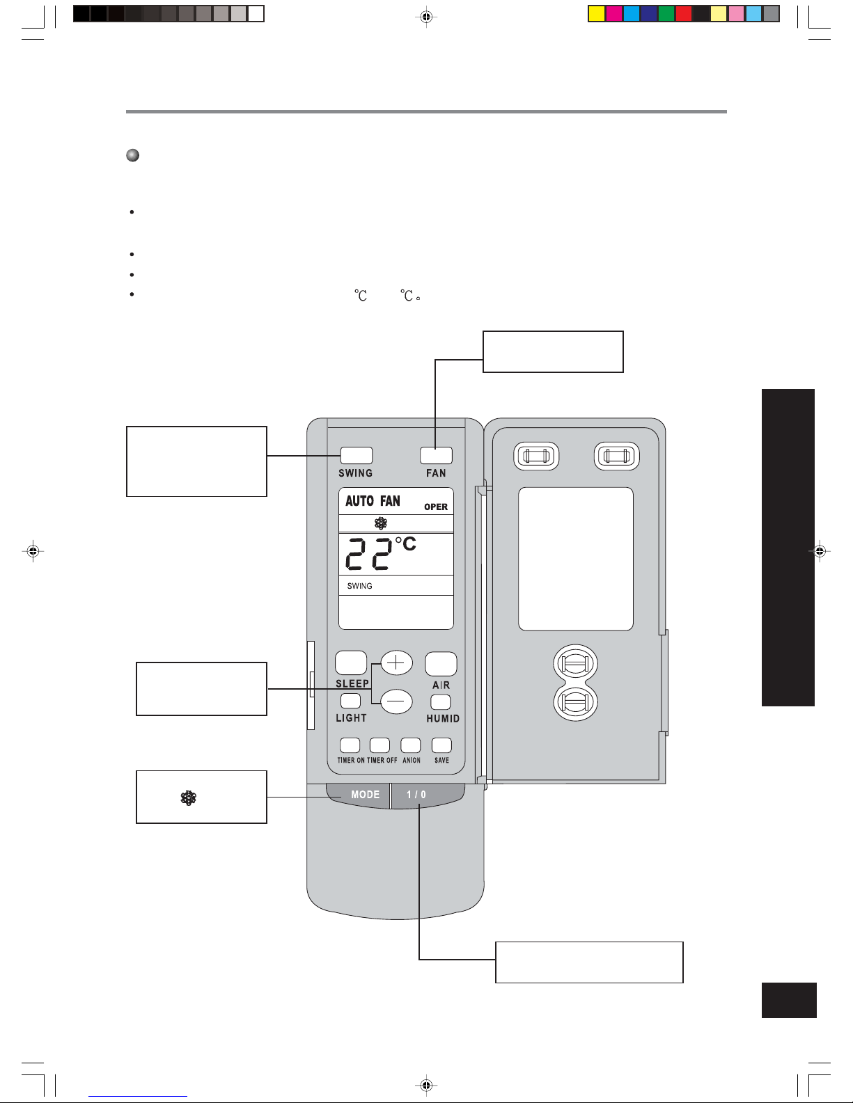
COOL mode operation procedure
According to difference between room temp. and set temp., microcomputer can control cooling on or
not.
If room temp. is higher than set temp., compressor runs at COOL mode.
If room temp. is lower than set temp., compressor stops and only indoor fan motor runs.
SET TEMP. should be in range of 16
to 30
4.Press FAN button, set
fan speed.
5.Press TEMP. but-
ton, set suitable SET
TEMP.
2.Press MODE button,
set operation
mode.
3.Press SWING button,
the louvers start to rotate automatically, and
stop when repress.
1.Plug in, press 1/0 button,then air
conditioner is turned on.
66122452.p65 03-7-15, 17:266
Page 8
7
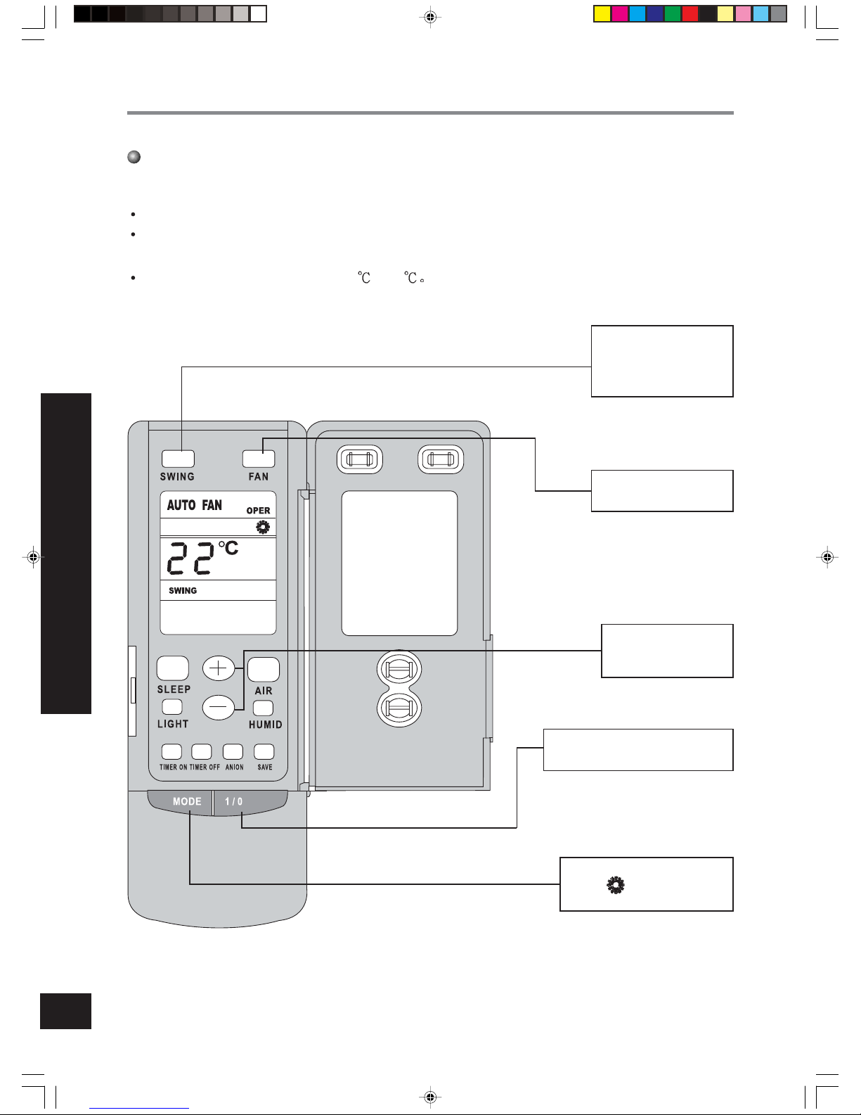
HEAT mode operation procedure
If room temp. is lower than set temp., compressor runs at HEAT mode;
If room temp. is higher than set temp., compressor and outdoor fan motor stop, only indoor fan motor
runs, louver motor makes the louvers horizontal.
SET TEMP. should be in range of 16
to 30
4.Press FAN button, set
fan speed.
5.Press TEMP. but-
ton, set suitable
SET TEMP.
1.Plug in, press 1/0 button,then air
conditioner is turned on.
2.Press MODE button,
set operation
mode.
3.Press SWING button, the
louvers start to rotate
automatically, and stop
when repress it.
REMOTE CONTROL OPERATION PROCEDURE
66122452.p65 03-7-15, 17:267
Page 9
8
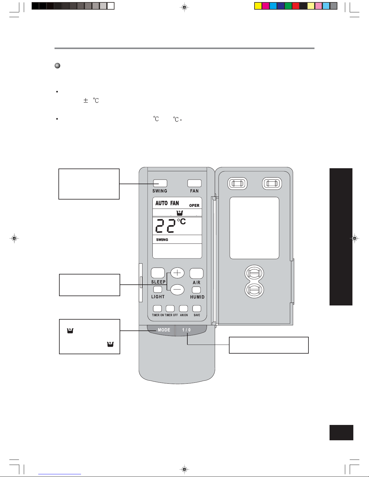
DRY mode operation procedure
If room temp. is lower than set temp., compressor ,outdoor and indoor fan motor stop. If room temp. is
between
2 of set temp., A ir condition er is d rying.I f room temp. is higher th an set temp., it ’s at
COOL mode.
SET TEMP. should be in range of 16
to 30
3.Press SWING button,
the louvers start to rotate automatically, and
stop when repress it.
4.Press TEMP.button,set
suitable SET TEMP.
2.Press MODE button,set
operation mode.
Air speed couldn’t be
changed after the “ ”
being set.
1.Plug in,press 1/0 button,then air
conditioner is turned on.
REMOTE CONTROL OPERATION PROCEDURE
66122452.p65 03-7-15, 17:268
Page 10
9
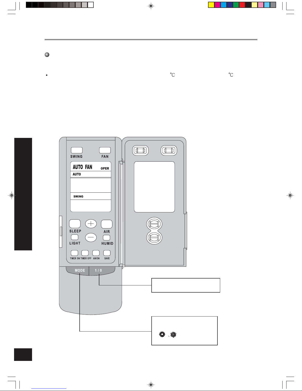
AUTO mode operation procedure
Under Auto mode operation, standard SET TEMP. is 25 for COOL mode and 20 for HEAT
mode.
2.According to room temp.,microcomputer can automatically set
operation mode,so as
for best effect.
1.Plug in,Press 1/0 button, then
air conditioner is turned on.
REMOTE CONTROL OPERATION PROCEDURE
66122452.p65 03-7-15, 17:269
Page 11
10
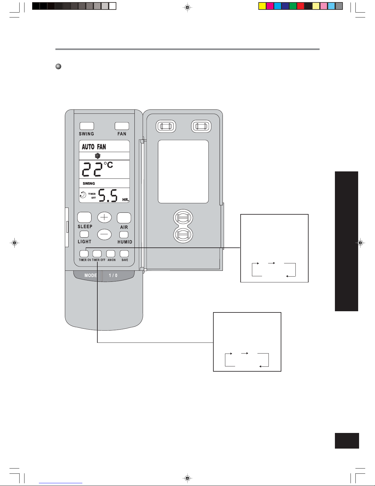
TIMER mode operation procedure
REMOTE CONTROL OPERATION PROCEDURE
TIMER OFF button
At operating, press TIMER
OFF button, set OFF TIME
in range of 0 to 24 hour to
stop the unit automatically.
0 24h
Timer
cancellation
TIMER ON button
At stopping, press TIMER
ON button, set ON TIME in
range of 0 to 24 hour to start
the unit automatically.
0 24h
Timer
cancellation
66122452.p65 03-7-15, 17:2610
Page 12
11
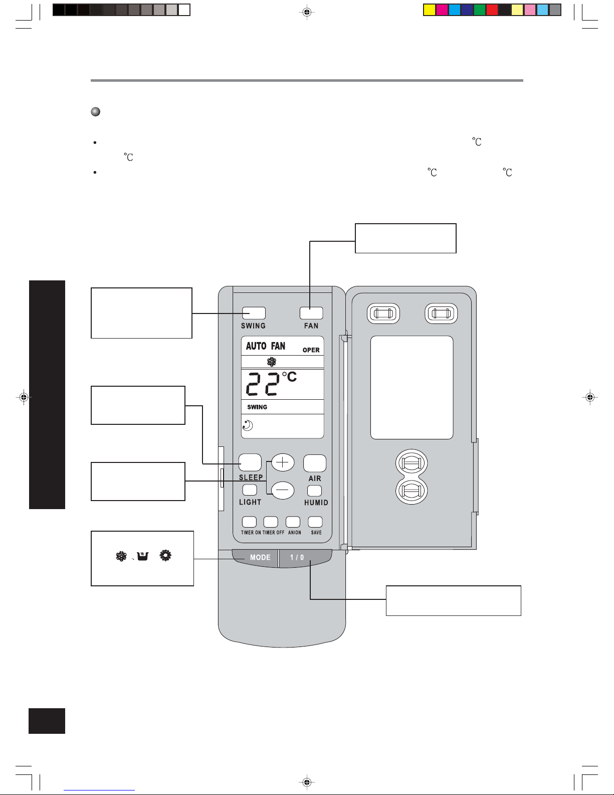
SLEEP mode operation procedure
REMOTE CONTROL OPERATION PROCEDURE
4.Press FAN button, set
fan speed.
5.Press TEMP. but-
ton, set suitable
SET TEMP.
1.Plug in, press 1/0 button,then air
conditioner is turned on.
2.Press MODE button,
set
or op-
eration mode.
3.Press SWING button, the
louvers start to rotate
automatically, and stop
when repress.
6.SLEEP button
Press it to set SLEEP
operation.
As the unit is cooling or drying, if SLEEP operation is set, SET TEMP. would increase 1 in 1 hour
and 2
in 2 hours.
As the unit is heating , if SLEEP operation is set, SET TEMP. would decrease 1
in 1 hour and 2 in
2 hours.
66122452.p65 03-7-15, 17:2611
Page 13
12
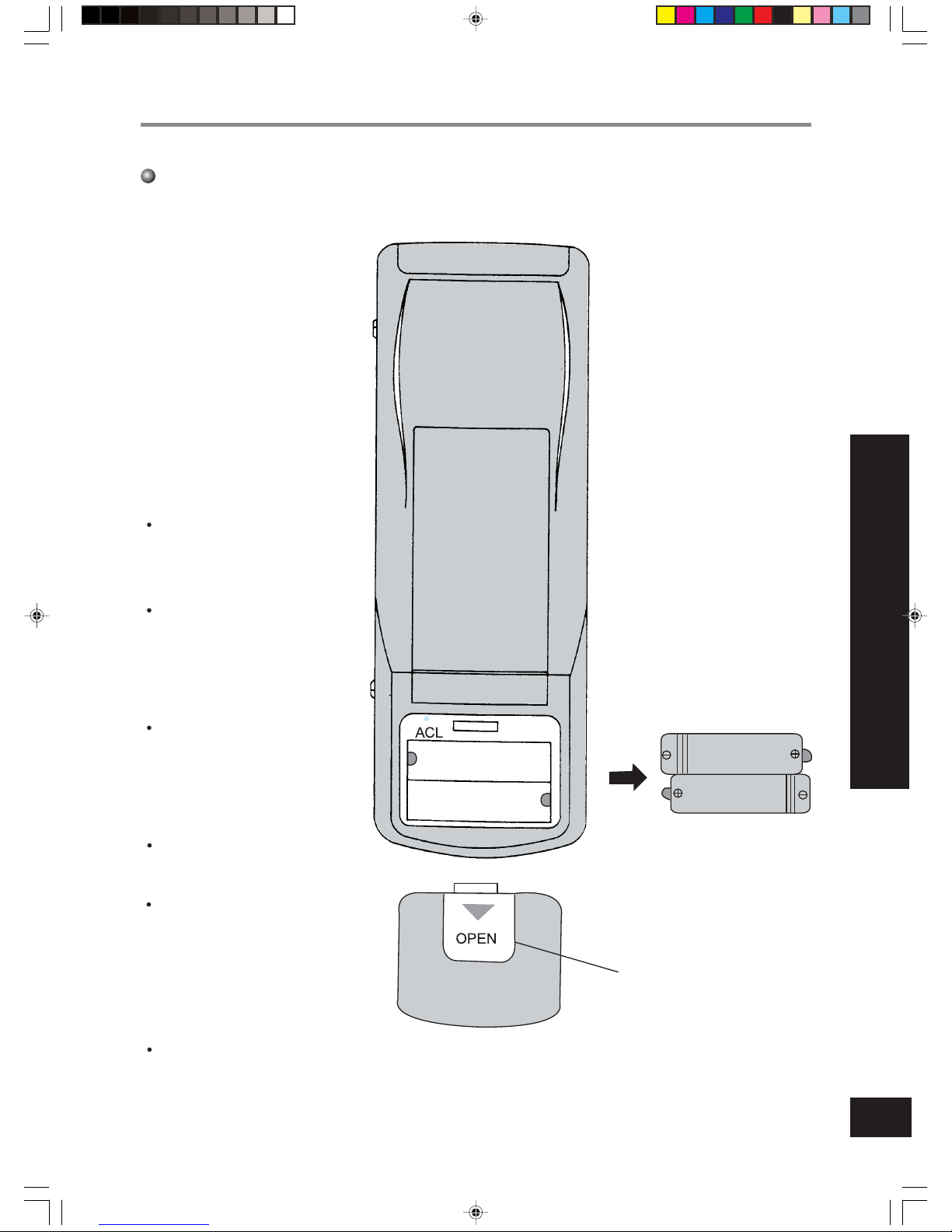
How to insert batteries
1.Remove the cover from the back
of the remote control.
2.Insert the two batteries ( Two 7#
dry - cell batteries ) and press button “ACL”.
3.Re - attach the cover.
NOTE:
Don’t confuse the new
and worn or different
types of batteries.
Remove batteries when
the remote controller is
not in use for a
longtime.
The remote control signal can be received at
the distance of up to
about 10m.
The lifetime of the batteries is about one year.
The remote controller
should be placed about
1m or more away from
the TV. or any other
electric appliances.
Bad batteries are forbidden.
1.Remove the cover
3.Re - attach the cover.
2. Insert the 7
#
batteries
REMOTE CONTROL OPERATION PROCEDURE
66122452.p65 03-7-15, 17:2612
Page 14
13
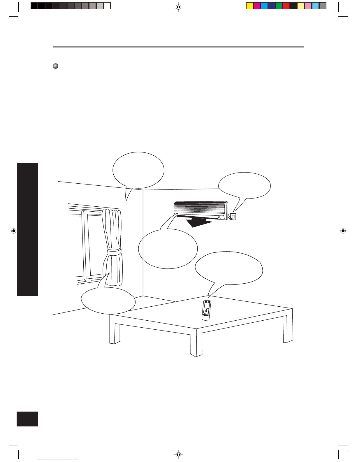
The best operating methods
adjust to the suitable temp. too
cool will do harm
to the health.
pull off the plug
if the unit will be
free in a long
time.
take out the batteries if
the remote controller
will be free within a long
period.
cleaning the air filter seriously and maintaining
the air cleaner carefully.
avoiding directly
lighting and cool
air leaking.
THE BEST OPERA TING METHODS
66122452.p65 03-7-15, 17:2613
Page 15
14
USER NOTICES
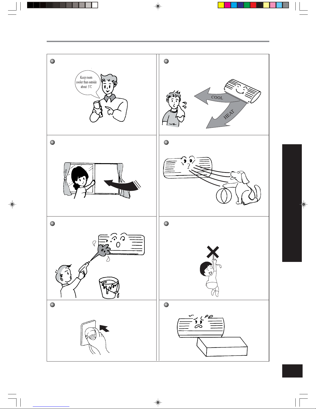
Select the most appropriate temperature. It can
avoid the electricity wasting.
Don’t leave windows and doors open while the air
conditioner is on for a longtime. It can decrease the
air conditioning capacity.
Splashing water on the air conditioner can cause
an electric shock and malfunction.
Air conditioner should be operated with stable
voltage in range of 195-253V 1ph. otherwise, compressor would vibrate terribly to damage refrigeration
system.
The airflow direction can be adjusted appropriately. The louvers can be adjusted downward at heat-
ing operation, and upward at cooling operation.
Don’t blow the wind to animals and plants directly.
It can cause a bad influence to them.
The ground must be connected.
Don’t connect the earth wire to gas or water pipes.
lighting rods or telephone earth lines.
Don’t use the air conditioner for other purposes,
such as drying clothes, preserving foods, etc.
USER NOTICES
66122452.p65 03-7-15, 17:2614
Page 16
15
CAUTION
Turn power off and pull out the power plug before cleaning air conditioner.
Don’t sprinkle water on the indoor unit and the outdoor unit for cleaning.
Wipe the units with a dry soft cloth, or a cloth slightly moistened with water or
cleaner.
(CARE AND MAINTENANCE) CEDURE
Care and Maintenance
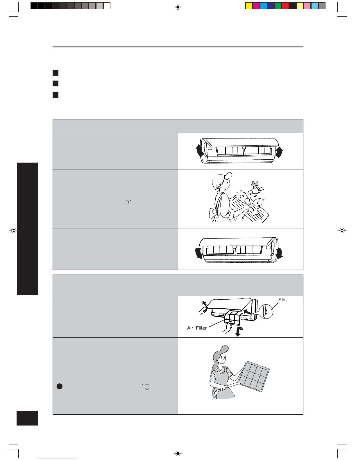
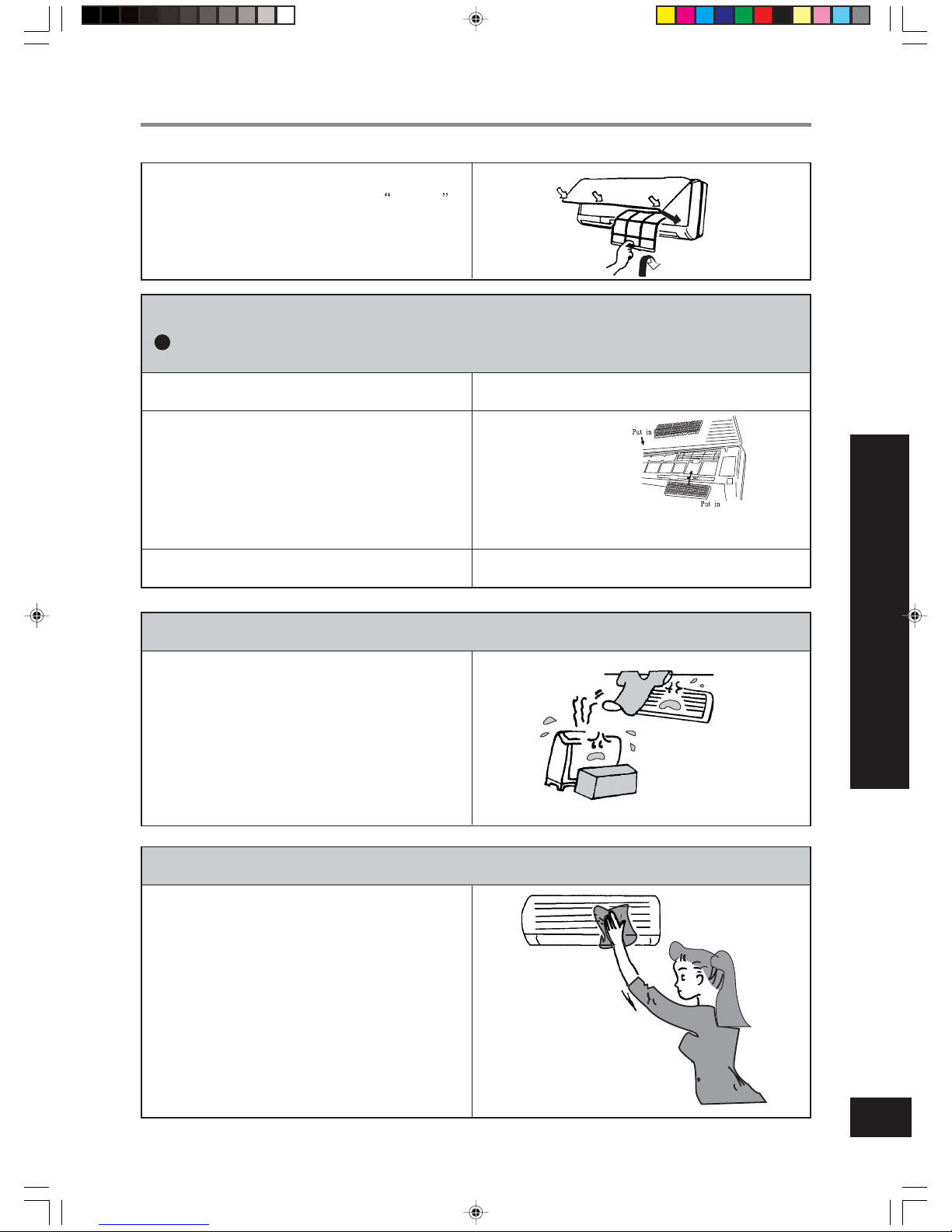
Take down surface panel and washing
1. Pull along the direction of arrows to take down surface
panel.
2. W ashing
Wipe with a cloth slightly moistened with water or
cleanser, and then dry it in the shade.
NOTE:Never use water above 45
to wash the panel, or
it could cause deformation or discoloration.
3. Install surface panel
Cover the surface panel and clasp it.
Cleaning the Air Filters (Recommended once every three months)
1. Open the surface panel, hold the tab of Air Filter and
raise it slightly, and then take it out.
2. Cleaning
T o clean the dust adhering to the filters, you can either
use a vacuum cleaner, or wash them with water and
dry it in the shade.
NOTE:
Never use water above 45 to wash
the filters, or it could cause deformation or discoloration.
66122452.p65 03-7-15, 17:2615
Page 17
16
3.Reinsert the filters
Reinsert the filters with side marked
FRONT
facing forward.
Replacement of Air cleaner
Recommended once every three years, and the alternate filters can be found in the service center.
1.Remove the Air Filters
2.Replace the Air cleaner
Take off the packed bag of Air purifying Filters, and
then put new Filters into the Filter frame.
3.Re-insert the filters
(Refer to the first step of “cleaning the Air Filters”)
Air cleaner
NOTE:Be careful not to injure yourself on the fins
(Refer to the third step of “cleaning the Air Filters”)
Preparation before use
1.Be sure that nothing obstructs the air outlet and intake
vents.
2.Check that whether ground wire is properly connected
or not.
3.Replace filters if necessary.
4. Replace the batteries if necessary.
Maintain after use
1.Clean filters and other parts.
2.Turn main power off.
3.Clear dust from the outdoor unit.
4.If there is any rust in the outdoor unit, this should be
painted over to prevent it from spreading.
(CARE AND MAINTENANCE) CEDURE
66122452.p65 03-7-15, 17:2616
Page 18
17
Trouble shooting
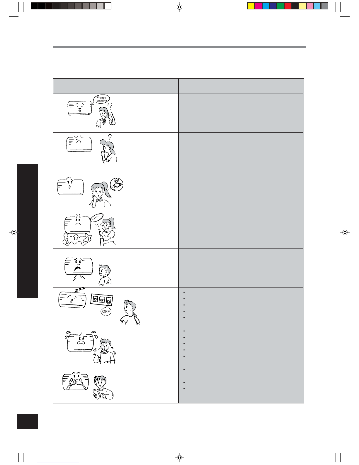
Check the following points before requesting on service center if the malfunction persist, it saves
your time and money.
TROUBLE SHOOTING
Phenomenon
Indoor unit does not
operate immediately
when the air conditioner is restarted.
There’s unusual
smell blowing from
the outlet after operation is started.
Sound of water flow
can be heard during
operation.
Mist is emitted during cooling operation.
Creaking noise can
be heard when start
or stop the unit.
Air conditioner does
not operate at all.
Cooling (Heating) efficiency is not good.
Wireless remote controller is not available.
Trouble Shooting
Once the air conditioner is stopped, it will not operate in
approximately 3 minutes to protect itself.
This is caused by the odors in the room which have been
breathed into the air conditioner.
This is caused by the refrigerant flowing inside the unit.
Because the air of the room is cooled down rapidly by the
cold wind and it looks like the fog.
This is caused by the deformation of plastic due to the
change of temperature.
Has the power been shut down?
Is the wiring loose?
Is the leakage protection switch in operation?
Is voltage higher than 253V or lower than 195V?
Is TIMER ON in operation?
Is SET TEMP. suitable?
Is air inlet or outlet obstructed?
Are air filters dirty?
Is indoor fan speed set at low speed?
Is there any other heat sourse in your room?
Is the remote control unit out of effective distance to the
indoor unit?
Replace the worn batteries of wireless remote controller.
Are there any obstructions between the wireless remote
controller and the signal receptor?
66122452.p65 03-7-15, 17:2617
Page 19
18
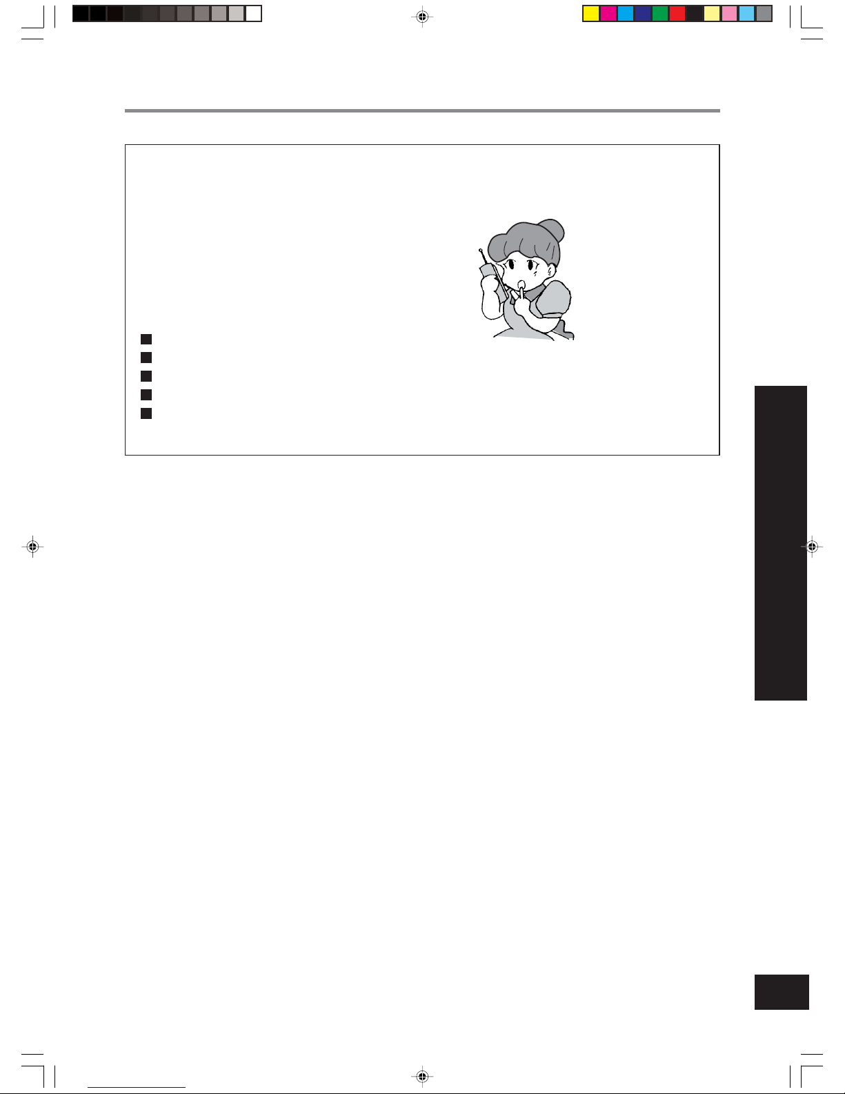
Immediately stop all operations and plug out, contact with service center in
following situations.
Unusual noise can be heard during operation.
Power fuse or switch often breaks.
Carelessly splash water or something into air conditioner.
Electrical lines and power plug are very hot.
Wind blowing from the outlet smells terrible during operation.
TROUBLE SHOOTING
Trouble shooting
NOTE:
Equipment subject to notification to or consent by the supply authority before
connection to the system (consent by the supply authority may be requested for high power appliances which are intended to be used only in systems having impedances
considerably lower than the reference impedance. General consent may declared for use
of a type of appliance in a defined part of the supply system):
1. Equipment intended exclusively for professional purposes;
2. Appliances and equipment without automatic control means;
3. Appliances producing less than one voltage change per hour;
4. Appliances producing more than 1800 voltage changes per minute;
5. Disturbances caused by manual switching.
66122452.p65 03-7-15, 17:2618
Page 20
19
TECHNICAL SPECIFICATIONS
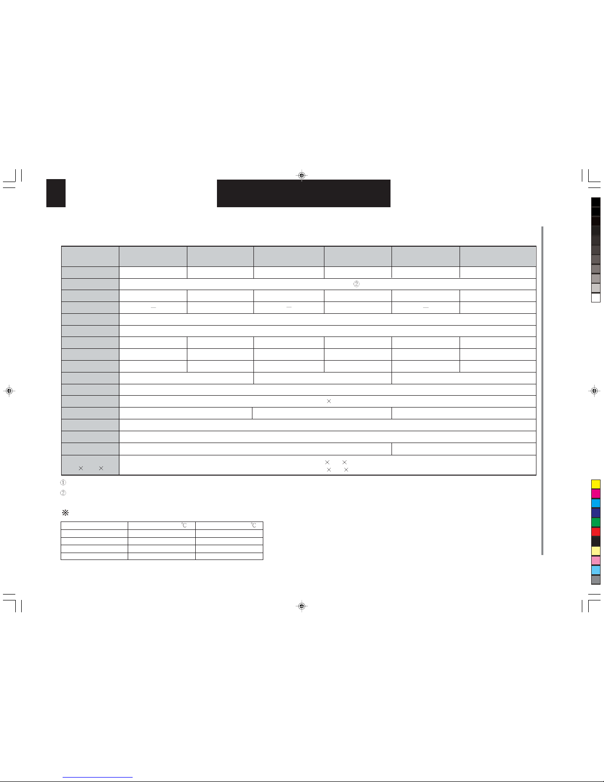
Technical specifications
All above should be changed without notice, there are latest and accurate specifications on the nameplate of your air conditioner.
When the unit is restarted after it was stopped, it can automatically resume in its most latest running mode, and the outdoor unit starts a little bit later.
Model
Functions
Accessory
Cooling capacity (W)
Heating capacity (W)
Power supply
Frequence
Cooling/Heating rated current
Maximum input current
Cooling/Heating rated power
Recyling air volume
Refrigerant
Waterproof level
Noise(Indoor/outdoor)dB(A)
Climate type
Anti-electric shock protection
Weight(kg)
Indoor unit/
outdoor unit
Dimension(cm)
(Width height depth)
Working temperature range
Maximum cooling
Minimum cooling
Maximum heating
Minimum heating
Indoor side DB/WB( )
32/23
21/15
27/20/-
Outdoor side DB/WB(
)
43/26(T1)
21/-
24/18
-5/-6
I
50Hz
Indoor 25.0 77.0 18.0
Outdoor 84.8
54.0 32.0
40/56 dB(A)
480m3/h
IP
4
230V~
400m3/h
450m
3
/h
32/51 dB(A) 36/52 dB(A)
Cool
2000W
3.26/-A
4.1A
750/-W
Cool Heat
2000W
2400W
3.26/3.43A
4.1A
750/790W
Cool
2500W
4.35/-A
4.8A
1000/-W
Cool Heat
2500W
3100W
4.35/4.57A
5.8A
1000/1050W
Cool
3200W
5.57/-A
6.4A
1280/-W
T1
8.5/40 kg
8.5/32 kg
Cool Heat
3200W
3800W
5.87/6.52A
8.5A
1350/1500W
R22
Memory function (show in
)
66122452.p65 03-7-15, 17:2619
Page 21
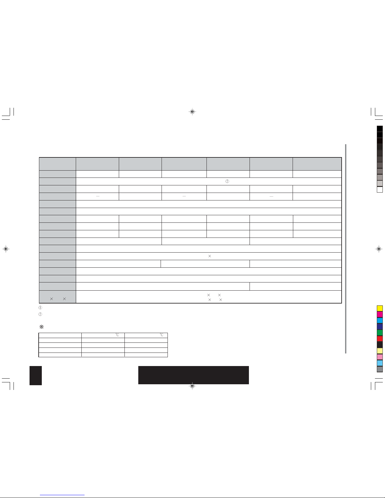
20
Technical specifications
All above should be changed without notice, there are latest and accurate specifications on the nameplate of your air conditioner.
When the unit is restarted after it was stopped, it can automatically resume in its most latest running mode, and the outdoor unit starts a little bit later.
Model
Functions
Accessory
Cooling capacity (W)
Heating capacity (W)
Power supply
Frequence
Cooling/Heating rated current
Maximum input current
Cooling/Heating rated power
Recyling air volume
Refrigerant
Waterproof level
Noise(Indoor/outdoor)dB(A)
Climate type
Anti-electric shock protection
Weight(kg)
Indoor unit/
outdoor unit
Dimension(cm)
(Width height depth)
Working temperature range
Maximum cooling
Minimum cooling
Maximum heating
Minimum heating
Indoor side DB/WB( )
32/23
21/15
27/20/-
Outdoor side DB/WB(
)
43/26(T1)
21/-
24/18
-5/-6
I
50Hz
Indoor 25.0 77.0 18.0
Outdoor 84.8
54.0 32.0
40/56 dB(A)
460m3/h
IP
4
230V~
420m3/h
420m
3
/h
36/52 dB(A) 3/52 dB(A)
Cool
2000W
3.6/-A
5A
830/-W
Cool Heat
2000W
2400W
3.6/3.5A
5A
830/800W
Cool
2500W
4.4/-A
5.9A
1000/-W
$6+&6
Cool Heat
200W
200W
4.4/4.6A
5.9A
1000/1050W
Cool
3200W
5.9/-A
7.4A
1350/-W
T1
8.5/40 kg
8.5/32 kg
Cool Heat
300W
3800W
5.9/6.1A
.A
10/100W
$6+&6
R407C
Memory function (show in
)
TECHNICAL SPECIFICATIONS
66122452.p65 03-7-15, 17:2620
Page 22
21
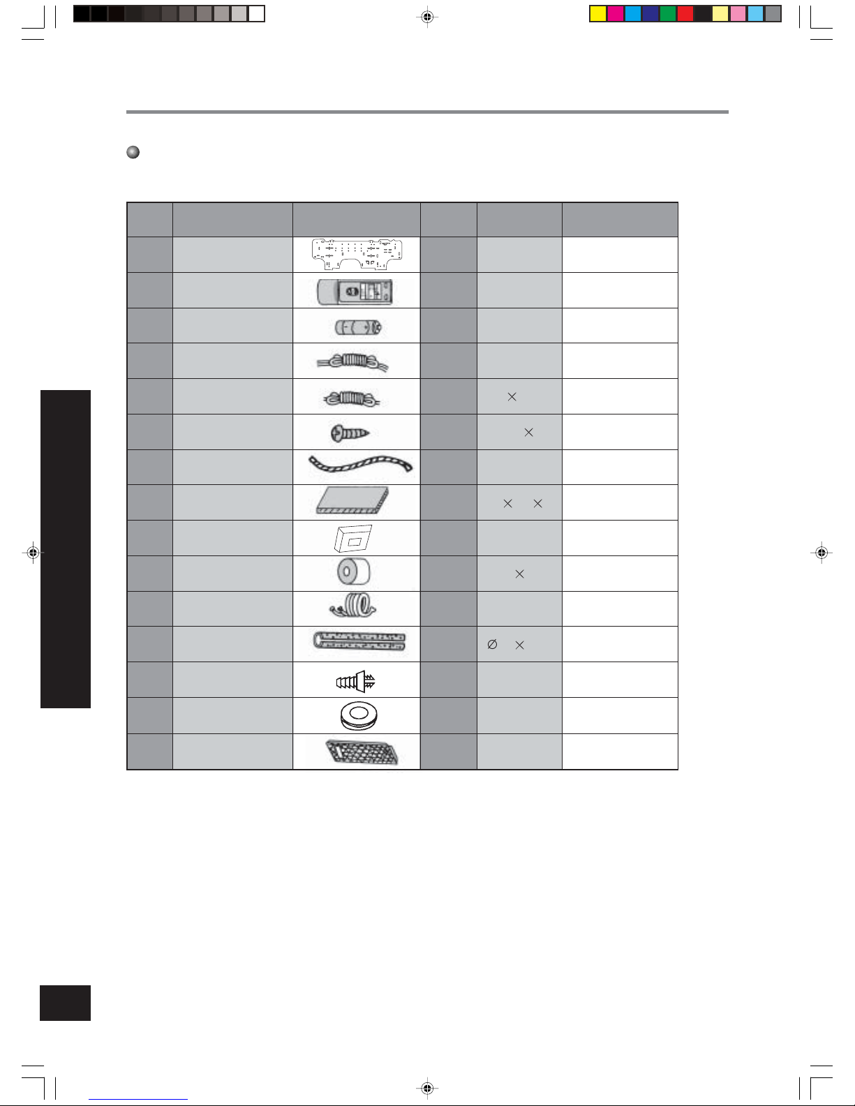
Accessories (Check that all accessory parts are present before installation)
* Be sure to use the exclusive accessories list above in the installation,or it will lead to water leakage, electric
shock, fire, etc.
Accessories and Installation diagram
ACCESSORIES AND INSTALLA TION DIAGRAM
No.
1
2
3
4
5
6
7
8
9
10
11
12
13
14
15
Part name
Rear panel
Battery
Power connection cord
Control cord
Tapping screw
Plastics drain hose
Gum type sealer
Piping- hole sleeve
Wrapping tape
Connection piping
Thermal insulation hose
outdoor drain elbow
outdoor drain stem
Air cleaner
Wireless remote
controller
Qty
1
1
2
1
1
10
1
1
2
2
1
1
1
2
2
7
#
1.5V
4
0.75
ST4.2
25
L=2m
120
65 25
30
10
35
500
Heat pump type only
Fix the rear panel
Diagram Specification Memo
Packaged with
connection piping
Packaged with
connection piping
Packaged with
connection piping
Packaged with
connection piping
Packaged with
indoor unit
Heat pump
type only
Heat pump
type only
66122452.p65 03-7-15, 17:2621
Page 23
22
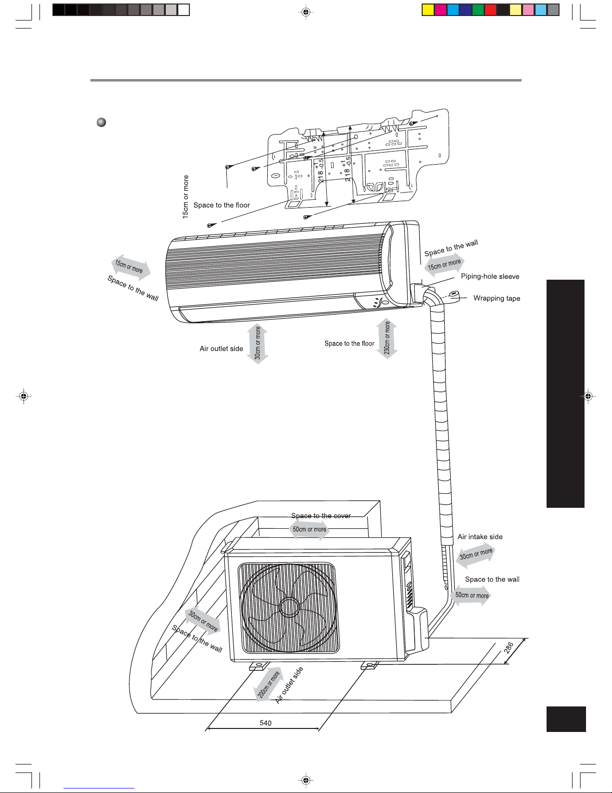
ACCESSORIES AND INSTALLATION DIAGRAM
Installation dimension diagram
IMPORTANT NOTES
The installation must be done by trained and qualified service personnel with reliability according to this manual.
Contact with service center before installation to avoid the malfunction due to unprofessional installation.
When picking up and moving the units, you must be guided by trained
and qualified personnel.
The air conditioner should be connected to the earth,correctly,if
not,contact with the service center.
*
*
*
66122452.p65 03-7-15, 17:2622
Page 24
23
Installation location
Indoor unit
1.The inlet and outlet should not be covered so that the outflow air can reach all parts of the room.
2.Install in a location where is easy to connect to the outdoor unit.
3.A location from which the condensation water can be drained out conveniently.
4.Avoid a location where there is heat source, high humidity or inflammable gas.
5.Install in a location where is strong enough to withstand the full weight and vibration of the unit.
6.Be sure that the installation conforms to the installation dimension diagram.
7.Be sure to leave enough space to allow access for routine maintenance.The height of the installed location should be
2.3m or more from the floor.
8.Install in a location where is lm or more away from other electric appliances such as television, audio device,etc.
9.Select location where is easy to remove and clean the filter.
10.Do not use the unit in the immediate surroundings of a laundry,a bath,a shower or a swimming pool.
Outdoor unit
1.Select location from which noise and outflow air emitted by unit will not disturb neighbors.
2.Select location where ventilate freety.
3.The inlet and outlet should not be covered.
4.The location should be able to withstand the full weight and vibration of the outdoor unit.
5.There should be no danger of flammable gas or corrosive gas leaks.
6.Be sure that the installation conforms to the installation dimension diagram.
NOTE:
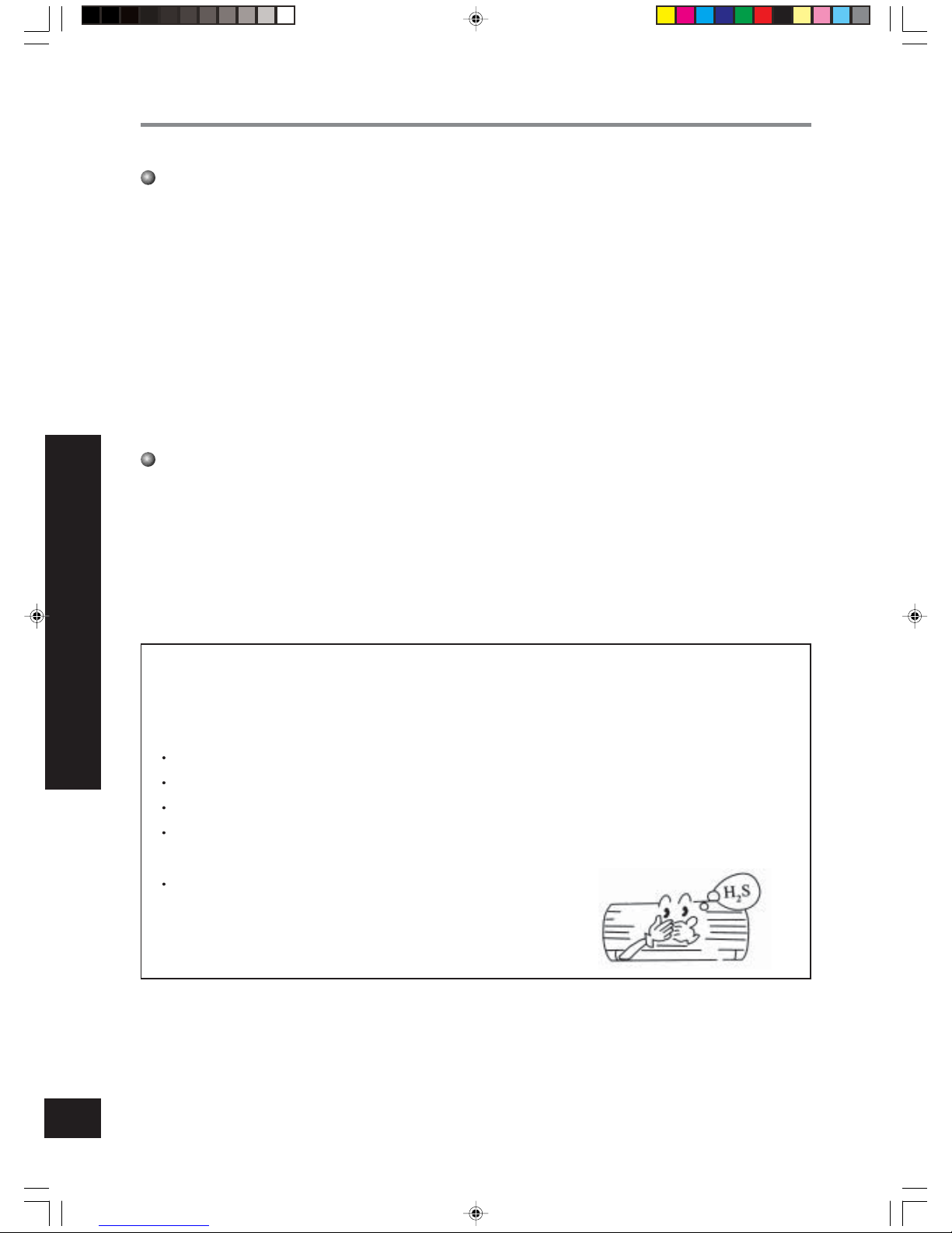
Install in the following place may cause malfunction. If it is unavoidable, contact with service
center please.
Place where oil (machine oil ) is used.
The place where a lot of salinities such as coast exists.
Place where a sulfured gas such as the hot spring zones is generated.
Place where high - frequency waves are generated by radio equipment, welders and medical
equipment.
Other place with special circumstance.
INSTALLATION LOCATION
66122452.p65 03-7-15, 17:2623
Page 25
24
INSTALL THE INDOOR UNIT
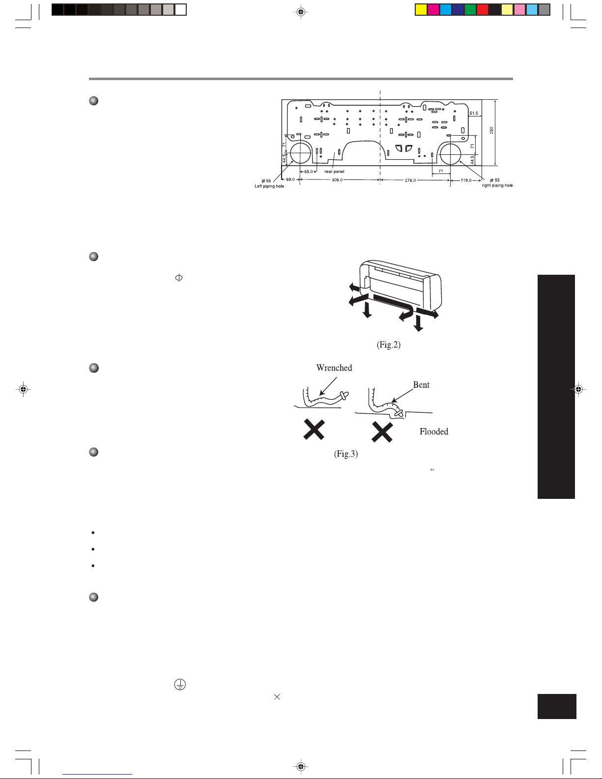
Install the rear panel
1.For well draining,make the rear panel horizontally and then appreciably lower the left
side of the rear panel because the drain hose
is on the left side..
2.Fix the rear panel on the selected location with
screws supplied with the unit.
3.Be sure that the rear panel has been fixed
firmly enough to withstand the weight of an
adult of 60kg, furthermore, the weight should
be evenly shared by each screw.
Install the indoor unit
Install the drain hose
1.For well draining, the drain hose should be placed
at a downward slant.
2.Do not wrench or bend the drain hose or flood its
end by water.
Install the connection pipes
Connect the connection pipes with the relevant union pipes of the indoor unit (Shown in P26 Install the connection
pipes” ).
Install the piping hole
NOTE:
Connect the connection pipes with the indoor unit firstly and the outdoor unit secondly.
Be careful in bending the connection pipes, or you will damage the pipes.
If the tightening torque is too great in tightening the flare nuts, leakage will happen.
Electrical wiring
1.Open the surface panel.
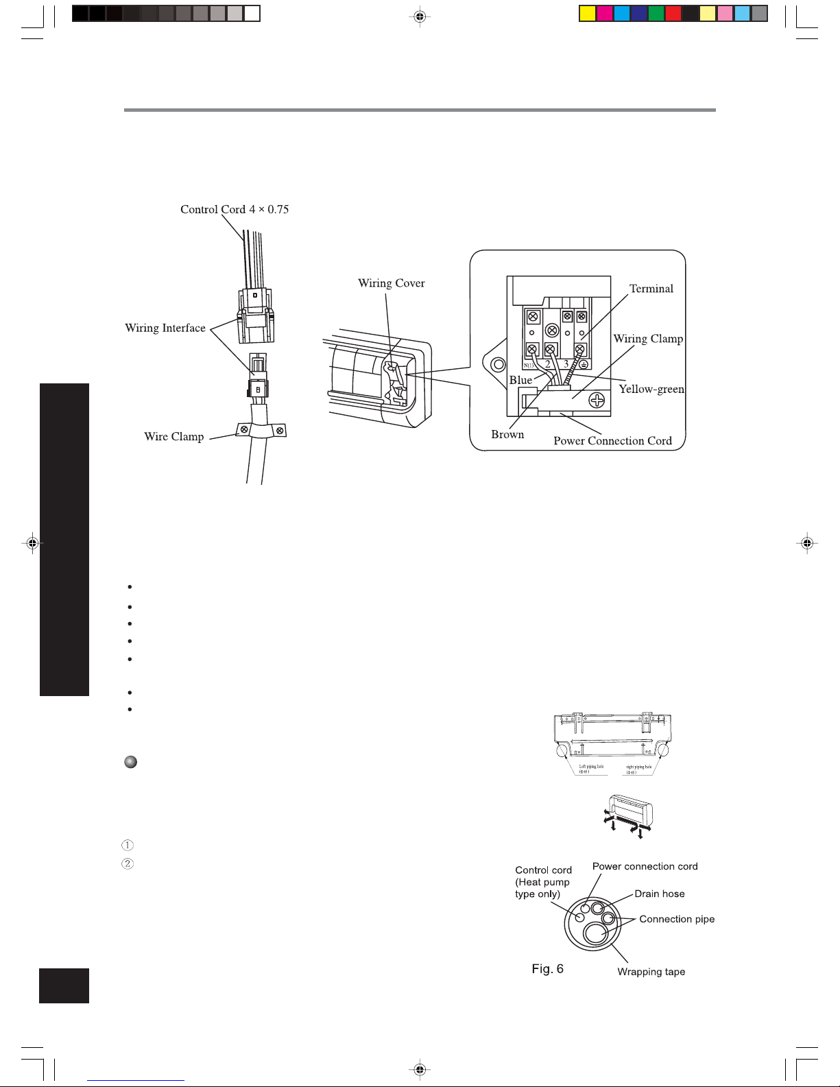
2.Remove the wiring cover(Fig.4).
3.Route the power connection cord from the back of the indoor unit and pull it toward the front through the wiring hole for
connection.
4.Connect the blue wire of the power connection cord to the terminal “N(1)”, the brown one to “2”, and the yellow- green
one ( earth wire ) to “ ” as shown in Fig.4.
5. For the heat pump type, connect the control cord ( 4
0.75) to the indoor unit through wiring interface shown in Fig.4,and
clamp the connected cord on the chassis.
1.Make the piping hole ( 55) in the wall at a slight
downward slant to the outdoor side. The center of
the hole should be determined refer to Fig.1.
2.Insert the piping-hole sleeve into the hole to prevent the connection piping and wiring from being
damaged when passing through the hole.
66122452.p65 03-7-15, 17:2624
Page 26
25
6.Reassemble the clampand wiring cover.
7.Recover the surface panel.
Install the indoor unit
1.When routing the piping and wiring from the left or right side of the indoor unit , cut off the tailings from the pipe holder in necessary (shown in
Fig.5).
Through the hole when routing the wiring only.
Cut off the tailings l when routing both the wiring and piping.
2.Wrap the piping and wiring and pull them through the cut - off - tailings
hole (shown in Fig.6).
3.Hang the 2 mounting slots of the indoor unit on the upper tabs of the real
panel and check if it is firm enough.
4.The height of the installed location should be 2.3m or more from the floor.
INSTALL THE INDOOR UNIT
Install the indoor unit
Fig.4
NOTE:
All the electrical work must be done by qualified personnel according to the local rules and this manual.
The rated voltage and the exclusive circuit must be used.
Leakage circuit - breaker must be installed.
Please use specified fuse.
If the power supply cord of the unit is damaged, it must be replaced by the manufacturer or its service agent or
a similarly qualified person in order to advoid a hazard.
The diameter of power cord should be large enough.Use the exclusive wire to replace the damaged wire.
Wiring work should conform to relative standard.
66122452.p65 03-7-15, 17:2625
Page 27
26
INSTALL THE OUTDOOR UNIT
Install the outdoor unit
Install the connection pipe
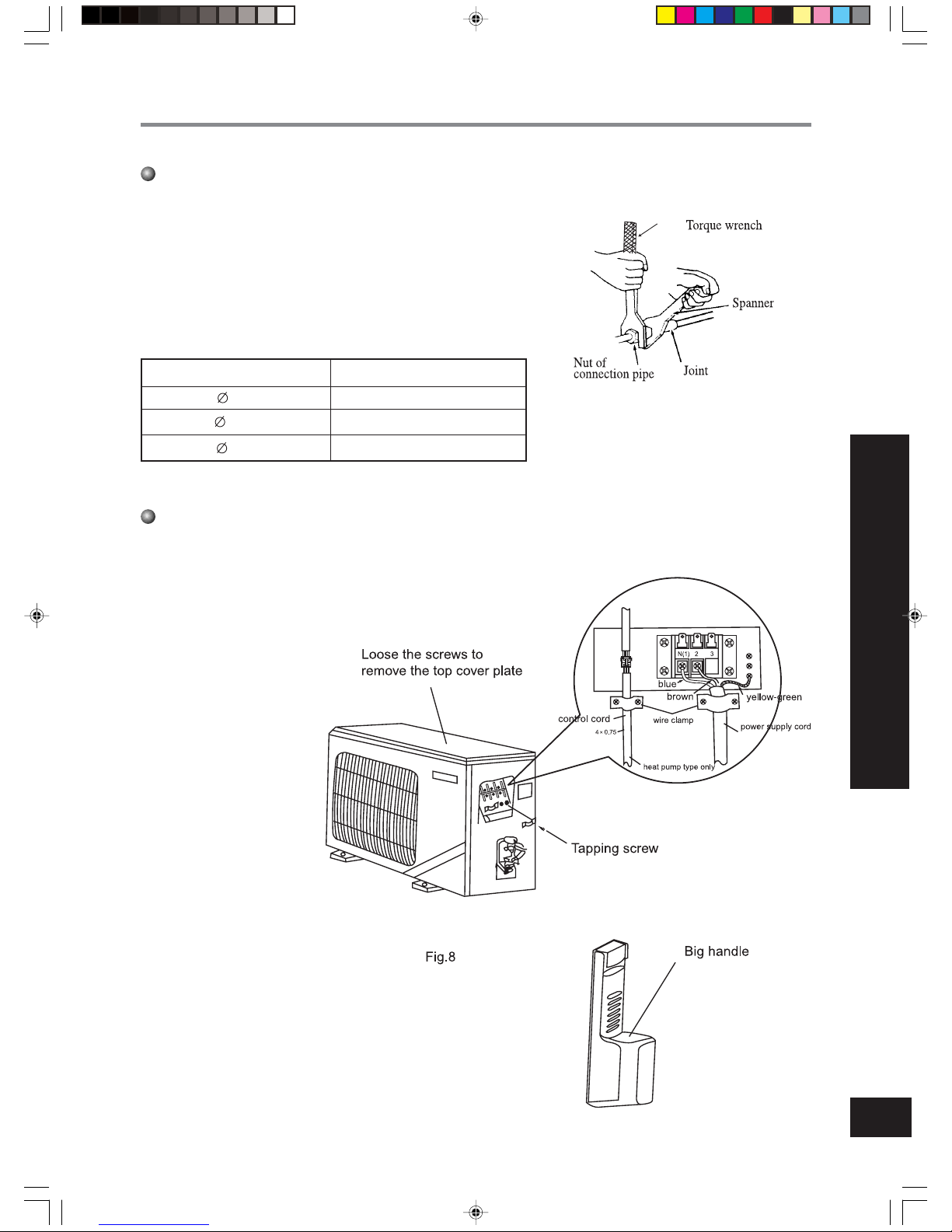
1.Align the center of the piping flare with the relevant valve.
2.Screw in the flare nut by hand and then tighten the nut with spanner
and torque wrench refer to the diagram at right.
NOTE:
Wrong wiring connection will cause electrical mal-
function.
Do not pull the wire when fixing it with wire clamp.
Do not let the wire too loose in the outdoor unit.
Note: Exceeding tightening torque will damage the
flare surface.
Tightening torque table
Electric wiring connection
2.Remove the wire clamp and
connect the end of the power
connection cord with screws
to the wiring terminal board.
Be sure that the wiring connection is in accordance
with the indoor unit’s.
3.Fix the wiring with wire
clamp and joint the relevant
wiring interfaces.
4.Make sure that the wiring
has been connected firmly.
5.Reassemble the big handle.
6.If power cord have not plug,
an all-pole disconnection air
switch which have a contact
separation of at least 3mm
in all pole is need.
Fig.7
1.Disassemble the big handle.
Hex nut diameter (mm)
6
9.5
12
Tightening torque(N.m)
15~20
31~35
50~55
66122452.p65 03-7-15, 17:2626
Page 28
27
Air purging and leakage test
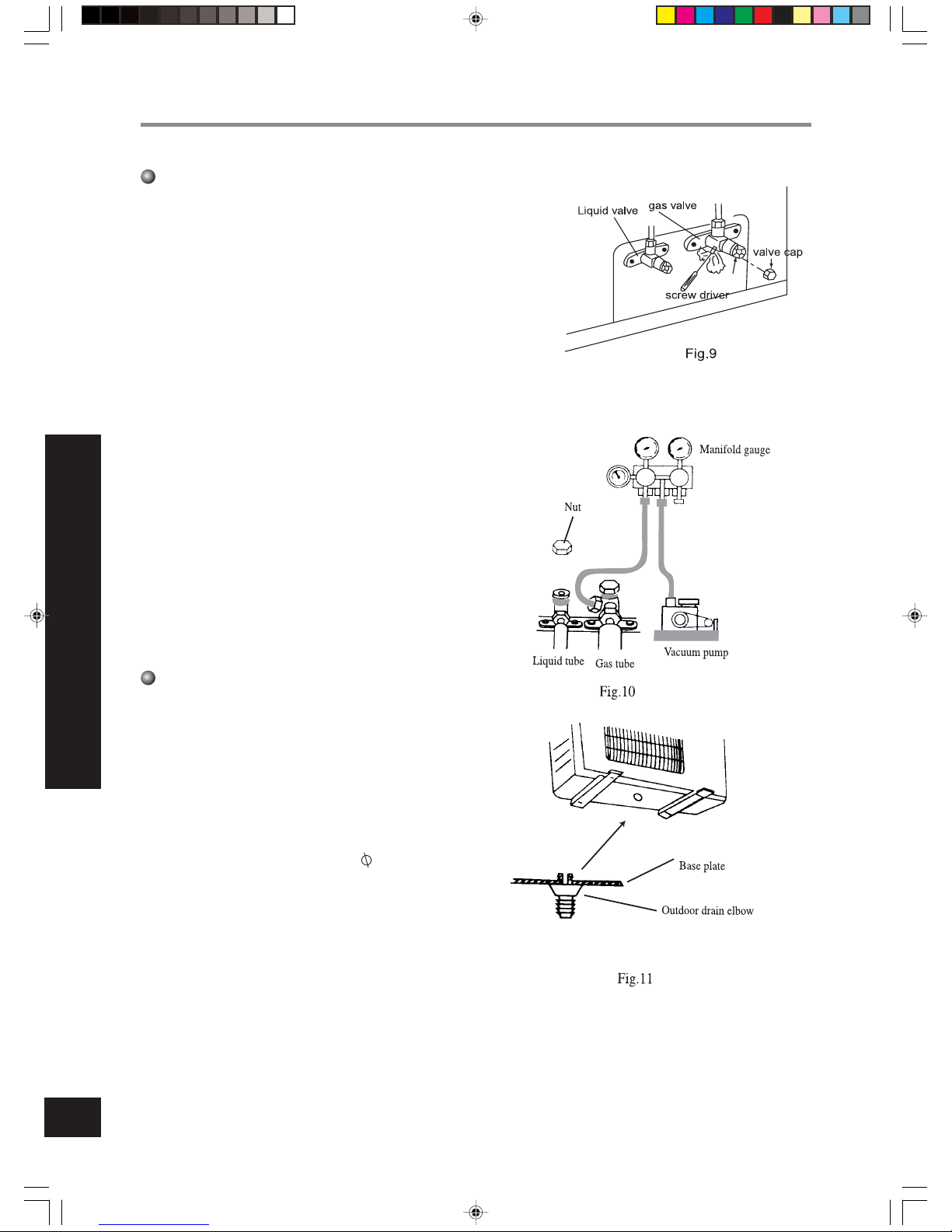
1.Remove the flare nuts from the cut - off valves of the outdoor unit.
2.Align the center of the piping flare with the relevant valve, and screw
in the flare nut about 3~4 turns by hand.
3.Tighten the flare nut with spanner and torque wrench.
4.Remove the valve caps of the gas valve and liquid valve and the service port nut.
5.Loosen the valve stem of the liquid valve with a hex wrench.
6.Push the check valve core of the gas valve to discharge air and moisture remaining in the refrigerant system.
7.Stop pushing the valve core as soon as the refrigerant starts to be
discharged, and reinstall the service port nut.
8.Open the liquid valve and gas valve entirely (shown in Fig.9).
9.Tighten the valve caps and test leakage at all joints of the piping (both
indoor and outdoor) with liquid soap or leak detector.
10.If possible, discharge air and moisture remaining in the refrigerant
system with a vacuum pump. (shown in Fig.10)
Outdoor condensation drainage
(Heat pump type only)
When the unit is heating or defrosting,the waste
water formed in the outdoor unit can be drained out
reliably through the drain hose.
Installation:
Install the outdoor drain elbow in the 25 hole on
the base plate as shown in Fig.11, and joint the drain
hose to the elbow, so that the waste water formed in
the outdoor unit can be drained out to a proper place.
INSTALL THE OUTDOOR UNIT
Install the outdoor unit
66122452.p65 03-7-15, 17:2627
Page 29
28
Test operation and check after installation
Check after installation
Items to be checked
Has the air coditioner been fixed firmly?
Have you done the refrigerant leakage test?
Is heat insulation sufficient?
Does the unit drain well?
Is the voltage in accordance with the rated voltage marked on the nameplate?
Is the electrical wiring and piping connection installed correctly and securely?
Has the unit been connected to a secure earth
connection?
Is the power cord specified?
Has the inlet and outlet been covered?
Has the length of connection pipes and the refrigerant capacity been recorded?
Possible malfunction
The unit may drop, shake or emit noise.
It may cause insufficient refrigerating
capacity.
It may cause condensation and dripping.
It may cause condensation and dripping.
It may cause electric malfunction or damage the part.
It may cause electric malfunction or damage the part.
It may cause electrical leakage.
It may cause electric malfunction or dam-
age the part.
It may cause insufficient refrigerating
capacity.
The refrigerant capacity is not accurate.
Situation
TEST OPERATION AND CHECK AFTER INSTALLATION
Test operation
1. Before test operation
(1)Do not switch on power before installation is finished
completely.
(2)Electric wiring must be connected correctly and
securely.
(3) Cut - off valves of the connection pipes should be
opened.
(4)All the impurities such as scraps and thrums must be
clear from the unit.
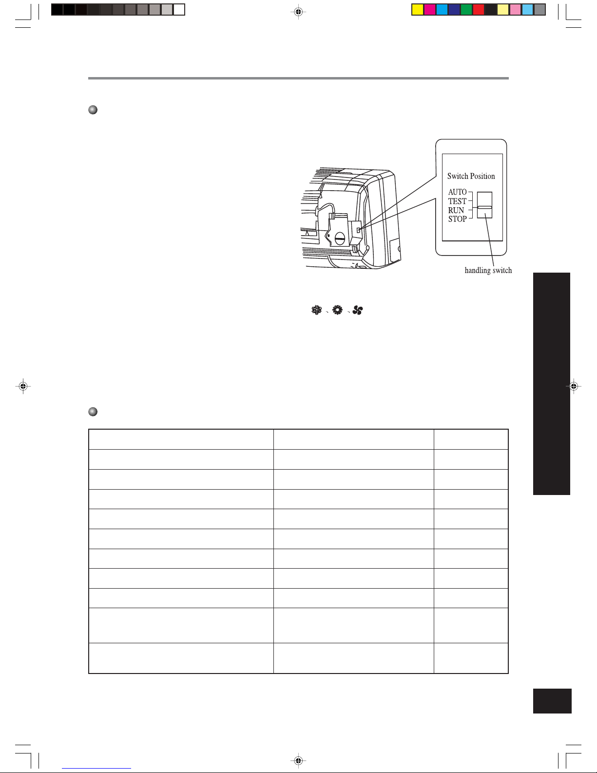
(5)Open the surface panel and set the handling switch to
“RUN” mode.
2. Test operation method
(1)Switch on power and press “1/0” button on the remote controller.
(2)Press “MODE” button and check the operation condition of
modes.
(3)Forced operation.
Act as following when the remote controller can not be used:
(1)At stopping, set the handling switch to “AUTO” mode, the the unit will automatic run in the mode selected by the
microcomputer system according to surrounded temperature.
(2)At operation, set the handling switch to “STOP” mode to turn off the unit.
66122452.p65 03-7-15, 17:2628
Page 30
29
CONTENTS
Thank you for choosing this Air conditioner, please keep this owner’s manual carefully for consultation.
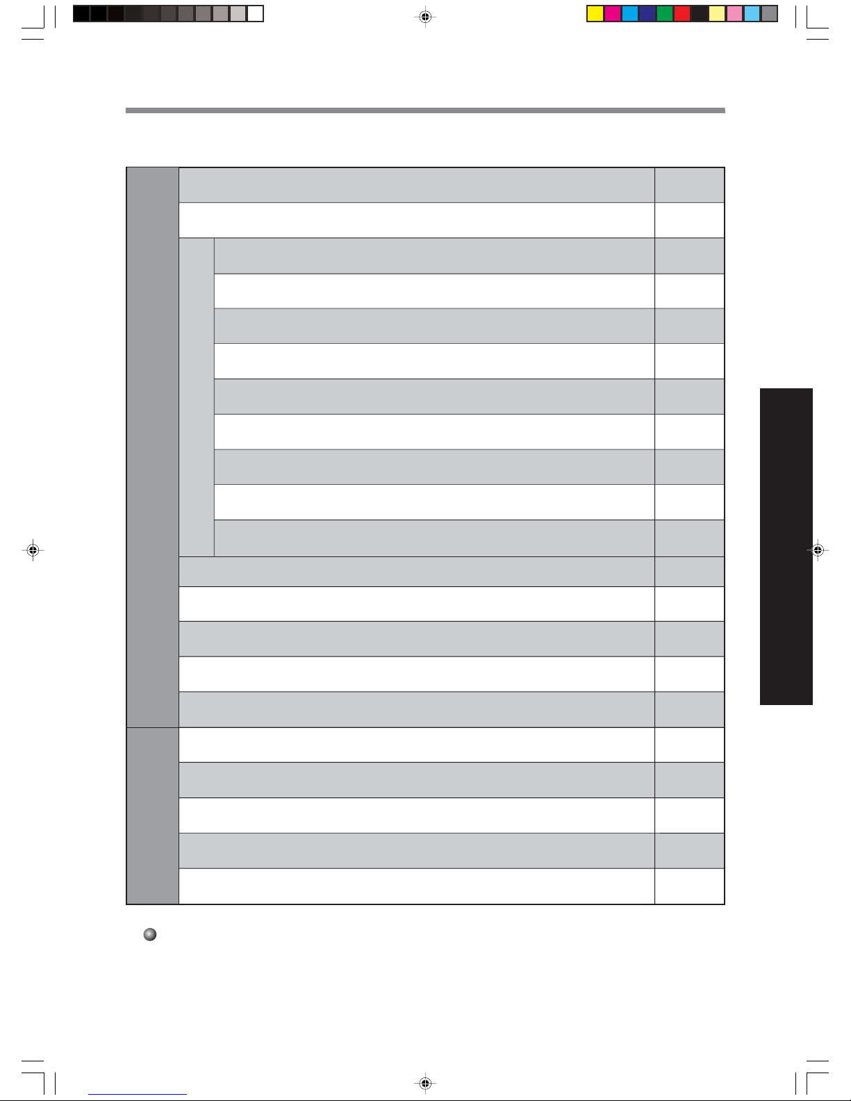
CONTENTS
1
3
4
5
6
7
8
9
10
11
12
13
14
15
17
19
21
23
24
26
28
Operation and maintenanceInstallation
The instructions before use
Name and function of each part
Name and Function-Remote control
Name and Function-Remote control(Remove the cover)
COOL mode operation procedure
HEAT mode operation procedure
DRY mode operation procedure
AUTO mode operation procedure
TIMER mode operation procedure
SLEEP mode operation procedure
HOW to insert batteries
The best operating methods
User notices
Care and Maintenance
Trouble shooting
Technical specifications
Accessories and Installation diagram
Installation location
Install the indoor unit
Install the outdoor unit
Test operation and check after installation
Remote control operation procedure
66122452.p65 03-7-15, 17:2629
 Loading...