

MixFlo Pro Series,MixFlo Pro MFLP100,MixFlo Pro FAN2049,MixFlo Pro MFLP125,MixFlo Pro FAN2050,MixFlo Pro MFLP150,MixFlo Pro FAN2051
SImx MixFlo Pro Series,MixFlo Pro MFLP100,MixFlo Pro FAN2049,MixFlo Pro MFLP125,MixFlo Pro FAN2050,MixFlo Pro MFLP150,MixFlo Pro FAN2051 Installation Instructions Manual
INSTALLATION INSTRUCTIONS
PRO-SERIES
IMPORTANT
• Isolate the mains supply before making any electrical connections.
This system should be installed by a qualied electrician.
•
• The external grille must be tted at all times.
• Fan should only be installed by xed wiring (unless equipped with plug).
• The appliance is not intended for use by young children or inrm persons
without supervision.
• Young children should be supervised to ensure that they do not play with
the appliance.
• Precautions must be taken to avoid the back-ow of gases into the room
from the open ue of gas or other open-re appliances when mounted in
outside windows or walls.
MixFlo PRO SERIES IN-LINE FAN KITS
Thank you for selecting one of our Pro Series mixed ow in-line fan kits.
Please read all instructions before commencing installation.
1. The interior grille comes in two parts, the chassis (or spigot) and the fascia.
The best way to extract steam from the bathrooom is to locate the grill in the
ceiling centred above the shower/bath area. For general bathroom extraction
the grill can be installed centred in the room. Cut hole in ceiling for grill
(See Fig 1. for hole sizing).
If using the gib xing clip option the white fastening wedge-type clips must be
tted onto the grille body – the closed end of the ‘V’ points towards the rear of
the grille. Start the screw through the ange on the grille into the screw-hole in
the clip with two or three turns. If the ceiling or wall lining is thicker than standard
12mm board it may be necessary to use longer screws than those supplied.
When tted, fasten the ducting onto the grilles using the tape supplied.
Push the grille fully into the hole and then use a screwdriver to push the clips
up into the hole. Once through the hole the clips will spring open and can then be
tightened with the screw to pull back down onto the rear side of the
gib. Tighten until rm only, do not over-tighten.
Fit the fascia onto the chassis. Note there are two lugs on the rear rim of the
egg-crate insert which locate into corresponding slots in the black housing,
adjacent to the ends of the bridge-piece in the housing. This ensures the egg-
crate pattern is lined up with the bridge-piece correctly.
MixFlo Pro Series is proudly distributed by Simx Limited
Technical Support (09) 259 1662
e: sales@simx.co.nz | www.simx.co.nz
reserve the right to change specication without prior warning
We
PUB1316 iss:01 01/15
2. Select a suitable place for the fan to be installed in the ceiling cavity centrally in
the ducted system. It is recommended to suspend your MixFlo fan from the
ceiling framing with strapping (DCT2299) or fan mounting brackets (FAN0015)
to minimise sound levels resonating through ceiling framing (Fig. 6).
Note:
• The discharge end of the Fan unit is the end where you can see the fan blade
clearly. There is also an arrow on the unit showing airow direction.
• Excessive ducting and sharp bends lower the fans performance.
Before cutting, assure ducting is long enough with gradual bends.
3. For the exterior grille there are two options, either a weatherproof cowl or a
xed grille. Select a suitable position either in the soft or on an outside wall for
your chosen grille. Carefully remove the grille insert/cowl from its housing by
levering gently at the sides with a small screwdriver. Cut hole as per Fig. 1.
4. Attach one end of the exible duct to the spigot of the inside grill with the duct tape
provided. Pull ducting to fan, cut, and tape.
Attach remaining ducting to the discharge side of the fan and feed other end through
exterior grill hole. Leave ducting long enough to tape spigot of outside grill.
Cut off excess ducting and tape to grill. Push grill in to place and fasten to wall/soft.
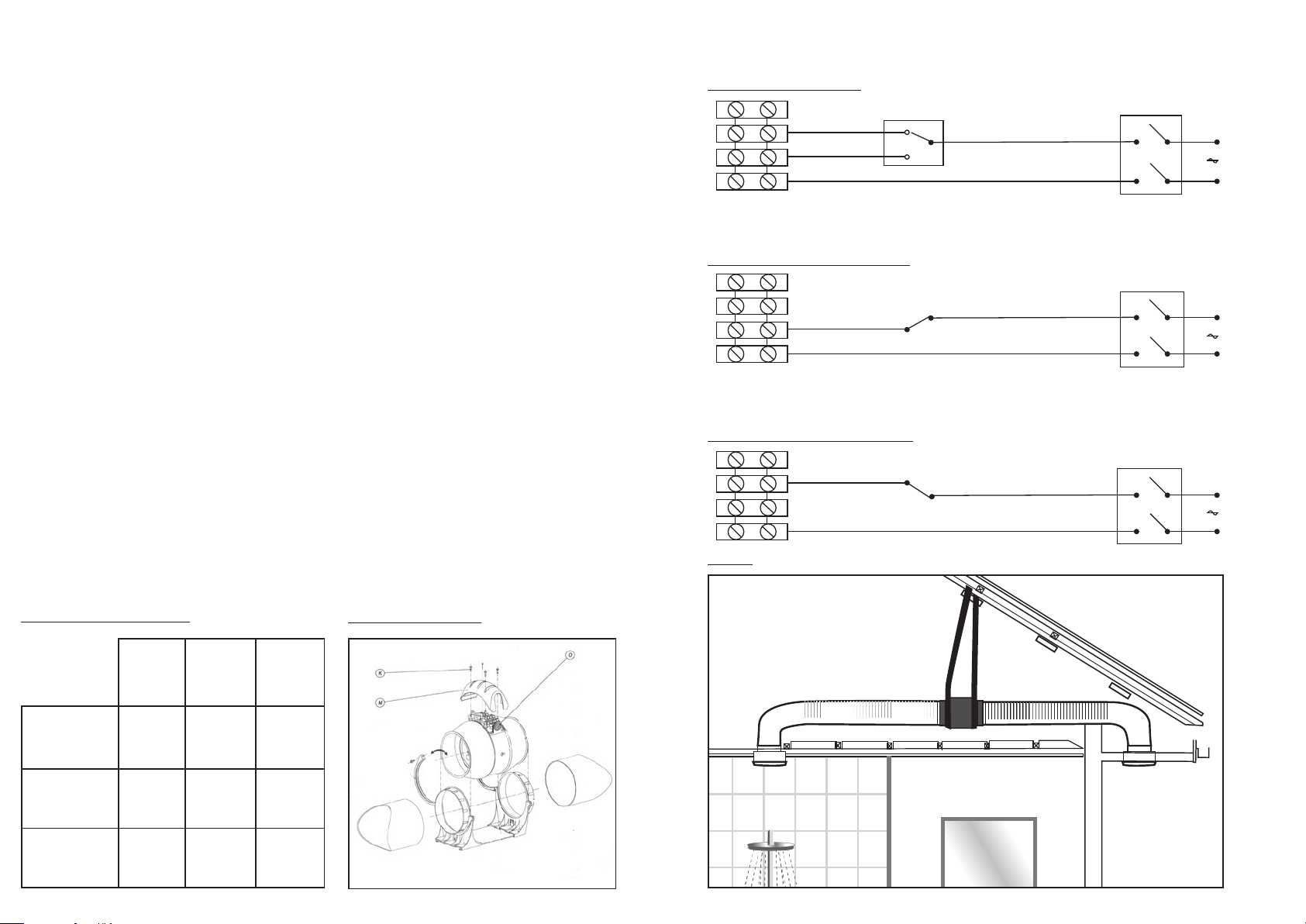
Wiring Diagrams below for the speed options:
Fig. 3: 2 Speed control
HS
LS
L
To make the electrical connections:
Loosen the 4 screws (K) and take off the connection cover (M) (Fig. 2).
Cut the electrical supply gromet (D) to allow the power supply wires to pass through.
Make the appropriate electrical connections as indicated in Figs. 3, 4 or 5:
• If you wish to install a switch to choose between high speed (HS) and
low speed (LS), see the wiring diagram in (Fig. 3).
• If you wish the fan to work only at low speed (LS), see the wiring diagram
in (Fig. 4).
• If you wish the fan to work at high speed (HS), see the wiring diagram in (Fig. 5).
ELECTRICAL CONNECTION
• The extractor fan must be connected to a single-phase mains network, with the
voltage and frequency indicated on the fan specication plate.
• The installation must have a switch with a distance between contacts equal to or
over 3mm.
• Earthing is not required as this fan has double insulation. (Class II).
• If the fan model you have purchased is not tted with a supply cord then please
note that is must be wired with a xed permanent connection.
Fig. 1:Hole cut out sizing
Fig. 2:Fan assembly
N L1 L2 T
Fig. 4: Low Speed control only
L2 T
LS
N L1
Fig. 5: High Speed control only
HS
N L1 L2 T
Fig. 6:
N
L
N
L
N
MFLP100
(FAN2049)
Interior Grille
(with gib clips)
Interior Grille
(without clips)
Exterior Grille 110mm 135mm 160mm
115mm 130mm 165mm
105mm 125mm 155mm
MFLP125
(FAN2050)
MFLP150
(FAN2051)
 Loading...