

SImx Mightylite LHT0237, Mightylite LHT0236 Installation Manual
CALIBRATION
This light fitting only operates when the PIR sensor is activated by heat movement within its detection zone.
Once power is connected, the unit requires approx. 60 sec to warmup. During this time the light will turn on
for approx. 5 sec then turn itself off. Do not commence any walk tests until this time has elapsed.
The TIME adjustment (marked “T”) has a minimum setting of approx. 15sec (counter clockwise rotation
to the end) which it should be set to for walk testing the unit. Adjust this setting clockwise to the preferred
duration the light activates for when it last detects movement. The maximum clockwise setting is approx. 5
mins. The timer will restart each time the sensor detects any new movement.
The LUX adjustment (marked “F”) sets the acceptable amount of light present before the unit will activate.
Rotating the dial to position “5” sets the light to activate during daylight and position “1” sets the light to
activate only at night. Set to desired activation point depending on the needs of the installation.
The RANGE adjustment (marked “R) alters the range of detection and the amount of infra-red radiation (heat)
required to trigger the sensor. To be effective but keep nuisance tripping to a minimum, it is advised to turn
the RANGE control to the middle position where the ambient temperature is between 15°-20°C. This range
sensitivity adjustment can also be used to compensate for the changes in outside air temperature in Winter
(set lower) and Summer (set higher).
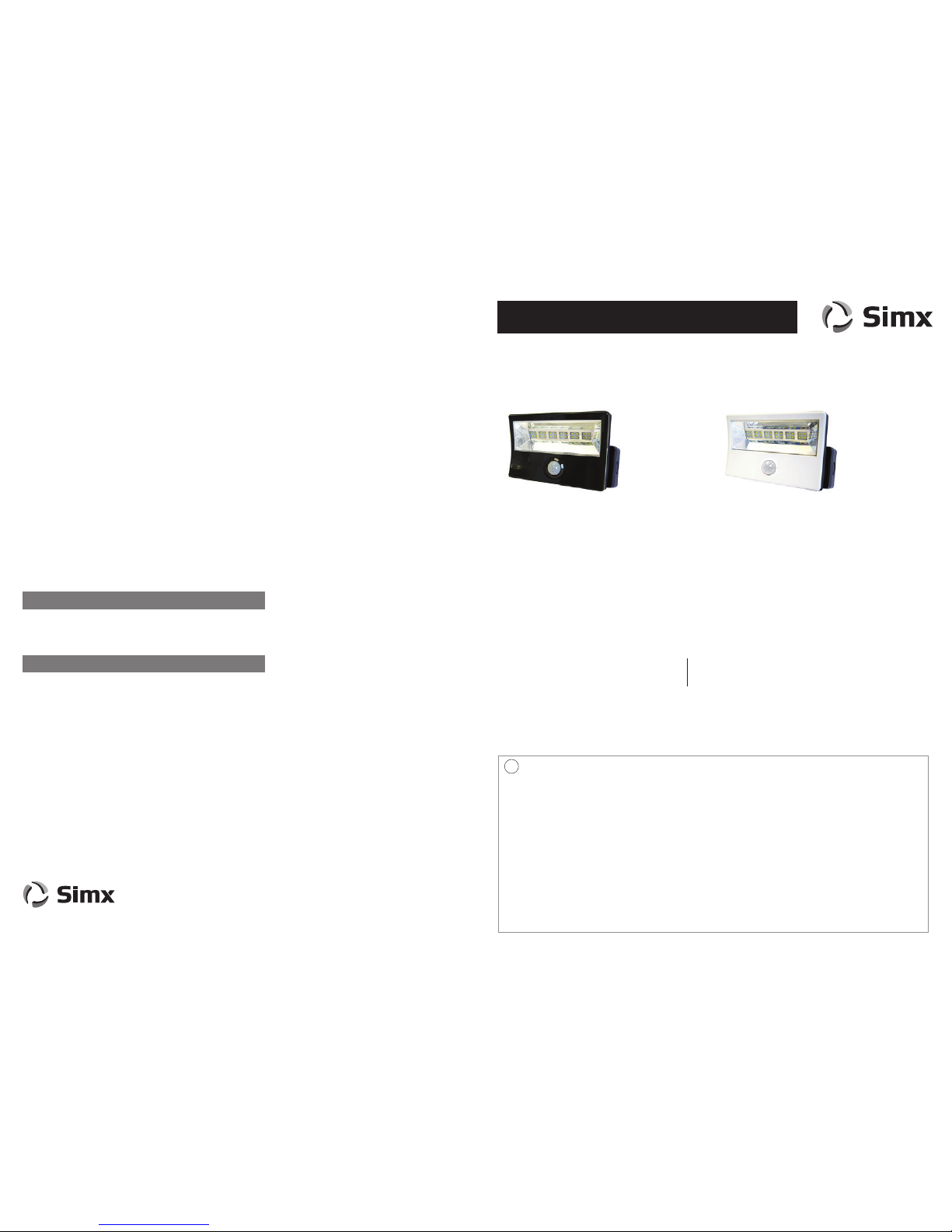
Model: Mightylite 15 Watt and 24 Watt PIR Floodlight
INSTALLATION INSTRUCTIONS
This product is suitable for use only with a supply voltage of 220-240V AC 50Hz.
All electrical work must be carried out in accordance with local and national electrical codes as applicable.
We strongly recommend that this light fitting is installed by a registered electrician.
Always switch power off prior to installation. A means of mains power isolation must be installed on the
circuit for the purpose of safe access for any internal cleaning, recalibration, or maintenance.
This light fitting is not intended for use by persons (including children) with reduced physical, sensory or
mental capabilities, or lack of experience and knowledge, unless they have been given supervision or
instruction concerning use of the appliance by a person responsible for their safety. Young children should
be supervised to ensure that they do not play with the appliance.
There are no user servicable parts in this light fitting.
Any changes or modifications made or attempted to this product, without the prior written approval of the
manufacturer, will void any and all stated warranties.
IMPORTANT
!
TECHNICAL SPECIFICATIONS
Thank you for purchasing this SIMX floodlight. This light is suitable for outdoor use and requires
a 220 – 240V AC power supply. Please read this manual thoroughly before use and retain for
future reference.
Voltage: 220 - 240V AC
Detection Range: 10 metres max
Detection Angle: 120°
Time Setting: min 15 sec max 5 min
Dusk Control: Day to Night (adjustable)
Rated Load: 15 Watts 24 Watts
Luminous Flux: 930 lumens 1530 lumens
Light Beam Angle: 75°V - 99° H 74°V - 93° H
Working Temperature: -30° to +50° C
Ingress Protection: IP65 with gland - IP44 with rear grommet*
Construction: Polycarbonate UV stabilised & Alloy
MIGHTYLITE 15W Black
PIR LED Floodlight: LHT0234
MIGHTYLITE 15W White
PIR LED Floodlight: LHT0235
MIGHTYLITE 24W Black
PIR LED Floodlight: LHT0236
MIGHTYLITE 24W White
PIR LED Floodlight: LHT0237
This product is guaranteed by SIMX Ltd for 5 years from the date of purchase against faulty materials or
workmanship which affects its designed ability to detect or switch. During this period if the product has a
defect of this nature it will be repaired or replaced free of charge by SIMX with the same item, or a similar
one of higher specification. ON CONDITION THAT:
The buyer returns it to the seller from whom it was bought, freight paid.
The product has been bought by the user. ie a receipt/sales invoice is produced as proof of purchase.
The product has not been misused or handled carelessly, installed in anyway contrary to the installation
instructions, used on a supply voltage other than that indicated in the product specifications, or installed in
any unusually exposed or harsh environmental conditions.
This guarantee excludes liability for discolouration of paint or plastic, or any user serviceable parts. It
does not confer any rights other than those expressly set out above and does not cover any claims for
consequential loss or damage.
Our Goods come with guarantees that cannot be excluded under the New Zealand Consumer Law. You
are entitled to a replacement or refund for a major failure and for compensation for any other reasonably
foreseeable loss or damage. You are also entitled to have the Goods repaired or replaced if the Goods fail
to be of acceptable quality and the failure does not amount to a major failure.
MANUFACTURERS EXTENDED WARRANTY
PRODUCT COMPLIANCES
AS/NZS60598.1:2003 AS/NZS60598.2.5:2002 EN55015:2006
EN61000.3.2:2006 EN61000.3.3:2008 EN61000.4 (various clauses)
IEC61347.1:2002 IEC61347.2.13 EN61547:2009
AIMING
To aim the Mightylite, simply hold the connection box firmly whilst pivoting the head of the floodlight to the
required location.
NOTE: That this LED light has very intensive light output, which if incorrectly used could cause
eye damage. Care and consideration should be taken when the unit is located close to property
boundaries, to avoid unnecessary spill light or glare to neighbours, and to avoid unwanted
activation of the PIR by passing pedestrians or vehicles.
Ph: +64 9 259 1660 | Technical Support Ph: +64 9 259 1662
Email: sales@simx.co.nz | www.simx.co.nz
Pub1245 iss02 08/14
Simx reserves the right to alter technical specications without prior warning
* See installation of connection box for details
CHOOSING A LOCATION
Mount the floodlight on a solid wall 3-5 metres above the ground. Avoid positioning the light near
heat sources, such as hot ventilator ducts, air conditioning units, exhaust outlets, street lighting or
traffic which may interfere with PIR operation.
Avoid pointing the sensor towards objects that may move in the wind such as trees or shrubs,
or at highly reflective surfaces. Do not install this light in any location where it is likely to be knocked
or hit, or in hot or humid conditions such as bathrooms, shower rooms, or saunas. Due to the
heat output from the lamp, this light should not be directed at a wall or object within 1 metre.
When positioning the light, note that the PIR sensor is more sensitive to a heat source moving
across its coverage area and less sensitive to a heat source that moves directly towards the PIR
sensor.
INSTALLING THE CONNECTION BOX
We strongly recommend a registered electrician installs this floodlight.
Warning: Isolate the power supply before installation
The unit requires connection to a mains electrical supply. It is recommended that the unit is
connected using a core round flexible cable of at least 0.75mm² gauge. This gauge will help to
ensure that IP ratings are maintained.
Position the unit on the wall and mark the desired position for the connection box. Can be
positioned in either landscape or portrait planes. Ensure that cabling can easily enter the connection
box through either the knock-out at the rear of the box, or through those on the sides.
Use the connection box fixing holes to mark the 4 drill holes required to secure the box to the wall
(and mark the cable outlet location if required). Drill the wall and screw the connection box on to the
wall using the screws and wall plugs provided.
NOTE: If feeding the power cable through the knockout at the rear of the box, this will
need to be removed, the sealing grommet fitted and the cable pushed through BEFORE
it is secured to the wall. Once the screws are fitted, the screw cover caps (supplied) must
be used to maintain IP rating. Using the rear sealing grommet correctly will provide an
IP44 rating.
If feeding the power cable through a knockout on the side of the connection box the sealing gland
(supplied) should be used. Once the sealing gland is fixed to the connection box the cable should
be secured in place by gently tightening the outside cap to ensure the cable is secured firmly and
no water can get through into the connection box. When correctly installed, this gland will provide
an IP65 rating.
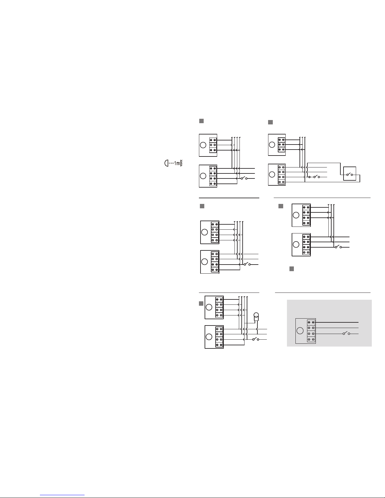
CONNECTING THE ELECTRICAL SUPPLY
There are several wiring configurations available for multiple unit installations of the Mightylite as
detailed in this manual. Up to 5 MightyLite PIR floodlights can be added to a Master unit. If more are
required a contactor or relay will be needed.
For standalone single unit installation, neutral, live and earth connections are used. The ‘Switch Live’
should not be used or linked in this instance as it may cause major failure to the product.
This is a Class I product requiring earth connections.
SWITCH LIVE
REPEAT UP TO MAX 5 UNITS
LIVE
OFF
ON
NEUTRAL
SWITCH LIVE
LIVE
NEUTRAL
WITH THE SWITCH LIVE NOT CONNECTED, EACH PIR AND LAMP TRIGGERS INDEPENDENTLY
LIVE
NEUTRAL
MIGHTY LITE PIR TERMINAL BLOCK
OFF
ON
LIVE
NEUTRAL
EARTH EARTH
MIGHTY LITE PIR TERMINAL BLOCK
EARTH
SWITCH LIVE
LIVE
NEUTRAL
SWITCH LIVE
LIVE
NEUTRAL
MIGHTY LITE PIR TERMINAL BLOCK
EARTH
MIGHTY LITE PIR TERMINAL BLOCK
EARTH
REPEAT UP TO MAX 5 UNITS
EARTH
SWITCH LIVE
LIVE
OFF
ON
NEUTRAL
LIVE
NEUTRAL
MIGHTY LITE PIR TERMINAL BLOCK
EARTH EARTH
1
<
3
5
2
4
Connecting Master (PIR) and
Slave (non PIR) Units on the
same circuit
Connecting Multiple Master
(PIR) Units for more flexible
perimeter solutions
Connecting Master (PIR) and
Slave (non PIR) Units with Manual
Override Function
NOTE: Above option could prevent another fitting
in close proximity from working due to the photcell
picking up the light from the illuminated unit and
the photocell may think it is daytime & not operate.
Successful operation will depend on the installed
spacing and aiming of each luminaire.
Once circuit wiring is completed, ensure the cover of the connection box has the gasket in place, then using
the screws provided secure the cover firmly to the connection box. We recommend the external screw cover
caps (supplied) be put in place, only after the electrical testing and calibration is completed.
SWITCH LIVE
REPEAT UP TO MAX 5 UNITS
LIVE
OFF
ON
NEUTRAL
SWITCH LIVE
LIVE
NEUTRAL
WITH THE SWITCH LIVE CONNECTED, WHEN ONE PIR TRIGGERS ALL LAMPS WILL ILLUMINATE
LIVE
NEUTRAL
MIGHTY LITE PIR TERMINAL BLOCK
SWITCH LIVE
REPEAT UP TO MAX 5 UNITS
LIVE
OFF
ON
NEUTRAL
SWITCH LIVE
LIVE
NEUTRAL
WITH THE SWITCH LIVE NOT CONNECTED, EACH PIR AND LAMP TRIGGERS INDEPENDENTLY
LIVE
NEUTRAL
MIGHTY LITE PIR TERMINAL BLOCK
OFF
ON
LIVE
NEUTRAL
EARTH EARTH
MIGHTY LITE PIR TERMINAL BLOCK
EARTH
EARTH EARTH
MIGHTY LITE PIR TERMINAL BLOCK
EARTH
SWITCH LIVE
LIVE
NEUTRAL
SWITCH LIVE
LIVE
NEUTRAL
MIGHTY LITE PIR TERMINAL BLOCK
EARTH
MIGHTY LITE PIR TERMINAL BLOCK
EARTH
REPEAT UP TO MAX 5 UNITS
EARTH
SWITCH LIVE
REPEAT UP TO MAX 5 UNITS
LIVE
OFF
ON
NEUTRAL
LIVE
NEUTRAL
LIVE
NEUTRAL
MIGHTY LITE PIR TERMINAL BLOCK
EARTH EARTH
MIGHTY LITE NON PIR TERMINAL BLOCK
EARTH
SWITCH LIVE
REPEAT UP TO MAX 5 UNITS
LIVE
OFF
ON
NEUTRAL
SWITCH LIVE
LIVE
NEUTRAL
LIVE
NEUTRAL
MIGHTY LITE PIR TERMINAL BLOCK
SWITCH LIVE
REPEAT UP TO MAX 5 UNITS
LIVE
OFF
ON
NEUTRAL
SWITCH LIVE
LIVE
NEUTRAL
LIVE
NEUTRAL
MIGHTY LITE PIR TERMINAL BLOCK
EARTH EARTH
MIGHTY LITE PIR TERMINAL BLOCK
EARTH
EARTH EARTH
MIGHTY LITE PIR TERMINAL BLOCK
EARTH
SWITCH LIVE
REPEAT UP TO MAX 5 UNITS
LIVE
OFF
ON
NEUTRAL
SWITCH LIVE
LIVE
NEUTRAL
WITH THE SWITCH LIVE CONNECTED, WHEN ONE PIR TRIGGERS ALL LAMPS WILL ILLUMINATE
LIVE
NEUTRAL
MIGHTY LITE PIR TERMINAL BLOCK
SWITCH LIVE
REPEAT UP TO MAX 5 UNITS
LIVE
OFF
ON
NEUTRAL
SWITCH LIVE
LIVE
NEUTRAL
WITH THE SWITCH LIVE NOT CONNECTED, EACH PIR AND LAMP TRIGGERS INDEPENDENTLY
LIVE
NEUTRAL
MIGHTY LITE PIR TERMINAL BLOCK
ONE MASTER ONE SLAVE WHEN THE PIR TRIGGERS ALL LAMPS WILL ILLUMINATE
OFF
ON
ADDING A REMOTE INDICATOR LIGHT OR BUZZER , WHICH WILL ACTIVATE WHEN A PIR IS TRIGGERED
LIVE
NEUTRAL
OFF
ON
LIVE
NEUTRAL
OFF
ON
MANUAL OVERRIDE SWITCH
EARTH EARTH
MIGHTY LITE PIR TERMINAL BLOCK
EARTH
EARTH EARTH
MIGHTY LITE PIR TERMINAL BLOCK
EARTH
SWITCH LIVE
LIVE
NEUTRAL
SWITCH LIVE
LIVE
NEUTRAL
MIGHTY LITE PIR TERMINAL BLOCK
EARTH
MIGHTY LITE PIR TERMINAL BLOCK
EARTH
REPEAT UP TO MAX 5 UNITS
EARTH
SWITCH LIVE
REPEAT UP TO MAX 5 UNITS
LIVE
OFF
ON
NEUTRAL
LIVE
NEUTRAL
LIVE
NEUTRAL
MIGHTY LITE PIR TERMINAL BLOCK
EARTH EARTH
MIGHTY LITE NON PIR TERMINAL BLOCK
EARTH
SWITCH LIVE
REPEAT UP TO MAX 5 UNITS
LIVE
NEUTRAL
LIVE
NEUTRAL
MIGHTY LITE PIR TERMINAL BLOCK
EARTH
MIGHTY LITE NON PIR TERMINAL BLOCK
EARTH
EARTH
SWITCH LIVE
REPEAT UP TO MAX 5 UNITS
LIVE
OFF
ON
NEUTRAL
SWITCH LIVE
LIVE
NEUTRAL
LIVE
NEUTRAL
MIGHTY LITE PIR TERMINAL BLOCK
EARTH EARTH
MIGHTY LITE PIR TERMINAL BLOCK
EARTH
ONE MASTER ONE SLAVE WHEN THE PIR TRIGGERS
ALL LAMPS WILL ILLUMINATE
WITH THE SWITCH LIVE CONNECTED, WHEN ONE
PIR TRIGGERS ALL LAMPS WILL ILLUMINATE
ADDING A REMOTE INDICATOR LIGHT OR BUZZER,
WHICH WILL ACTIVATE WHEN PIR IS TRIGGERED
WITH THE SWITCH LIVE NOT CONNECTED, EACH PIR AND LAMP
TRIGGERS INDEPENDANTLY
ONE MASTER, ONE SLAVE WHEN THE MANUAL OVERRIDE SWITCH IS ON, THE LAMPS REMAIN
ILLUMINATED CONTINUOUSLY UNTIL THE SWITCH IS SWITCHED OFF, THEN THE LIGHT WILL
REVERT TO NORMAL PIR DETECTION MODE.
Standalone Single Unit Installation
 Loading...