

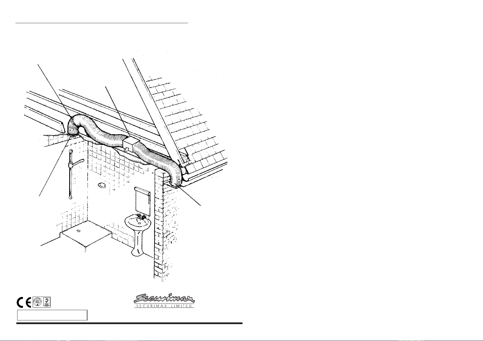
Example of a ID230 fan installation in a bathroom.
Flexible Ducting
Shower Fan
Internal
Grille
* We recommend hanging the fan
from a joist where possible.
*
External
Grille
INSTALLATION INSTRUCTIONS FOR
THE ID230 FAN.
NOTE:(i) Do not install the unit within a shower cubicle or anywhere
else where there is a high risk of the fan being sprayed with
water.
(ii) Switch off mains supply before making electrical connections
If in any doubt contact a qualified electrician.
(iii) This fan is double insulated and does not require an earth.
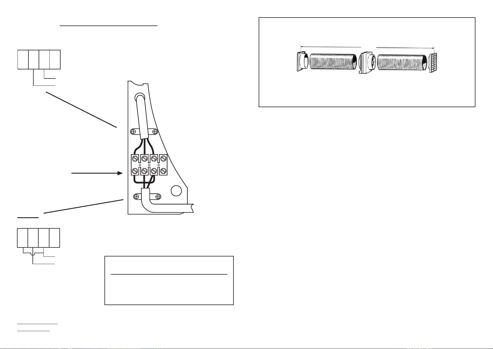
1. Fit suitable ducting flush to the plaster on grilles.
2. Remove the cover from the fan by removing the two small
screw caps on the front cover and remove the two retaining
Philips screws
3. Bring power cable into position, as marked. Allow an extra
350mm protruding to facilitate connection. Fan should only be
installed by fixed wiring, a flexible cord should not be used.
4. When installing the external grille first take the grille insert out
using a flat screwdriver and then drill 4 holes in the corners, mark
screw holes on the wall, and fix external grille.
IMPORTANT
• Isolate the main supply before making any electrical connections
This system should be installed by a qualified electrician.
• When fitting through an external wall, an external grille must be
fitted at all times.
• Fan should only be installed by fixed wiring, a flexible cord
should not be used.
• The appliance is not intended for use by young children or
infirm persons without supervision.
• Young children should be supervised to ensure that they do not
play with the appliance.
Manrose Manufacturing Ltd reserve the right
*
to change specification without prior warning
PUB0177 iss:03 10/08
Technical Support Telephone (09) 259 1662 Facsimile: (09) 259 1661
Email: sales@securimax.co.nz Website: www.securimax.co.nz
PO Box 14 347 Panmure, Auckland, NZ.
L1N
23L4
LIVE IN
NEUTRAL IN
12
EXTRACT ONLY
MODELS
XFS230/300 XPS230/300
XFS230P/300P XPS230P/300P
XFS230MP/300MP XPS230MP/300MP
L
L1N
2 3L4
LIVE IN
NEUTRAL IN
1 2
EXTRACT ONLY
MODELS
L
NUMBER
TERMINALS
LL N L
1 2
1 2 3 4
TYPICAL INTERNAL
WIRING LAYOUT
POWER
SUPPLY IN
WIRING DIAGRAM
up to 8m
IMPORTANT
All wiring must comply with current Regulations.
The fan should not be accessible to a person using either the shower or bath.
These fans are double insulated and do not require an earth.
All wiring must comply with current regulations.
When using 1348 or 1349 Controllers
Extraction of air: Live supply connected to terminal 3 (L1) as shown
Supply of air: Connect live to terminal 4 (L
If using Auto Shutter model fans with
these controllers the bridge wire must
be removed from terminals 1 & 3
2
) & move bridge wire from (1+3) to (1+4)
NOTE:
RATING / SPECIFICATIONS
For all electrical power and IP ratings refer to the fan rating and wiring label.
All fans are double insulated, manufactured to comply with
EN60335-2-80:1997 and are CE marked
Weight: 3.5kg
Electrical: 220-240V
Airflow: 550m
Max Temp: 40
3
/hr. 152l/s
o
C
Fan Wattage: 80W
IP Rating:
IP24
 Loading...