

2. Ducting
Put one end of the 150mm diameter duct into the vent hole and connect to
grill or cowl with one duct clip included . A 150mm diameter egg-crate grille
is included in the package to be used when installing in soffit. If installed
in wall a weatherproof cowl should be used. Seal grill/cowl with suitable
sealant.
Terminal
Blocks
Dear customers,
Please read all instructions before commencing installation.
MANROSE
Halogen Heater Fan & Light
INSTALLATION
A few minutes of planning can make a big difference to the installation
time and also to your satisfaction with the function of the unit.
1. Cutting a vent
Locate the exterior grill location on a wall or soffit, then cut a 155mm
diameter hole at this very position.
3. Suitable loacation
The heater must be installed at least 2.1m above the floor and no more
than 2.4m from the ground. The heater is most effective when you are
standing directly beneath it, so generally the unit would be mounted in a
place where you would stand to dry yourself. For the exhaust fan to work
efficiently, replacement air of a volume equivalent to what is being
Note: The length of each duct is 3.0m. Make sure that from the centre of
installation position there should be a distance within 3.0m to the outside
vent.
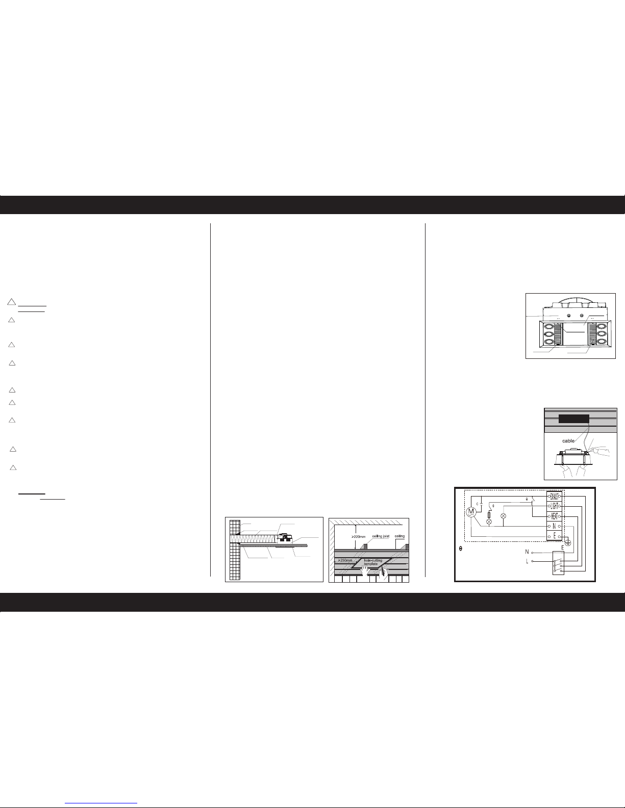
7. Wiring
Connect one end of the interconnecting
wire with the switch panel, and then
drag the other end power cable out of
the hole on the ceiling. Open the
terminal block cover on the housing and
make connection as the wiring diagram
instructs, then reposition the terminal
block cover. Tuck the excess wire into
the ceiling so as to leave the housing
enough room to fix in.
INSTALLATION INSTRUCTIONS AND HOLE-CUTTING TEMPLATE
Read and save these instructions! Please use this card as hole cutting template 450mm x 300mm.
Wall venting shown
wall
sealant
ventiduct
bathroom
heater
ceiling joist
ceiling
fascia
duct clip
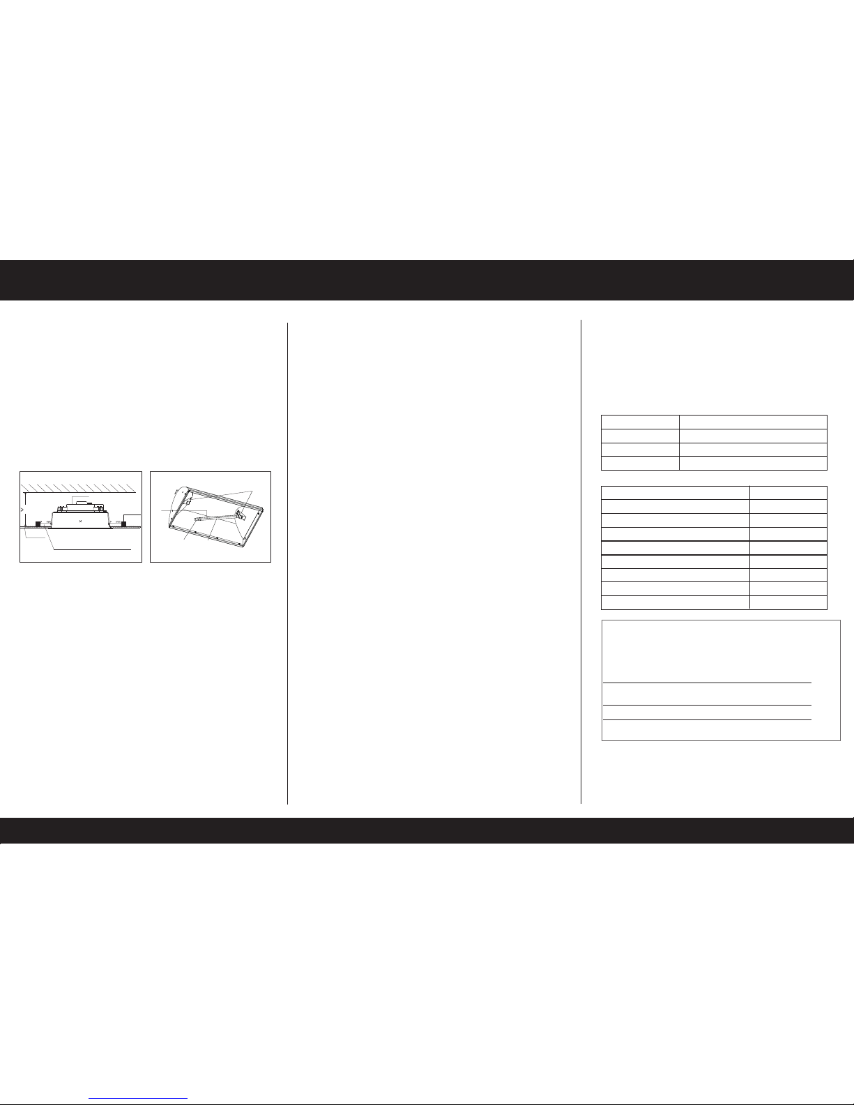
4. Prepare the ceiling
5. Remove the fascia
Remove 4 silicon clips at 2 ends of the rectangle air inlet grilles.
6. Remove the lamps
- Remove the 6 LED lamps from
the heater unit.
Heater Unit
Rubber clip
Air inlet grille
Glass shield
Screw behind rubber
Use this template to mark the hole outline on the ceiling. Make sure
a distance between the edges and wall is no less than 250mm. Also
from the rooftop should be a minimum 220mm height to the ceiling.
- Remove the halogen heat lamp
from the heater unit and keep it in
a safe place. Do not touch this
lamp with your bare skin.
Natural skin oils and salts damage new halogen lamps and
shorten their life. Only handle a new heat lamp with soft, dry, clean,
lint-free cloth or paper. You can wear gloves, cover your fingers or
wrap the heat lamp until it is installed (so long as you remove all cloth
or paper when finished).
• The power cable of this product must withstand a minimum 10A
load.
• The main supply and interconnecting cables required for installation
of this unit are not included.
• This unit must be properly grounded.
• The disconnection of the product is acheived by incorporating a
switch in the fixed wiring in accordance with the wiring rules. The
heater must be isolated from the power by means of a disconnection
switch with a contact separation of at least 3mm.
WARNING: Indicates that injury or death could occur if below
Warnings are not followed.
This unit must be installed to comply with the appropriate council
regulations and the Australia and New Zealand wiring rules
AS/NZS3000:2000 or lastest edition thereof.
All wiring must be carried out by a Licensed Electrician in accordance
with all applicable codes and standards.
Use this heater only as described in this manual. The manufacturer
does not recommend any other use as this may cause fire, electric
shock, or injury to persons. If you have questions, contact the
manufacturer or local agent.
Make sure the power is off before the installation.
The heaters glass shield is hot when in use. Do not touch the heat lamp
and glass shield with any part of your body when in use.
For the purpose of avoiding any dangerous gas leaking into your
bathroom, the duct vent of the heater must not be laid together with the
duct vent of air-fueled water heater or other open-fire appliances into
the same flue.
The heater is to be installed so that switches and other controls cannot
be touched by a person in the bath or shower.
This unit should not be installed directly above a shower or bathtub.
The unit must not be installed in a position where water may splash
onto the unit.
CAUTION: Possibility of damage to equipment, installation or premises
if below Cautions are not followed.
• The appliance is not intended for use by persons (including children)
with reduced physical, sensory or mental capabilities, or lack of
experience and knowledge, unless they have been given supervision or
instruction concerning use of the appliance by a person responsible for
their safety.
• Children should be supervised to ensure that they do not play with the
appliance.
• The appliance shall, under no circumstances, be covered with insulating
material or similar material.
• Regulations concerning the discharge of air have to be fulfilled.
• The unit must not be installed beneath a fixed socket.
• The unit is designed for installation in flat ceilings only. Do not mount it
on a sloping ceiling or a vertical wall.
• Before commencing any cutting, check in the ceiling space that there are
no obstructions such as electrical wiring, hidden utilities or ceiling joists
and that there is sufficient height clearance for the housing. Check that
the electrical wiring can be routed from the wall switches to the mounting
location.
• Joists, beams and rafters shall not be cut or notched to install the
appliance.
!
!
!
!
!
!
!
!
!
extracted must be able to enter the room. Generally, this air would be
drawn under the door with a minimum space of 20mm. If the room is
airtight, the fan will function poorly.
1
2
IR
LED
Thermal Protector
M:Motor
C:Capacitor
LED: Lamp
IR: Halogen
Remove the screws hidden
inside. Remove the fascia.
Note: Be careful while removing
the screws so that the fascia
does not drop to the ground.
This warranty does not cover damages or loss caused by:
1) Heat or light lamps.
2) Any consequential losses arising from incorrect installation or
operation or maintenance of this product.
3) Any consequential losses arising from incorrect wiring of this
product.
4) Any modifications or changes made to the unit, other than those
recommended by the Manufacturer.
MAIN TECHNICAL PARAMETERS
LIST OF PARTS
Operation unit
1000W Halogen Heat Lamp (LHT0326)
Manrose 4.5W GU-10 LED Lamp (LHT0211)
Installation instruction & hole-cutting template
1 piece
1 piece
6 pieces
1 piece
Backdraft stopper 1 set
Duct clip
Switch 1 piece
Warranty card
1 piece
3 pieces
Ducting kit 1 set
We reserve the rights to revise this instruction without any prior notice.
Model Number
Rated Voltage
Rated Frequency
Rated Power
230V-240V
50Hz
1100W
FAN5876
WARRANTY
The unit is warranted against defects in manufacturing and workmanship
for a period of 5 years. The warranty does not extend to lamp globes
supplied or installation of the unit or any associated wiring or any
damage caused by installation or wiring.
2. Lamp Replacement
- Shut off power before replacement.
- Use ONLY Manrose 4.5W GU10 LED Lamp for lighting - LHT0211
- Use ONLY 1000W Halogen Heat Lamp for heating - LHT0326
Note: Only use Manrose replacement bulbs as listed. Using other bulbs
may damage the unit.
MAINTENANCE
1. Clean
- Shut off the power before cleaning.
- Wipe the glass shield and fascia with care using a soft cloth soaked with
a neutral detergent. Check the glass shield is not loose from the slots
regularly.
Note: Ensure the lamps are cool enough to touch before handling.
Do not switch on/off frequently when in use. Shut off the power if in long
periods of inactivity.
2. Exhaust
‘FAN’ switch On/Off
This unit can exhaust odours and steam in a quick and efficient way by
turning on the “FAN” switch.
10. Final installation
- Install the heat lamp.
- Fit one end of the heat lamp into socket and gently push it away from
the other socket. When there is enough room, fit the other end of the
heat lamp into its socket (The heat lamp is half coated with a white
reflector. When you grasp the heat lamp with cloth or paper, face the
back of the reflector to the ceiling so you can see the heat lamp’s
filament. Not doing this will reduce performance)
- Reinsert the LED lamps.
- Check the glass shield to make sure that it is not damaged and is well
fixed on the fascia by the screws (A little movement of the glass won’t
cause any problem to the use)
- Replace the fascia with screws. Use 4 silicon clips to cover the
screws.
- Fix the switch panel to the wall.
Note: The switch wiring should be mounted inside the wall to give the
switch an integrated built in appearance. If it is necessary to run the
wiring on the outside of the wall, use a suitable conduit and fixings to
properly located and hold the wiring used.
8. Fit the in-house end of the duct to the fan outlet, and fix the end
with duct clip.
A backdraft stopper is included in the package, fit the stopper to the fan
outlet and fix it with one duct clip. Fit the in-house end of the duct to the
stopper, and fix the end with another duct clip.
Note: Keep the route as straight as possible.
USE
Our bathroom heater uses the halogen heating lamp (re-order code
LHT0326) as a source of heat. It also combines the functions of exhaust
and light.
1. Heat
‘HEAT’ switch On/Off
Do not touch the halogen heating lamp and the glass shield with any part
of your body when in use.
3. Lighting
‘Light’ switch On/Off
INSTALLATION INSTRUCTIONS AND HOLE-CUTTING TEMPLATE
Read and save these instructions! Please use this card as hole cutting template 450mm x 300mm.
bathroom heater
ceiling
ceiling joist
100
100
220mm
100mm minimum clearance
is required near all ceiling joists
Socket
Heat Lamp
Reflector
0
0
0
0
0
0
0
0
0
0
Filament
9. Position the housing into the hole
Choosing the best direction to put the housing into the hole in
accordance with the position of the fan outlet. Use screws to fix the unit
onto supports (not supplied). Ensure that the unit is held securely on
all 4 sides. You may have to add supports on 2 sides in between joists
or even build a frame to secure it properly into the ceiling with supports.
Note: Try to keep the excess wire away from the housing.
PLEASE NOTE:
The Manrose Halogen Heater Fan Light has a Triple Thermal Protection
System: The Heater FL is equipped with automatic resettable thermal
switches. If the Heater FL overheats, the unit will shut off automatically.
The unit will operate normally after cooled.
The installation must be conducted by a licensed electrician and a
suitable certificate of safety is to be issued by the electrician who
installed the unit. Warranty claims will be voided unless a certificate of
safety can be produced when required, prior to service or repair.
For warranty purposes fill out the following details and save with proof of purchase.
This infortmation must be submitted in the unlikely event that this product fails.*
MODEL NO.:
FAN5876
Purchased from:
Date of purchase:
*All warranty claims must be submitted through returns@simx.co.nz
 Loading...