

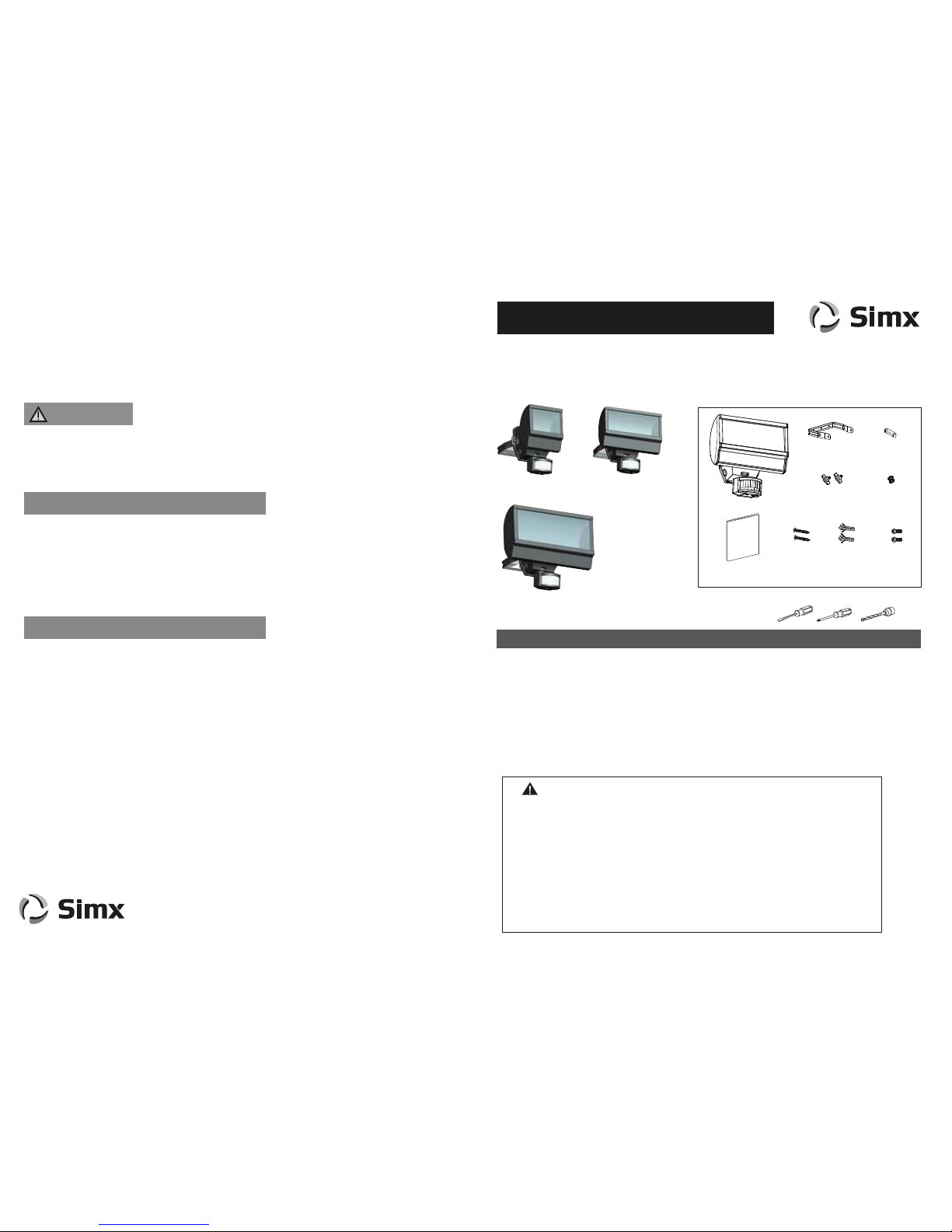
INSTALLATION INSTRUCTIONS
Contents:
INSTRUCTIONS
MANUAL
X 1
X 1 X 2 X 2
Screw:
M4x32mm
Screw peg:
6x30mm
X 2
Screw:
M3x12mm
X 1
X 2 X 2
Hand screw Star washer
TECHNICAL SPECIFICATIONS
This product is suitable for use only with a supply voltage of 220-240V AC 50Hz.
All electrical work must be carried out in accordance with local and national electrical codes as
applicable. We strongly recommend that this light fitting is installed by a registered electrician.
Always switch power off prior to installation. A means of mains power isolation must be installed on the
circuit for the purpose of safe access for any internal cleaning, recalibration, or maintenance.
This light fitting is not intended for use by persons (including children) with reduced physical, sensory
or mental capabilities, or lack of experience and knowledge, unless they have been given supervision
or instruction concerning use of the appliance by a person responsible for their safety. Young children
should be supervised to ensure that they do not play with the appliance.
Any changes or modifications made or attempted to this product, without the prior written approval of
the manufacturer, will void any and all stated warranties.
IMPORTANT
X 1
Manual
U bracket Cable clamp
Tools required:
Tools / Equipment need for installation.
MODEL: LHT0277, LHT0278, LHT0279, LHT0280, LHT0281 and LHT0282
PRODUCT COMPLIANCE
MANUFACTURERS EXTENDED WARRANTY
Manual Override Mode
LHT0277
LHT0278
12W
Black
White
LHT0279
LHT0280
20W
Black
White
LHT0281
LHT0282
26W
Black
White
PIR Operation: Auto / Manual / D-MODE
PIR Detection Range: up to 10 metres
PIR Detection Angle: 120º at 3m; 80º at 10 metres
PIR Time Setting: min 3 - 10 secs
max 9 - 11 mins
PIR Dusk Control: Day to night (adjustable)
PIR Aiming Adjustment: Pan left 90º and right 90º
Tilt down 50º
Construction: Alloy Housing,
Stainless Steel 304 Bracket + Screws,
UV Stabilised Polycarbonate
Supply Voltage: 220 - 240V AC 50Hz
Power Factor: >0.92
Stand By Load: 0.5W max
Working Temperature: -20°C to +40°C
Ingress Protection: IP55
Protection Class: Class II
Light Beam Angle: 110º
Lamp Data: 5700k, CRI >80
Luminous Flux:
12W 20W 26W
500lm 1000lm 1500lm
Distributed by: Simx Limited
Ph: +64 9 259 1660 | Technical Support Ph: +64 9 259 1662
Email: sales@simx.co.nz | www.simx.co.nz
Simx reserves the right to alter technical specifications with prior warning
PUB1301 iss01
This product is guaranteed by SIMX Ltd for 36 MONTHS from the date of purchase against faulty materials or workmanship
which affects its designed ability to operate. During this period if the product has a defect of this nature it will be repaired
or replaced free of charge by SIMX with the same item, or a similar item, or a similar one of higher specification.
ON CONDITION THAT:
The buyer returns it to the seller from whom it was bought, freight paid.
The product has been bought by the user i.e. a receipt/sales invoice is produced as proof of purchase.
The product has not been misused or handled carelessly, installed in anyway contrary to the installation instructions, or
installed in any unusually exposed or harsh environmental conditions.
This guarantee excludes liability for discolouration of paint or plastic, or any user replaceable parts.
It does not confer any rights other than those expressly set out above and does not cover any claims for consequential loss
or damage.
Our Goods come with guarantees that cannot be excluded under the Australian and New Zealand Consumer law. You are
entitled to a replacement or refund for a major failure and for compensation for any other reasonably foreseeable loss or
damage. You are also entitled to have the Goods repaired or replaced if the Goods fail to be of acceptable quality and the
failure does not amount to a major failure.
This product will get warm when in normal use. It can be installed on surfaces of normal flammability e.g.
wood, plasterboard, brickwork and other masonry.
Do not install on flammable surfaces such as plastics.
Thank you for purchasing this SIMX Reflect LED PIR Floodlight. This light is suitable for outdoor use
and requires a 220 - 240 V AC power supply. Please read this manual thoroughly before installation
and retain for future reference.
Product complies with:
EN55015:2006/A1:2007 EN61000-3-2:2006 EN61003-3:2008 EN 61547:1995/A1:2000
IEC 61000-4-2:2008 IEC 61000-4-3:2006/A1:2007 IEC 61000-4-4:2004 IEC 61000-4-5:2005
IEC 61000-4-6:2008 IEC 61000-4-8:1993/A1:2000 IEC 61000-4-11:2004 EN 60598-1:2008
EN60598-2-5:1989 EN61347-2-13:2006 AS/NZ 60598-2-1 EN62493:2010 EN62031
IEC/EN 62471 IEC/TR62471-2 and relevant amendments.
The light can be switched on for longer time periods by use of the Manual Override Mode. To activate Manual
Override for continous light at night switch the internal wall switch/circuit breaker (OFF/ON) within 2 seconds.
The unit will now illuminate continuously until dawn or until it is switched back into Automatic Mode.
To cancel Manual Override Mode and switch the unit back into Automatic Mode, flick the internal wall
switch/circuit breaker (OFF/ON) within 1 second. The unit will return to normal motion sensor operation.
The light will flash on once to confirm activation and cancellation of this mode.
WARNING
LIVE
NEUTRAL
BLUE
BROWN
Detection Range:
Tilt down 50º
Pan left 90º
Pan right 90º
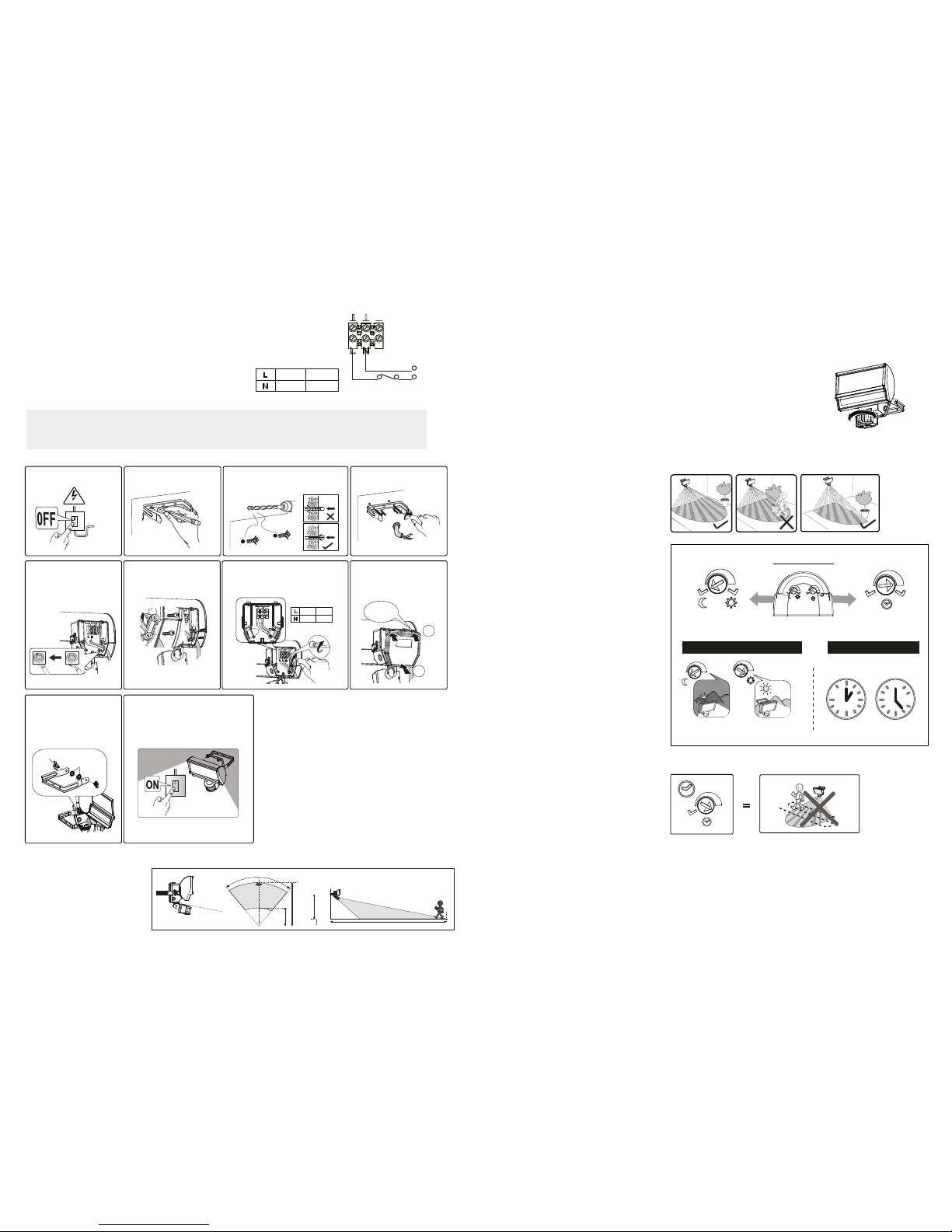
Motion Detector Head Aiming
The detector head can be 90º turned left or right by hand, it can be tilted 50º downward.
Do not use the adjuster knobs to turn the detector head.
Note: Make sure sensor head is positioned with control knob facing towards the
ground to maintain IP rating.
Walk Test and Adjustment
• Adjust the Time knob to lowest setting, (Lux knob can be “Sun” or Moon”).
• Switch power on.
• Walk across the detection area, once the detector is triggered the lamp will turn ON for 2 seconds.
• Aim sensor to adjust detection coverage.
Knob Settings
LED floodlight has two adjustment knobs:
Lux and Time at the bottom of the detector head.
• Adjust knobs carefully with flat blade screwdriver.
TIME knob setting
• You can set the time knob from 10 sec to
about 10 min, LED flood light will turn ON the
lamp, for the time duration set after each
detection movement.
• Setting time knob to D will activate D-MODE.
LUX knob setting
• When setting the LUX knob at “MOON” PIR
activation will only operate in the dark.
• When setting the LUX knob at “SUN”, PIR
activation wll operate in any light level.
D-MODE Dusk to Dawn
• When setting the TIME knob to fully clock
wise ‘D’ setting, the motion detector of the
LED floodlight will not function.The lamp will
then operate depending on the “LUX” level.
• Set to “Moon”, lamp will illuminate from Dusk
to Dawn.
• Set to “Sun”, lamp will illuminate all day and
all night. The light will flash 3 times to confirm
D-MODE activation and deactivation.
D
10min10sec
0
Min
10
10
sec
Turn On time adjustment
Environment lux level to turn On
Lamp turns
ON at night.
Lamp turns ON
at day & night.
Adjustments
Lux
Time
D
Auto Mode
ASSEMBLY AND INSTALLATION INSTUCTIONS
N
L
Isolation Switch
*** IMPORTANT ***
Isolate electrical supply before proceeding with the installation.
This light fitting should be installed by a registered electrician.
Recommended installation height
is 2.5 meter above ground, the
maximum detection range about
10 metre and at the angle of
about 80 degrees.
Installation Procedure:
80º
3m
10m
2.5m
10m
This light fitting is rated to IP55. This means that it is suitable for use in exterior
locations. Please ensure the desired location does not exceed this rating.
Connect the cable to the terminal block as follows
(see connection diagram).
Ensure the connections are secure.
Connection
230V
1. Switch off the power.
5. Feed the power cable
through the rubber gasket of
the junction box. Pierce the
gasket, do not cut or slice it.
Star washer
Hand screw
9. Attach the device to the
U bracket with star washers,
aim then tighten the screws
on both sides.
10. Connect device to the mains.
Unit goes into warm-up period for
35-45secs.
6. Attach the strain relief
to the device and tighten
screws firmly.
LIVE
NEUTRAL
BLUE
BROWN
7. Connect the individual wires to
the appropriate terminal then
tighten the screw.
Push
1
2
“Click”
8. Attach the rear cover to
the device. Ensuring it clicks
firmly into place.
2. Marking the
screw hole.
4. Fix the U bracket to
the wall.
φ
6mm
3. Drill and push the screw
peg into the hole.
PIR Lens Masking
The purpose of the lens mask is to block out
areas not desired for detection. Apply to PIR
lens as required for your location.
Mounting Srews:
(M4 x 32mm) x 2
Mounting Srews:
(M3 x 12mm) x 2
 Loading...