

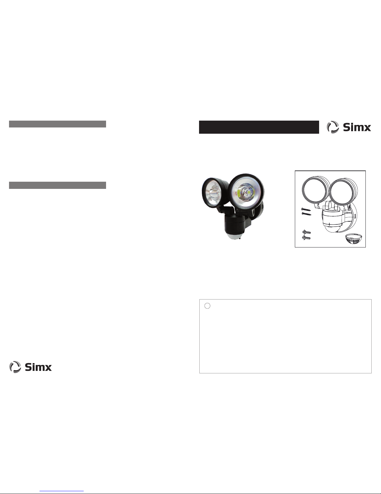
Model: 2 x 4 Watt Sensor LED II
INSTALLATION INSTRUCTIONS
This product is suitable for use only with a supply voltage of 220-240V AC 50Hz.
All electrical work must be carried out in accordance with local and national electrical codes as applicable.
We strongly recommend that this light tting is installed by a registered electrician.
Always switch power o prior to installation. A means of mains power isolation must be installed on the circuit
for the purpose of safe access for any internal cleaning, recalibration, or maintenance.
This light tting is not intended for use by persons (including children) with reduced physical, sensory
or mental capabilities, or lack of experience and knowledge, unless they have been given supervision or
instruction concerning use of the appliance by a person responsible for their safety. Young children should be
supervised to ensure that they do not play with the appliance.
Any changes or modications made or attempted to this product, without the prior written approval of the
manufacturer, will void any and all stated warranties.
IMPORTANT
!
TECHNICAL SPECIFICATIONS
Distributed by: Simx Limited
Ph: +64 9 259 1660 | Technical Support Ph: +64 9 259 1662
Email: sales@simx.co.nz | www.simx.co.nz
Simx reserves the right to alter technical specications without prior warning
Detection range: 8 ± 2 m
Detection Angle: 140° at 3 metres; 90° at 8 metres
Time setting: min 30 sec ± 10 sec
max 6 min ± 2 min
Dusk control: Day to night (adjustable)
PIR Aiming adjustment: Pan only, left 90° & right 90°
Rated load: 9W max
Luminous flux: 220 lumens per lamp
Light beam angle: 30° to 1/2 peak intensity
Working temperature: -20° C ~ +40° C
Ingress Protection: IP44
Construction: Polycarbonate UV stabilised
This product is guaranteed by SIMX Ltd for 36 MONTHS from the date of purchase against faulty materials
or workmanship which aects its designed ability to detect or switch. During this period if the product has a
defect of this nature it will be repaired or replaced free of charge by SIMX with the same item, or a similar one
of higher specication. ON CONDITION THAT:
The buyer returns it to the seller from whom it was bought, freight paid.
The product has been bought by the user i.e. a receipt/sales invoice is produced as proof of purchase.
The product has not been misused or handled carelessly, installed in anyway contrary to the installation instructions, or
installed in any unusually exposed or harsh environmental conditions.
This guarantee excludes liability for discolouration of paint or plastic, or any user replaceable parts. It does not confer
any rights other than those expressly set out above and does not cover any claims for consequential loss or damage.
Our Goods come with guarantees that cannot be excluded under the Australian and New Zealand Consumer Law.
You are entitled to a replacement or refund for a major failure and for compensation for any other reasonably foreseeable
loss or damage. You are also entitled to have the Goods repaired or replaced if the Goods fail to be of acceptable quality
and the failure does not amount to a major failure.
MANUFACTURERS EXTENDED WARRANTY
PRODUCT COMPLIANCES
Thank you for purchasing this SIMX sensor light. This light is suitable for both ceiling or wall
installation and sheltered outdoors. It requires a 220 ˜ 240V AC power supply. Please read
this manual thoroughly before installation and retain for future reference.
Product complies with:
AS/NZS60598.1:2003 AS/NZS60598.2.5
EN55015:2006 EN61000.3.2:2000 EN61000.3.3:1995 EN61547:1995
EN62031 EN 62471:2008 EN62471 EN60529 and relevant amendments.
2x
4x 32 mm
6x 30 mm
2x
1x
LHT0267 Black
LHT0268 White
PUB1322 iss01
This light tting only operates when the PIR sensor is activated by heat movement within its detection zone. Once power is
connected, the unit requires approx. 60 seconds to warm up.
Do not commence any walk tests until this has occurred.
CALIBRATION
The TIME adjustment has a minimum of approx. 30 seconds (counter clockwise rotation to the end) which it should be set to
for walk testing the unit (Fig D). Adjust this setting clockwise to the preferred duration the light is activated for when it detects
movement. The maximum clockwise setting will be approx. 6 minutes. The timer will restart each time the sensor detects any
new movement.
The LUX adjustment sets the acceptable amount of light present before the unit will start detecting. Rotating the dial clockwise
to the end will set it to full daylight operation. Use this setting for walk testing the unit (Fig D). Fully rotating counter clockwise
will set the unit to activate after dark only.
The PIR sensor has a 140° detection angle. This detection angle can also be aimed 90° left or right by pivoting the PIR cover
where it joins the main housing.
The lens mask supplied can be used when needed for restricting detection angles of the PIR (Fig E). Removing the largest
centre segment provides a 40° detection area, while removing all segments provides maximum 140° angle. The mask clips
into place. Remove one segment at a time, aim, and check in walk test mode. Continue removing segments until correct
coverage is achieved.
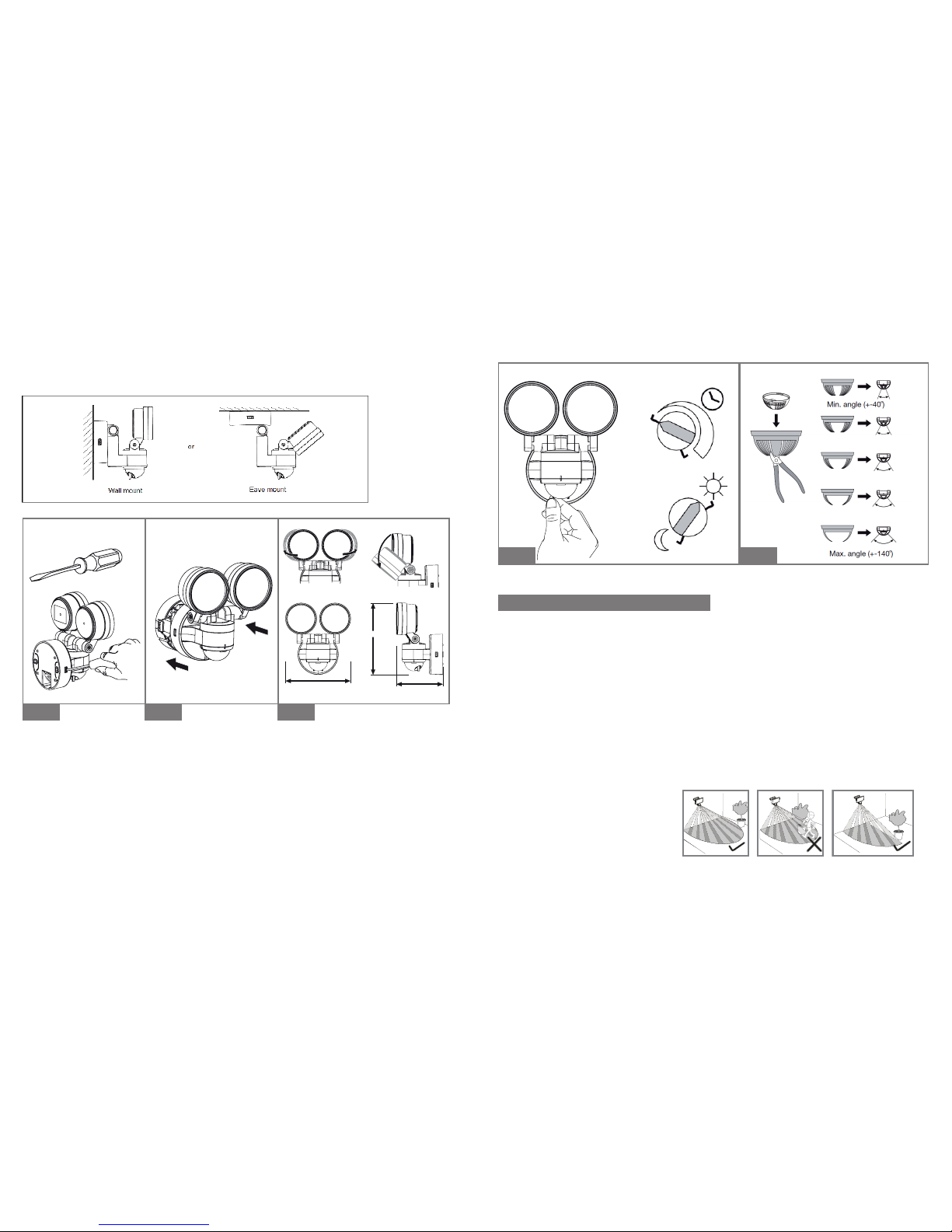
Time/Sensitivity Adjustment
INSTALLING YOUR SENSOR LED II LIGHT
This light tting is rated to IP44. This means that it is suitable in areas which may receive light rainfall. Please ensure the
desired location does not exceed this rating.
Switch off the power supply before commencing electrical work.
Using a at head screwdriver, carefully lever the side tabs to separate the mounting base from the
main housing (Fig A).
Pierce the power entry grommet on the mounting base and slowly draw a round mains power
cable through the power entry hole. Recommended use of 1.5mm2 - 2.5mm2 wire
for installation.
Firmly secure the base to the wall or ceiling using the mounting screws provided. Mounting holes
located in the base are at 60mm centres.
Wire the cable to the terminal block, ensuring accurate polarity. Failure to do this correctly will result
in irreparable lamp and sensor failure. A terminal for Earth parking is provided if required. Locate the
main housing over the base and push together until it ‘clicks’ into nished position (Fig B).
Adjust the base pivot to orientate the tting with the sensor adjustors pointing downwards.
Tighten thumb screw to secure. Aim spotlight head to suit the locations.
Fig D Fig E
Minimum On Time
setting
Maximum LUX
setting
Fig A Fig B Fig C
“click”
“click”
(60˚ left & right-
2 spot pan together)
124mm
135mm
88mm
30˚ 30˚
50˚
PIR LENS MASKING
The purpose of the lens mask is to block out
areas not desired for detection. Apply to PIR
lens as required for your location.
Care and consideration should be taken when the unit is located close to property boundaries, to avoid unnecessary spill
light or glare to neighbours, and to avoid unwanted activation by passing pedestrians or vehicles.
Special Note
SUPERIOR ADJUSTMENT VERSATILITY
Dual Mounting Options
 Loading...