

Page 1
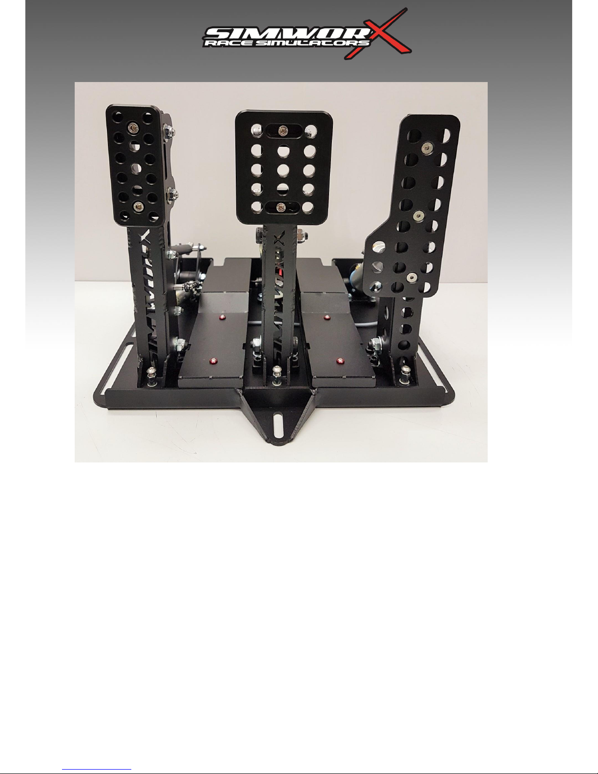
Pro Series V3 LC GT Pedal Set
USER MANUAL
Load Cell Spec
Page 2

Thank you for purchasing our Pro GT V3 Pedal Set. We are sure you will enjoy your purchase.
The Pro Series range of controls are products that were designed and developed by SimworX with the ultimate aim of
supplying the most realistic motorsport inspired controls for the ultimate virtual racing experience. Each product is
pre-tested prior to shipping to ensure your investment is ready to go once you’ve received it. We continually upgrade
our controls to ensure the pedals are robust and give positive feel and feedback. A 12 bit resolution USB interface
ensures accurate pedal control whilst the unique Hydraulically loaded Load Cell activation system enables the braking
system to be fully tuned in to your racing style.
A load cell works the way it feels. It is measuring force (same as a brake) and feels like a brake because it gets
harder to get it to "max" due to the progressive resistance that gets harder and harder. The perfect pedal for sim
racing is to have hydraulics in the system because that's what real brakes are, and in conjunction with the load cell,
the force outputs to a 12 bit resolution circuit board for accuracy. Simworx has also introduced a rocker arm that the
load cell cylinder system pressures up, and by introducing variable durometer dampers that works against the rocker
arm’s action, a very finely tuned end stop feel can easily be attained. In a good race pedal system, the pedal barely
moves once the pads touch the rotor. A good racecar brake pedal feels like stepping on a brick once full pad pressure
has been attained and that is achievable with this system. If that’s not to your liking, you can back it off by using the
thumb screw and/or interchanging the supplied dampers. Brake feel is very subjective, that’s why all of these
adjustments have been introduced.
The following instructions will guide you through the installation process and the various adjustability options
built into the unit
1x Pro GT Pedal Set
1x Pro GT Heel Plate
1x 3M USB Cable
2 x Urethane Load Cell Rocker Arm Bushes
1x Stainless Steel Bolt Pack with Alloy Washers
1 x Allen Key Set
1x User Manual
For owners of existing Simworx SX02 series simulators and/or chassis units, the mounting points for the pedals and
heel plates are already in place. Locate the pedals and with the supplied bolt set insert them in to the pre-tapped bolt
holes. Slot the heel plate over the front edge of the pedal base and lock it in place with the supplied 6mm stainless
steel bolts.
For fitting to other simulators, make sure the frame is strong enough to withstand the forces you can exert on the
brake pedal. On the next page you will find a drilling guide for your Pedals & optional heel plate. Position the pedal
set & heel plate at your preferred location and using the slots either side of the base plate, carefully mark the hole
position through the pedal base slots onto your mounting surface.
Once you are satisfied with its location, drill a small pilot hole at each bolt location. Finish the holes for the pedal
set at 8.0 – 8.5mm & 6.0 – 6.5mm for the heel plate.
Bolt the pedal set in place using the supplied bolts and alloy cup washers in the bolt pack. Fasten the slot bolts first
and adjust the pedal position incrementally until you are satisfied with its final position. Once satisfied mark through
the two bolt holes either side of the brake pedal pivot mount , take the pedal set off again and drill the final two 8mm
holes where you marked them.
For final permanent mounting, bolt the two centre brake pivot holes first, then screw in the four slot bolts and
tighten securely. Please make sure they are secured tightly to ensure that the pedal set doesn’t flex under the
pressure. The mounting surface needs to be strong enough to withstand the 120kgs+ of pressure that can be exerted
on the brake pedal.
Finally, fit the optional heel plate if your rig allows it, it slots over the front edge of the pedal set base and is
bolted in place with two 6mm Stainless Steel screws and the countersunk alloy washers.
INTRODUCTION
PACKAGE CONTENTS
FITTING
Page 3
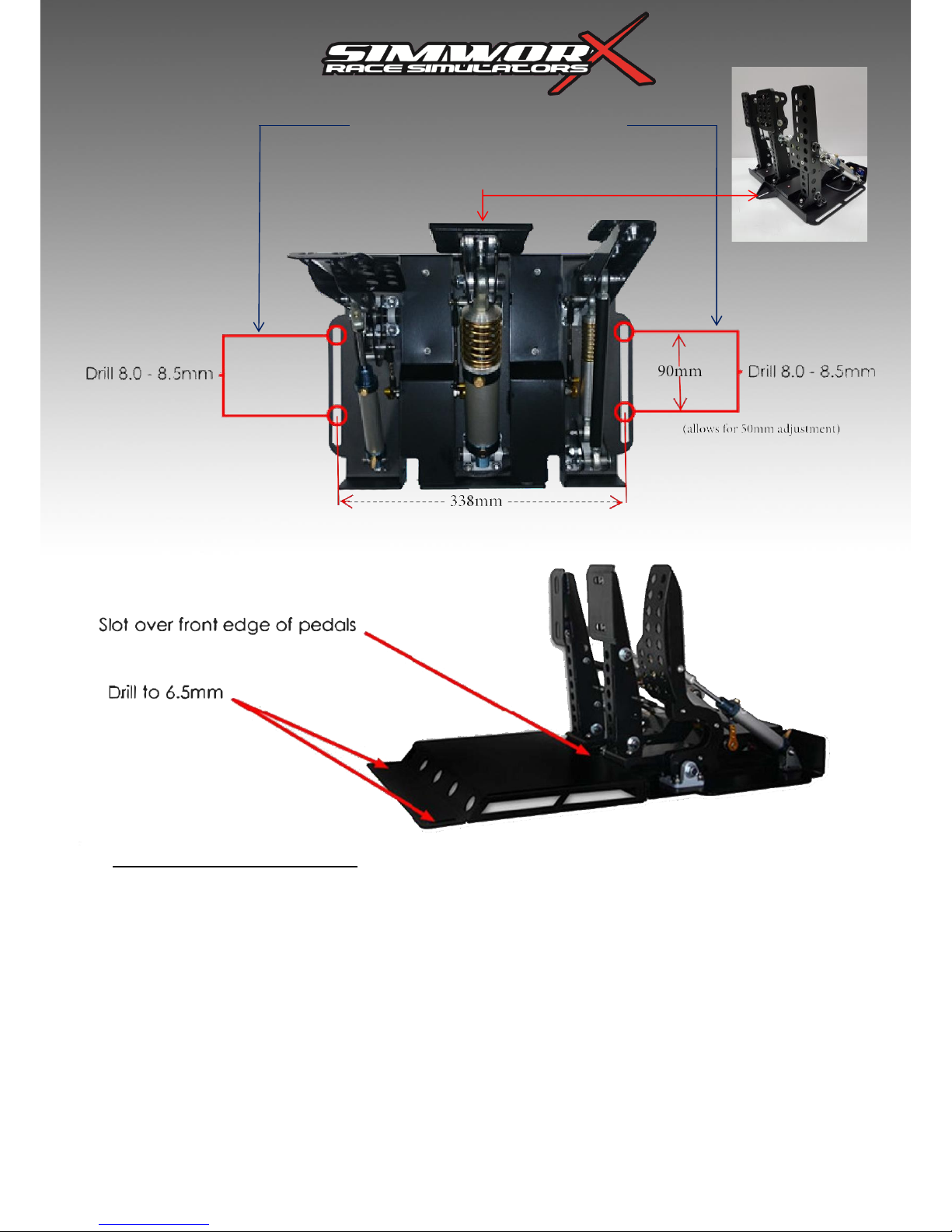
Please note: Heel plate is optional.
Drill and locate these holes first
Once located in final position mark and drill
The front bolt hole last
Heel Plate
Page 4
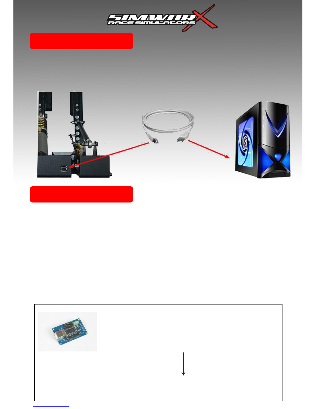
Plug in the supplied USB A to B cable into the rear of the pedal set and then into a spare USB port
on your computer. The pedal set should be automatically be detected by Windows and self-install.
You can confirm this by going to the ‘devices and printers” and confirming that “Simworx Pro
Series” is listed there. If its not listed, try another USB port on the computer end.
This procedure is based on the windows 7/8.1/10 operating system, older systems may vary.
1. Once you have connected your pedals and the “Simworx Pro Series” device is visible in windows “Devices and
Printers”, right click on the “Simworx Pro Series” and select “Game Controller Settings
2. From the next list, select “Simworx Pro Series” and click the “Properties” button.
3. Click the “Settings” tab in the next window.
4. Click “Reset to default”
5. Click “Calibrate”
6. Follow the on screen prompts to calibrate your device
7. Once completed, you will be taken to the testing window, press all the pedals and watch the
visible red sliders to confirm calibration, if the red sliders do not travel the full extent, repeat from step 3.
Once correctly calibrated you can run your game and configure your in game controls.
Alternatively there is a Leo Bodnar Calibration exe file DIView.exe - For Accurate Calibration that is available for
download from his website:
CONNECTION
CALIBRATION
BU0836-LC Load Cell Joystick Controller
Click Here to DIView.exe download
Product Description More Details How to Use Product Downloads Additional Images
Page 5
Pedal Face Angle
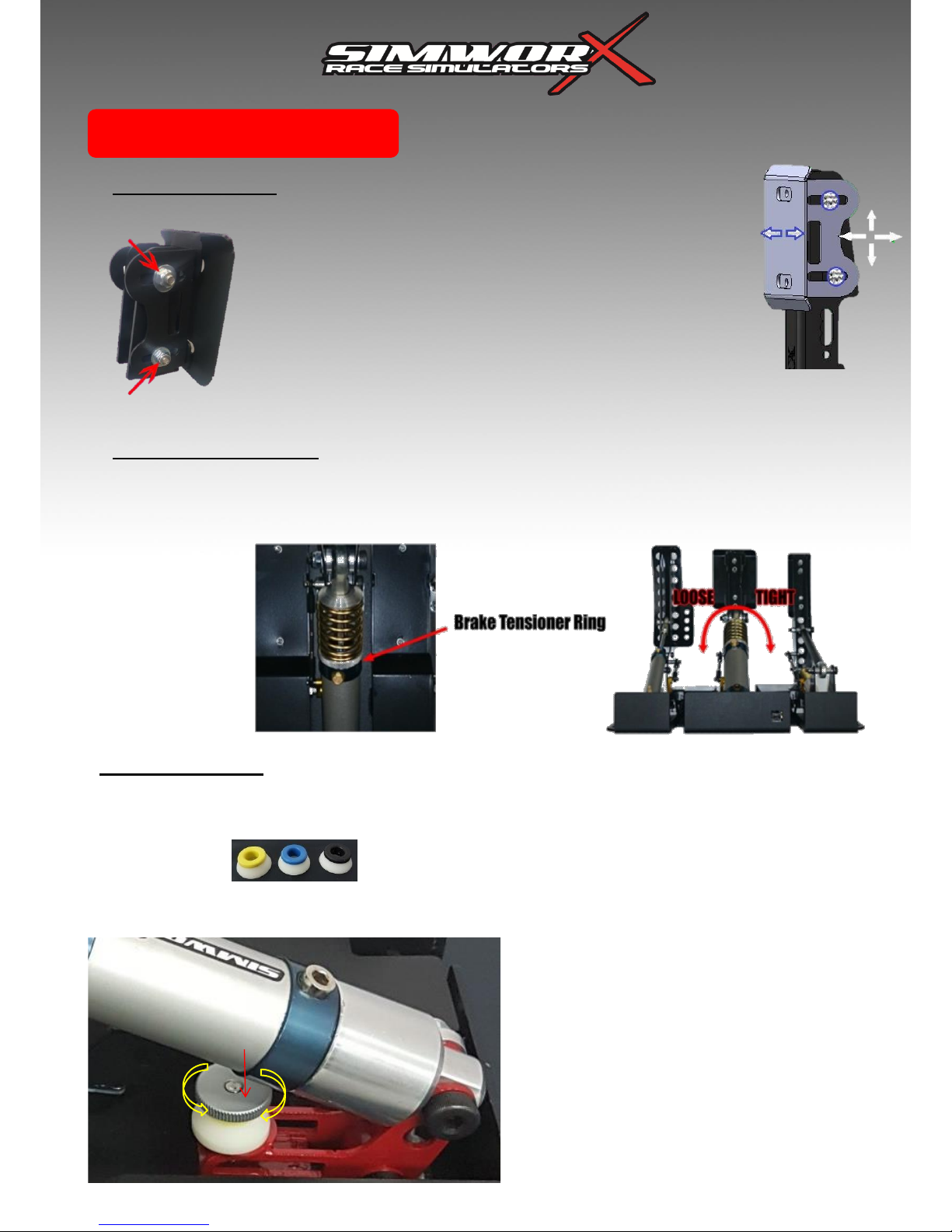
The pedal face on both the clutch and brake pedals are fitted
with angle and height adjustments. To adjust, using a 5mm allen
key and 10mm spanner, loosen off the two nuts (pointed out by
the red arrows) a few turns to loosen the pad assembly. Once
loose, you will be able to adjust the pad upwards & down, as
well as tilt the pedal face backward and forwards until you’re
comfortable with the position.
Once you’re satisfied with the position, tighten up the bolts
firmly to ensure that the pad does not move under load.
Brake Tensioner Ring
The brake cylinder is fitted with a dedicated spring tensioner for adjusting the initial preload to the brake
pedal to mimic the initial pad travel to the rotor. This is useful for fine tuning that initial pedal travel. If
required, to adjust, hold the brake cylinder and spin the tensioner ring at the base of the brake spring.
Once the
tensioner ring
starts to feel
tight to turn, you
have reached
the maximum
tension point.
Do not try and
force the
tensioner ring
further .
ADJUSTMENTS
The brake assembly can be adjusted for brake
stroke / tension. With three settings. Soft, Medium
& Hard. Each setting changes the amount of
braking force & travel of the pedal. You will be
supplied with three Urethane dampers. Our default
damper is medium (yellow) which is fitted as
standard and the soft and hard dampers are
supplied in a box with your pedals. The softest
damper is the Blue colour cap and the hardest is
the Black colour capped Damper. The softest
damper set provides the most travel and softest
feel, whereas the hard damper setting provides a
short travel with a very firm pedal. You can also
adjust the feel with the thumb wheel by screwing it
in and out. To fit the alternative damper, unscrew
the thumb wheel and replace the damper making
sure the thumbwheel flange locates inside the
Damper bore to locate it centrally.
Load Cell Rocker Arm Dampers
Yellow Blue Black
Medium Soft Hard
Thumbwheel
Loosen Tighten
Brake Pedal Feel
The pedals come with three urethane dampers of various durometers that act on the Load Cell Cylinder Rocker
Arm. The thumbwheel enables the pedal feel to be infinitely adjustable. As standard, the medium grade damper is
fitted. To change the dampers, if needed, is a very simple process as outlined below..
Damper Rocker Arm
Page 6
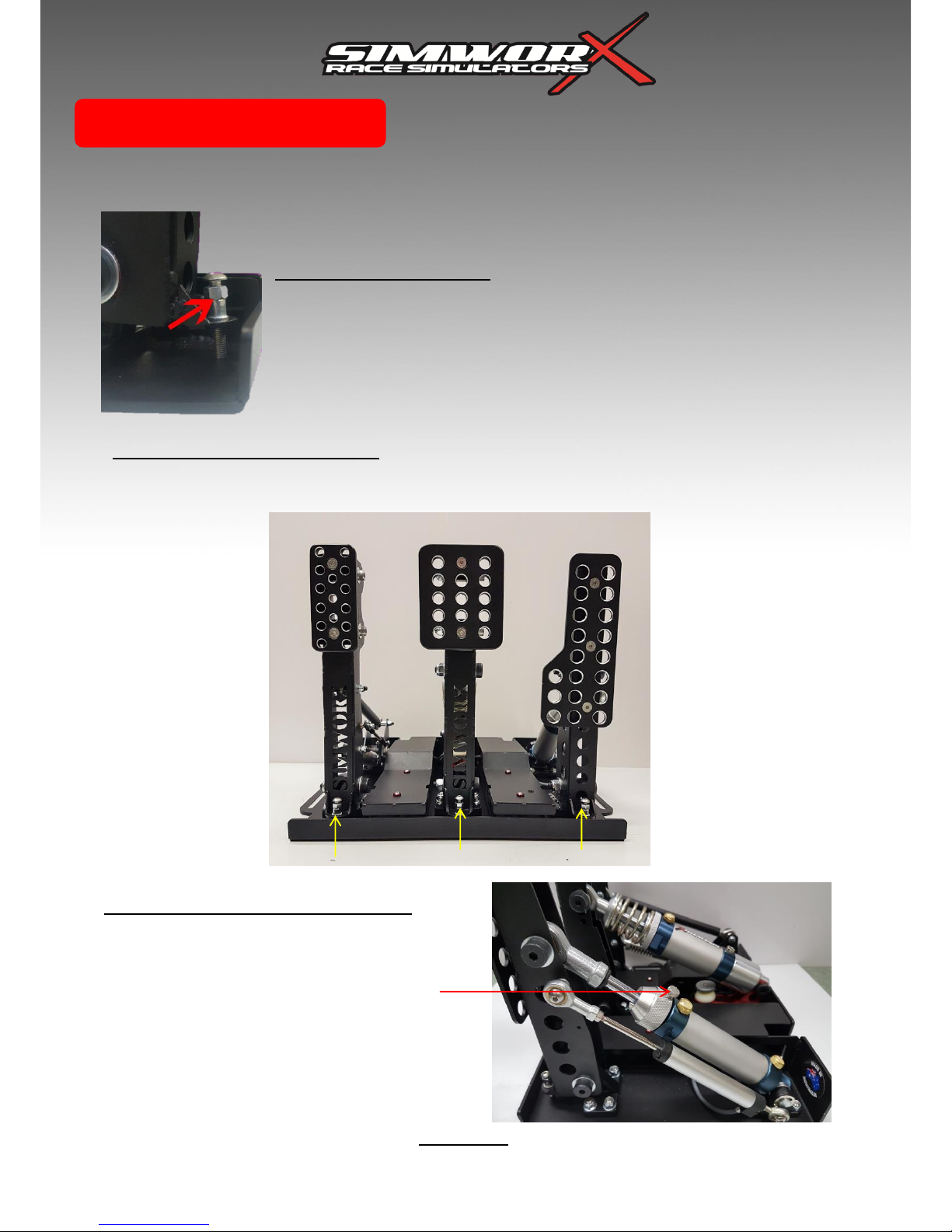
Pedal Rebound Adjust
After any adjustment, you may need to alter the pedal rebound to get the
pedal sitting nicely again. To do this, use an 8mm spanner to loosen the
locking nut (pointed out by the red arrow) then use a 3mm allen key to
adjust up or down the stop until the pedal is in your desired position. Once
you’re happy with the position, tighten the locking nut firmly.
Pedal Rebound Adjustment
If required, your pedals are fitted with an adjustable set point that can be changed using a 3mm
allen key and an 8mm spanner.
Please Note:
After any of these adjustments, you will need to go through the calibration process again.
ADJUSTMENTS
Pedal Set Points are adjusted via the screw stops at the base of the pedals
Accelerator Pedal Stroke Adjust
The accelerator pedal stroke can be adjusted for a
shorter stroke by rotating the alloy adjuster at the top
of the cylinder. Undo the thumbscrew on the adjuster,
rotate the adjuster to your desired position. Once
satisfied re-tighten the thumbscrew.
Once you’re totally satisfied with it’s stroke length don’t
forget to recalibrate the accelerator axis.
Page 7

Problem: ‘In the game, my car doesn’t brake / accelerate effectively’
Solution: Recalibrate the pedal set in the windows game devices and re assign them in game.
Problem: ‘My pedal set is not detected by windows’
Solution: Try an alternative USB port on the computer, Listen for the audible ‘connect/disconnect’ noise
from windows. Alternatively try a different USB cable.
If you have any problems installing/calibrating or setting up your Pro GT pedal set, contact SimworX
support on the below email or give us a call and are more than happy to assist.
We appreciate your feedback, any feedback relayed via Facebook or email is greatly appreciated.
SimworX Simulators
1/3 Nicole Close, Bayswater North
Victoria, Australia 3153
PH: +61 3 9761 5093
Sales: [email protected]
Support: [email protected]
Web: www.simworx.com.au
TROUBLESHOOTING
 Loading...