

Page 1
P/N: 850-816926-EN Rev6
Operating Manual
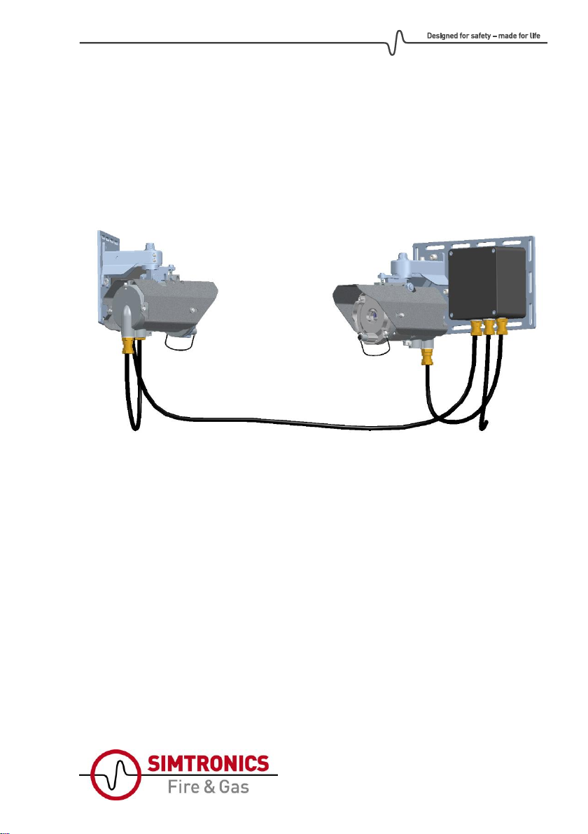
Simtronics GD1 MK3
Toxic Open Path Gas Detector
Page 2

GD1 Page 2 of 76 850-816926-EN R06
Copyright June 2018 by Simtronics A.S.
All rights reserved. No reproduction of all or part of this document, in any form, is permitted
without the written consent of Simtronics A.S.
All of the information that is provided in this document is accurate to the best of our
knowledge.
As a result of continuous research and development, the specifications of this product may
be changed without prior notice.
Simtronics A.S.
Kabelgaten 8, Økern Næringspark
PO Box 314, Økern, NO-0511 Oslo, Norway
https://gasdetection.3M.com
Page 3

GD1 Page 3 of 76 850-816926-EN R06
Thank you for choosing this SIMTRONICS instrument.
All of the necessary actions have been taken in order to ensure your complete satisfaction
with this equipment.
It is important that you read this entire manual carefully and thoroughly.
Limitation of Liability
The Company SIMTRONICS A.S., hereinafter referred to as “SIMTRONICS” throughout
this document, shall not be held responsible for any damage to the equipment or for
any physical injury or death resulting in whole or in part from the inappropriate use or
installation of the equipment, non-compliance with any and all instructions, warnings,
standards and/or regulations in force.
No business, person or legal entity may assume responsibility on behalf of
SIMTRONICS, even though they may be involved in the sale of SIMTRONICS products.
SIMTRONICS shall not be responsible for any direct or indirect damage, or any direct or
indirect consequence, resulting from the sale and use of any of its products UNLESS
SUCH PRODUCTS HAVE BEEN SELECTED BY SIMTRONICS ACCORDING TO THE
APPLICATION.
Ownership clauses
The drawings, specifications, and information herein contain confidential information
that is the property of SIMTRONICS.
This information shall not, either in whole or in part, by physical, electronic, or any
other means whatsoever, be reproduced, copied, divulged, translated, or used as the
basis for the manufacture or sale of SIMTRONICS equipment, or for any other reason
without the prior consent of SIMTRONICS.
Warning
This is not a contractual document. In the best interest of its customers and with the
aim of improving performance, SIMTRONICS reserves the right to alter the technical
features of its equipment without prior notice.
READ THESE INSTRUCTIONS CAREFULLY BEFORE THE FIRST USAGE: these instructions
should be read by all persons who have or will have responsibility for the use,
maintenance, or repair of the instrument.
This instrument shall only be deemed to be in conformance with the published
performance if used, maintained, and repaired in accordance with the instructions of
SIMTRONICS by SIMTRONICS personnel or by personnel authorized by SIMTRONICS.
Page 4

GD1 Page 4 of 76 850-816926-EN R06
Important Information
The modification of the material and the use of parts of an unspecified origin shall
entail the cancellation of any form of warranty.
The use of the unit has been projected for the applications specified in the technical
characteristics. Exceeding the indicated values cannot in any case be authorized.
SIMTRONICS recommends regular testing of fixed gas detection installations (read
Chapter 6).
Warranty
The GD1 comes with a 5 year limited warranty on the product. The warranty covers
correct function inside specified tolerances. Warranty is void if the detector has been
installed or operated in conflict with specifications and procedures given in this
operating manual.
Destruction of the equipment
European Union (and EEA) only. This symbol indicates that, in conformity with
directive DEEE (2002/96/CE) and according to local regulations, this product may
not be discarded together with household waste.
It must be disposed of in a collection area that is set aside for this purpose, for
example at a site that is officially designated for the recycling of electrical and
electronic equipment (EEE) or a point of exchange for authorized products in the event of
the acquisition of a new product of the same type as before.
Page 5

GD1 Page 5 of 76 850-816926-EN R06
TABLE OF CONTENTS
1. Introduction ................................................................................................................... 7
1.1. The system ........................................................................................................ 7
1.2. Definitions ......................................................................................................... 7
2. Installation ..................................................................................................................... 9
2.1. System parts ...................................................................................................... 9
2.2. Positioning ....................................................................................................... 10
2.3. Mounting ......................................................................................................... 10
2.3.1. Mounting on pole ......................................................................................... 11
2.4. Sun shielding ................................................................................................... 11
2.5. Electrical connection and wiring...................................................................... 12
2.5.1. Alternative wiring configurations ................................................................. 15
2.5.2. Cable types and specification ....................................................................... 16
2.5.3. Earth connection .......................................................................................... 16
2.5.4. Performing loop test .................................................................................... 17
3. Commissioning............................................................................................................. 21
3.1. Preparation ...................................................................................................... 21
3.2. Coarse alignment ............................................................................................. 21
3.3. Fine tuning ....................................................................................................... 23
3.3.1. Using a Web browser for tuning of signal strength ...................................... 23
3.3.2. Using a HART® for tuning of signal strength ................................................. 30
3.4. Function test .................................................................................................... 35
3.4.1. Performing function test with CO2 as a non-toxic alternative ...................... 36
4. Operation ..................................................................................................................... 39
4.1. Analogue Output Protocol ............................................................................... 39
4.2. Test Cell filling and emptying instructions ....................................................... 40
5. Maintenance ................................................................................................................ 41
5.1. Regular maintenance....................................................................................... 41
5.2. Cleaning of optical surfaces ............................................................................. 41
6. Troubleshooting........................................................................................................... 43
6.1. Error codes ...................................................................................................... 45
6.2. Tuning detector for less noise ......................................................................... 46
6.3. Interference from another GD1 ...................................................................... 48
6.4. Download the Diagnostics file ......................................................................... 48
6.5. Uploading a Configuration file ......................................................................... 49
Page 6

GD1 Page 6 of 76 850-816926-EN R06
7. Certifications and standards ....................................................................................... 53
7.1. Certification .................................................................................................... 53
7.2. Marking ........................................................................................................... 53
7.3. Specific condition for use in Explosive Atmosphere “X” ................................. 53
8. Accessories and spare parts ........................................................................................ 55
8.1. Ordering information for the GD1 .................................................................. 57
9. Technical Specifications .............................................................................................. 59
10. System description ...................................................................................................... 61
10.1. System ............................................................................................................ 61
10.2. Application areas ............................................................................................ 62
10.3. Positioning considerations .............................................................................. 63
10.3.1. General positioning considerations regarding a gas cloud ..................... 63
10.4. Detection principles ........................................................................................ 64
10.5. How to connect to the web interface with the Ethernet cable ...................... 65
10.6. Data logging functionality ............................................................................... 67
11. Support and contact details ........................................................................................ 71
11.1. Shipping instruction sending units to support ................................................ 71
EU Declaration of conformity............................................................................................... 75
Page 7
GD1 Page 7 of 76 850-816926-EN R06
1. INTRODUCTION
1.1. The system
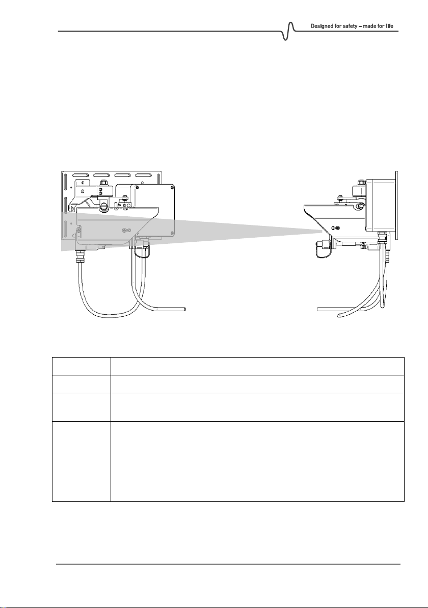
The GD1 is a laser-based open path Gas Detector with a separate transmitter (TX) and
receiver (RX). The TX emits infrared laser light detected by the RX. The detection principle
is based on measuring the absorption of light by the gas molecules along the optical lineof-sight.
RECEIVER TRANSMITTER
1.2. Definitions
TX
Transmitter
RX
Receiver
Absolute
transmission
Strength of the optical signal
Relative
transmission
The relative strength of the optical signal in percentage relative to the
Absolute transmission when finishing alignment.
During commissioning, the GD1 is set up with optimum alignment and
signal strength. The relative transmission is used to keep track on how dirty
or out of alignment the system has become after the GD1 was
commissioned.
Laser light
Page 8

GD1 Page 8 of 76 850-816926-EN R06
THIS PAGE LEFT INTENTIONALLY BLANK
Page 9
GD1 Page 9 of 76 850-816926-EN R06
2. INSTALLATION
The area in which the detector may be installed must be in accordance
with the certification of the detector and in accordance with the
standards of the appropriate authority in the country of installation.
2.1. System parts
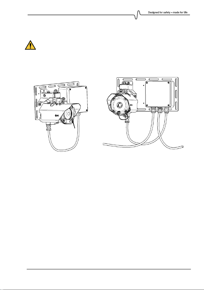
RECEIVER TRANSMITTER
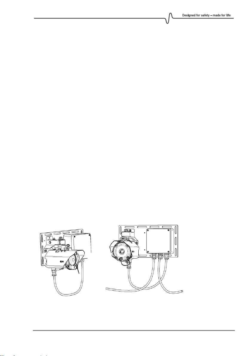
The complete GD1 system consists of a TX sending a laser beam to the RX. Communication
to control room and power to the GD1 is connected to the TX. Between the TX and RX
there is a cable with communication and power.
The TX where the laser is located sends a diffused light beam (invisible) to the receiver. The
beam is shaped as a cone, not a focused laser beam as you might expect from a laser
pointer. The TX comes complete with the TX and junction box mounted on a backing plate.
The RX has a larger optical aperture to collect the transmitted light and add margin to path
alignment. The TX and RX communicate on a data link (cable). The RX comes complete with
the RX and junction box mounted on a backing plate.
Page 10
GD1 Page 10 of 76 850-816926-EN R06
2.2. Positioning
Deciding on how the GD1 detectors should be placed at the site is discussed in section
10.3. During installation the detector should be positioned according to the following
points:
• Check that there is a free line of sight between the TX and RX.
• The measuring path should be horizontal.
• Avoid that the measuring path is blocked by temporary scaffolding, parked cars,
high traffic and moving structures.
• The detector should be attached to a mechanically rigid structure.
• The GD1 should be positioned as to avoid more than one TX transmitting into a RX.
Failing to do this can lead to interference between the detectors and false alarms.
• The transmitter and receiver units are to be fitted perpendicular to the measuring
path, within ± 20 degrees.
2.3. Mounting
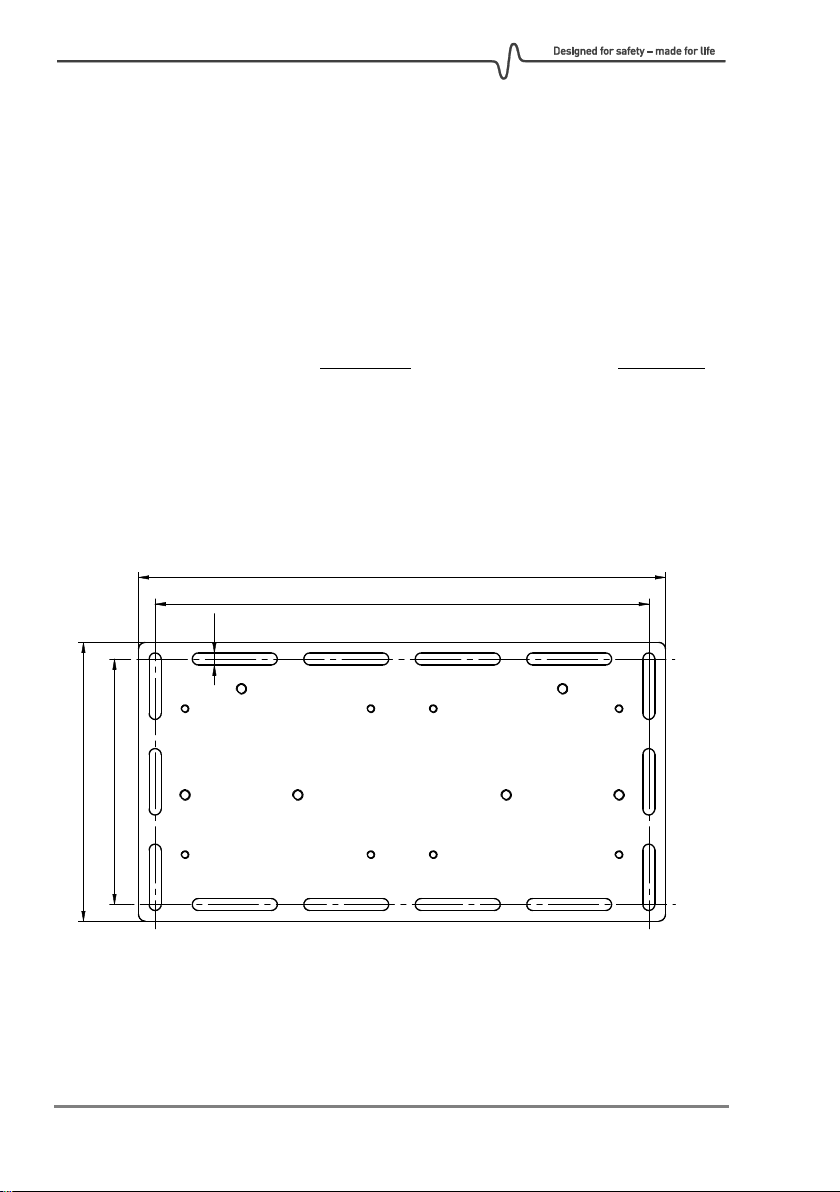
The GD1 Transmitter and Receiver system assemblies are delivered on a 6mm (1/4")
universal mounting plate suitable for most mounting situations. See figure below for
general dimensions (mm).
The transmitter and receiver units are to be mounted perpendicular to the measuring path,
within ± 20 degrees.
397
210
185
9
372
Page 11
GD1 Page 11 of 76 850-816926-EN R06
2.3.1. Mounting on pole
If the detector is mounted on a pole/pipe, it is important that the pole/pipe is structurally
rigid enough that the detector will not move out of its alignment tolerances. When
choosing pole diameter, one must account for mounting height. Simtronics recommends
that for a mounting height of 2m, minimum Ø 3” (75 mm) pole is used for sufficient rigidity.
If mounting height is increased, pole/pipe diameter should increase accordingly.
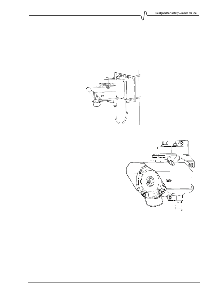
2.4. Sun shielding
The transmitter and receiver are fitted with a
sun shield as standard.
In locations where there is a risk that the
temperatures can exceed the certified limits for
the ambient temperature, a canopy can be
mounted above the detector for additional sun
shielding.
It is not recommended to store a GD1 for a long
time un-powered outside in a hot environment.
If the detector is stored unpowered in high
temperatures for several months, it might lead
to settings needing adjustment.
Page 12
GD1 Page 12 of 76 850-816926-EN R06
2.5. Electrical connection and wiring
Make sure that power is disconnected or switched off before connecting any wires.
The system supplying power to the GD1 shall have a fuse allowing maximum 1 A of
current to enter the GD1.
The detector must be earthed for electrical safety and to limit the effects of radio
frequency interference. Earth connection points are provided on the underside of the
GD1 housing and inside the Junction Box.
The connection terminals are accessed by removing the covers of the junction boxes.
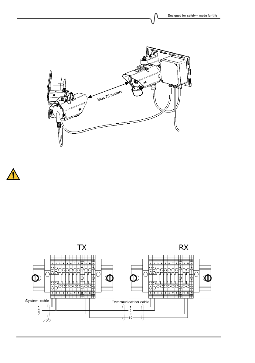
Wiring diagrams are shown below. The system cable only goes to the transmitter unit. The
cable between the junction boxes carries the power to the receiver and the
communication signals. Unless otherwise instructed, please observe that the system power
and analogue output cable is terminated on the transmitter side of the GD1 system.
Page 13

GD1 Page 13 of 76 850-816926-EN R06
Wiring overview Transmitter Junction Box:
System
cable
Terminal
Cable from GD1
instrument
Wire color
Transmitter Junction Box
Com. cable
+24 VDC
1
White
+24 VDC
+24 VDC
0 V Return
(GND)
2
Brown
0 V Return
0 V Return
(GND)
3 Green
Ethernet®
4 Yellow
Ethernet®
5 Black
Ethernet®
6
Violet
Ethernet®
Signal to
control
room
7
Blue
4-20 mA primary gas value and
HART®.
Default is source configuration
with 4-20 mA measured
between terminals 7 and 2 (0V).
For sink configuration 4-20 mA
is measured between terminals
7 and 1 (24 V).
8
Red
Secondary current loop:
Relative transmission
(configurable).
PE - Earth
11*
Gray
TxRx Com 1 from Rx
TxRx Com 1
12*
Pink
TxRx Com 2 from Rx
TxRx Com 2
PE - Earth
Note! Instrument damage can occur if incorrectly connected.
* Wires to terminal 11 and 12 shall be twisted.
Page 14

GD1 Page 14 of 76 850-816926-EN R06
Wiring overview Receiver Junction box:
System
cable
Terminal
Cable from GD1
instrument
Wire color
Receiver Junction Box
Com. cable
1 White
+24 VDC from Tx
+24 VDC
2 Brown
0 V Return from Tx
0 V Return
(GND)
3 Green
Do not connect.
4 Yellow
Do not connect.
5 Black
Do not connect.
6 Violet
Do not connect.
7 Blue
Tertiary current loop: Relative
transmission (configurable).
8 Red
Do not connect.
PE - Earth
11*
Gray
TxRx Com 1 from Tx
TxRx Com 1
12*
Pink
TxRx Com 2 from Tx
TxRx Com 2
PE - Earth
Note! Instrument damage can occur if incorrectly connected.
* Wires to terminal 11 and 12 shall be twisted.
Page 15
GD1 Page 15 of 76 850-816926-EN R06
2.5.1. Alternative wiring configurations
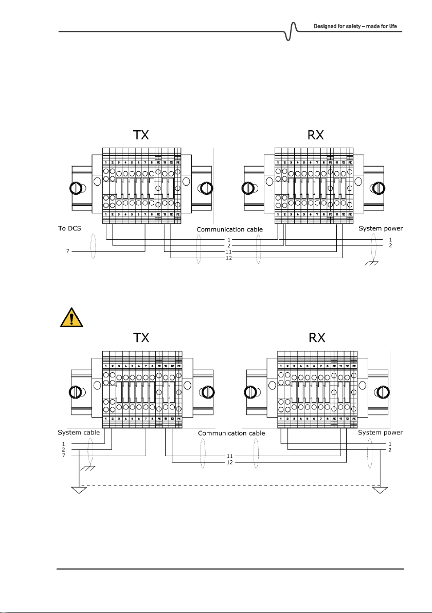
The default wiring configuration for the GD1 is with power and 4-20 mA connected to the
TX side, and with power supplied to the RX via the TX junction box.
Wiring alternative 1: System power connected on the receiver side
Wiring alternative 2: Power on both receiver and transmitter side
The instrument 0 V shall be the same for both RX and TX.
Page 16
GD1 Page 16 of 76 850-816926-EN R06
2.5.2. Cable types and specification
Cables must be chosen in accordance with applicable regulations.
System cable:
Cable from the GD1 system to control system. The table below indicates maximum cable
lengths (2-wire) restrictions due to voltage drop over the power supply cable.
Min. single wire cross area
0.75 mm2
1.25mm2
2.5 mm2
4.0 mm2*
Supply voltage 24 VDC, terminal 1.
Max length.
125 m
250 m
400 m
800 m*
Supply voltage 0 V Return on
terminal 2.
Max length.
Primary Loop, terminal 7.
The wiring should be such that the total
impedance of the current loop, including cabling,
connections and input on control system should be
maximum 500 .
*The GD1 is by default delivered with terminal blocks for wires up to 2.5 mm2.
TX / RX communication cable:
Cable between the GD1 Transmitter and Receiver, containing data and power supply. The
cable shall be an instrument type with 2 twisted, individually shielded pairs and with an
overall shield. Wiring up to 200 meters shall have a minimum cross section of 0.75 mm2.
For longer distances the maximum impedance of 70 must be considered.
2.5.3. Earth connection
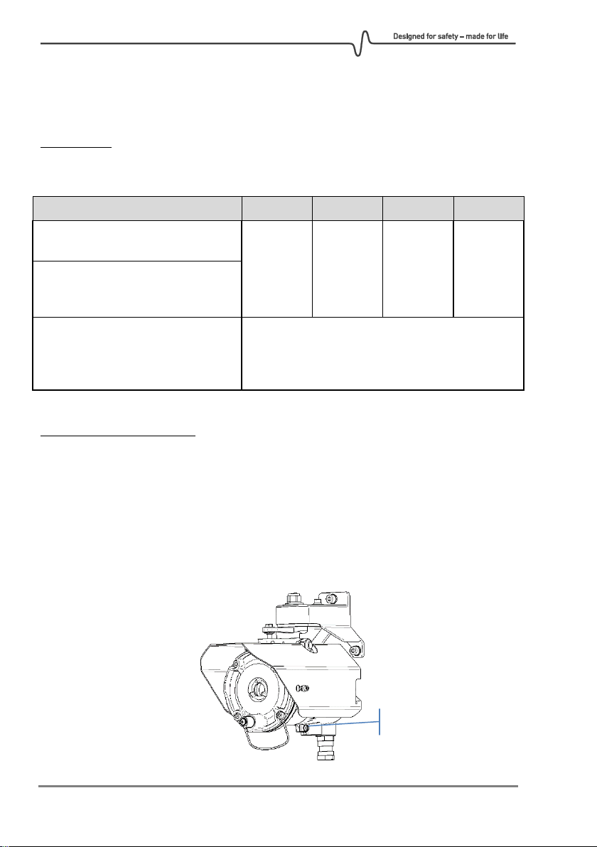
The detector housing must be connected to local earth via the external earth point. The
wire should be minimum 4 mm2 (8 AWG) and as short as possible.
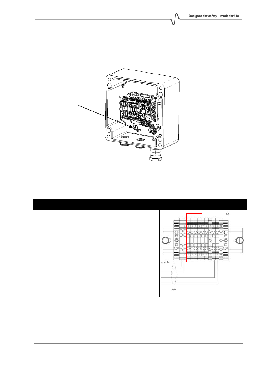
Earth point
Page 17
GD1 Page 17 of 76 850-816926-EN R06
The shield of the system cable should be connected to instrument earth in the central
control module, and is normally not terminated at the detector. Exception: If extra RFI
protection is required, and the installations grounding principles/regulations allows it, the
shield is terminated to local ground via the internal earth point at the detector instead.
2.5.4. Performing loop test
After powering up the GD1 a test can be performed of the 4-20 mA wiring. The loop test is
performed by the procedure below.
#
Description
Illustration
1
On the transmitter, connect the Ethernet adapter
to the Junction Box terminals 3 - 6.
Internal earth point
Page 18
GD1 Page 18 of 76 850-816926-EN R06
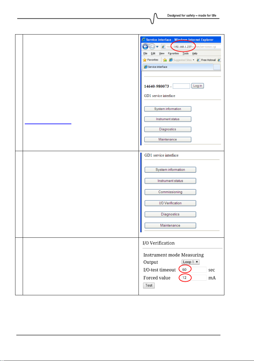
2
Use a device having Web browsing capabilities, for
example laptop, to connect with the wireless
router or Ethernet cable. If using the wireless
router, from your device connect to the network
SSID: “GD1”
In the web browser of your device, enter the GD1
Service Interface on the address
http://192.168.1.237
3
Log into the Service Interface with the Operator
password: "gd1tlc"
After logging in as Operator more functions are
accessible as illustrated in the right image.
4
Run loop testing in the Web interface "I/O
verification" screen.
Recommend to use at least 60 sec test time.
Enter forced value. For example 12 mA is 50% of
full scale.
Page 19

GD1 Page 19 of 76 850-816926-EN R06
5
When clicking “Test” the test value will be forced
on the 4-20 mA Loop1 terminal (terminal 7 in the
GD1 Junction Box).
Verify that the analogue output matches the test
value.
Page 20

GD1 Page 20 of 76 850-816926-EN R06
THIS PAGE LEFT INTENTIONALLY BLANK
Page 21
GD1 Page 21 of 76 850-816926-EN R06
3. COMMISSIONING
The commissioning of the GD1 consists of four steps:
• Section 3.1 Preparation.
• Section 3.2 Coarse alignment.
• Section 3.3 Fine tuning
• Section 3.4 Function test
3.1. Preparation
Before commissioning check that the following points are fulfilled:
• Commissioning should be carried out in clear weather in order to allow for correct
transmission settings.
• There is a free line of sight between the transmitter (TX) and receiver (RX).
• Check that optical surfaces on the detector and reflector are clean and dry.
• There should be no H
2
S gas present during commissioning.
Power up the GD1 system and let it warm up for 30 minutes before doing the final
alignment in section 3.3.
3.2. Coarse alignment
The objective for the coarse alignment is to set an initial transmission level. This signal level
is then used as a reference for further tuning, and a minimum signal level must be present
before fine alignment can be performed.
#
Description
Illustration
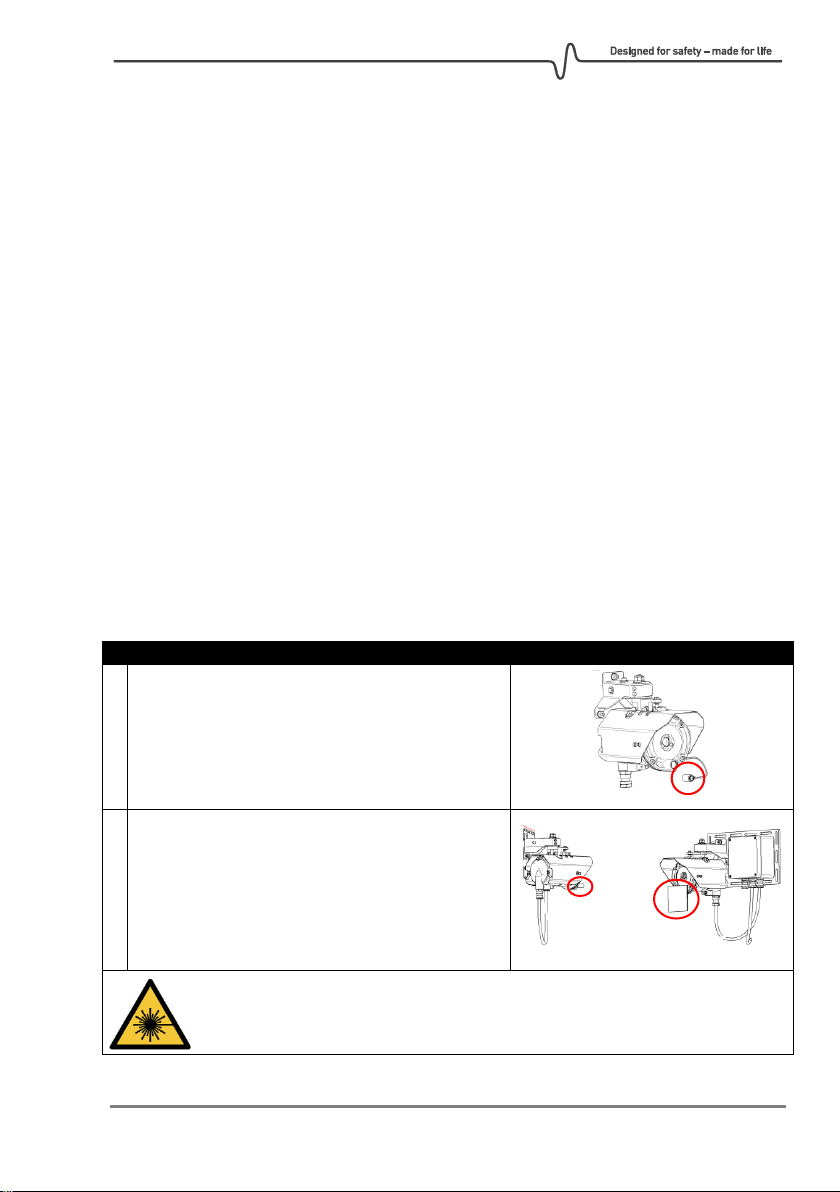
1
Clean the lens on the RX and TX and remove the
cover from the alignment slot.
2
Turn on Alignment Laser and insert into the RX
alignment slot, and the Laser Target Plate on the
TX side.
Do not stare directly into the Alignment Laser when it is operating. It is
recommended to use the laser safety glasses. In sharp sunlight, the glasses will
also make it easier to see the laser pointer.
Page 22
GD1 Page 22 of 76 850-816926-EN R06
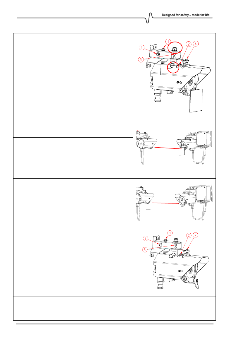
3
Loosen screws 2 and 3 on both the TX and RX.
Important: Nut A and nut on bolt B are
tightened correctly in the factory and should
not be touched. If tightened too much, they
may jeopardize the correct operation of
adjustment screws.
4
Rotate horizontally by hand so the RX and TX
points towards each other.
5
Adjust the RX with screws 4 (vertical direction)
and horizontal by hand until the laser spot hits
the target plate on the TX.
Tighten screws 2 and 3 fully on RX so it cannot
be moved by hand anymore.
6
Swap sides Alignment Laser and Laser Target
Plate so Alignment Laser now is attached to
the TX side.
7
Now adjust the TX with screws 4 (vertical
direction) and horizontal by hand until the
laser spot hits the target plate on the RX.
Tighten screws 2 and 3 fully on TX so it cannot
be moved by hand anymore.
8
Keep the Alignment Laser and Laser Target
Plate in place to assist in the Fine tuning
procedure.
Coarse alignment finished!
A
B
Page 23
GD1 Page 23 of 76 850-816926-EN R06
3.3. Fine tuning
Please be aware that the GD1 4 – 20 mA output going to control system is set to 2
mA during alignment, 1 mA during during power up and after reset to
measurement mode (Init).
Note! Poor alignment will reduce system performance. Use care to ensure good alignment.
Be aware that the nature of the GD1 system's laser beam implies a smaller target area than
with traditional open path systems, and higher alignment accuracy is needed to achieve
sufficient optical transmission levels.
Tuning of signal strength (transmission tuning) can be performed with two different
methods:
• Using a Web browser through an Ethernet connection. This is the preferred
method.
• Using a HART® terminal connecting through the 4-20 mA current loop (Primary
current loop) and a multimeter.
Both methods are explained in the two sections below.
3.3.1. Using a Web browser for tuning of signal strength
All functions for the GD1 Service Interface are described in section 10.5. The procedure for
fine alignment and transmission tuning is as follows:
#
Step description
Illustration
1
Clean the lenses of both transmitter (TX) and
receiver (RX) for any dirt before proceeding. The
optical path should be clear at the time of
aligning (avoid fog, mist, steam, rain, snow, etc.).
2
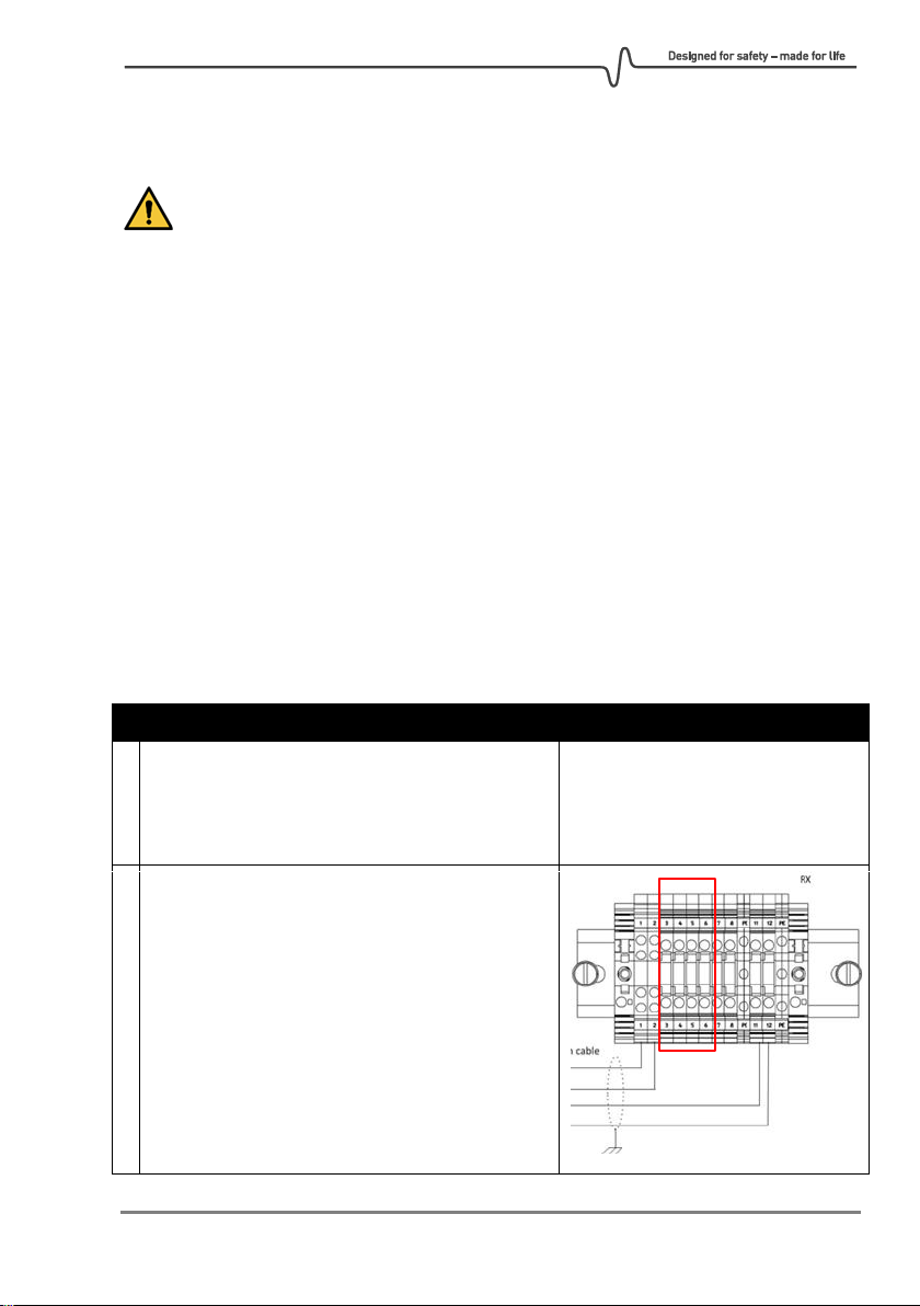
On the transmitter, connect the Ethernet
adapter to the Junction Box terminals 3 - 6.
Page 24
GD1 Page 24 of 76 850-816926-EN R06
3
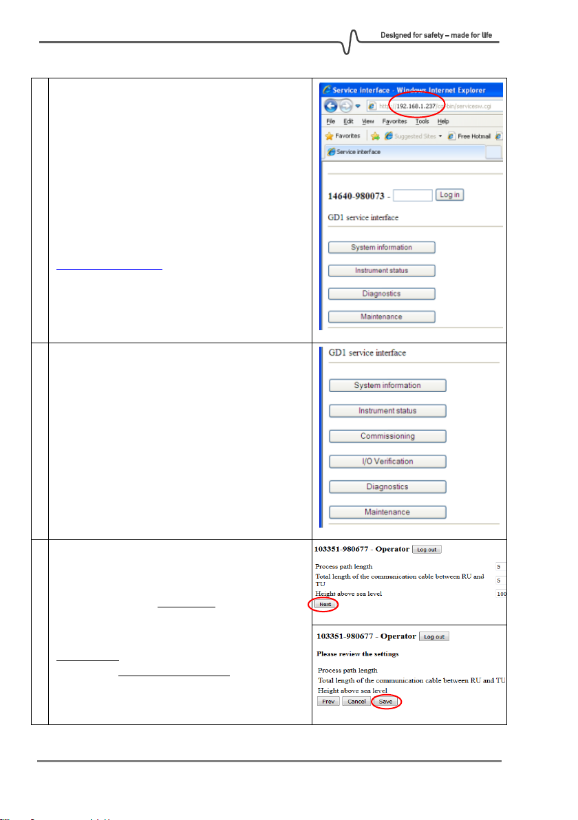
Use a device having Web browsing capabilities,
for example laptop, to connect with the wireless
router or Ethernet cable. If using the wireless
router, from your device connect to the network
SSID: “GD1”
In the web browser of your device, enter the
GD1 Service Interface on the address
http://192.168.1.237
4
Log into the Service Interface with the Operator
password: "gd1tlc"
After logging in as Operator more functions are
accessible as illustrated in the right image.
5
Click “Commissioning” followed by “Alignment”
to get into the alignment page.
Enter the parameters for path length, cable
length and altitude. Path length does not affect
the H2S measurement and is only used for
troubleshooting.
Cable length shall have a precision of better than
±100 m and height above sea level shall better
than ±300 meters.
Click “Next” followed by “Save”.
Page 25
GD1 Page 25 of 76 850-816926-EN R06
6
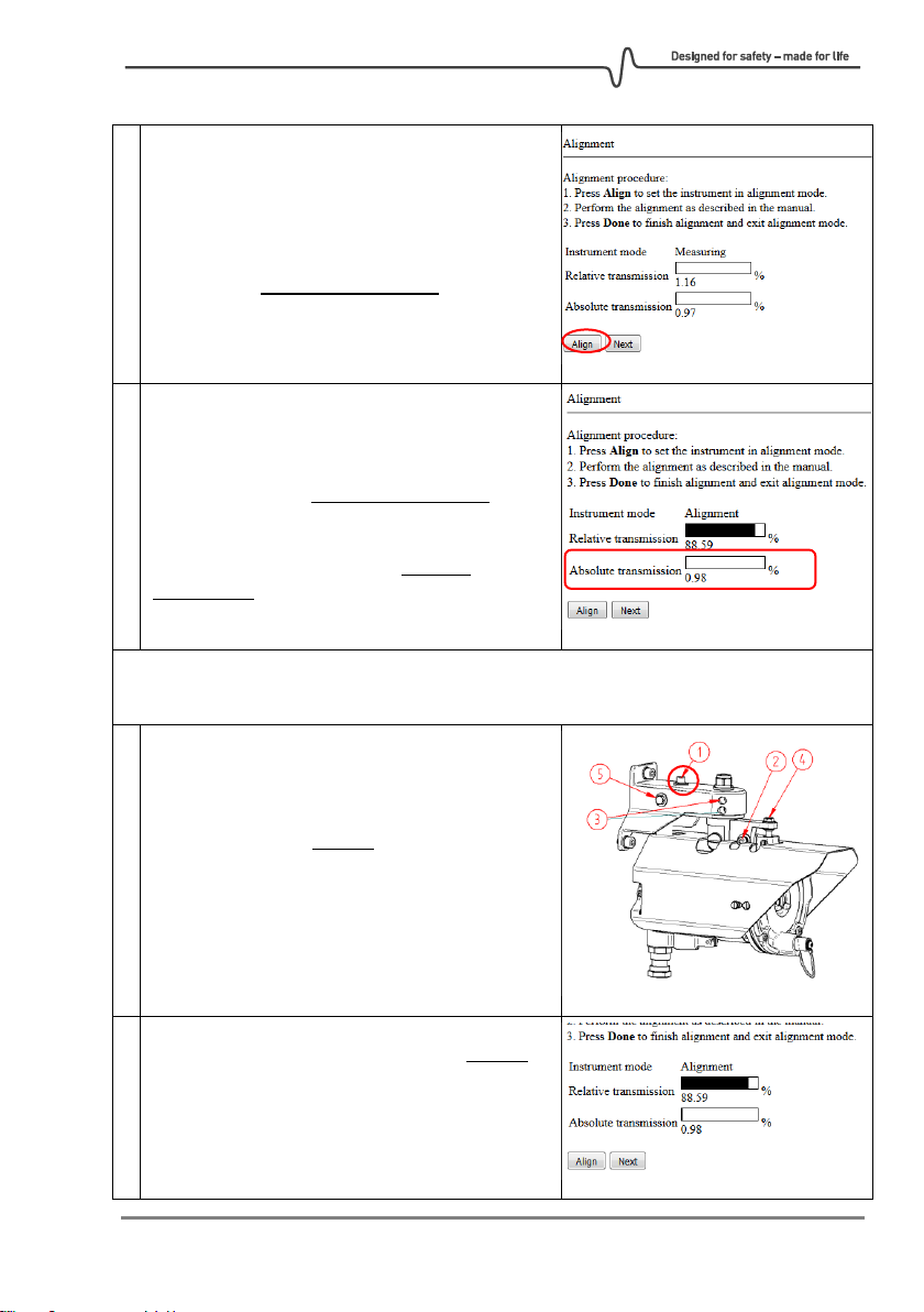
Clicking the “Align” button sets the system in
Alignment Mode. If sufficient laser light is
collected by the RX, the signal strength will be
shown in the Absolute transmission field.
7
The relative transmission is automatically set to
100% when entering alignment mode.
Notice that it is the Absolute transmission that
shall be optimized. The Relative transmission is
only used to assist in the alignment process since
it will “remember” the highest absolute
transmission seen since going into align mode.
A new reference can be set at any time by pressing “Align” again. This reference is than
used as 100% relative transmission until alignment is improved and is used as reference.
8
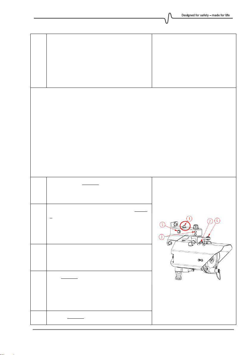
Slightly loosen only screw 1 just enough for the
alignment mechanism to be able to move in the
horizontal direction.
9
Align in horizontal direction by turning screw 5.
Turn very slowly in the direction whereby the
absolute transmission increases. The relative
transmission will stay close to 100% as long as
the absolute transmission is increasing.
Page 26
GD1 Page 26 of 76 850-816926-EN R06
10
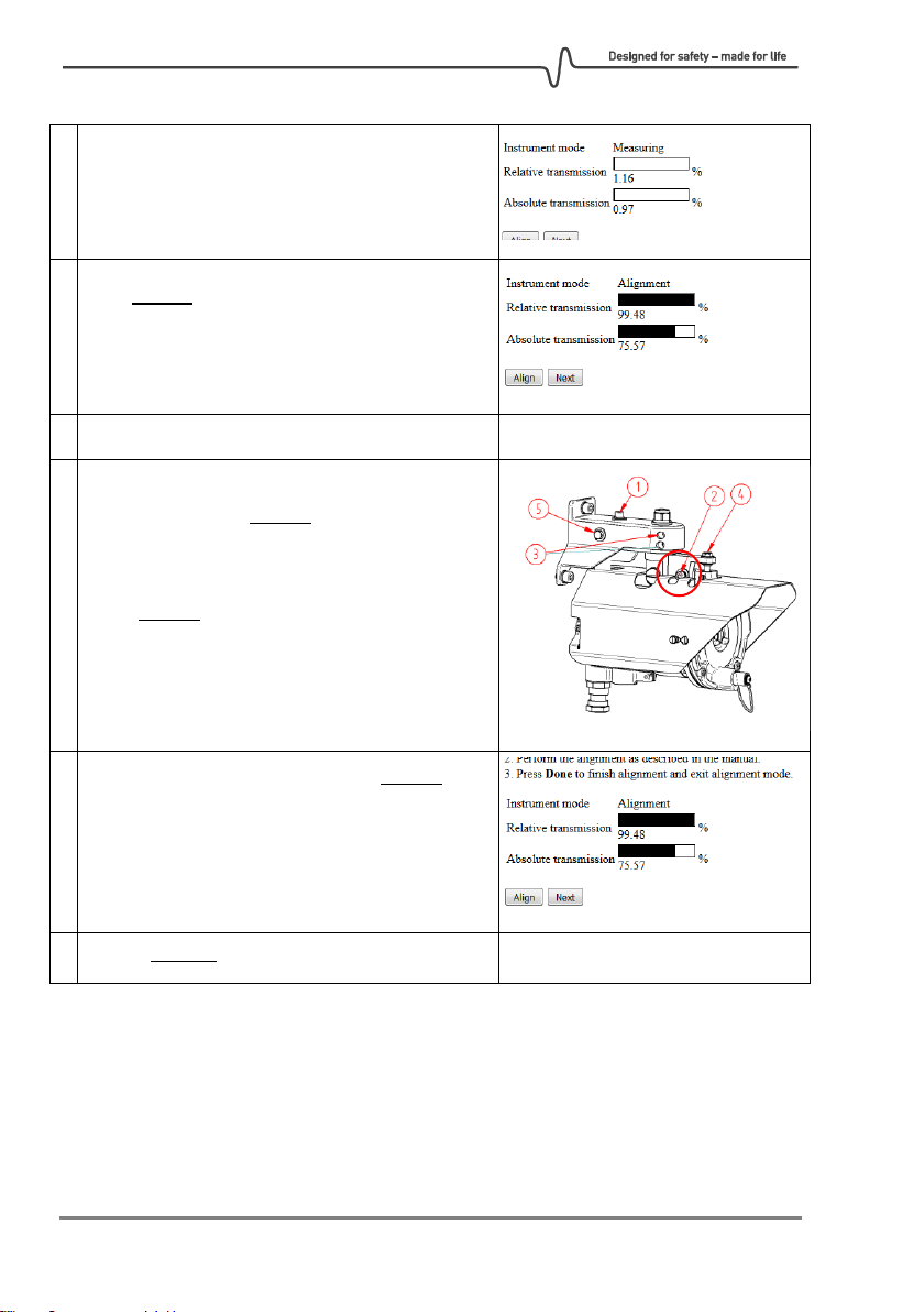
When continuing to turn the screw after the
maximum signal strength is reached, the
absolute and relative transmission will start to
drop.
11
Turn screw 5 back the other direction until the
relative transmission is better than 95%. This
should be close to the optimum position in the
horizontal direction.
12
Tighten screw 1.
13
Slightly loosen only screw 2 just enough for the
alignment mechanism to be able to move in the
vertical direction. Note that the absolute and
relative transmission will typically drop slightly
when screw 2 is loosened. If the values drop
significantly, it can be helpful to reset the
relative transmission to 100% again by clicking
the "Align" button.
14
Align in vertical direction by turning screw 4. As
for the horizontal alignment, turn very slowly in
the direction whereby the absolute transmission
increases. After reaching the maximum and the
signal starts to drop, turn back until the relative
transmission is better than 95%.
15
Tighten screw 2.
Page 27
GD1 Page 27 of 76 850-816926-EN R06
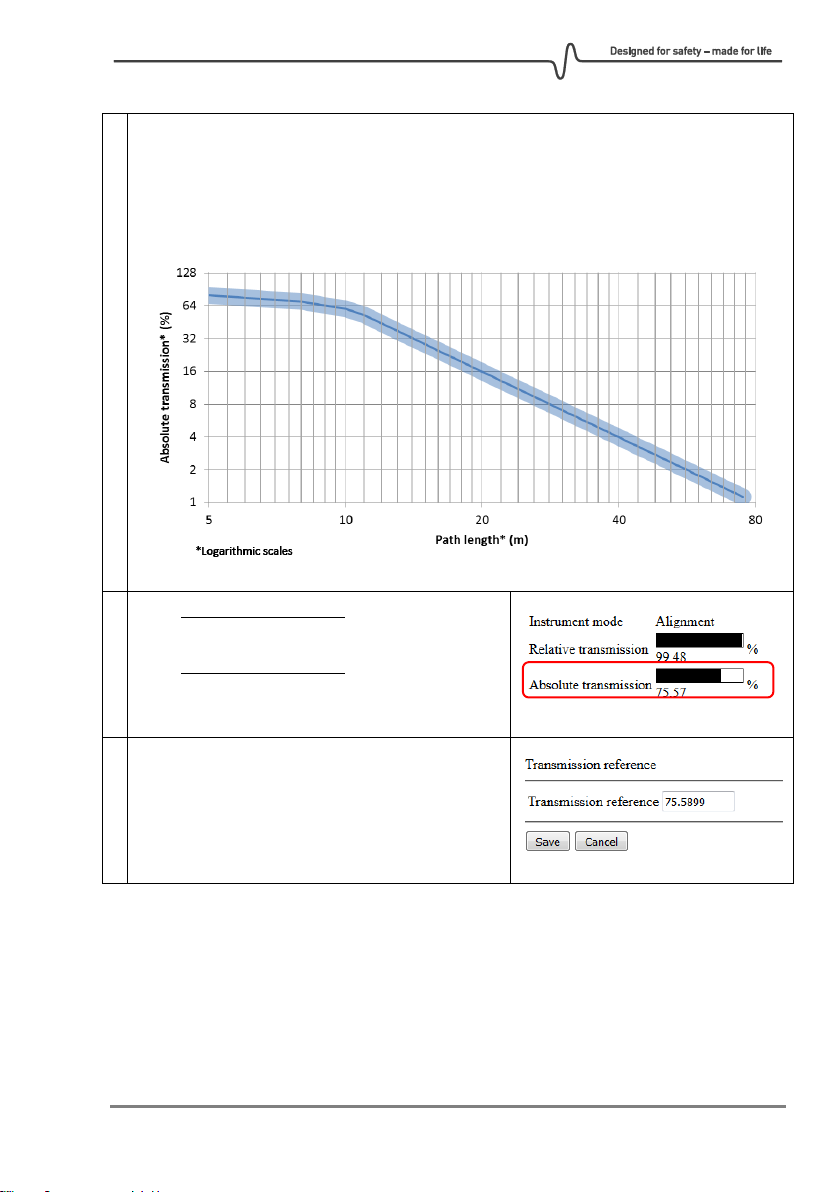
16
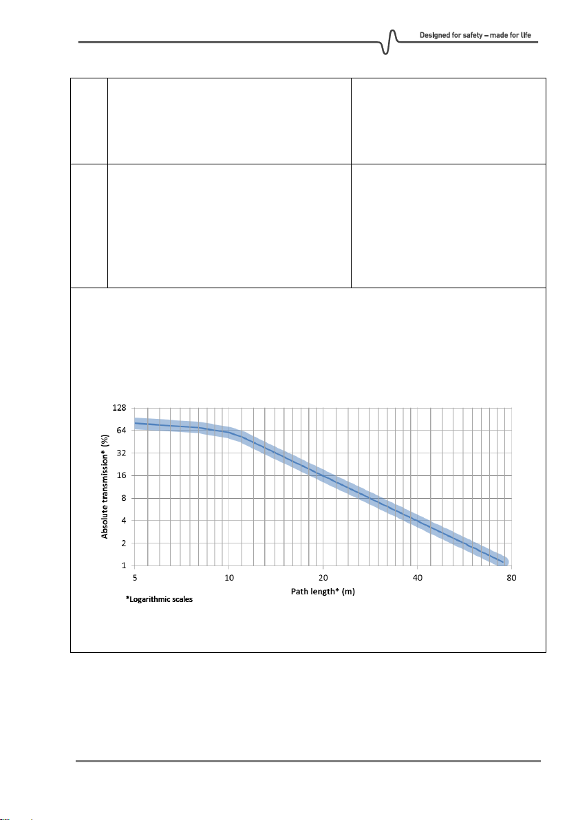
Check that the absolute transmission is as expected (indicated in the graph below). The
obtained absolute transmission can vary somewhat from detector to detector. If the
signal is significantly lower than the suggested values, this is an indication that the fine
alignment needs to be improved, the RX is poorly aligned or the lenses are dirty. The RX
is usually well enough aligned during the Coarse alignment, but this can also be a
reason for too low signal.
17
If the absolute transmission is acceptable click
DONE.
If the absolute transmission is significantly lower
than expected then also perform fine tuning for
RX in addition to the TX.
18
Click “Save”.
Page 28
GD1 Page 28 of 76 850-816926-EN R06
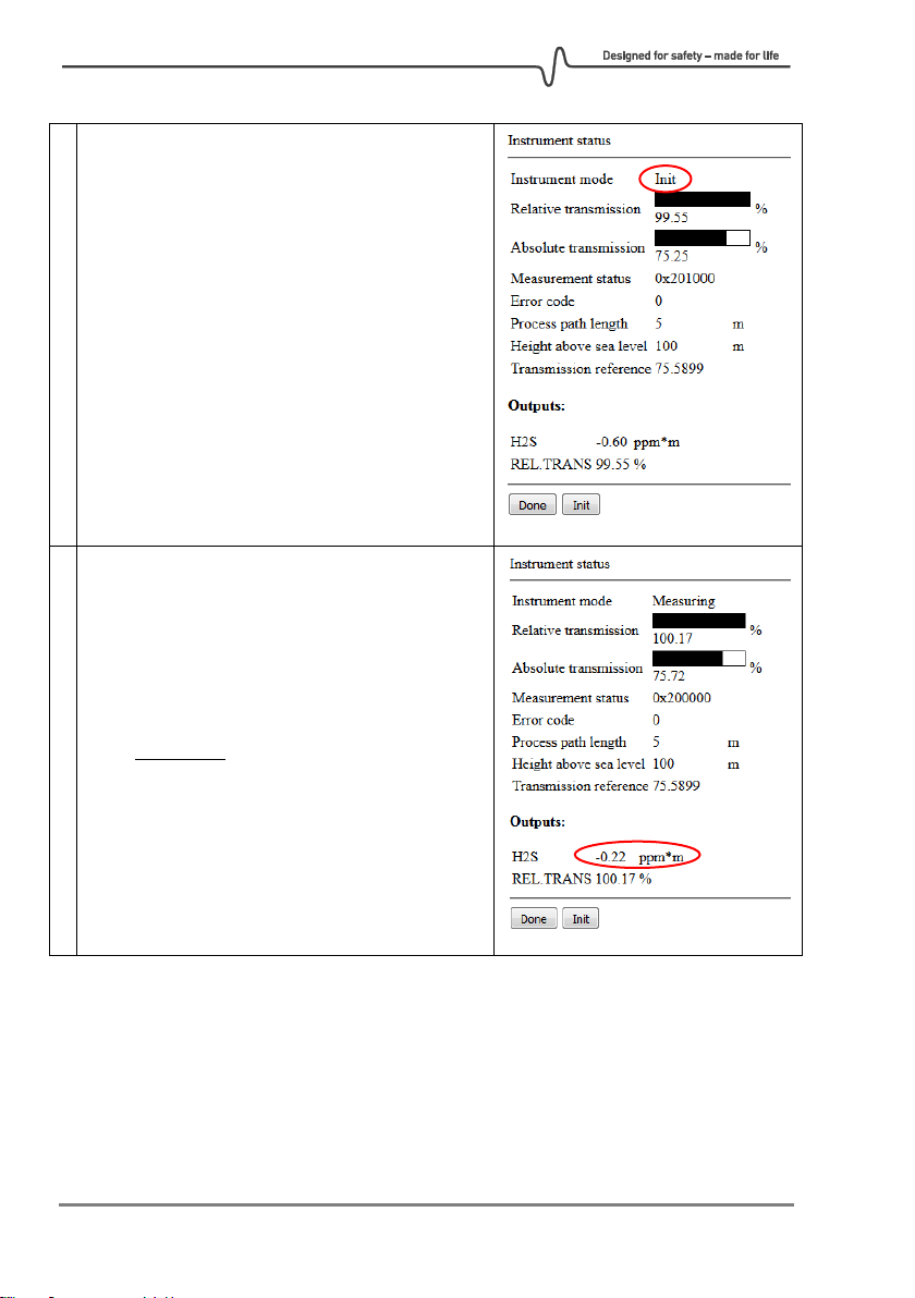
19
Enter the screen "Instrument status" and wait
for the GD1 to finish the Init procedure. In some
cases, it can take several minutes for “Init” to
finish.
20
When the GD1 is in Measuring mode check that
the noise level is OK by checking how the H2S
output is fluctuating. The H2S level can fluctuate
up to ± 8 ppm*m in normal conditions.
If the noise is at an acceptable level, step 21 to
23 can be omitted.
Page 29
GD1 Page 29 of 76 850-816926-EN R06
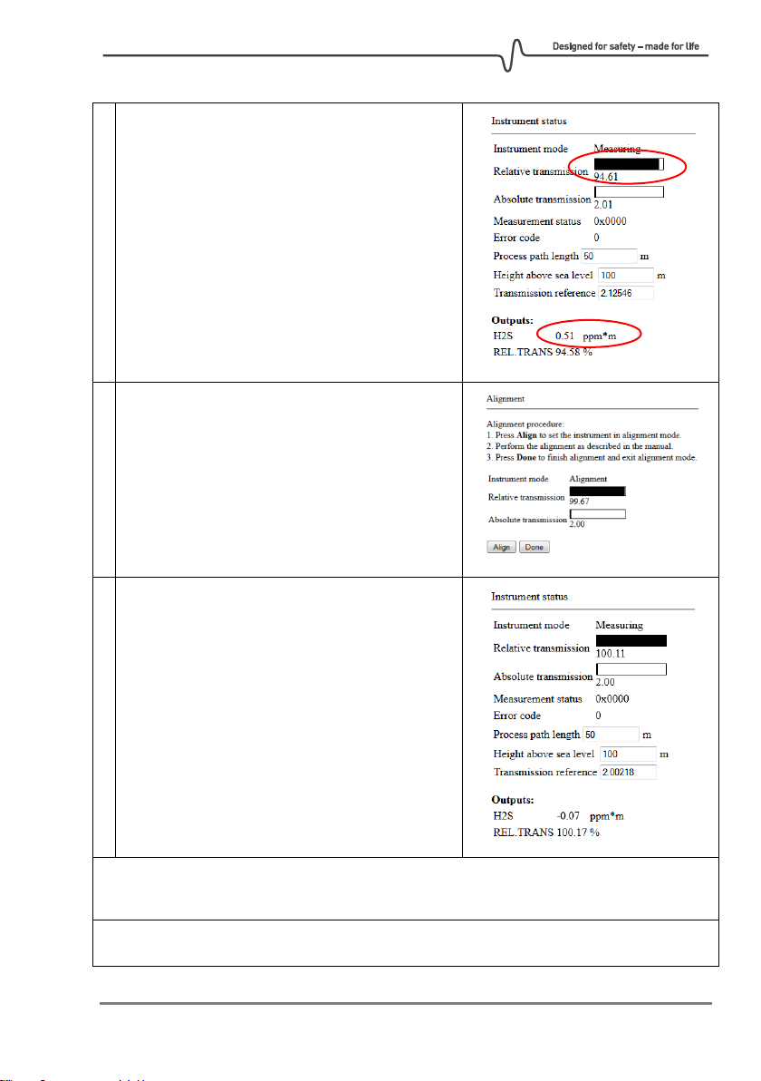
21
If the signal in step 20 was too noisy (outside ± 8
ppm*m), adjust slightly vertical or horizontal
alignment until the noise is reduced to an
acceptable level. Avoid reducing the signal
strength too much; a drop of 5 % in relative
transmission is fine.
22
When finished minimizing the noise, enter
Alignment mode, click "Done" and "Save" on the
following screen.
23
Verify that the GD1 enters Measuring mode.
Note! As a default the zero filter is activated, filtering any noise/measurement and outputting
4 mA on the analogue output as long as the measurement is below 7% FS.
Fine tuning finished!
Page 30
GD1 Page 30 of 76 850-816926-EN R06
3.3.2. Using a HART® for tuning of signal strength
For tuning of signal strength and setting of transmission reference level, use the Alignment
Interface Unit and a HART® terminal.
#
Step description
Illustration / response
1
Clean the lenses of both transmitter (TX) and
receiver (RX) for any dirt before proceeding.
The optical path should be clear at the time
of aligning (avoid fog, mist, steam, rain,
snow, etc.).
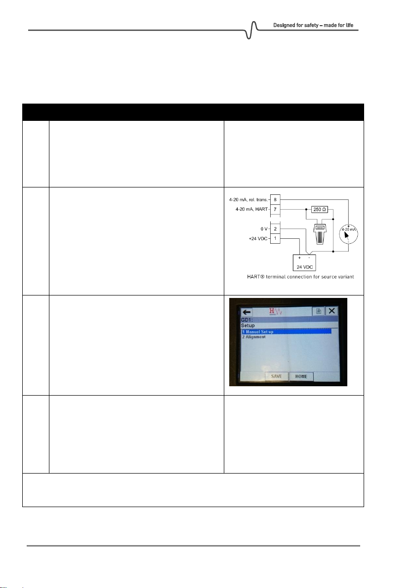
2
Connect the HART® terminal between
terminal 7 and 2, in parallel with a resistor as
shown in the figure to the right.
See section 0 for a more detailed description
on HART®.
3
On the HART® terminal start the “Alignment
procedure”. This can be found in the
following path:
ConfigurationSetupAlignment
4
On the HART® terminal enter the command:
#SM
Terminal response:
SM
Analogue loop 1 (terminal 7) and
loop 2 (terminal 8) will output
2 mA.
The system is now entering Service Mode. Using HART®, it is necessary to go through
Service Mode to enter or exit Alignment Mode.
Page 31
GD1 Page 31 of 76 850-816926-EN R06
5
On the HART® terminal enter the command:
#AM
Terminal response:
AM
Response on secondary loop (terminal
8) is set to between 3 and 14 mA
depending on the strength of the
optical signal received on the RX.
The system is now entering Alignment Mode (AM). If sufficient initial IR laser light is
collected by the receiver, the mA meter will show a value near 14 mA. If too little laser light
is received at the RX, the meter will show 3 mA. If this is the case, repeat coarse alignment
until the mA meter shows a higher value.
By factory setting, 14mA represent the strongest optical signal received after entering AM.
Any value lower than 14 mA means that the alignment between TX and RX is less optimized
than the best position seen during AM. If the alignment is improved the signal strength is
increasing and the value on the mA-meter will increase. If the signal strength is increased
to above 14 mA, the scale will automatically be increased so the new best position again is
14 mA. By outputting this information it allows for a user to gradually narrow down to an
optimal alignment position by manually sweeping the beam spot back and forth in each
direction.
6
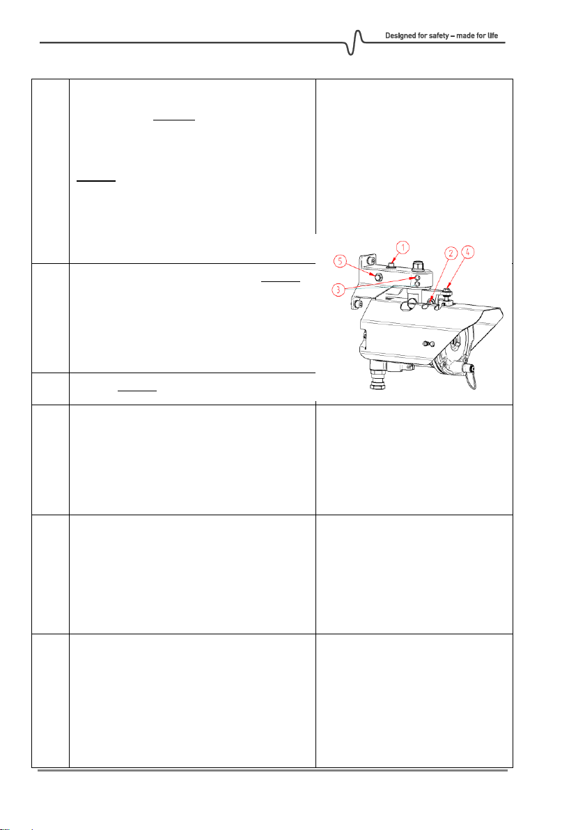
Slightly loosen screw 1 just enough for the
alignment mechanism to be able to move in
the horizontal direction.
7
Align in horizontal direction by turning screw
5. Turn very slowly in the direction whereby
the signal strength increases. The signal
reading will stay close to 14 mA as long as
the signal strength is increasing.
8
When the maximum signal strength is
reached and the mA reading will start to
drop.
9
Turn screw 5 back the other direction until
the signal strength is back at maximum. The
typical signal strength after a successful fine
alignment should preferably be above 13.9
mA. Do not expect to see exactly 14 mA.
10
Tighten screw 1.
Page 32
GD1 Page 32 of 76 850-816926-EN R06
11
Slightly loosen screw 2 just enough for the
alignment mechanism to be able to move in
the vertical direction. Note that the signal
strength will typically drop slightly when
screw 2 is loosened. If the value drops
significantly, it can be helpful to reset the
maximum recorded signal strength by
entering #AM on the HART® terminal.
12
Align in vertical direction by turning screw 4.
As for the horizontal alignment, turn very
slowly in the direction whereby the signal
increases. After reaching the maximum and
the signal starts to drop turn back until the
signal is back close to the maximum.
13
Tighten screw 2.
14
Store the current signal strength (absolute
transmission) and exit Alignment mode by
entering the following command in the
HART® terminal:
#SAV
Terminal response:
SM:OK
Saves the current settings, exits
Alignment Mode and enters
Service mode.
15
Set the elevation above sea level by entering:
#MW 0 <altitude in meters>
For example, for a setting of 100 meters
above sea level, the syntax is: #MW 0 100
Note! The height should be in whole meters.
Terminal response for the left
example:
REGISTER 0(ALTITUDE)=100
The accuracy of the height should
be better than ±350 meters.
16
Set the distance between the TX and RX by
entering the following command:
#MW 1 <path length>
For example, for a 15 meter path, the syntax
is: #MW 1 15
Note! The length should be in whole meters.
Terminal response:
REGISTER 1(PATH_LENGTH)=15
Page 33
GD1 Page 33 of 76 850-816926-EN R06
17
Check the current stored signal strength
(absolute transmission) by entering the
command:
#MR 5
Terminal response:
REGISTER
5(ABS_TRANS)=[absolute
transmission]
18
Store the current signal strength (optimum
alignment) to the transmission reference by
entering the following command:
#MW 2 <absolute transmission>
Use the <absolute transmission> value
received in the step above.
Terminal response:
REGISTER
2(TRANS_REF)=[transmission
reference]
Check that the absolute transmission is as expected (indicated in the graph below). The
obtained absolute transmission can vary somewhat from detector to detector. If the signal is
significantly lower than the suggested values, this is an indication that the fine alignment
needs to be improved, the RX is poorly aligned or the lenses are dirty. The RX is usually well
enough aligned during the Coarse alignment, but this can also be a reason for too low signal.
Page 34

GD1 Page 34 of 76 850-816926-EN R06
19
Save the alignment settings to the system by
entering the following command
#SAV
Terminal response:
IM:OK
This saves the current settings,
exits Service Mode and initialize
(reboots) the system.
Note! After initializing has completed the GD1 will enter Measuring Mode (normal
operational mode). The initialization can take up to 5 minutes.
Note! As a default the zero filter is activated. The zero filter removes any fluctuations below
14 ppm*m (7% FS). So the analogue output will show 4 mA as long as the measurement is
below 14 ppm*m.
Fine tuning finished!
Page 35
GD1 Page 35 of 76 850-816926-EN R06
3.4. Function test
Warning! During the test, the GD1 4 – 20 mA output going to control system will
be indicating gas when performing the procedure below.
Note! To conform with the SIL 2 Safety Integrity Level certification, a yearly
functional test is required..
#
Step description
Illustration / response
1
Clean the lenses on the TX and RX as described in
section 5.2.
2
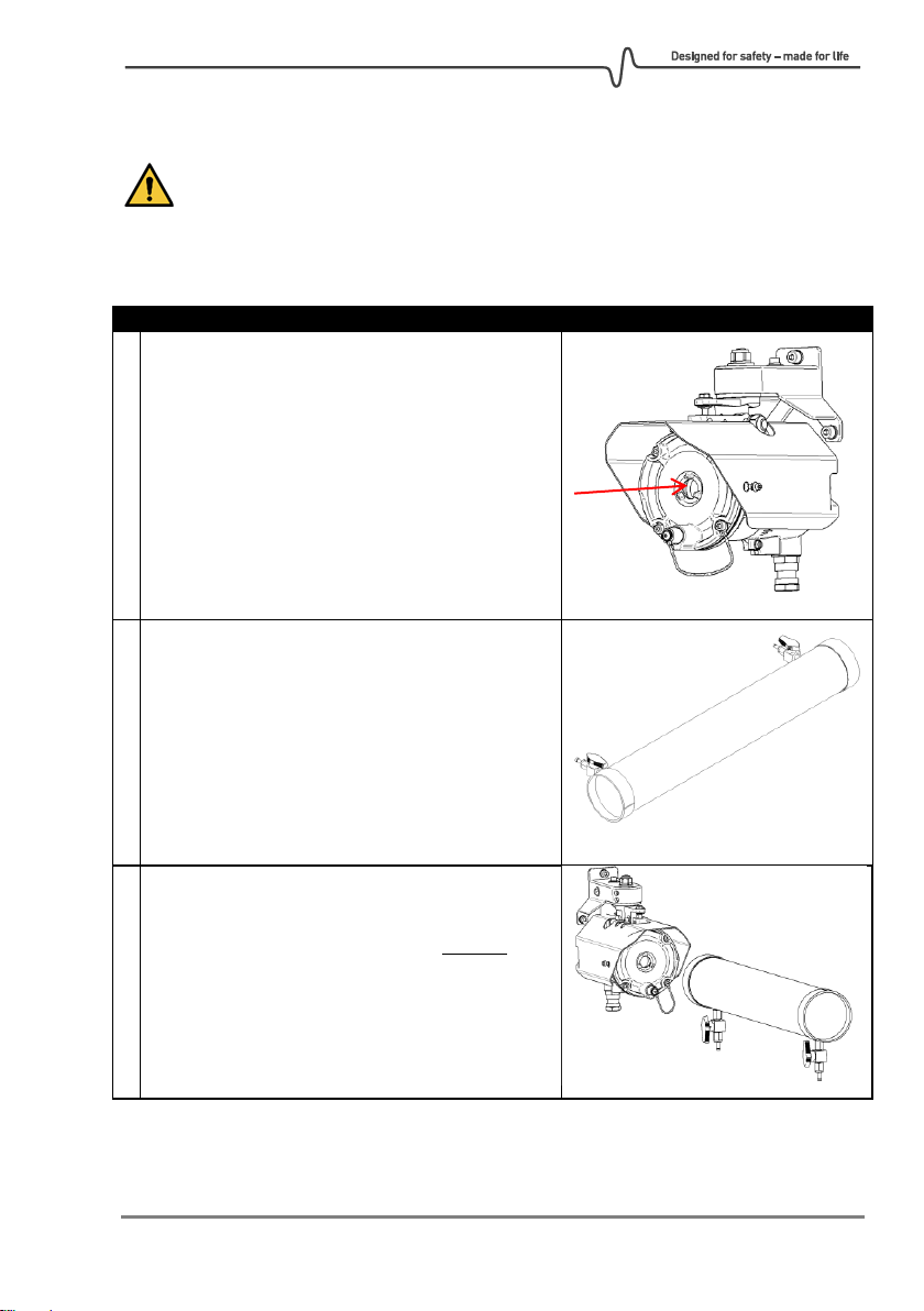
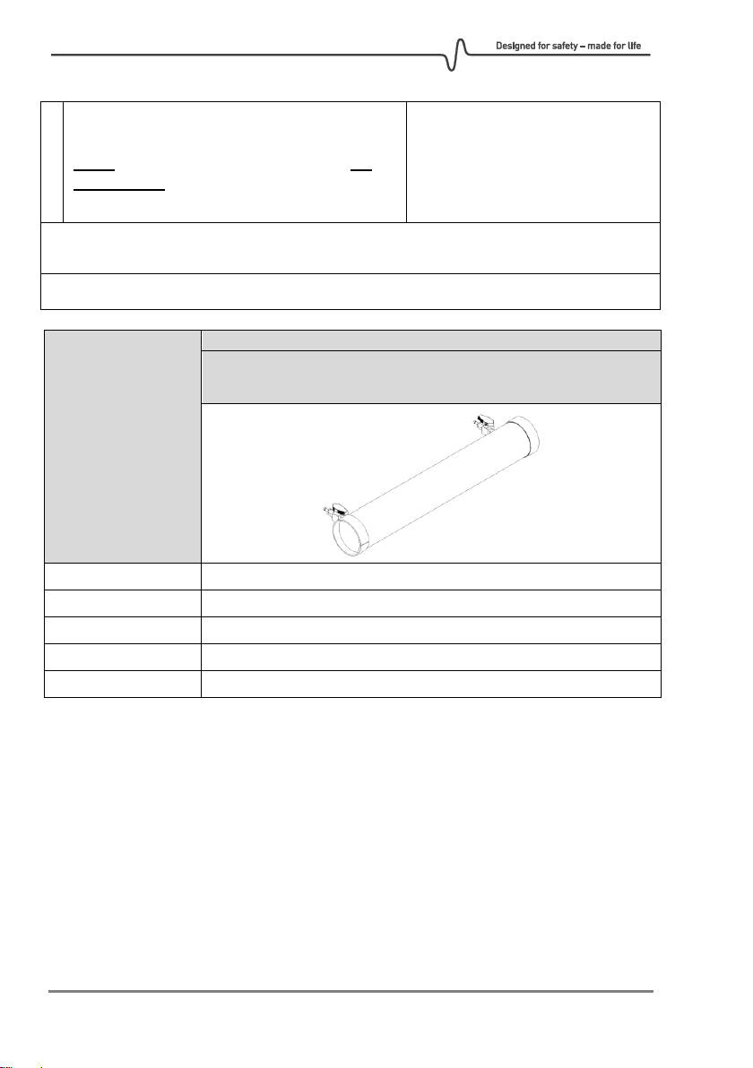
Fill the Test Cell as described in the section 4.2.
3
Position the Test Cell in front of the receiver (RX)
as indicated in the figure.
Page 36
GD1 Page 36 of 76 850-816926-EN R06
4
Verify the 4 – 20 mA output.
The output should change according to the
length of the Test Cell multiplied with the gas
concentration. The table below contain some
typical values
Expected output value (ppm*m):
<length> * <concentration>
Note! Depending on the precision of the gas mix inside the Test Cell, do not expect to see
an exact 1:1 response compared to the test gas concentration.
Functional test finished!
Gas concentration
(ppm)
Expected response
Test Cell (length 0.54 m)
(ppm*m)1
50
27
100
54
185
100 (50% full scale)2
300
162
690
373 (out of default range)
1. The expected response on the GD1 can be calculated from the following formula:
Response_GD1 = length_test_cell (meters) * gas_concentration (ppm) + noise
where the noise normally varies at less than ± 8 ppm*m.
2. ** A test gas with approximate 50% full scale response is good practice.
3.4.1. Performing function test with CO
2
as a non-toxic alternative
As a non-toxic alternative to using H2S for the functional test, the GD1 is also set up to look
for a peak in the CO2 wavelength. This response however, is only available using a Web
terminal through the service interface. The CO2 measurement is not available on the 4-20
mA analogue output.
Page 37
GD1 Page 37 of 76 850-816926-EN R06
#
Step description
Illustration / response
1
Clean the lenses on the TX and RX as described in
section 5.2.
2
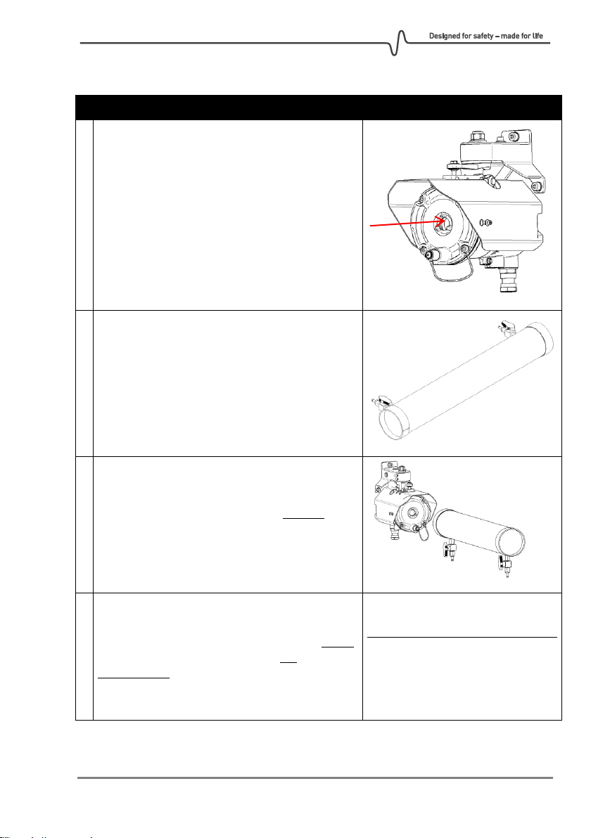
Fill the Test Cell with CO2 as described in the
section 4.2, but with CO2 instead of H2S.
Recommended CO2 test gas concentration is 10
000 – 100 000 ppm (1 %vol - 10 %vol).
3
Position the Test Cell in front of the receiver (RX)
as indicated in the figure.
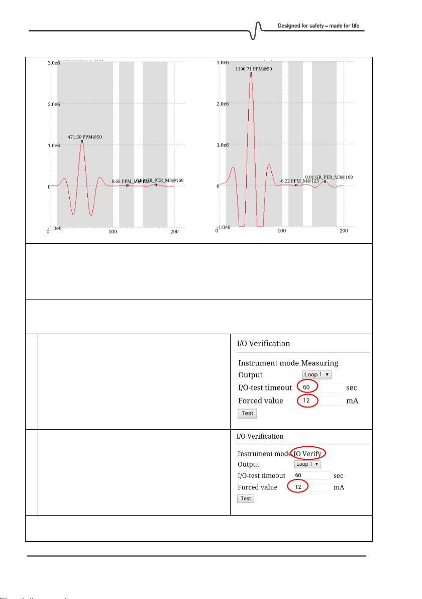
4
Verify the response in the GD1 spectrum.
The output should change according to the length
of the Test Cell multiplied with the gas
concentration. Below is an example with 40000
ppm CO2 filled into the Test Cell by breath.
Expected output value (ppm CO2):
𝑪
𝒄𝒆𝒍𝒍
∗ 𝟎. 𝟓𝟒 + 𝑪
𝒂𝒊𝒓
∗ 𝑷𝒂𝒕𝒉_𝒍𝒆𝒏𝒈𝒕𝒉
𝑷𝒂𝒕𝒉_𝒍𝒆𝒏𝒈𝒕𝒉
Where C
cell
and C
air
is the CO2
concentration in respectively the
Test Cell and air.
Page 38
GD1 Page 38 of 76 850-816926-EN R06
The above spectrum is found in GD1 Web interface. Spectrum to the left showing
472 ppm of CO2 in the air. To the right a spectrum showing 1 191 ppm as a result of
introducing the Test Cell filled with 40 000 ppm CO2.The value can be verified by using the
formula in step 4.
Note! Depending on the precision of the gas mix inside the Test Cell, do not expect to see an
exact 1:1 response compared to the test gas concentration.
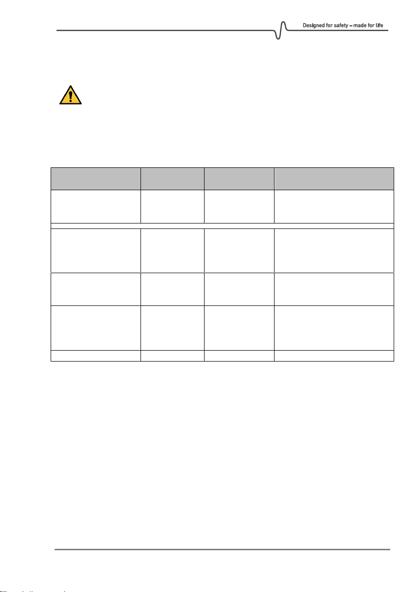
5
Run loop testing in the Web interface "I/O
verification" screen.
Recommend to use 60 sec test time.
Enter test value. For example 12 mA is 50% of full
scale.
6
After the GD1 goes into "IO Verify" mode, verify
that the analogue output matches the test value.
Functional test with CO2 finished!
Page 39
GD1 Page 39 of 76 850-816926-EN R06
4. OPERATION
The GD1 has no user adjustable parts inside. Do not open the GD1 housing, as
this will change the internal atmosphere, and the initial calibration could be
affected. Opening the GD1 also voids all warranty offered at the time of sale
The GD1 has no user controls or adjustments (except for the specified HART® settings). Gas
reading and fault signaling is given through the 4-20 mA current loop interface.
4.1. Analogue Output Protocol
Condition
Analogue
output 11
Analogue
output 22
Comment
Normal gas reading3
4 - 20 mA
0 – 14 mA
4 mA = 0% full scale
20 mA = 100% full scale and
higher
Early Dirty Optics
Warning
(90% signal
reduction)
3 mA
2 - 10 %
Detector will still output gas
concentration if reading is >
10 % full scale.
Beam block,
Alignment mode or
Service mode
2 mA
0 - 2 %
Default 60 sec delay before
entering beam block.
No gas detection.
Fault
or
Init mode (booting
up)
1 mA
Err
No gas detection.
No power
< 0.5 mA
Err
No gas detection.
1. The gas reading is clipped at 3.75 mA and 20 mA and will not go outside this range as
long as the GD1 is in Measurement mode.
2. Relative transmission.
3. As a default the zero filter is activated. The zero filter removes any fluctuations below
10 %FS. So the analogue output will show 4 mA as long as the measurement is below
10 %FS.
Page 40
GD1 Page 40 of 76 850-816926-EN R06
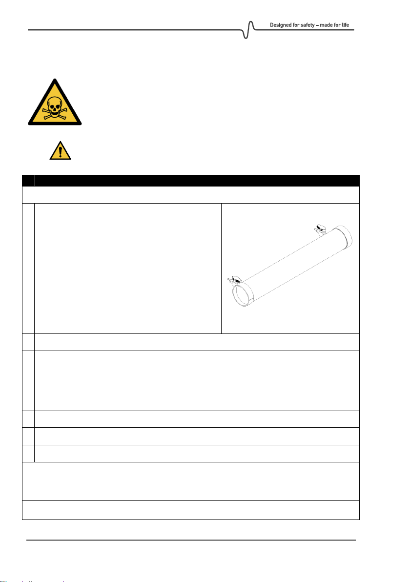
4.2. Test Cell filling and emptying instructions
When working with Hydrogen Sulphide (H2S) gas, observe the following:
• H
2
S is very toxic by inhalation
• Handle and use only in a well-ventilated space
• In case of accident or if you feel unwell, seek medical advice
immediately.
Read and understand the filling and discharging instructions before using
the Test Cell
#
Step description
Illustration / response
Note! Maximum allowed overpressure is 100 mbar.
1
Fit a filler hose from the H2S gas cylinder to one
of the valves on the Test Cell. Gas from gas
cylinder must be run through an mbar pressure
regulator regulating the pressure down to less
than 1 barg.
Fit an exhaust hose to the other valve. Exhaust
must be released to a safe area or into a suitable
ventilator system.
Dimension of the valve nozzles are 6.4 mm (1/4")
OD.
2
Open both valves on the Test Cell.
3
Start the filling of H2S from the gas bottle to the Test Cell. With a gas flow of 3
liter/minute, wait for approximate 2 minutes. For a lower gas flow filling time has to be
increased accordingly. For example for a flow of 1 liter/minute a filling time of 6
minutes is required. Too short filling time will result in the gas reading being lower
when performing Function test.
4
Close the gas bottle.
5
When the gas stops flowing, quickly close both valves on the Test Cell.
6
Disconnect the Test Cell from the hoses.
Note! After filling, the Test Cell will only be able to hold the gas at a reliable concentration
for a limited amount of time (few days). Replenish or refill the cell if the concentration is
suspected to have dropped.
Filling of Test Cell finished!
Page 41

GD1 Page 41 of 76 850-816926-EN R06
5. MAINTENANCE
5.1. Regular maintenance
The detector does not have any internal functions that require regular monitoring or
maintenance. Regular maintenance consists only of cleaning the optics.
The GD1 has no user adjustable parts. Do not open the GD1. Opening the GD1 voids all
warranty offered at the time of sale. The manufacturer shall do all repairs. Please refer to
the general warnings in chapter 7.
5.2. Cleaning of optical surfaces
Take care not to scratch the lenses and optical coating while cleaning.
1) First remove dust, sand, or other hard minerals using a soft brush or cloth, bulb
blower or dry and clean compressed gas or air. If using a compressed air gun or a
cloth, use it very lightly.
2) Spray the lens with a dilute solution of mild (dishwasher) detergent and water. It is a
good idea to first spray richly and let the cleaner dissolve some dirt and let it drip off
naturally. Repeat if necessary. If the dirt is still sticking a stronger solvent might be
required, a 1:1 mix of isopropyl alcohol and water can be used.
3) Wipe the lens lightly and carefully with a clean microfiber cloth or a lens cloth,
repeating step 2) and 3) until the surface is clean. Cotton swabs / Q-tips can be used
as an alternative.
4) Rinse with water and wipe dry.
5) Do not touch the lenses with your fingers.
Page 42

GD1 Page 42 of 76 850-816926-EN R06
THIS PAGE LEFT INTENTIONALLY BLANK
Page 43
GD1 Page 43 of 76 850-816926-EN R06
6. TROUBLESHOOTING
Simtronics shall do all service and repairs. Troubleshooting ashould be performed by the
used as described below.
The detector can also give fault messages if the mounting brackets are not sufficiently
stable over time, for example with temperature changes or passing trucks resulting in the
GD1 coming temporarily out of alignment. Before troubleshooting is commenced the
rigidity of the mounting structure should be checked.
The most common issues are the following:
• Misinterpretation of ppm*m as ppm. Described in section 10.4.
• Poor alignment. Please be aware that it is the absolute transmission that should be
optimized, not the relative transmission (section 3.3).
• Interference from a second transmitter as described in section 6.3.
Troubleshooting should always start by inspecting the detector’s lenses for contamination
and/or defects. The following list may be helpful:
Issue
Possible source of
problem
Suggested correction
Clean optics
warning
(3 mA)
Dirt on lens.
Clean optics (see section 5.2).
Detector out of
alignment.
Realign detector (see chapter 0).
Beam block
(2 mA)
Dirt on lens.
Clean optics (see section 5.2).
Detector out of
alignment.
Realign detector (see chapter 0).
Objects that block the
measuring path.
Remove objects that block.
Detector in alignment
or service mode
Reboot detector by Service Interface
(Ethernet), HART®, or by
cutting/reconnecting power.
Fault
(1 mA)
Check error code in
the Service interface
Status screen.
See section 0 for a description and
suggestion on how to solve the issue.
No Power
(0 mA)
No power to the
detector.
Verify with multi meter in the Junction box
that detector has power.
Check both detector and system cable
wires on terminal 1 and 2 in the junction
box.
No wireless or
cable Ethernet
connection
Not connected to
network
Make sure your browser is connected to
the GD1 wireless network.
Loose connector
Check that the terminal adapter is securely
connected to terminals 3 – 6
Page 44

GD1 Page 44 of 76 850-816926-EN R06
Loose wire in Junction
Box
Check terminals 3 – 6. Unscrew each wire,
both internal and external wiring to the
terminals, and ensure wires are properly
connected to the terminals.
No Ethernet cable
connection
Fault on cable
Check cable.
Device not set up to
connect to fixed IP
address
Configure laptop network settings to
connect using static IP.
Fault in detector
Contact Simtronics.
Fluctuating H2S
level
Noisy signal
Tune alignment as described in section 0.
Interfering detector
See section 6.3.
Other error
Check error code in
the Web Service or by
HART®.
See section 0 for a description and
suggestion on how to solve the issue.
Note! After solving an issue the Error code
might still be displayed for some time.
Absolute
transmission not
as high as
expected during
alignment
Dirty optics
Clean optics
Alignment of TX not
optimum
Perform tuning of TX as described in
section 3.3.
Alignment of RX not
optimum
Perform tuning of RX with the same
method as for TX described in section 3.3.
Laser beam
obstructed by an
object
Move the obstructing object or the GD1.
Page 45

GD1 Page 45 of 76 850-816926-EN R06
6.1. Error codes
Error codes are obtained by entering the Status screen through the Service Interface. After
an error has been corrected, it can still be displayed in the Status screen in the Service
interface.
Error #
Description
Action
1-4
Only relevant for vendor.
Contact Simtronics.
5
Issue with communication between TX
and RX.
Check wiring. See actions on
error 22.
6-7
Only relevant for vendor.
Contact Simtronics.
8
Issue booting up the receiver.
Check wiring. See actions on
error 22.
9-13
Only relevant for vendor.
Contact Simtronics.
14
Beam block. Possibly laser from TX is
obstructed by an object or alignment
need to be improved.
Remove blocking object or
improve alignment.
15
High transmission. Relative transmission
>125%.
Redo alignment. Make sure
lenses are clean before aligning
16
Timeout. Initialization took too long time.
Reboot the detector. Contact
Simtronics if Error persists.
17
Unable to track the CO2 line
Too short path length. Distance
between TX and RX shall be 5
meters or more.
Not able to find the CO line during CO
verification.
Contact Simtronics.
18-21
Hardware error.
Contact Simtronics.
22
No contact with RX. Possible poor
electrical connection in the Junction Box
or no power at RX.
Check power on RX.
Check wiring on terminals 1, 2,
11, 12 in both TX an RX
Junction Box.
23-31
Hardware error.
Contact Simtronics.
32
Laser temperature too high. The detector
might be too hot for the laser to start up.
Disconnect power, cool down
the detector and reboot.
33-40
Software error.
Restart the detector by turning
power off and on again.
If problem persists please
contact Simtronics.
Page 46
GD1 Page 46 of 76 850-816926-EN R06
6.2. Tuning detector for less noise
It is normal to see fluctuations of the H2S signal below ± 8 ppm*m. This is due to noise in
the measurement. Several effects can influence the noise in the H2S measurement such as:
Alignment between RX and TX, dirt on lenses, rain, sandstorm, snow, reflections and
interference from other detectors. The interference from another detector will typically be
observed as sudden high values of H2S, and is described in section 6.3.
To tune for less noise on the GD1 the alignment can be adjusted slightly, as described in
the procedure below:
#
Step description
Illustration
1
Clean the lenses of both transmitter (TX) and
receiver (RX) for any dirt before proceeding.
The optical path should be clear at the time of
aligning (avoid fog, mist, steam, rain, snow,
etc.).
2
Log into the service interface with Ethernet
connection or HART®.
3
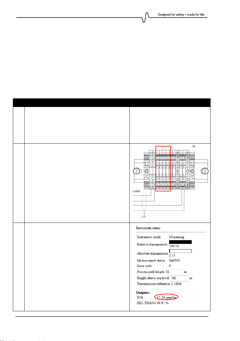
Observe H2S level and signal strength on the
Web Interface Status screen, or with a mAmeter on terminal 7 (H2S signal) and 8 (signal
strength). It is normal for the H2S signal to
fluctuate up to ± 8 ppm*m.
Page 47
GD1 Page 47 of 76 850-816926-EN R06
4
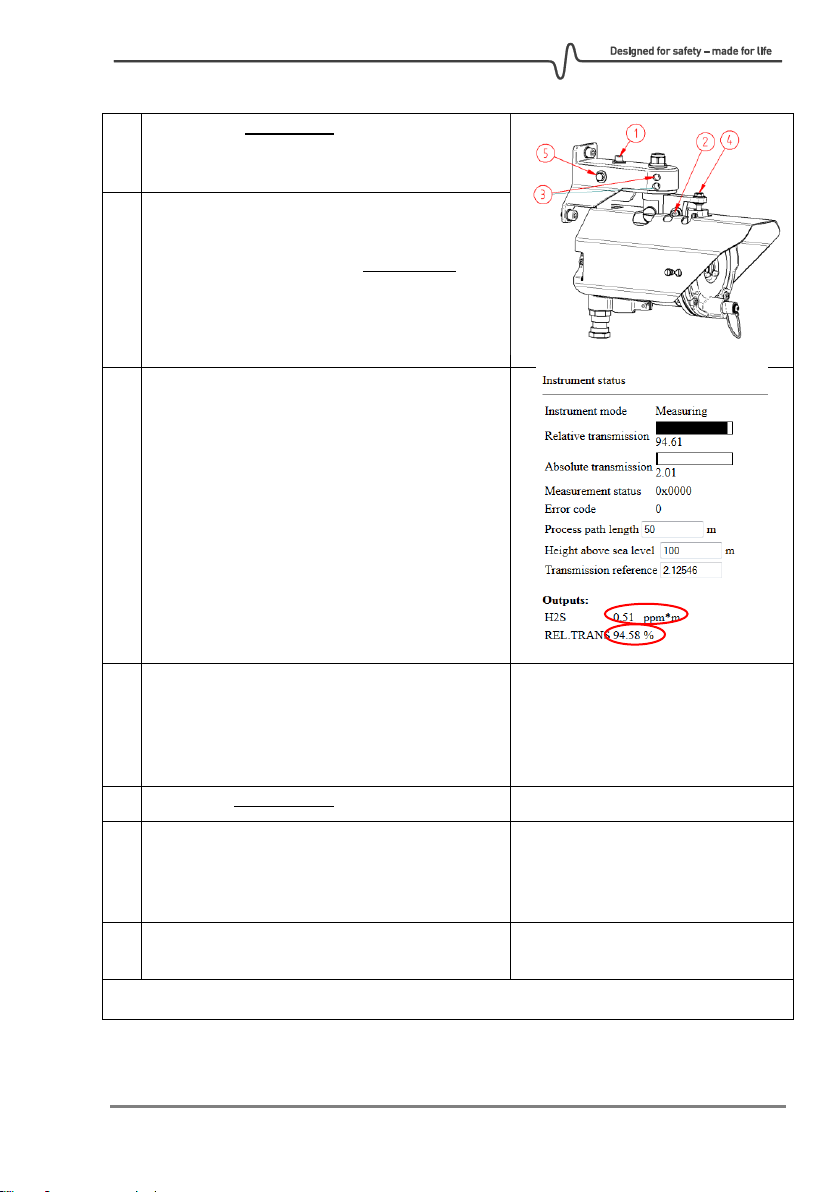
Loosen only screw 1 or 2 for adjustment in
respectively the horizontal (screw 5) or vertical
(screw 4) direction.
5
Adjust detector slightly with screw 5 or 4 for
respectively horizontal or vertical direction.
6
Observe that H2S fluctuations stay within
± 8 ppm*m. It can take up to a minute for the
noise signal to stabilize. Preferably, the relative
transmission should not drop below 90%
during this tuning. If the signal is OK and
relative transmission did not drop too much,
continue to the step 9.
7
If the signal still needs tuning go back to step 6.
If it is not possible to get low fluctuations by
tuning in the current direction without going
below 90% relative transmission, go back to
step 5 and start adjusting in another direction.
8
Make sure screw 1 and 2 are tightened.
9
Go into the COMMISSIONING ALIGNMENT
screen and set the detector in "Alignment
mode". Then store the new relative
transmission by clicking DONE and SAVE.
10
Go to the Status screen to verify the detector is
in Measurement mode and noise level is OK.
Tuning noise finished!
Page 48
GD1 Page 48 of 76 850-816926-EN R06
6.3. Interference from another GD1
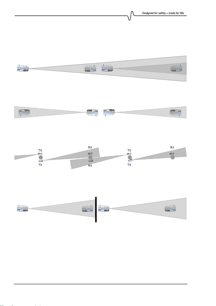
Interference from other detectors is observed as sudden very high values of H2S. This can
occur if the laser from more than one transmitter is picked up by the same receiver. In the
image below this effect is illustrated where two transmitters are emitting into one receiver.
Below is a simple solution to prevent interference from another transmitter. The position
of transmitter and receiver is swapped so the laser beams are going in opposite directions.
This solution will not work if there are many GD1's positioned in a line.
Below a second possible solution is illustrated. In this example several GD1's are positioned
so the laser beam does not affect other detectors.
If it is not possible to organize the detectors so they will not interfere, there is a third
solution as illustrated below. A sufficiently large physical barrier, here in form of a small
plate, between the GD1's so that they cannot interfere with each other.
NOTE: In some rare cases, even though the interfering transmitter is mounted behind the
receiver from the noisy detector, the laser can be reflected back into the detector by a
reflective surface (e.g. sign, structural plate metal).
6.4. Download the Diagnostics file
A diagnostics file is required when contacting Simtronics or its authorized distributors for
support. The diagnostics file contains information concerning serial number, the present
settings and errors in the instrument. Follow the instructions to download a diagnostics
file:
Page 49

GD1 Page 49 of 76 850-816926-EN R06
1. Connect to the GD1 with the Ethernet or wireless connection and use a Web
browser to log into the GD1 Service Interface on http://192.168.1.237 .
2. Enter the Diagnostics page.
3. Right Click "Download diagnostics file" and select "Save Target As…" or "Save Link
As", depending on what type of browser being used.
4. Store the file to a disc. In the file name please use the site detector ID tag number.
5. Click Done to return to main menu
6. Send the diagnostics file to SIMTRONICS support.
6.5. Uploading a Configuration file
Simtronics can create an encrypted settings file that on upload to the GD1 can change
critical detector settings. This can be used in situations where the customer requests a
settings change, for example changing the span of the detector. The file is encrypted to
avoid non authorized persons changing critical settings. It is important to ensure that the
Configuration file belongs to the actual instrument at hand. Follow the procedure below to
upload a settings file:
Note! It is recommended to back up the initial Configuration file, by downloading it from
the instrument. If needed, this file can later be used to reset the GD1 back to the original
state. The Configuration file is downloaded on the Diagnostics page in the Service
interface.
Page 50
GD1 Page 50 of 76 850-816926-EN R06
#
Step description
Illustration
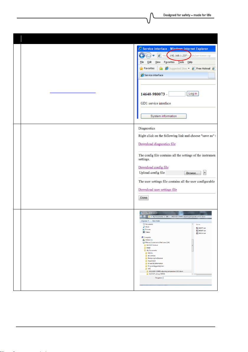
1
Connect to the GD1 Service Interface as
described in section 10.5.
IP address: http://192.168.1.237
2
Enter the Diagnostics page. Click "Download
config file" and store this in a safe place. This file
can be used later to go back to the original
settings if necessary.
3
Click "Browse" to find the new settings file.
Page 51
GD1 Page 51 of 76 850-816926-EN R06
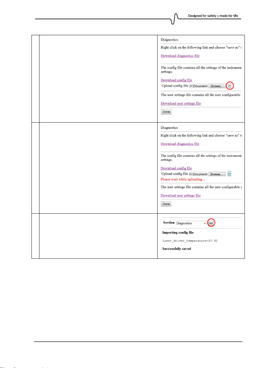
4
Click the arrow to start uploading the file to the
GD1.
5
The new settings are being uploaded.
6
When the uploading is finished, click "Go" to
return to the Diagnostics page.
Click "Done" on the Diagnostics page.
Page 52
GD1 Page 52 of 76 850-816926-EN R06
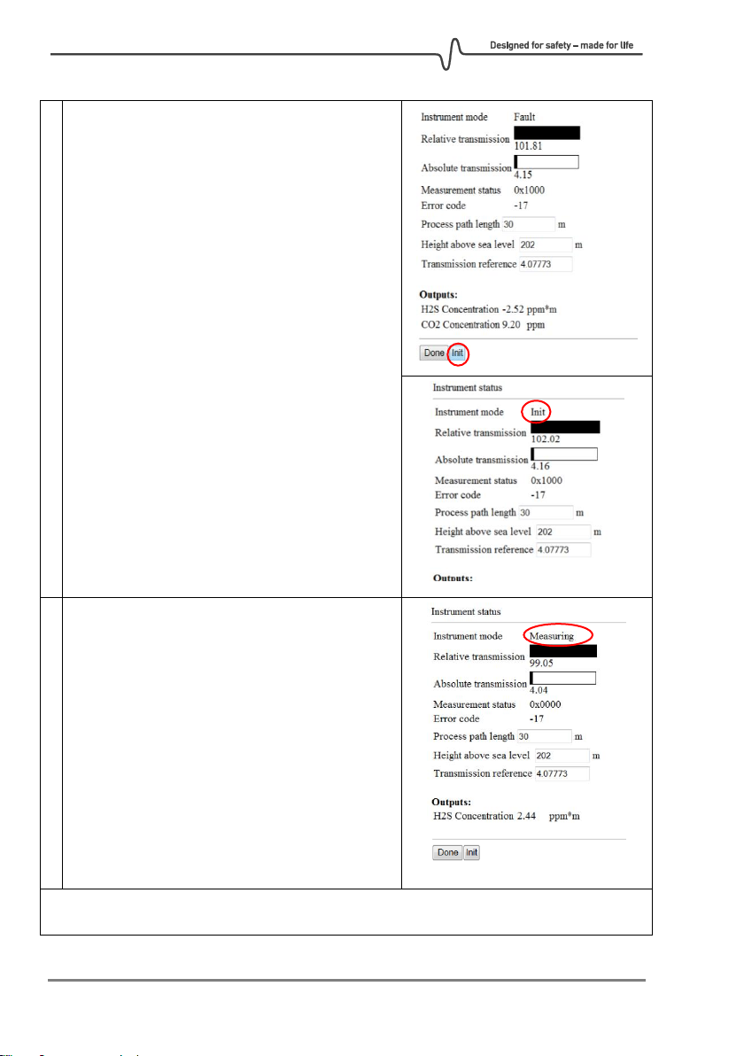
7
Click "Init" to restart the GD1 and initiate the
new settings.
8
After some time the GD1 should enter
Measuring mode.
Configuration upload finished!
Page 53
GD1 Page 53 of 76 850-816926-EN R06
7. CERTIFICATIONS AND STANDARDS
7.1. Certification
The GD1 has been certified according to ATEX Directive 2014/34/EU and IECEx scheme.
7.2. Marking
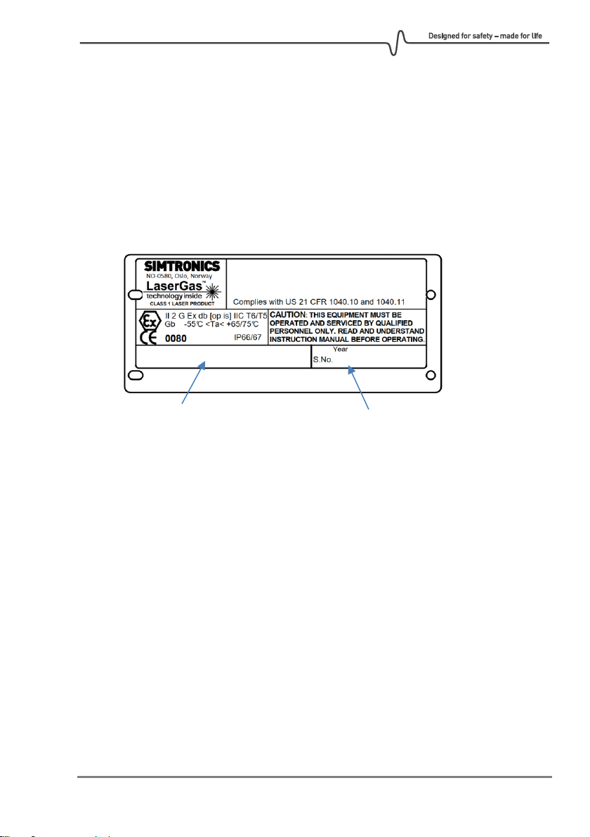
The GD1 product identification labels are shown in the figure below. The composition of
the labels is in accordance with ATEX Directive 2014/34/EU.
Instrument Part Number (P/N) Manufacturing Date and Serial Number (S/N)
NB! Please refer to full serial number (2+5 digits) for factory enquiries, service or support.
7.3. Specific condition for use in Explosive Atmosphere “X”
“X”- Flameproof joints have values different from those specified in the tables of standard
EN 60079-1. Simtronics does not allow repairs and disclaims any responsibility for material
modifications.
The threaded joints may be lubricated to maintain flameproof protection. Only nonhardening lubricants or non-corrosive agents having no volatile solvents may be used.
“X”-The fasteners used on the Ex-d enclosure must be of the type specified by the
manufacturer M6x10, yield stress min. 500MPa
“X”-The Cable gland may not provide sufficient clamping. User shall provide additional
clamping of the cable to ensure that pulling and twisting is not transmitted to the
terminations.
Presafe 17 ATEX 11275X
IECEx PRE 17.0057X
GD1-L0T-31KH-0XH-A3
18-nnnnn
Page 54

GD1 Page 54 of 76 850-816926-EN R06
THIS PAGE LEFT INTENTIONALLY BLANK
Page 55
GD1 Page 55 of 76 850-816926-EN R06
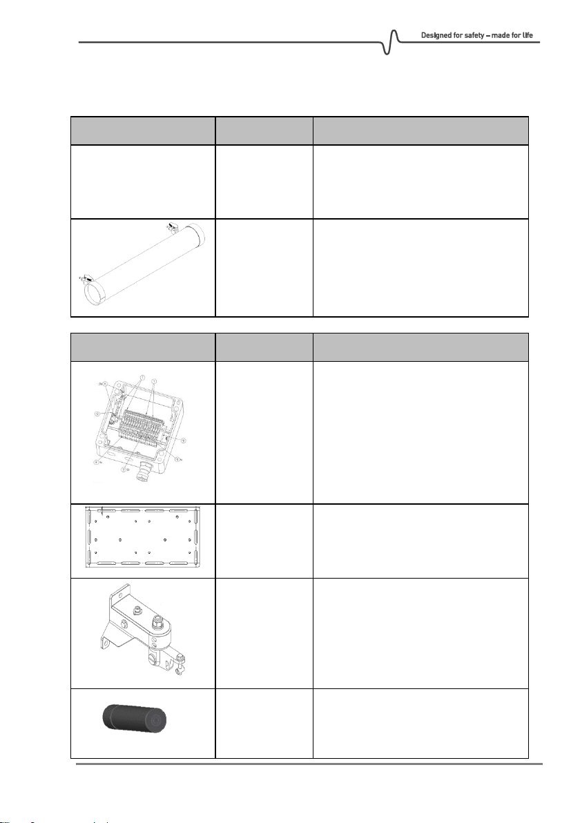
8. ACCESSORIES AND SPARE PARTS
Accessory
Part Number
Description
GD1-X00-TT06
Alignment Kit
Suitcase with Laser alignment tools,
Alignment Interface Unit and carry
case.
GD1-X00-TT05
Gas Test Cell Kit – long version
Airtight chamber for function and
calibration tests. The chamber has a
length of 54 cm.
Spare part
Part Number
Description
499-816526
Junction box
(temperature range -40 to +65℃)
GD1-X00-TB01
Mounting plate
499-816755
Adjustment bracket
245-906385
Alignment kit laser pointer
Page 56
GD1 Page 56 of 76 850-816926-EN R06
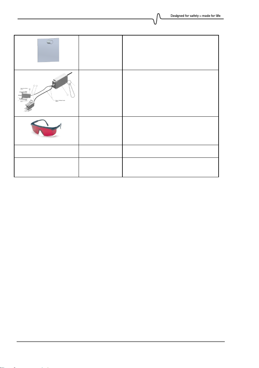
499-817033
Alignment kit reflector plate
499-816845
Wireless router
419-906123
Laser glasses
814-816855
Spare screws and nuts for the GD1.
700-816859
All typical tools needed for alignment
and service of the GD1.
Page 57
GD1 Page 57 of 76 850-816926-EN R06
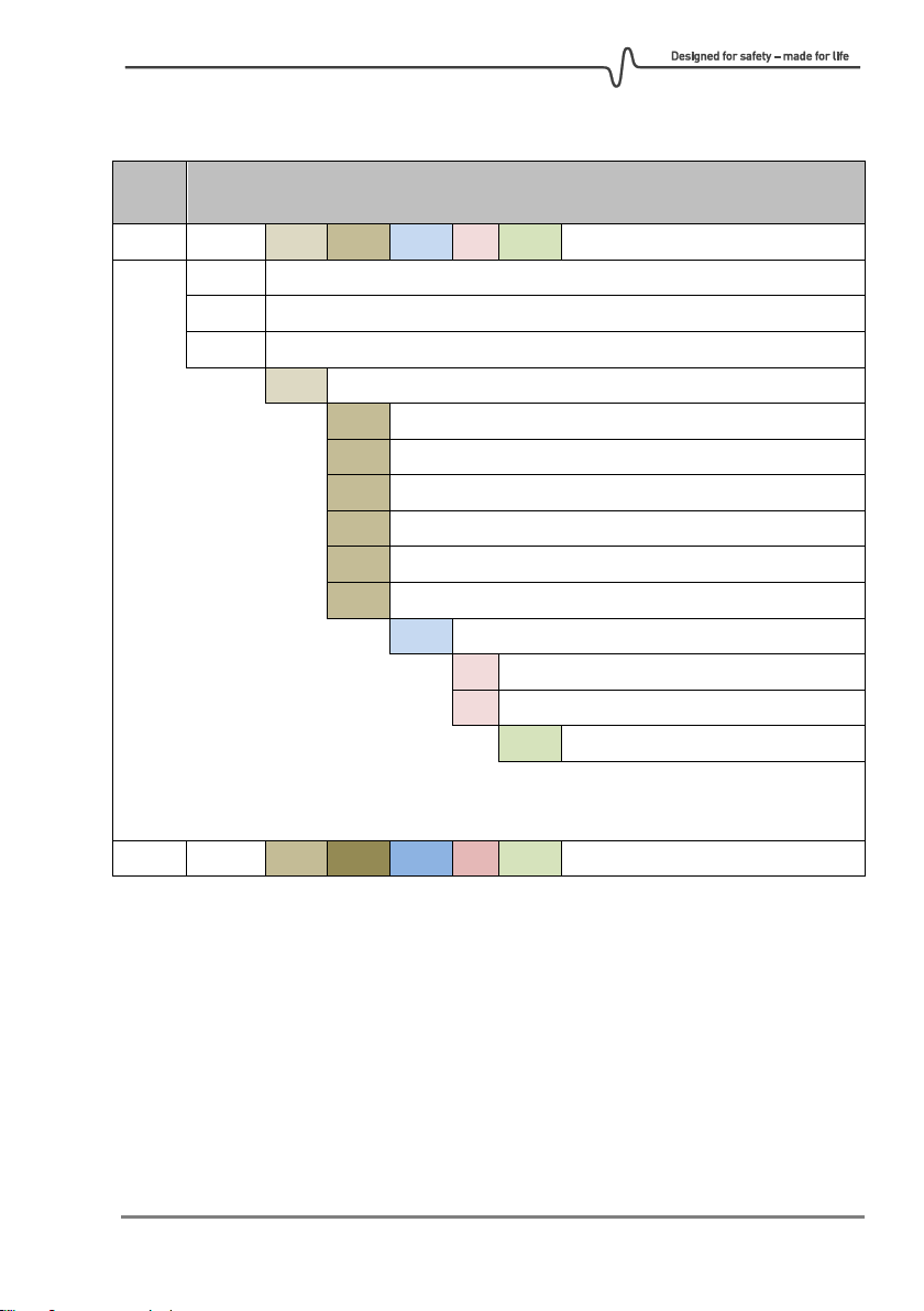
8.1. Ordering information for the GD1
Mode
l
Description
GD1
-L0*
-31
**
-0X * -A3 P
Transmitter and Receiver
T
Transmitter only
R
Receiver only
31
H2S
KH
0 – 200 ppm*m scale
KJ
0 – 500 ppm*m scale
KK
0 – 1 000 ppm*m scale
KL
0 – 2 000 ppm*m scale
KM
0 – 5 000 ppm*m scale
KN
0 – 10 000 ppm*m scale
0X
SS316 / ATEX
H
4-20 mA source interface + HART®
J
4-20 mA sink interface + HART®
A3
Mark III
GD1
-L0P
-31
KH
-0X H -A3
Typical Part Number
Page 58

GD1 Page 58 of 76 850-816926-EN R06
THIS PAGE LEFT INTENTIONALLY BLANK
Page 59

GD1 Page 59 of 76 850-816926-EN R06
9. TECHNICAL SPECIFICATIONS
GENERAL
Detection method Near IR laser scanning
IR-Source Tunable laser diode
Laser Class 1, eye safe
Detected gas H2S
Range 0 - 200 ppm*m (default)
Path length 5 - 75 m
Self-test Continuous
Calibration Factory set, no field recalibration
Safety Integrity Level 2 (Functional test interval of once per year)
PERFORMANCE
Accuracy < ±8 ppm*m (<±4% of full range)
Repeatability < ±8 ppm*m (<±4% of full range)
Response time 5 sec.
OPTICS
Alignment ±0.3°
Optics Heated (Transmitter and Receiver)
Obscuration >98% to signal Beam block (2 mA)
Optional: Warning (3 mA)
>90% to signal "Early clean optics"
OUTPUT SIGNAL
Standard 4-20 mA sink or source (factory set),
max. load impedance 500 ,
HART®
Fault signals Fault 1 mA
Beam block 2 mA
Option: Warning 3 mA
Zero filter The “Zero filter” is by default set to filter any
noise/measurement below 10 % Full Scale.
ELECTRICAL
Power supply 24 V DC nominal, range 18-32 V DC
Power consumption < 15 W (RX: <5W + TX: <10W)
Cable entry M25
System fuse Power to the GD1 shall be protected by 1A fuse
Page 60

GD1 Page 60 of 76 850-816926-EN R06
TEMPERATURE RANGE
Operating -55°C to + 65°C (-67°F to +149°F)
ATEX Flameproof -55°C to + 75°C (-67°F to +167°F)
IECEx Flameproof -55°C to + 75°C (-67°F to +167°F)
ENVIRONMENTAL
Ingress protection IP66 / IP67 IEC 60529
Humidity (operation) 0 – 100% RH
Humidity (storage) 0 – 95% RH
MECHANICAL
TX and RX Housing:
- Material Stainless steel (ASTM 316)
- Weight 6 Kg (12 lbs) (each)
- Dimensions Ref outline drawing
Junction Box:
- Material GRP
- Weight 2.0 Kg (4.4 lbs) (each)
- Dimensions Ref outline drawing
Total assembly weight 12 kg (26 lbs) (Tx or Rx + JB + bracket + plate)
OUTLINE DIMENSIONS
Page 61
GD1 Page 61 of 76 850-816926-EN R06
10. SYSTEM DESCRIPTION
The Simtronics GD1 sets a new standard for toxic gas detection. Using a tunable laser
diode, the GD1 delivers enhanced coverage and fail safe detection. The performance
improvement marks a major step for safety systems and life cycle cost savings.
The GD1 has been designed with features that provide an effective response to the
detection of gas hazards in a wide range of industrial environments from offshore
production facilities to wastewater treatment plants.
At the heart of the detector is a tunable laser diode that eliminates environmental effects
from sun, rain and fog. The laser scans single absorption lines where there is no crossinterference from other gases. The laser operates in the near infrared wavelength region,
and is invisible to the naked eye. The GD1 laser is eye safe, and does not present any
danger even if looked straight into.
Unlike traditional methods for detecting H2S, MOS or EC cell, the GD1 needs no
recalibration and can replace multiple standard detectors to cover the same potential leak
area.
The measurement technique used in the GD1 is intrinsically a baseline-free technique.
Therefore, a calibration of the zero level is never done. The complete optomechanical
design and construction is so stable that an ultra-fast speed of response can be achieved
whilst providing unparalleled service life and detector stability, thus saving on maintenance
and service costs.
10.1. System
The GD1 is an optical open path Gas Detector with a separate transmitter (TX) and receiver
(RX). The transmitter emits infrared laser light which is detected by the receiver. The
detection principle is based on measuring the absorption of light by the free gas molecules
present in the measuring path.
RECEIVER TRANSMITTER
In contrast to traditional hydrocarbon open path detectors which emit broad-banded light,
the GD1 uses a tunable diode laser (TDL) as its light source and emits light at a very narrow
bandwidth. This technology enables high-resolution spectroscopy and the ability to
Page 62

GD1 Page 62 of 76 850-816926-EN R06
measure absorption from single absorption lines, eliminating direct interference from
other gases and subsequent false gas alarms.
The laser diode has a very long service life and requires no recalibration or replacement.
The GD1 technology enables ultra-fast detection to single gas species at low
concentrations. The laser diode is tuned in wavelength and temperature to match the
absorption line to be measured. The laser is then scanned across the absorption line. The
line itself is carefully selected to ensure there is no interfering absorption in the scan area.
The GD1 continuously monitors the measuring path and the optical and electronic
functions. The detector will always show correct gas concentration as long as there are no
error messages.
The transmitter and receiver optics are heated to keep the optical surfaces free from dew,
snow and ice.
Maintenance will normally only consist of cleaning the optics. The detector gives an error
message if cleaning is required.
The GD1 offers digital communication capabilities along with standard 4-20 mA analogue
current loops, to aid installation, setup, configuration and servicing.
10.2. Application areas
Area monitoring of:
- Oil and gas installations onshore and offshore
- Petrochemical plants
- Chemical plants
- Refineries
- Pipelines
- Marine
- Waste disposal plants
- Process water facilities
- General industry
Page 63

GD1 Page 63 of 76 850-816926-EN R06
10.3. Positioning considerations
Open path detectors are more susceptible to external interference compared to point
detectors. To avoid performance reduction and downtime, the following should be taken
into consideration when choosing mounting location.
The detector should be attached to a mechanically rigid structure to help keep the unit in
alignment due to influences such as:
• Thermal movement due to the effects of the sun and temperature changes
• The effects of strong wind, vibration from equipment such as pumps, turbines and
cranes, high-pressure flushing of the detector etc.
• Other mechanical effects, particularly in high-traffic areas.
The measuring path should be horizontal to minimize environmental effects such as rain
and snow. Other factors to be taken into account could be temporary scaffolding, large
vehicles etc.
10.3.1. General positioning considerations regarding a gas cloud
The concentration of a gas cloud rapidly reduces as the distance from the leak source
increases. The detector should therefore be placed as close as possible to potential leakage
sources. Normally prevailing wind directions must be taken into account when positioning
the detector.
Positioning height of the detector should also be taken into consideration. H2S is heavier
than air and has a tendency to accumulate in low areas. Due to the H2S being heavier than
air the detector should normally be positioned at low heights.
In places where there can be thick fog or heavy snowdrifts it is recommended to keep the
measuring path as short as possible.
Even if GD1 is practically solar blind, positioning the measuring path in a North – South
direction is preferable to avoid direct sunlight.
The performance of an Open Path gas detector is influenced by:
• Distance from leak source
• Weather and environmental conditions
• Temporary or permanent path obstruction
• Leakage characteristic (pressure, size, fluid, temperature)
• Gas density (heavier or lighter than air)
• Vibration and stability of mounting structure
• Exhaust or steam discharges hitting the optics.
The detector should be placed according to a gas dispersion analysis taking into account all
the factors above.
Page 64
GD1 Page 64 of 76 850-816926-EN R06
10.4. Detection principles
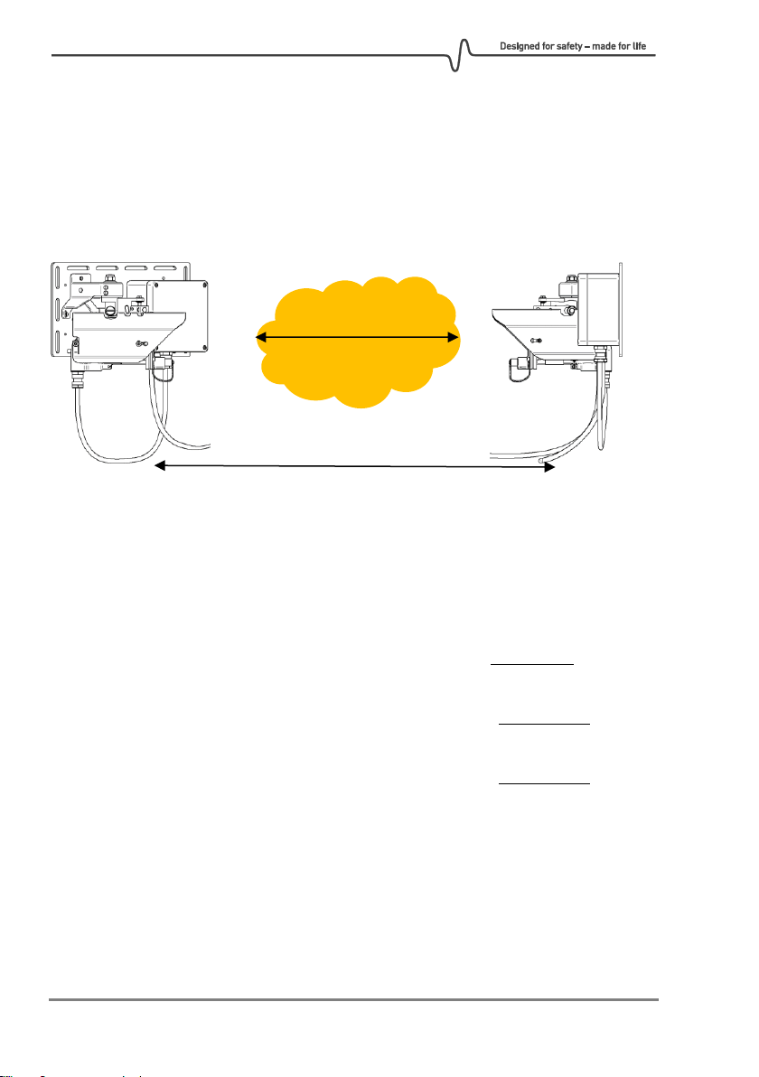
Unlike a point detector, the GD1 Open Path Detector will not measure the concentration of
the gas in the path between transmitter and receiver. The GD1 measures the total amount
of H2S in the path and the value returned by the GD1 is in ppm*m. Below are three
examples with calculations on what value is expected on the GD1 for different gas clouds.
The drawing above illustrates a GD1 positioned with a gas cloud from a H2S drifting into the
laser beam of the GD1. The average concentration of the gas cloud is C ppm H2S. The width
of the gas cloud is L meters where the beam is crossing. If the path length is smaller than
the gas cloud, the distance L will be equal to the path length. For the gas cloud in this
example, we would expect the following signals from the GD1:
Example 1 - gas cloud characteristics: C = 5 ppm; L = 15 meters
Expected measurement of the GD1 = C * L = 5 ppm * 15 m = 75 ppm*m
Example 2 - gas cloud characteristics: C = 10 ppm; L = 15 meters
Expected measurement of the GD1 = C * L = 10 ppm * 15 m = 150 ppm*m
Example 3 - gas cloud characteristics: C = 150 ppm; L = 1 meters
Expected measurement of the GD1 = C * L = 10 ppm * 15 m = 150 ppm*m
Observation 1! Same cloud size will give same measurement irrespective of path length
(this provided that the gas cloud is smaller than the path length).
Observation 2! If cloud size is known, the average cloud concentration can be calculated by
dividing the ppm*m measurement with path length. This can typically be done only if a
spreading analysis shows that the cloud always will cover the whole path length between
the TX and RX, for example if the GD1 is placed sufficiently far from the leak point.
Path length
Width of cloud: L meters
Page 65
GD1 Page 65 of 76 850-816926-EN R06
Observation 3! Example 3 shows that different cloud can give same measured value.
Therefore the GD1 is typically used as a “safe fence” around an installation to signal if there
is an abnormal and potentially unsafe situation, and not to measure the actual
concentration of the gas.
10.5. How to connect to the web interface with the Ethernet cable
In some circumstances it might be requested by the user to be able to connect with cable
and not the Wireless router. Below is a description on how to connect to the GD1 Service
Interface with a web browser:
Note! When connecting with the Ethernet cable, it is necessary to configure the network
interface card to static IP and the following settings:
IP address 192.168.1.236
Subnet mask 255.255.255.0
Default gateway 192.168.1.253
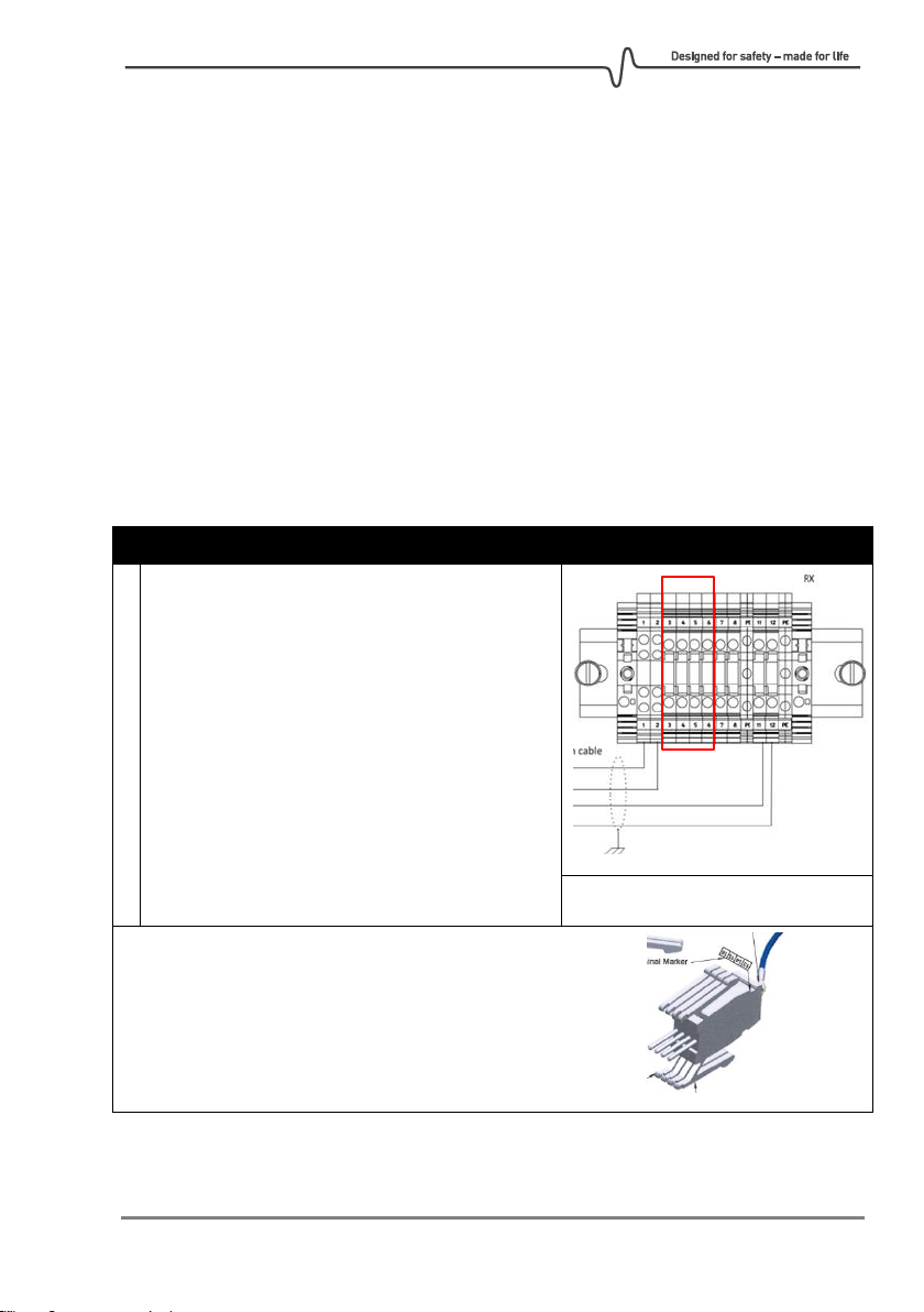
#
Step description
Illustration
1
On the transmitter, connect the Ethernet
adapter to the Junction Box terminals 3-6.
An image of the Ethernet adapter is displayed to the
right.
Page 66
GD1 Page 66 of 76 850-816926-EN R06
2
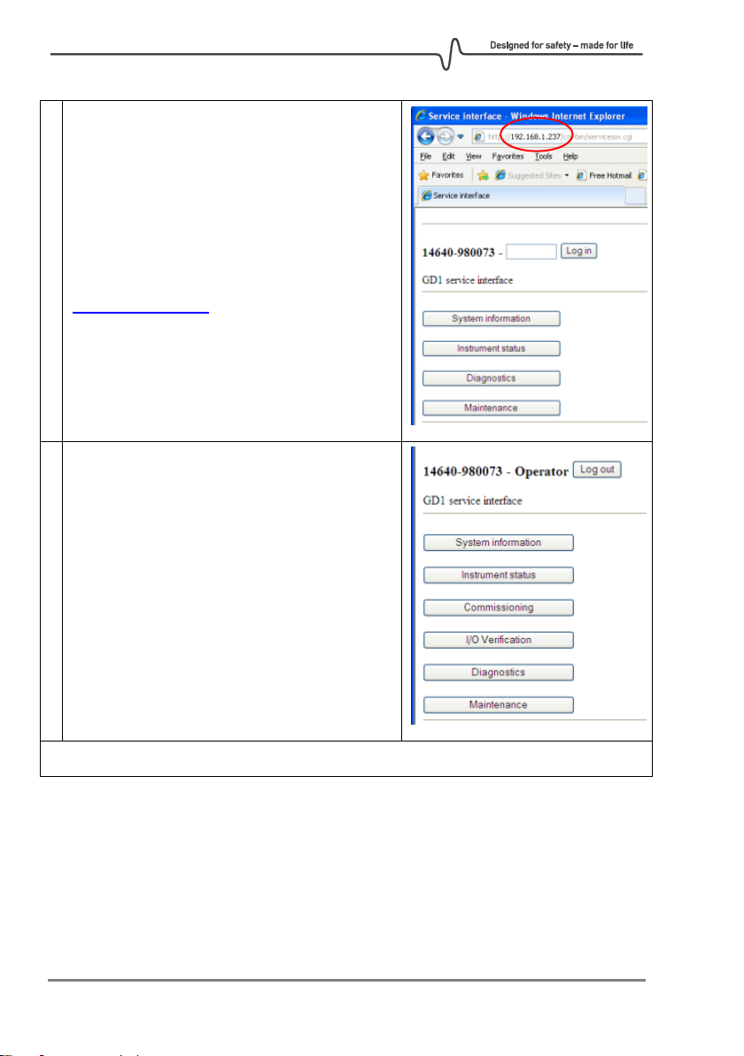
Select a device having Web browsing capabilities
with the wireless router or Ethernet cable. In the
web browser of the device, enter the GD1
Service Interface on the address
http://192.168.1.237
3
Log into the Service Interface with the Operator
password: "gd1tlc"
After logging in as Operator more functions are
accessible as illustrated in the image to the right.
Procedure finished!
Page 67
GD1 Page 67 of 76 850-816926-EN R06
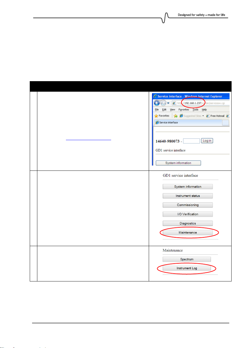
10.6. Data logging functionality
The GD1 has 24 MB of space reserved for storage of data chosen by the user. The user can
specify at what interval the data shall be recorded and stored. The data log can be
downloaded for review of for example gas releases recorded during the latest months. The
GD1 can typically store several years of data logging before it is starting to overwrite the
oldest data entries.
#
Step description data logging
Illustration
1
Connect to the GD1 Service Interface as
described in section 10.5.
IP address: http://192.168.1.237
2
Enter the “Maintenance” page.
3
Enter the “Instrument Log” page.
Page 68
GD1 Page 68 of 76 850-816926-EN R06
4
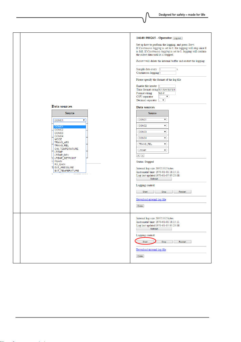
In the “Instrument Log” page the operator set up
what data should be logged and at what interval.
Up to six data variables can be logged and is
chosen from a drop-down menu as shown
below.
5
Click “Start” to start logging the selected
variables in the previous step.
Page 69
GD1 Page 69 of 76 850-816926-EN R06
6
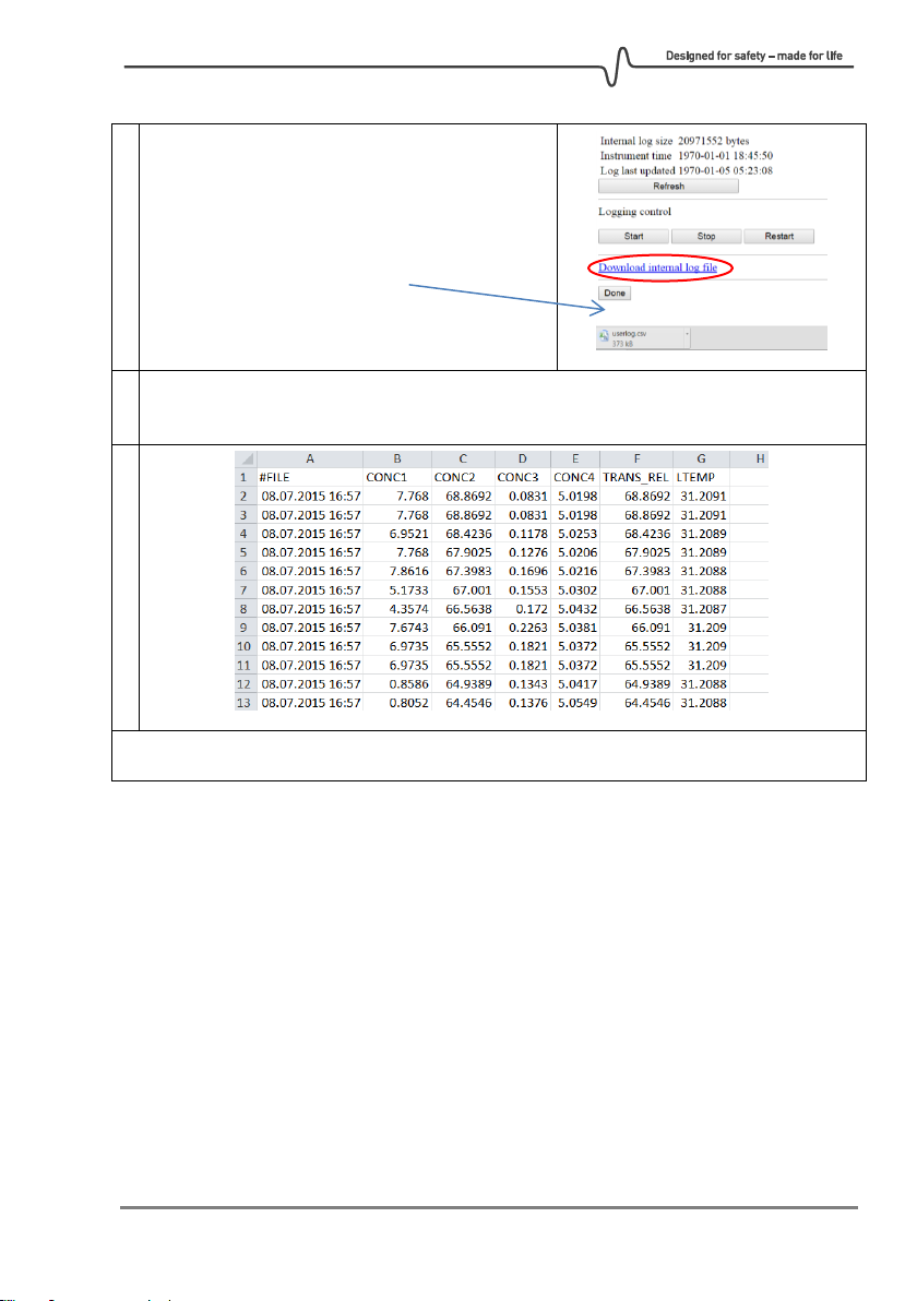
The data log can be downloaded by clicking the
“Download the internal log file”.
Data being downloaded.
7
Data log is exported in CSV format and can then be imported and viewed in a suitable
program as shown below.
Data logging completed.
Page 70

GD1 Page 70 of 76 850-816926-EN R06
THIS PAGE LEFT INTENTIONALLY BLANK
Page 71

GD1 Page 71 of 76 850-816926-EN R06
11. SUPPORT AND CONTACT DETAILS
You will find sales and technical information on our website at
https://gasdetection.3M.com
Email address for general enquiries:
Phone: +33 (0)3 21 60 80 80
11.1. Shipping instruction sending units to support
In case of shipping a GD1 to support please follow the procedure below:
1. Download and save the Diagnostics file as described in section 6.4.
2. Prepare an e-mail with additional important information collected during the
troubleshooting and the following information:
• Unit serial number
• If available, support reference number
• Short description of the error or problem
• A list of all items to be packed in the box
• Contact information with telephone number and e-mail address
3. Attach the Diagnostics file to the e-mail.
4. Send the e-mail to support.
5. Print the e-mail.
6. Turn off the power of the instrument.
7. Dismount the instrument. Do NOT remove the optical housing or the junction box
from the mounting plate.
8. Put the complete GD1 with mounting plate in a protected packing box.
9. Put the printed e-mail in the packing box.
10. Mark the packing box with the following information:
• Unit serial number
• Sender
11. Ship the transmitter unit package to support at:
OLDHAM SAS
R2 Repair Department
ZI Est - Rue Orfila
62027 ARRAS Cédex
FRANCE
Page 72

GD1 Page 72 of 76 850-816926-EN R06
THIS PAGE LEFT INTENTIONALLY BLANK
Page 73

GD1 Page 73 of 76 850-816926-EN R06
THIS PAGE LEFT INTENTIONALLY BLANK
Page 74

GD1 Page 74 of 76 850-816926-EN R06
THIS PAGE LEFT INTENTIONALLY BLANK
Page 75

GD1 Page 75 of 76 850-816926-EN R06
EU DECLARATION OF CONFORMITY
Page 76

EUROPEAN PLANT AND OFFICES
Z.I. Est – rue Orfila CS 20417 – 62027 ARRAS Cedex FRANCE
Tél.: +33 (0)3 21 60 80 80 – Fax: +33 (0)3 21 60 80 00
Web site: https://gasdetection.3M.com
AMERICAS
Tel : +1-713-559-9280
Fax : +1-281-292-2860
ASIA PACIFIC
Tel : +86-21-3127-6373
Fax : +86-21-3127-6365
EUROPE
Tel : +33-321-608-080
Fax : +33-321-608-000
contact info : [email protected]
 Loading...